US4901729A - Ultrasonic probe having ultrasonic propagation medium - Google Patents
Ultrasonic probe having ultrasonic propagation medium Download PDFInfo
- Publication number
- US4901729A US4901729A US07/166,339 US16633988A US4901729A US 4901729 A US4901729 A US 4901729A US 16633988 A US16633988 A US 16633988A US 4901729 A US4901729 A US 4901729A
- Authority
- US
- United States
- Prior art keywords
- ultrasonic
- propagation medium
- rubber
- ultrasonic probe
- cross
- Prior art date
- Legal status (The legal status is an assumption and is not a legal conclusion. Google has not performed a legal analysis and makes no representation as to the accuracy of the status listed.)
- Expired - Lifetime
Links
Images
Classifications
-
- A—HUMAN NECESSITIES
- A61—MEDICAL OR VETERINARY SCIENCE; HYGIENE
- A61B—DIAGNOSIS; SURGERY; IDENTIFICATION
- A61B8/00—Diagnosis using ultrasonic, sonic or infrasonic waves
- A61B8/42—Details of probe positioning or probe attachment to the patient
- A61B8/4272—Details of probe positioning or probe attachment to the patient involving the acoustic interface between the transducer and the tissue
- A61B8/4281—Details of probe positioning or probe attachment to the patient involving the acoustic interface between the transducer and the tissue characterised by sound-transmitting media or devices for coupling the transducer to the tissue
-
- G—PHYSICS
- G10—MUSICAL INSTRUMENTS; ACOUSTICS
- G10K—SOUND-PRODUCING DEVICES; METHODS OR DEVICES FOR PROTECTING AGAINST, OR FOR DAMPING, NOISE OR OTHER ACOUSTIC WAVES IN GENERAL; ACOUSTICS NOT OTHERWISE PROVIDED FOR
- G10K11/00—Methods or devices for transmitting, conducting or directing sound in general; Methods or devices for protecting against, or for damping, noise or other acoustic waves in general
- G10K11/02—Mechanical acoustic impedances; Impedance matching, e.g. by horns; Acoustic resonators
Definitions
- This invention relates to an ultrasonic probe having an ultrasonic propagation medium for use in medical ultrasonic diagnostic systems for examination and inspection within an examining body by transmitting and receiving ultrasonic signals.
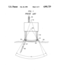
- FIG. 1 is an illustration showing a trapezoidal scanning type of the ultrasonic probe, which can obtain a wide examining region in spite of a small contact area to an examining body.
- numeral 101 denotes an array of transducer elements
- numeral 102 denotes an acoustic matching layer provided along the curved surface of the array 101 of the transducer elements
- numeral 103 denotes an ultrasonic propagation medium arranged in front of the acoustic matching layer 102.
- Numeral 104 denotes lead wires respectively connected to the arrayed transducer elements
- numeral 105 denotes cables which connect the ultrasonic probe to a body of an ultrasonic diagnostic apparatus (not shown)
- numeral 106 denotes an body being examined
- numeral 107 denotes a transmission ultrasonic wave
- numeral 108 denotes a reception ultrasonic wave
- numeral 109 denotes an imagination origin
- numeral 110 denotes a center of curvature of the arrayed transducer elements
- numeral 111 denotes an examining region.
- the acoustic matching layer 102 and the array 101 of the transducer elements arranged in a convexed form are in plane contact with the examining body 106 such as the human body by means of the ultrasonic propagation medium 103 provided in front of the matching layer 102.
- the ultrasonic propagation medium 103 can increase the scanning angle of the ultrasonic waves, namely, enlarge the examined region.
- the ultrasonic waves 107 transmitted, in order, from each of the transducer elements of the array 101 are deflected in the human dbody 106, since an acoustic velocity in the ultrasonic propagation medium 103 is lower than that in the human body 106.
- the deflected ultrasonic waves are reflected within the body 106, and are received by the same transducer element which has emitted the waves.
- the examining region 111 of the ultrasonic signals in the body 106 is of a sector corresponding to a part of a circle whose center is designated at a point 109. This is because the acoustic velocity in the ultrasonic propagation medium 103 is different from that in the human body 106.
- Silicon rubber or the like is used as the above-mentioned ultrasonic propagation medium 103.
- Silicon rubber or the like has an acoustic impedance which is close to an acoustic impedance (about 1.5 to 1.6 ⁇ 10 5 g/cm 2 ⁇ sec) of the humand body 106 and an acoustic velocity (about 1000 m/sec) which is slower than acoustic velocity (about 1540 m/sec) of the human body 106.
- the examining region 111 is enlarged, and the contact surface of the ultrasonic probe with the human body 106 becomes flat. Therefore, there are advantages that the adhesion is good and the operation is easy.
- FIG. 2 is a cross-sectional view showing the other example of the conventional linear scanning type of the ultrasonic probe.
- numeral 201 denotes a case
- numeral 202 denotes an array of transducer elements provided at the front portion of the case 201
- numeral 203 denotes a backing member provided at the rear portion of the array 202 of transducer elements
- numeral 204 denotes lead wires respectively connected to the arrayed transducer elements 202
- numeral 205 denotes a cable connected to a body of an ultrasonic diagnostic apparatus (not shown).
- Numeral 206 denotes a body being examined
- numeral 207 denotes an ultrasonic propagation medium provided between the arrayed transducer elements 202 and the examined body 206.
- the ultrasonic propagation medium 207 comprises a flexible bag 208 made of silicon rubber or the like in which bag degassed water 209 is contained.
- Each of the arrayed transducer elements generates ultrasonic waves in order, with pulse voltage transmitted from the body of the ultrasonic diagnostic apparatus through the cable 205 being applied.
- the resulting ultrasonic waves are emitted to the examined body 206 through the ultrasonic propagation medium 207.
- the ultrasonic waves reflected within the examined body 206 are received by the transducer element which emits the ultrasonic waves, and are changed to electrical signals.
- the electrical signals are sent to the body of the ultrasonic diagnostic apparatus through the cable 205, and are processed so as to display an ultrasonic image.
- the ultrasonic propagation medium 207 By providing the ultrasonic propagation medium 207 between the examined body 206 and the portion for transmitting and receiving the ultrasonic waves, it is possible that the resolving power of the ultrasonic image in the vicinity of the transmitting and receiving portion or the surface of the examined body 206 is improved. Moreover, even if the surface of the examined body 206 has irregularities, the ultrasonic propagation medium 207 can be placed in good contact with the examined body 206. Therefore, there is the advantage that it is easy to obtain the ultrasonic image.
- the ultrasonic attenuation coefficient of the silicon rubber used as the ultrasonic propagation medium 103 is as large as about 1.5 dB/mm at the frequency of 3.5 MHz.
- a sensitivity correcting circuit is indispensable so as to correct the sensitivity difference.
- the ultrasonic propagation medium 207 comprising the rubber-made bag 208 which contains the degassed water 209 is placed in contact with the examined body 206 through a gel (not shown) so as to carry out an ultrasonic diagnosis.
- the silicon-made bag 208 has a high permeability of water
- the degassed water 209 in the bag 208 vaprizes through the silicon rubber-made bag 208 as time proceeds. Therefore, each time the ultrasonic propagation medium 207 is used, the degassed water 209 must be injected in the bag 208.
- the bag 208 containing the degassed water 209 is arranged to be thin, this bag 208 is weak against physical impacts. As a result, there is a problem that the bag 208 is occasionally broken so that the degassed water 209 flows to the examined body 206.
- the present invention has been developed in order to remove the above-mentioned drawbacks inherent to the conventional ultrasonic probe having an ultrasonic propagation medium.
- an object of the present invention to provide an ultrasonic probe having an ultrasonic propagation medium through which an ultrasonic image having a high sensivitiy and a high resolvign power can be obtained.
- Another object of the present invention is to provide an ultrasonic probe having an ultrasonic propagation medium in which the contact of the ultrasonic probe with an examined body and an operability are improved.
- an ultrasonic probe assembly comprising: a body of an ultrasonic probe; and an ultrasonic propagation medium made of rubber containing cross linking agent, the ultrasonic propagation medium being attached to a portion for transmitting and receiving ultrasonic waves of the body of the ultrasonic probe.
- an ultrasonic propagation medium comprising rubber mixed with cross linking agent and cross-linked.
- FIGS. 1 and 2 are an illustration and a cross-sectional view showing the conventional ultrasonic probes respectively;
- FIG. 3 is a cross-secitonal view showing an ultrasonic probe according to one of the embodiments of the present invention.
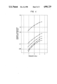
- FIG. 4 is a graphic illustration for describing ultrasonic attenuation coefficients with respect to ultrasonic propagation media according to the present invention and comparative examples.
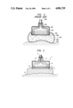
- FIG. 3 is a cross-sectional view of an ultrasonic probe of one embodiment of the present invention.
- numeral 1 denotes a body of an ultrasonic probe
- an array 3 of transducer elements is provided at the lower portion of the body
- the array 3 of the transducer elements has a number of slender plate-like transducer elements linearly successively arranged.
- An acoustic matching layer 4 having a single or multiple layers is provided on the surface of the array 3 of the transducer elements, and an acoustic lens 5 such as silicon rubber for focussing ultrasonic waves is provided on the front surface of the acoustic matching layer 4.
- Each of the transducer elements of the array 3 is connected to a body of an ultrasonic diagnostic apparatus (not shown) through lead wires 6 and a cable 7.
- an ultrasonic propagation medium 8 is interposed between the acousti lens 5 and an examined body or a human body 9.
- the ultrasonic propagation medium 8 is arranged to be larger than the contact area of a portion for transmitting and receiving ultrasonic waves of the body 1 of the ultrasonic probe so that the contact area of the portion is fully covered with the medium 8.
- the thickness of the medium 8 is about 1 to 2 cm for application to a generally flat surface of the examined body 9. In other words, thicker medium 8 may be used for extremely undulatory surfaces of the examined body 9.
- the acoustic matching layer 4 and the acoustic lens 5 are conventionally used because the acoustic matching layer 4 can transmit ultrasonic waves efficiently and the acoustic lens 5 can focus ultrasonic waves to improve a resolving power, but are not shown in FIG. 2 for simplicity.
- the ultrasonic probe having the ultrasonic propagation medium 8 satisfactorily operates irrespective of the presence of the acoustic matching layer 4 and the acoustic lens 5.
- This ultrasonic propagation medium 8 is made of rubber such as butadiene rubber which is cross linked by added peroxide. An acoustic impedance of such ultrasonic propagation medium 8 is close to that of the examined body 9, and an ultrsonic attenuation coefficient of the medium 8 is extremely small.
- Each of the arrayed transducer elements generates ultrasonic waves in order, with pulse voltage transmitted from the body of the ultrasonic diagnostic apparatus through the cable 7 being applied.
- the resulting ultrasonic waves are emitted to the examined body 9 through the acoustic matching layer 4, the acoustic lens 5, and the ultrasonic propagation medium 8.
- the ultrasonic waves reflected within the examined body 9 are received by the same transducer element which emits the ultrasonic waves, and are converted into electrical signals.
- the electrical signals are sent to the body of the ultrasonic diagnostic apparatus through the cable 7, and are processed so as to display an ultrasonic image.
- This dicumyl peroxide cross-linked agent is a mixture of 40 parts of dicumyl peroxide used as a main component and 60 parts of calcium carbonate by weight, and is known as KAYAKUMIRU.D-40C produced by Kayaku-Nuri Co., Ltd. one hundred parts of butadiene rubber are mixed by 1.7 parts of dicumyl peroxide cross-linking agent (i.e. 0.68 parts of pure dicumyl peroxide) by weight, and the mixture is cross-linked under conditions of a temperature of about 170° C.
- the acoustic impedance (about 1.44 ⁇ 10 5 g/cm 2 ⁇ sec) of the resulting ultrasonic propagation medium 8 is close to that of the examined body 9.
- the acoustic velocity (1570 m/sec) in the ultrasonic propagation medium 8 is also close to that in the examined body 9.
- the ultrasonic attenuation coefficient is 0.18 dB/mm. This value is about 1/10 of that of silicon rubber which is 1.5 dB/mm.
- FIG. 4 is a graph showing the variation of the ultrasonic attenuation coefficient when varying the amount of dicumyl peroxide cross linking agent which is added to butadiene rubber.
- curves from A to C are obtained by mixtures and treatment thereof as follows.
- the mixtures are cross-linked under conditions of a temperature of about 170° C. and a time of about 15 min.
- ultrasonic attenuation coefficients decrease as the amounts of dicumyl peroxide cross linking agent is reduced.
- curve A where 0.2 parts of dicumyl peroxide cross-linking agent is added, the acoustic attenuation coefficient is 0.12 dB/mm at a frequency of 3.5 MHz, and the acoustic impedance (1.44 ⁇ 10 5 g/cm 2 ⁇ sec) is equal to that shown by curve C.
- the ultrasonic attenuation coefficient of the conventional silicon rubber, and the ultrasonic attenuation coefficient of vulcanized butadiene rubber in which 1.5 parts of sulfur are added to 100 parts of butadiene rubber by weight are respectively shown by curves E and D in FIG. 4.
- Silicon rubber shown by curve E has a large ultrasonic attenuation coefficient, and moreover, the ultrasonic attenuation coefficient of the sulfur-vulcanized butadiene rubber shown by curve D is about 0.3 dB/mm at 3.5 MHz so that the value is larger than those of butadiene rubbers cross-linked by dicumyl peroxide cross-linking agent.
- the ultrasonic attenuation coefficient of butadiene rubber has a tendency to increase in accordance with the increment of the amount of dicumyl peroxide cross-linking agent.
- the ultrasonic attenuation coefficient is 0.35 dB/mm at 3.5 MHz which value is larger than that of sulfur-vulcanized butadiene rubber (shown by D in FIG. 4).
- the cross-linked butadiene rubber has a low ultrasonic attenuation coefficient, and can be used practically, when to 100 parts of rubber, the amount of dicumyl peroxide cross linking-agent is set less than 2 parts (i.e. 0.8 parts of pure dicumyl peroxide).
- the acoustic impedance of the above-mentioned ultrasonic propagation medium 8 is close to that of the examined body 9, there is no mismatching in the vicinity of the examined body 9, thereby preventing the deterioration of the resolving power of images due to multiple reflection.
- the ultrasonic attenuation coefficient is about 1/10 of that of the conventional silicon rubber. Therefore, when the ultrasonic propagation medium 8 of the present invention is used in the trapezoidal scanning type of the ultrasonic probe shown in FIG. 1, the sensitivity variation throughout the entire examining region becomes extremely small.
- this sensitivity variation is caused by the difference of the thickness between the center portion where the ultrasaonic propagation medium 103 is thin and both end portions where the ultrasonic propagation medium 103 is thick. As a result, it is unnecessary to provide a sensitivity correcting circuit.
- Butadiene-styrene rubber is used as a main component of the ultrasonic propagation medium 8 of the above-mentioned embodiment.
- natural rubber, isoprene rubber, butadiene-styrene rubber, ethylene-propylene rubber, and the like can also be used.
- benzoyl peroxide, 1,4 (or 1,3)-bis (t-butylperoxy isopropyl) benzene, 2,5-dimethyl-2,5-di (t-butylperoxy) hexane, 1,1-bis-t-butylperoxy-3,3,5-trimethyl cylcohexane, n-butyl-4,4-bis (t-butylperoxy) valerate, t-butylperoxy isopropylcarbonate, and the like can be also used.
- butadiene rubber is mixed by dicumyl peroxide cross-linking agent, and the resulting mixture is cross-linked.
- carbon black, zinc oxide, titanium oxide, silicic anhydride, calcium silicate, colloidal gravum carbonate, or the like can be also added to the mixture of butadiene rubber and dicumyl peroxide cross-linking agent so as to bring the acoustic impedance of the ultrasonic propagation medium 8 close to the acoustic impedance of the examined body 9.
- the acoustic impedance of the ultrasonic propagation medium 8 becomes 1.65 ⁇ 10 5 g/cm 2 ⁇ sec which value is substantially equal to the acoustic impedance (1.5 to 1.6 ⁇ 10 5 g/cm 2 ⁇ sec) of the examined body 9.
- the ultrasonic attenuation coefficient 0.3 to 0.4 dB/mm at MHz
- this value is about 1/5 of that of the conventional silicon rubber so that the resulting ultrasonic propagation medium 8 can be used practically.
- the above-mentioned additives can be also used practically.
- the acoustic impedance is close to the impedance (1.5 to 1.6 ⁇ 10 5 g/cm 2 ⁇ sec) of the examined body 9.
- This medium 8 has a low hardness, and an easiness for handling so as to be placed in good contact with the examined body 9.
- This medium 8 has chemical stability.
- the ultrasonic propagation medium 8 of this invention satisfies the properties of (1) and (2) as is apparent from the detailed description of the above.
- the desirable hardness of the medium 8 can be freely obtained by chanign the amount of the cross-linking agent.
- the hardness (shore hardness A) is about 50.
- the hardness (shore hardness A) becomes about 30.
- a gel-like medium 8 can be also obtained as well, by decreasing the amount of dicumyl peroxide cross-linking agent.
- the ultrasonic propagation medium 8 having a low hardness can be obtained freely so that the medium 8 is in good contact with the examined body 9.
- This medium 8 has a chemical stability so that this medium 8 is stable to water or alcohol which is used very frequently and has no bad effects on the examined body 9.
- the ultrasonic propagation medium 8 comprising the cross-linked rubber is interposed between the examined body 9 and the surface of the portion for transmitting and receiving the ultrasonic waves. Therefore, it is unnecessary to inject degassed water into the rubber-made bag each time the bag is used as in the prior art. Moreover, there is no problem of wetting the examined body 9 with the bag being broken by physical impact. Besides, since the acoustic impedance of the medium 8 is close to that of the examined body 9, there is no multiple reflection in the vicinity of the boundary between the medium 8 and the examined body 9. And, since the ultrasonic attenuation coefficient is extremely small, the decrease of the sensitivity due to the use of the medium 8 is small. Moreover, since the ultrasonic propagation medium 8 is soft, the ultrasonic probe can be obtained which is palced in good contact with the examined body 9, has no deterioration of the properties, and has good operability.
- the linear type of the ultrasonic probe and the convex type of the ultrasonic probe have been described.
- the ultrasonic propagation medium 8 can be applied to the duplex type or the like of the ultrasonic probe as well.
- the ultrasonic propagation medium 8 can be fixed to the surface of the portion for transmitting and receiving the ultrasonic waves of the body 1 of the ultrasonic probe by adhesions or the like, and can be detachably disposed to the bodies of the various types of the ultrasonic probes.
Abstract
Description
______________________________________
Composition of Mixtures
parts of dicumyl
peroxide cross linking
                   parts of pure dicumyl
agent by weight    peroxide by weight
(to 100 parts of   (to 100 parts of butadiene
butadiene rubber)  rubber)
______________________________________
A     0.2              0.08
B      0.85            0.34
C     1.7              0.68
______________________________________
Claims (5)
Applications Claiming Priority (2)
| Application Number | Priority Date | Filing Date | Title |
|---|---|---|---|
| JP62-54555 | 1987-03-10 | ||
| JP62054555A JPS63220847A (en) | 1987-03-10 | 1987-03-10 | Ultrasonic probe |
Publications (1)
| Publication Number | Publication Date |
|---|---|
| US4901729A true US4901729A (en) | 1990-02-20 |
Family
ID=12973928
Family Applications (1)
| Application Number | Title | Priority Date | Filing Date |
|---|---|---|---|
| US07/166,339 Expired - Lifetime US4901729A (en) | 1987-03-10 | 1988-03-10 | Ultrasonic probe having ultrasonic propagation medium |
Country Status (4)
| Country | Link |
|---|---|
| US (1) | US4901729A (en) |
| EP (1) | EP0283854B1 (en) |
| JP (1) | JPS63220847A (en) |
| DE (1) | DE3881419T2 (en) |
Cited By (69)
| Publication number | Priority date | Publication date | Assignee | Title |
|---|---|---|---|---|
| US5050128A (en) * | 1986-04-02 | 1991-09-17 | Matsushita Electric Industrial Co., Ltd. | Ultrasonic probe having an ultrasonic propagation medium |
| US5127410A (en) * | 1990-12-06 | 1992-07-07 | Hewlett-Packard Company | Ultrasound probe and lens assembly for use therein |
| US5265614A (en) * | 1988-08-30 | 1993-11-30 | Fujitsu Limited | Acoustic coupler |
| US5280722A (en) * | 1991-08-29 | 1994-01-25 | Madaras Eric I | Method and apparatus for indicating disbonds in joint regions |
| WO1994004073A1 (en) * | 1992-08-25 | 1994-03-03 | Zertl Medical Inc. | Blood flow monitoring system |
| US5318035A (en) * | 1991-12-02 | 1994-06-07 | Nitto Denko Corporation | Crosslinked molding, sound medium using it and ultrasonic coupler |
| US5333612A (en) * | 1993-08-26 | 1994-08-02 | Wild John J | Volumetric breast interogation device |
| US5465724A (en) * | 1993-05-28 | 1995-11-14 | Acuson Corporation | Compact rotationally steerable ultrasound transducer |
| US5575291A (en) * | 1993-11-17 | 1996-11-19 | Fujitsu Ltd. | Ultrasonic coupler |
| US5685307A (en) * | 1995-02-28 | 1997-11-11 | Iowa State University Research Foundation, Inc. | Method and apparatus for tissue characterization of animals using ultrasound |
| US5913825A (en) * | 1996-07-19 | 1999-06-22 | Kanda Tsushin Kogyo Co., Ltd. | Ultrasonic probe and ultrasonic survey instrument |
| US6418084B2 (en) * | 2000-07-13 | 2002-07-09 | Matsushita Electric Industrial Co., Ltd. | Ultrasonic probe and method of manufacturing the same |
| US6623430B1 (en) | 1997-10-14 | 2003-09-23 | Guided Therapy Systems, Inc. | Method and apparatus for safety delivering medicants to a region of tissue using imaging, therapy and temperature monitoring ultrasonic system |
| US20040220458A1 (en) * | 2003-05-02 | 2004-11-04 | Burd John F. | Method and instruments for non-invasive analyte measurement |
| US20050070801A1 (en) * | 2003-09-29 | 2005-03-31 | Yohachi Yamashita | Acoustic lens composition, ultrasonic probe, and ultrasonic diagnostic apparatus |
| US20050085701A1 (en) * | 2003-10-21 | 2005-04-21 | Burd John F. | Methods for non-invasive analyte measurement from the conjunctiva |
| US20060173304A1 (en) * | 2002-11-27 | 2006-08-03 | Shih-Ping Wang | Volumetric ultrasound scanning of smaller-sized breast |
| US20060224057A1 (en) * | 2003-10-21 | 2006-10-05 | Oculir, Inc. | Methods for non-invasive analyte measurement |
| US20060258919A1 (en) * | 2004-04-14 | 2006-11-16 | Oculir, Inc. | Non-Invasive Analyte Measurement Device for Measuring Tears and Other Ocular Elements Using Electromagnetic Radiation and Method of Using the Same |
| US20080009688A1 (en) * | 2004-04-14 | 2008-01-10 | Oculir, Inc. | Methods for non-invasive analyte measurement |
| US20080243004A1 (en) * | 2007-03-30 | 2008-10-02 | Fujifilm Corporation | Ultrasonic probe, method of manufacturing the same, and ultrasonic diagnostic apparatus |
| US20080294073A1 (en) * | 2006-09-18 | 2008-11-27 | Guided Therapy Systems, Inc. | Method and sysem for non-ablative acne treatment and prevention |
| US20090062655A1 (en) * | 2006-01-31 | 2009-03-05 | Matsushita Electric Industrial Co., Ltd. | Ultrasonic probe |
| US20090093708A1 (en) * | 2005-07-29 | 2009-04-09 | Long Wang | MRI guided high-intensity focused ultrasonic therapeutic system |
| US20090216159A1 (en) * | 2004-09-24 | 2009-08-27 | Slayton Michael H | Method and system for combined ultrasound treatment |
| US20100022922A1 (en) * | 2004-10-06 | 2010-01-28 | Guided Therapy Systems, L.L.C. | Method and system for treating stretch marks |
| US20100160782A1 (en) * | 2004-10-06 | 2010-06-24 | Guided Therapy Systems, Llc | Methods and systems for fat reduction and/or cellulite treatment |
| US20110112405A1 (en) * | 2008-06-06 | 2011-05-12 | Ulthera, Inc. | Hand Wand for Ultrasonic Cosmetic Treatment and Imaging |
| US8636665B2 (en) | 2004-10-06 | 2014-01-28 | Guided Therapy Systems, Llc | Method and system for ultrasound treatment of fat |
| US8641622B2 (en) | 2004-10-06 | 2014-02-04 | Guided Therapy Systems, Llc | Method and system for treating photoaged tissue |
| US8690779B2 (en) | 2004-10-06 | 2014-04-08 | Guided Therapy Systems, Llc | Noninvasive aesthetic treatment for tightening tissue |
| US8857438B2 (en) | 2010-11-08 | 2014-10-14 | Ulthera, Inc. | Devices and methods for acoustic shielding |
| US8858471B2 (en) | 2011-07-10 | 2014-10-14 | Guided Therapy Systems, Llc | Methods and systems for ultrasound treatment |
| US8868958B2 (en) | 2005-04-25 | 2014-10-21 | Ardent Sound, Inc | Method and system for enhancing computer peripheral safety |
| US8915853B2 (en) | 2004-10-06 | 2014-12-23 | Guided Therapy Systems, Llc | Methods for face and neck lifts |
| US20150000408A1 (en) * | 2012-03-20 | 2015-01-01 | Alstom Technology Ltd | Ultrasonic ndt sensor arrangement and method for inspecting surfaces of variable geometry of metal bodies |
| US8932224B2 (en) | 2004-10-06 | 2015-01-13 | Guided Therapy Systems, Llc | Energy based hyperhidrosis treatment |
| US9011337B2 (en) | 2011-07-11 | 2015-04-21 | Guided Therapy Systems, Llc | Systems and methods for monitoring and controlling ultrasound power output and stability |
| US9011336B2 (en) | 2004-09-16 | 2015-04-21 | Guided Therapy Systems, Llc | Method and system for combined energy therapy profile |
| US9039617B2 (en) | 2009-11-24 | 2015-05-26 | Guided Therapy Systems, Llc | Methods and systems for generating thermal bubbles for improved ultrasound imaging and therapy |
| US9114247B2 (en) | 2004-09-16 | 2015-08-25 | Guided Therapy Systems, Llc | Method and system for ultrasound treatment with a multi-directional transducer |
| US9149658B2 (en) | 2010-08-02 | 2015-10-06 | Guided Therapy Systems, Llc | Systems and methods for ultrasound treatment |
| US20150343191A1 (en) * | 2012-12-28 | 2015-12-03 | Bard Peripheral Vascular | Drug delivery via mechanical vibration balloon |
| US9216276B2 (en) | 2007-05-07 | 2015-12-22 | Guided Therapy Systems, Llc | Methods and systems for modulating medicants using acoustic energy |
| US9263663B2 (en) | 2012-04-13 | 2016-02-16 | Ardent Sound, Inc. | Method of making thick film transducer arrays |
| US9272162B2 (en) | 1997-10-14 | 2016-03-01 | Guided Therapy Systems, Llc | Imaging, therapy, and temperature monitoring ultrasonic method |
| US9320537B2 (en) | 2004-10-06 | 2016-04-26 | Guided Therapy Systems, Llc | Methods for noninvasive skin tightening |
| US9504446B2 (en) | 2010-08-02 | 2016-11-29 | Guided Therapy Systems, Llc | Systems and methods for coupling an ultrasound source to tissue |
| US9510802B2 (en) | 2012-09-21 | 2016-12-06 | Guided Therapy Systems, Llc | Reflective ultrasound technology for dermatological treatments |
| US9694212B2 (en) | 2004-10-06 | 2017-07-04 | Guided Therapy Systems, Llc | Method and system for ultrasound treatment of skin |
| US9700340B2 (en) | 2004-10-06 | 2017-07-11 | Guided Therapy Systems, Llc | System and method for ultra-high frequency ultrasound treatment |
| US9827449B2 (en) | 2004-10-06 | 2017-11-28 | Guided Therapy Systems, L.L.C. | Systems for treating skin laxity |
| US9907535B2 (en) | 2000-12-28 | 2018-03-06 | Ardent Sound, Inc. | Visual imaging system for ultrasonic probe |
| US10039938B2 (en) | 2004-09-16 | 2018-08-07 | Guided Therapy Systems, Llc | System and method for variable depth ultrasound treatment |
| US10420960B2 (en) | 2013-03-08 | 2019-09-24 | Ulthera, Inc. | Devices and methods for multi-focus ultrasound therapy |
| US10561862B2 (en) | 2013-03-15 | 2020-02-18 | Guided Therapy Systems, Llc | Ultrasound treatment device and methods of use |
| US10603521B2 (en) | 2014-04-18 | 2020-03-31 | Ulthera, Inc. | Band transducer ultrasound therapy |
| US10864385B2 (en) | 2004-09-24 | 2020-12-15 | Guided Therapy Systems, Llc | Rejuvenating skin by heating tissue for cosmetic treatment of the face and body |
| US11072707B2 (en) | 2016-09-27 | 2021-07-27 | Fujifilm Corporation | Resin material for acoustic wave probe, acoustic lens, acoustic wave probe, acoustic wave measurement apparatus, ultrasonic diagnostic apparatus, photoacoustic wave measurement apparatus, and ultrasound endoscope |
| US11207548B2 (en) | 2004-10-07 | 2021-12-28 | Guided Therapy Systems, L.L.C. | Ultrasound probe for treating skin laxity |
| US11213274B2 (en) * | 2015-11-09 | 2022-01-04 | Cal Tenn Innovation, Inc. | Ultrashield devices and methods for use in ultrasonic procedures |
| US11224895B2 (en) | 2016-01-18 | 2022-01-18 | Ulthera, Inc. | Compact ultrasound device having annular ultrasound array peripherally electrically connected to flexible printed circuit board and method of assembly thereof |
| US11235179B2 (en) | 2004-10-06 | 2022-02-01 | Guided Therapy Systems, Llc | Energy based skin gland treatment |
| US11241218B2 (en) | 2016-08-16 | 2022-02-08 | Ulthera, Inc. | Systems and methods for cosmetic ultrasound treatment of skin |
| US11524099B2 (en) | 2015-06-30 | 2022-12-13 | Fujifilm Corporation | Composition for acoustic wave probe, silicone resin for acoustic wave probe using the same, acoustic wave probe, ultrasound probe, acoustic wave measurement apparatus, ultrasound diagnostic apparatus, photoacoustic wave measurement apparatus, and ultrasound endoscope |
| US11717661B2 (en) | 2007-05-07 | 2023-08-08 | Guided Therapy Systems, Llc | Methods and systems for ultrasound assisted delivery of a medicant to tissue |
| US11724133B2 (en) | 2004-10-07 | 2023-08-15 | Guided Therapy Systems, Llc | Ultrasound probe for treatment of skin |
| US11883688B2 (en) | 2004-10-06 | 2024-01-30 | Guided Therapy Systems, Llc | Energy based fat reduction |
| US11944849B2 (en) | 2018-02-20 | 2024-04-02 | Ulthera, Inc. | Systems and methods for combined cosmetic treatment of cellulite with ultrasound |
Families Citing this family (12)
| Publication number | Priority date | Publication date | Assignee | Title |
|---|---|---|---|---|
| DE69021158T2 (en) * | 1989-09-29 | 1995-12-07 | Terumo Corp | Ultrasonic coupler and manufacturing process. |
| ATE120949T1 (en) * | 1990-02-02 | 1995-04-15 | Krauth Peter Gmbh | DEVICE FOR WET TREATMENT WITH ULTRASOUND. |
| EP0800788A1 (en) * | 1996-04-10 | 1997-10-15 | Lec Tec Corporation | Solid ultrasonic biomedical couplant sheet |
| GB9610511D0 (en) * | 1996-05-20 | 1996-07-31 | Cantwell Evelyna D | Scanning ultrasound probe |
| US5782767A (en) * | 1996-12-31 | 1998-07-21 | Diagnostic Ultrasound Corporation | Coupling pad for use with medical ultrasound devices |
| JP2000005180A (en) * | 1998-06-25 | 2000-01-11 | Olympus Optical Co Ltd | Acoustic impedance measuring device |
| US6843771B2 (en) | 2003-01-15 | 2005-01-18 | Salutron, Inc. | Ultrasonic monitor for measuring heart rate and blood flow rate |
| CN1982375A (en) * | 2003-09-29 | 2007-06-20 | 株式会社东芝 | Acoustic lens composition, and ultrasonic probe and ultrasonic diagnostic apparatus |
| GB0508250D0 (en) * | 2005-04-23 | 2005-06-01 | Smith & Nephew | Composition |
| JP5179836B2 (en) * | 2007-11-02 | 2013-04-10 | 富士フイルム株式会社 | Ultrasonic probe |
| JP2019187868A (en) * | 2018-04-26 | 2019-10-31 | コニカミノルタ株式会社 | Ultrasonic probe and ultrasonic diagnostic apparatus |
| CN117795383A (en) * | 2021-07-16 | 2024-03-29 | 道达尔能源一技术公司 | Sensor device for geophysical measurements intended to be placed on the surface of the earth, related assembly and method for deploying and retrieving such a sensor |
Citations (10)
| Publication number | Priority date | Publication date | Assignee | Title |
|---|---|---|---|---|
| GB2009563A (en) * | 1977-11-24 | 1979-06-13 | Emi Ltd | Ultrasonic probes |
| GB1558718A (en) * | 1976-04-28 | 1980-01-09 | Tokyo Shibaura Electric Co | Probe for ultrasonic diagnostic apparatus |
| EP0043158A1 (en) * | 1980-07-02 | 1982-01-06 | Philips Patentverwaltung GmbH | Ultrasonic investigation apparatus |
| JPS587231A (en) * | 1981-07-07 | 1983-01-17 | 松下電器産業株式会社 | Ultrasonic diagnostic apparatus |
| US4440025A (en) * | 1980-06-27 | 1984-04-03 | Matsushita Electric Industrial Company, Limited | Arc scan transducer array having a diverging lens |
| EP0210723A1 (en) * | 1985-05-20 | 1987-02-04 | Matsushita Electric Industrial Co., Ltd. | Ultrasonic probe |
| EP0239999A2 (en) * | 1986-04-02 | 1987-10-07 | Matsushita Electric Industrial Co., Ltd. | Ultrasonic probe having an ultrasonic propagation medium |
| US4699150A (en) * | 1983-06-07 | 1987-10-13 | Matsushita Electric Industrial Co., Ltd. | Ultrasonic transducer assembly for medical diagnostic examinations |
| US4760738A (en) * | 1986-07-08 | 1988-08-02 | Kabushiki Kaisha Komatsu Seisakusho | Contact medium for use in probe of ultrasonic flaw detector |
| US4769571A (en) * | 1987-08-28 | 1988-09-06 | The Institue Of Paper Chemistry | Ultrasonic transducer |
-
1987
- 1987-03-10 JP JP62054555A patent/JPS63220847A/en active Pending
-
1988
- 1988-03-09 DE DE88103726T patent/DE3881419T2/en not_active Expired - Lifetime
- 1988-03-09 EP EP88103726A patent/EP0283854B1/en not_active Expired - Lifetime
- 1988-03-10 US US07/166,339 patent/US4901729A/en not_active Expired - Lifetime
Patent Citations (10)
| Publication number | Priority date | Publication date | Assignee | Title |
|---|---|---|---|---|
| GB1558718A (en) * | 1976-04-28 | 1980-01-09 | Tokyo Shibaura Electric Co | Probe for ultrasonic diagnostic apparatus |
| GB2009563A (en) * | 1977-11-24 | 1979-06-13 | Emi Ltd | Ultrasonic probes |
| US4440025A (en) * | 1980-06-27 | 1984-04-03 | Matsushita Electric Industrial Company, Limited | Arc scan transducer array having a diverging lens |
| EP0043158A1 (en) * | 1980-07-02 | 1982-01-06 | Philips Patentverwaltung GmbH | Ultrasonic investigation apparatus |
| JPS587231A (en) * | 1981-07-07 | 1983-01-17 | 松下電器産業株式会社 | Ultrasonic diagnostic apparatus |
| US4699150A (en) * | 1983-06-07 | 1987-10-13 | Matsushita Electric Industrial Co., Ltd. | Ultrasonic transducer assembly for medical diagnostic examinations |
| EP0210723A1 (en) * | 1985-05-20 | 1987-02-04 | Matsushita Electric Industrial Co., Ltd. | Ultrasonic probe |
| EP0239999A2 (en) * | 1986-04-02 | 1987-10-07 | Matsushita Electric Industrial Co., Ltd. | Ultrasonic probe having an ultrasonic propagation medium |
| US4760738A (en) * | 1986-07-08 | 1988-08-02 | Kabushiki Kaisha Komatsu Seisakusho | Contact medium for use in probe of ultrasonic flaw detector |
| US4769571A (en) * | 1987-08-28 | 1988-09-06 | The Institue Of Paper Chemistry | Ultrasonic transducer |
Non-Patent Citations (1)
| Title |
|---|
| A study of ultrasonographic examination of thyroid disease by a simple small water bag made of silicone gum by H. Katano et al; JSUM Proceedings, 1985, pp. 347 and 348. * |
Cited By (145)
| Publication number | Priority date | Publication date | Assignee | Title |
|---|---|---|---|---|
| US5050128A (en) * | 1986-04-02 | 1991-09-17 | Matsushita Electric Industrial Co., Ltd. | Ultrasonic probe having an ultrasonic propagation medium |
| US5265614A (en) * | 1988-08-30 | 1993-11-30 | Fujitsu Limited | Acoustic coupler |
| US5127410A (en) * | 1990-12-06 | 1992-07-07 | Hewlett-Packard Company | Ultrasound probe and lens assembly for use therein |
| US5280722A (en) * | 1991-08-29 | 1994-01-25 | Madaras Eric I | Method and apparatus for indicating disbonds in joint regions |
| US5318035A (en) * | 1991-12-02 | 1994-06-07 | Nitto Denko Corporation | Crosslinked molding, sound medium using it and ultrasonic coupler |
| WO1994004073A1 (en) * | 1992-08-25 | 1994-03-03 | Zertl Medical Inc. | Blood flow monitoring system |
| US5465724A (en) * | 1993-05-28 | 1995-11-14 | Acuson Corporation | Compact rotationally steerable ultrasound transducer |
| US5333612A (en) * | 1993-08-26 | 1994-08-02 | Wild John J | Volumetric breast interogation device |
| US5575291A (en) * | 1993-11-17 | 1996-11-19 | Fujitsu Ltd. | Ultrasonic coupler |
| US5685307A (en) * | 1995-02-28 | 1997-11-11 | Iowa State University Research Foundation, Inc. | Method and apparatus for tissue characterization of animals using ultrasound |
| US5913825A (en) * | 1996-07-19 | 1999-06-22 | Kanda Tsushin Kogyo Co., Ltd. | Ultrasonic probe and ultrasonic survey instrument |
| US6623430B1 (en) | 1997-10-14 | 2003-09-23 | Guided Therapy Systems, Inc. | Method and apparatus for safety delivering medicants to a region of tissue using imaging, therapy and temperature monitoring ultrasonic system |
| US9272162B2 (en) | 1997-10-14 | 2016-03-01 | Guided Therapy Systems, Llc | Imaging, therapy, and temperature monitoring ultrasonic method |
| US6418084B2 (en) * | 2000-07-13 | 2002-07-09 | Matsushita Electric Industrial Co., Ltd. | Ultrasonic probe and method of manufacturing the same |
| US9907535B2 (en) | 2000-12-28 | 2018-03-06 | Ardent Sound, Inc. | Visual imaging system for ultrasonic probe |
| US20060173304A1 (en) * | 2002-11-27 | 2006-08-03 | Shih-Ping Wang | Volumetric ultrasound scanning of smaller-sized breast |
| US6958039B2 (en) | 2003-05-02 | 2005-10-25 | Oculir, Inc. | Method and instruments for non-invasive analyte measurement |
| US20040220458A1 (en) * | 2003-05-02 | 2004-11-04 | Burd John F. | Method and instruments for non-invasive analyte measurement |
| US20050070801A1 (en) * | 2003-09-29 | 2005-03-31 | Yohachi Yamashita | Acoustic lens composition, ultrasonic probe, and ultrasonic diagnostic apparatus |
| US8292818B2 (en) | 2003-09-29 | 2012-10-23 | Kabushiki Kaisha Toshiba | Acoustic lens composition, ultrasonic probe, and ultrasonic diagnostic apparatus |
| US20090069486A1 (en) * | 2003-09-29 | 2009-03-12 | Yohachi Yamashita | Acoustic lens composition, ultrasonic probe, and ultrasonic diagnostic apparatus |
| US20060224057A1 (en) * | 2003-10-21 | 2006-10-05 | Oculir, Inc. | Methods for non-invasive analyte measurement |
| US20050085701A1 (en) * | 2003-10-21 | 2005-04-21 | Burd John F. | Methods for non-invasive analyte measurement from the conjunctiva |
| US20060258919A1 (en) * | 2004-04-14 | 2006-11-16 | Oculir, Inc. | Non-Invasive Analyte Measurement Device for Measuring Tears and Other Ocular Elements Using Electromagnetic Radiation and Method of Using the Same |
| US20080009688A1 (en) * | 2004-04-14 | 2008-01-10 | Oculir, Inc. | Methods for non-invasive analyte measurement |
| US10039938B2 (en) | 2004-09-16 | 2018-08-07 | Guided Therapy Systems, Llc | System and method for variable depth ultrasound treatment |
| US9011336B2 (en) | 2004-09-16 | 2015-04-21 | Guided Therapy Systems, Llc | Method and system for combined energy therapy profile |
| US9114247B2 (en) | 2004-09-16 | 2015-08-25 | Guided Therapy Systems, Llc | Method and system for ultrasound treatment with a multi-directional transducer |
| US20090216159A1 (en) * | 2004-09-24 | 2009-08-27 | Slayton Michael H | Method and system for combined ultrasound treatment |
| US9895560B2 (en) | 2004-09-24 | 2018-02-20 | Guided Therapy Systems, Llc | Methods for rejuvenating skin by heating tissue for cosmetic treatment of the face and body |
| US10328289B2 (en) | 2004-09-24 | 2019-06-25 | Guided Therapy Systems, Llc | Rejuvenating skin by heating tissue for cosmetic treatment of the face and body |
| US10864385B2 (en) | 2004-09-24 | 2020-12-15 | Guided Therapy Systems, Llc | Rejuvenating skin by heating tissue for cosmetic treatment of the face and body |
| US9095697B2 (en) | 2004-09-24 | 2015-08-04 | Guided Therapy Systems, Llc | Methods for preheating tissue for cosmetic treatment of the face and body |
| US11590370B2 (en) | 2004-09-24 | 2023-02-28 | Guided Therapy Systems, Llc | Rejuvenating skin by heating tissue for cosmetic treatment of the face and body |
| US20100160782A1 (en) * | 2004-10-06 | 2010-06-24 | Guided Therapy Systems, Llc | Methods and systems for fat reduction and/or cellulite treatment |
| US9522290B2 (en) | 2004-10-06 | 2016-12-20 | Guided Therapy Systems, Llc | System and method for fat and cellulite reduction |
| US8672848B2 (en) | 2004-10-06 | 2014-03-18 | Guided Therapy Systems, Llc | Method and system for treating cellulite |
| US8690779B2 (en) | 2004-10-06 | 2014-04-08 | Guided Therapy Systems, Llc | Noninvasive aesthetic treatment for tightening tissue |
| US8690778B2 (en) | 2004-10-06 | 2014-04-08 | Guided Therapy Systems, Llc | Energy-based tissue tightening |
| US8690780B2 (en) | 2004-10-06 | 2014-04-08 | Guided Therapy Systems, Llc | Noninvasive tissue tightening for cosmetic effects |
| US10603523B2 (en) | 2004-10-06 | 2020-03-31 | Guided Therapy Systems, Llc | Ultrasound probe for tissue treatment |
| US10610705B2 (en) | 2004-10-06 | 2020-04-07 | Guided Therapy Systems, L.L.C. | Ultrasound probe for treating skin laxity |
| US10603519B2 (en) | 2004-10-06 | 2020-03-31 | Guided Therapy Systems, Llc | Energy based fat reduction |
| US10532230B2 (en) | 2004-10-06 | 2020-01-14 | Guided Therapy Systems, Llc | Methods for face and neck lifts |
| US8915853B2 (en) | 2004-10-06 | 2014-12-23 | Guided Therapy Systems, Llc | Methods for face and neck lifts |
| US8915870B2 (en) | 2004-10-06 | 2014-12-23 | Guided Therapy Systems, Llc | Method and system for treating stretch marks |
| US8915854B2 (en) | 2004-10-06 | 2014-12-23 | Guided Therapy Systems, Llc | Method for fat and cellulite reduction |
| US8920324B2 (en) | 2004-10-06 | 2014-12-30 | Guided Therapy Systems, Llc | Energy based fat reduction |
| US11717707B2 (en) | 2004-10-06 | 2023-08-08 | Guided Therapy Systems, Llc | System and method for noninvasive skin tightening |
| US8932224B2 (en) | 2004-10-06 | 2015-01-13 | Guided Therapy Systems, Llc | Energy based hyperhidrosis treatment |
| US10525288B2 (en) | 2004-10-06 | 2020-01-07 | Guided Therapy Systems, Llc | System and method for noninvasive skin tightening |
| US11697033B2 (en) | 2004-10-06 | 2023-07-11 | Guided Therapy Systems, Llc | Methods for lifting skin tissue |
| US8641622B2 (en) | 2004-10-06 | 2014-02-04 | Guided Therapy Systems, Llc | Method and system for treating photoaged tissue |
| US9039619B2 (en) | 2004-10-06 | 2015-05-26 | Guided Therapy Systems, L.L.C. | Methods for treating skin laxity |
| US8636665B2 (en) | 2004-10-06 | 2014-01-28 | Guided Therapy Systems, Llc | Method and system for ultrasound treatment of fat |
| US10888718B2 (en) | 2004-10-06 | 2021-01-12 | Guided Therapy Systems, L.L.C. | Ultrasound probe for treating skin laxity |
| US10265550B2 (en) | 2004-10-06 | 2019-04-23 | Guided Therapy Systems, L.L.C. | Ultrasound probe for treating skin laxity |
| US11400319B2 (en) | 2004-10-06 | 2022-08-02 | Guided Therapy Systems, Llc | Methods for lifting skin tissue |
| US11338156B2 (en) | 2004-10-06 | 2022-05-24 | Guided Therapy Systems, Llc | Noninvasive tissue tightening system |
| US10252086B2 (en) | 2004-10-06 | 2019-04-09 | Guided Therapy Systems, Llc | Ultrasound probe for treatment of skin |
| US11235179B2 (en) | 2004-10-06 | 2022-02-01 | Guided Therapy Systems, Llc | Energy based skin gland treatment |
| US11883688B2 (en) | 2004-10-06 | 2024-01-30 | Guided Therapy Systems, Llc | Energy based fat reduction |
| US9283410B2 (en) | 2004-10-06 | 2016-03-15 | Guided Therapy Systems, L.L.C. | System and method for fat and cellulite reduction |
| US9283409B2 (en) | 2004-10-06 | 2016-03-15 | Guided Therapy Systems, Llc | Energy based fat reduction |
| US9320537B2 (en) | 2004-10-06 | 2016-04-26 | Guided Therapy Systems, Llc | Methods for noninvasive skin tightening |
| US11235180B2 (en) | 2004-10-06 | 2022-02-01 | Guided Therapy Systems, Llc | System and method for noninvasive skin tightening |
| US9421029B2 (en) | 2004-10-06 | 2016-08-23 | Guided Therapy Systems, Llc | Energy based hyperhidrosis treatment |
| US9427600B2 (en) | 2004-10-06 | 2016-08-30 | Guided Therapy Systems, L.L.C. | Systems for treating skin laxity |
| US9427601B2 (en) | 2004-10-06 | 2016-08-30 | Guided Therapy Systems, Llc | Methods for face and neck lifts |
| US9440096B2 (en) | 2004-10-06 | 2016-09-13 | Guided Therapy Systems, Llc | Method and system for treating stretch marks |
| US10245450B2 (en) | 2004-10-06 | 2019-04-02 | Guided Therapy Systems, Llc | Ultrasound probe for fat and cellulite reduction |
| US11207547B2 (en) | 2004-10-06 | 2021-12-28 | Guided Therapy Systems, Llc | Probe for ultrasound tissue treatment |
| US11179580B2 (en) | 2004-10-06 | 2021-11-23 | Guided Therapy Systems, Llc | Energy based fat reduction |
| US8663112B2 (en) | 2004-10-06 | 2014-03-04 | Guided Therapy Systems, Llc | Methods and systems for fat reduction and/or cellulite treatment |
| US9533175B2 (en) | 2004-10-06 | 2017-01-03 | Guided Therapy Systems, Llc | Energy based fat reduction |
| US10888717B2 (en) | 2004-10-06 | 2021-01-12 | Guided Therapy Systems, Llc | Probe for ultrasound tissue treatment |
| US9694211B2 (en) | 2004-10-06 | 2017-07-04 | Guided Therapy Systems, L.L.C. | Systems for treating skin laxity |
| US9694212B2 (en) | 2004-10-06 | 2017-07-04 | Guided Therapy Systems, Llc | Method and system for ultrasound treatment of skin |
| US9700340B2 (en) | 2004-10-06 | 2017-07-11 | Guided Therapy Systems, Llc | System and method for ultra-high frequency ultrasound treatment |
| US9707412B2 (en) | 2004-10-06 | 2017-07-18 | Guided Therapy Systems, Llc | System and method for fat and cellulite reduction |
| US9713731B2 (en) | 2004-10-06 | 2017-07-25 | Guided Therapy Systems, Llc | Energy based fat reduction |
| US11167155B2 (en) | 2004-10-06 | 2021-11-09 | Guided Therapy Systems, Llc | Ultrasound probe for treatment of skin |
| US9827449B2 (en) | 2004-10-06 | 2017-11-28 | Guided Therapy Systems, L.L.C. | Systems for treating skin laxity |
| US9827450B2 (en) | 2004-10-06 | 2017-11-28 | Guided Therapy Systems, L.L.C. | System and method for fat and cellulite reduction |
| US9833639B2 (en) | 2004-10-06 | 2017-12-05 | Guided Therapy Systems, L.L.C. | Energy based fat reduction |
| US9833640B2 (en) | 2004-10-06 | 2017-12-05 | Guided Therapy Systems, L.L.C. | Method and system for ultrasound treatment of skin |
| US10610706B2 (en) | 2004-10-06 | 2020-04-07 | Guided Therapy Systems, Llc | Ultrasound probe for treatment of skin |
| US20100022922A1 (en) * | 2004-10-06 | 2010-01-28 | Guided Therapy Systems, L.L.C. | Method and system for treating stretch marks |
| US10960236B2 (en) | 2004-10-06 | 2021-03-30 | Guided Therapy Systems, Llc | System and method for noninvasive skin tightening |
| US9974982B2 (en) | 2004-10-06 | 2018-05-22 | Guided Therapy Systems, Llc | System and method for noninvasive skin tightening |
| US10010726B2 (en) | 2004-10-06 | 2018-07-03 | Guided Therapy Systems, Llc | Ultrasound probe for treatment of skin |
| US10010725B2 (en) | 2004-10-06 | 2018-07-03 | Guided Therapy Systems, Llc | Ultrasound probe for fat and cellulite reduction |
| US10010721B2 (en) | 2004-10-06 | 2018-07-03 | Guided Therapy Systems, L.L.C. | Energy based fat reduction |
| US10010724B2 (en) | 2004-10-06 | 2018-07-03 | Guided Therapy Systems, L.L.C. | Ultrasound probe for treating skin laxity |
| US10238894B2 (en) | 2004-10-06 | 2019-03-26 | Guided Therapy Systems, L.L.C. | Energy based fat reduction |
| US10046182B2 (en) | 2004-10-06 | 2018-08-14 | Guided Therapy Systems, Llc | Methods for face and neck lifts |
| US10046181B2 (en) | 2004-10-06 | 2018-08-14 | Guided Therapy Systems, Llc | Energy based hyperhidrosis treatment |
| US10888716B2 (en) | 2004-10-06 | 2021-01-12 | Guided Therapy Systems, Llc | Energy based fat reduction |
| US11724133B2 (en) | 2004-10-07 | 2023-08-15 | Guided Therapy Systems, Llc | Ultrasound probe for treatment of skin |
| US11207548B2 (en) | 2004-10-07 | 2021-12-28 | Guided Therapy Systems, L.L.C. | Ultrasound probe for treating skin laxity |
| US8868958B2 (en) | 2005-04-25 | 2014-10-21 | Ardent Sound, Inc | Method and system for enhancing computer peripheral safety |
| US20090093708A1 (en) * | 2005-07-29 | 2009-04-09 | Long Wang | MRI guided high-intensity focused ultrasonic therapeutic system |
| KR101464769B1 (en) * | 2006-01-31 | 2014-11-24 | 코니카 미놀타 가부시키가이샤 | Ultrasonic probe |
| US20090062655A1 (en) * | 2006-01-31 | 2009-03-05 | Matsushita Electric Industrial Co., Ltd. | Ultrasonic probe |
| US8454518B2 (en) * | 2006-01-31 | 2013-06-04 | Panasonic Corporation | Ultrasonic probe |
| US8986213B2 (en) | 2006-01-31 | 2015-03-24 | Konica Minolta, Inc. | Ultrasonic probe |
| US20080294073A1 (en) * | 2006-09-18 | 2008-11-27 | Guided Therapy Systems, Inc. | Method and sysem for non-ablative acne treatment and prevention |
| US9566454B2 (en) | 2006-09-18 | 2017-02-14 | Guided Therapy Systems, Llc | Method and sysem for non-ablative acne treatment and prevention |
| US8056416B2 (en) * | 2007-03-30 | 2011-11-15 | Fujifilm Corporation | Ultrasonic probe, method of manufacturing the same, and ultrasonic diagnostic apparatus |
| US20080243004A1 (en) * | 2007-03-30 | 2008-10-02 | Fujifilm Corporation | Ultrasonic probe, method of manufacturing the same, and ultrasonic diagnostic apparatus |
| US9216276B2 (en) | 2007-05-07 | 2015-12-22 | Guided Therapy Systems, Llc | Methods and systems for modulating medicants using acoustic energy |
| US11717661B2 (en) | 2007-05-07 | 2023-08-08 | Guided Therapy Systems, Llc | Methods and systems for ultrasound assisted delivery of a medicant to tissue |
| US10537304B2 (en) | 2008-06-06 | 2020-01-21 | Ulthera, Inc. | Hand wand for ultrasonic cosmetic treatment and imaging |
| US20110112405A1 (en) * | 2008-06-06 | 2011-05-12 | Ulthera, Inc. | Hand Wand for Ultrasonic Cosmetic Treatment and Imaging |
| US11723622B2 (en) | 2008-06-06 | 2023-08-15 | Ulthera, Inc. | Systems for ultrasound treatment |
| US11123039B2 (en) | 2008-06-06 | 2021-09-21 | Ulthera, Inc. | System and method for ultrasound treatment |
| US9039617B2 (en) | 2009-11-24 | 2015-05-26 | Guided Therapy Systems, Llc | Methods and systems for generating thermal bubbles for improved ultrasound imaging and therapy |
| US9345910B2 (en) | 2009-11-24 | 2016-05-24 | Guided Therapy Systems Llc | Methods and systems for generating thermal bubbles for improved ultrasound imaging and therapy |
| US10183182B2 (en) | 2010-08-02 | 2019-01-22 | Guided Therapy Systems, Llc | Methods and systems for treating plantar fascia |
| US9149658B2 (en) | 2010-08-02 | 2015-10-06 | Guided Therapy Systems, Llc | Systems and methods for ultrasound treatment |
| US9504446B2 (en) | 2010-08-02 | 2016-11-29 | Guided Therapy Systems, Llc | Systems and methods for coupling an ultrasound source to tissue |
| US8857438B2 (en) | 2010-11-08 | 2014-10-14 | Ulthera, Inc. | Devices and methods for acoustic shielding |
| US8858471B2 (en) | 2011-07-10 | 2014-10-14 | Guided Therapy Systems, Llc | Methods and systems for ultrasound treatment |
| US9452302B2 (en) | 2011-07-10 | 2016-09-27 | Guided Therapy Systems, Llc | Systems and methods for accelerating healing of implanted material and/or native tissue |
| US9011337B2 (en) | 2011-07-11 | 2015-04-21 | Guided Therapy Systems, Llc | Systems and methods for monitoring and controlling ultrasound power output and stability |
| US20150000408A1 (en) * | 2012-03-20 | 2015-01-01 | Alstom Technology Ltd | Ultrasonic ndt sensor arrangement and method for inspecting surfaces of variable geometry of metal bodies |
| US9945816B2 (en) * | 2012-03-20 | 2018-04-17 | Ansaldo Energia Ip Uk Limited | Ultrasonic NDT sensor arrangement and method for inspecting surfaces of variable geometry of metal bodies |
| US9263663B2 (en) | 2012-04-13 | 2016-02-16 | Ardent Sound, Inc. | Method of making thick film transducer arrays |
| US9510802B2 (en) | 2012-09-21 | 2016-12-06 | Guided Therapy Systems, Llc | Reflective ultrasound technology for dermatological treatments |
| US9802063B2 (en) | 2012-09-21 | 2017-10-31 | Guided Therapy Systems, Llc | Reflective ultrasound technology for dermatological treatments |
| US10245051B2 (en) * | 2012-12-28 | 2019-04-02 | Bard Peripheral Vascular, Inc. | Drug delivery via mechanical vibration balloon |
| US20150343191A1 (en) * | 2012-12-28 | 2015-12-03 | Bard Peripheral Vascular | Drug delivery via mechanical vibration balloon |
| US11134966B2 (en) | 2012-12-28 | 2021-10-05 | Bard Peripheral Vascular, Inc. | Drug delivery via mechanical vibration balloon |
| US10420960B2 (en) | 2013-03-08 | 2019-09-24 | Ulthera, Inc. | Devices and methods for multi-focus ultrasound therapy |
| US11517772B2 (en) | 2013-03-08 | 2022-12-06 | Ulthera, Inc. | Devices and methods for multi-focus ultrasound therapy |
| US10561862B2 (en) | 2013-03-15 | 2020-02-18 | Guided Therapy Systems, Llc | Ultrasound treatment device and methods of use |
| US10603521B2 (en) | 2014-04-18 | 2020-03-31 | Ulthera, Inc. | Band transducer ultrasound therapy |
| US11351401B2 (en) | 2014-04-18 | 2022-06-07 | Ulthera, Inc. | Band transducer ultrasound therapy |
| US11524099B2 (en) | 2015-06-30 | 2022-12-13 | Fujifilm Corporation | Composition for acoustic wave probe, silicone resin for acoustic wave probe using the same, acoustic wave probe, ultrasound probe, acoustic wave measurement apparatus, ultrasound diagnostic apparatus, photoacoustic wave measurement apparatus, and ultrasound endoscope |
| US11213274B2 (en) * | 2015-11-09 | 2022-01-04 | Cal Tenn Innovation, Inc. | Ultrashield devices and methods for use in ultrasonic procedures |
| US11744548B2 (en) | 2015-11-09 | 2023-09-05 | Cal Tenn Innovation, Inc. | Ultrashteld devices and methods for use in ultrasonic procedures |
| US11224895B2 (en) | 2016-01-18 | 2022-01-18 | Ulthera, Inc. | Compact ultrasound device having annular ultrasound array peripherally electrically connected to flexible printed circuit board and method of assembly thereof |
| US11241218B2 (en) | 2016-08-16 | 2022-02-08 | Ulthera, Inc. | Systems and methods for cosmetic ultrasound treatment of skin |
| US11072707B2 (en) | 2016-09-27 | 2021-07-27 | Fujifilm Corporation | Resin material for acoustic wave probe, acoustic lens, acoustic wave probe, acoustic wave measurement apparatus, ultrasonic diagnostic apparatus, photoacoustic wave measurement apparatus, and ultrasound endoscope |
| US11944849B2 (en) | 2018-02-20 | 2024-04-02 | Ulthera, Inc. | Systems and methods for combined cosmetic treatment of cellulite with ultrasound |
Also Published As
| Publication number | Publication date |
|---|---|
| JPS63220847A (en) | 1988-09-14 |
| DE3881419D1 (en) | 1993-07-08 |
| EP0283854B1 (en) | 1993-06-02 |
| EP0283854A1 (en) | 1988-09-28 |
| DE3881419T2 (en) | 1994-01-13 |
Similar Documents
| Publication | Publication Date | Title |
|---|---|---|
| US4901729A (en) | Ultrasonic probe having ultrasonic propagation medium | |
| EP0239999B1 (en) | Ultrasonic probe having an ultrasonic propagation medium | |
| US4211949A (en) | Wear plate for piezoelectric ultrasonic transducer arrays | |
| US4231373A (en) | Ultrasonic imaging apparatus | |
| JPH0134396B2 (en) | ||
| US4699150A (en) | Ultrasonic transducer assembly for medical diagnostic examinations | |
| US5577507A (en) | Compound lens for ultrasound transducer probe | |
| US4571520A (en) | Ultrasonic probe having a backing member of microballoons in urethane rubber or thermosetting resin | |
| US4442713A (en) | Frequency varied ultrasonic imaging array | |
| US11627938B2 (en) | Imaging device with ultrasound transducer array | |
| US20020006079A1 (en) | Ultrasonic probe and method of manufacturing the same | |
| GB2063007A (en) | Ultrasonic transducer | |
| JPS649012B2 (en) | ||
| JPH08615A (en) | Acoustic lens for probe of ultrasonic diagnostic device | |
| JPH0759769A (en) | Ultrasonic probe | |
| JPH0140488Y2 (en) | ||
| JPH08275944A (en) | Arrangement type ultrasonic probe | |
| CN117426790A (en) | Ultrasonic probe and ultrasonic diagnostic apparatus | |
| JPS6345540B2 (en) | ||
| GB2266371A (en) | Ultrasonic oesophageal probe | |
| JP2739134B2 (en) | Ultrasonic probe | |
| JPS61110049A (en) | Ultrasonic probe | |
| JPH0229929Y2 (en) | ||
| JPH05227595A (en) | Ultrasonic probe | |
| JPS62179440A (en) | Ultrasonic probe |
Legal Events
| Date | Code | Title | Description |
|---|---|---|---|
| AS | Assignment |
Owner name: MATSUSHITA ELECTRIC INDUSTRIAL CO., LTD., 1006, OA Free format text: ASSIGNMENT OF ASSIGNORS INTEREST.;ASSIGNORS:SAITOH, KOETSU;KAWABUCHI, MASAMI;REEL/FRAME:004866/0060 Effective date: 19880307 Owner name: MATSUSHITA ELECTRIC INDUSTRIAL CO., LTD.,JAPAN Free format text: ASSIGNMENT OF ASSIGNORS INTEREST;ASSIGNORS:SAITOH, KOETSU;KAWABUCHI, MASAMI;REEL/FRAME:004866/0060 Effective date: 19880307 |
|
| STCF | Information on status: patent grant |
Free format text: PATENTED CASE |
|
| FEPP | Fee payment procedure |
Free format text: PAYOR NUMBER ASSIGNED (ORIGINAL EVENT CODE: ASPN); ENTITY STATUS OF PATENT OWNER: LARGE ENTITY |
|
| FPAY | Fee payment |
Year of fee payment: 4 |
|
| FEPP | Fee payment procedure |
Free format text: PAYOR NUMBER ASSIGNED (ORIGINAL EVENT CODE: ASPN); ENTITY STATUS OF PATENT OWNER: LARGE ENTITY Free format text: PAYER NUMBER DE-ASSIGNED (ORIGINAL EVENT CODE: RMPN); ENTITY STATUS OF PATENT OWNER: LARGE ENTITY |
|
| FPAY | Fee payment |
Year of fee payment: 8 |
|
| FPAY | Fee payment |
Year of fee payment: 12 |