US4930502A - Anastomosis device - Google Patents
Anastomosis device Download PDFInfo
- Publication number
- US4930502A US4930502A US07/303,326 US30332689A US4930502A US 4930502 A US4930502 A US 4930502A US 30332689 A US30332689 A US 30332689A US 4930502 A US4930502 A US 4930502A
- Authority
- US
- United States
- Prior art keywords
- members
- pins
- outer region
- disposed
- contact surfaces
- Prior art date
- Legal status (The legal status is an assumption and is not a legal conclusion. Google has not performed a legal analysis and makes no representation as to the accuracy of the status listed.)
- Expired - Fee Related
Links
Images


Classifications
-
- A—HUMAN NECESSITIES
- A61—MEDICAL OR VETERINARY SCIENCE; HYGIENE
- A61B—DIAGNOSIS; SURGERY; IDENTIFICATION
- A61B17/00—Surgical instruments, devices or methods, e.g. tourniquets
- A61B17/11—Surgical instruments, devices or methods, e.g. tourniquets for performing anastomosis; Buttons for anastomosis
- A61B2017/1107—Surgical instruments, devices or methods, e.g. tourniquets for performing anastomosis; Buttons for anastomosis for blood vessels
-
- A—HUMAN NECESSITIES
- A61—MEDICAL OR VETERINARY SCIENCE; HYGIENE
- A61B—DIAGNOSIS; SURGERY; IDENTIFICATION
- A61B17/00—Surgical instruments, devices or methods, e.g. tourniquets
- A61B17/11—Surgical instruments, devices or methods, e.g. tourniquets for performing anastomosis; Buttons for anastomosis
- A61B2017/1132—End-to-end connections
Definitions
- the invention relates to the field of surgery, more specifically to the anastomosis of luminal structures in the human body.
- U.S. Pat. No. 3,254,650 discloses a pair of tubes having ring-shaped flanges at one end thereof which are disposed around each end of the tubular organ to be anastomosed and are secured together by a retaining ring (see FIG. 5 thereof) that clamps over the flanges.
- the tissue can also be everted over the inner face of each of the annular flanges so that the two flanges are secured together by a plurality of pins which pierce the everted tissue and are secured in apertures disposed in the opposing flange member (see particularly FIGS. 20 and 21).
- U.S. Pat. No. 4,523,592 discloses a pair of coupling disc members which cooperate to couple tubular structures of the body, such as bile ducts and blood vessels.
- One of the members has spaced apart hook members and the other member has receptive cavities aligned with the hook members for locking the members together in a anastomosis procedure with tissue everted and secured on the hook members.
- U.S. Pat. No. 4,233,981 discloses a pair of annular flanges each formed of a plastic material for closing severed body vessels. Pointed pins on one of the flanges are pierced through the vessel walls and inserted into apertures in the other flange to hold and locate the vessel walls. Threaded nuts are threaded onto threaded pins to clamp the vessel walls together with a clamping pressure.
- the reference discloses that the inside diameter of the rings may be as small as four millimeters.
- the device is designed in such a way that the pressure exerted by the flange portions (rings) may be selected so that the connection is sufficiently tight to prevent leakage while at the same time connection may be loosened or released so as to prevent the vascular wall from becoming necrotic.
- U.S. Pat. No. 3,155,095 discloses an absorbable anastomosis assembly comprising a hollow cylinder which is inserted into each end of a pair of vascular vessels to be anastomosed such that the ends of the vessels are in an abutting relation.
- An external cylindrical sleeve fits over the outer surface of the positioned vessels to be anastomosed and is clamped over the abutting end portions of the vascular vessels.
- the hollow cylinder and the sleeve are made of an absorbable material, such as reconstituted collagen or oxidized cellulose, so that the material is absorbed by the body slowly over time until epithelization occurs.
- U.S. Pat. No. 4,294,255 discloses a pair of ring shaped members which are disposed interluminally in the tubular organ to be anastomosed.
- the confronting faces of the device have an annular, sharpened rim located at a radially innermost position. Tissue from the organ to be anastomosed is positioned between the confronting faces of the rings and the rings are secured by tooth pins that are retained in openings in the ring to securely clamp the rings and the intervening tissue together.
- U.S. Pat. No. 2,453,056 discloses an anastomosis apparatus in which a tube having a flange at one end thereof and grooves in the outer surface of the tube, is placed over one of the tubular organs to be anastomosed. The tissue of the tubular organ is then everted over the outer surface of the tube and the other end of the tubular structure organ to be anastomosed is pulled over the everted surface of the first tubular organ. A pair of rings are slid over the two ends of the tubular organ to be anastomosed and are held in position by the grooves in the outer surface of the anastomosis tube.
- the reference also discloses an anastomosis device comprising a tube having a flange disposed at one end thereof which is slid over one end of the tubular organ to be anastomosed and the tissue of the end is everted over the outer surface of the tube.
- a ring shaped spring clamp is slid over the other end of the tubular organ to be anastomosed and the other end is positioned over the everted tissue held in position by the outer surface of the tube such that the ring shaped spring clamp clamps over the tube with the two tubular organs sandwiched therebetween.
- U.S. Pat. No. 4,693,249 discloses a ring shaped anastomosis device having outer surface protrusions for impaling a pair of living vessel ends thereon without any sutures.
- a first vessel end is inserted through a central opening of the device, everted around the end of the device and impaled on the protrusion; then a second end vessel is drawn over the everted first vessel and similarly impaled on the protrusions.
- U.S. Pat. No. 4,624,255 discloses a suturing ring which is structured for suturing the blood vessel portions thereto under radial stress with the intima of the blood vessel portions apposed.
- U.S. Pat. No. 4,705,039 discloses a subsidiary device for suturing an intestine. The tubes are disposed in the interior lumina of the intestine to be anastomosed such that the male tube is adapted to fit into a female tube which are then secured together by a pin.
- U.S. Pat. No. 4,728,328 discloses a cuff tubular organic prosthesis.
- U.S. Pat. No. 4,705,039 discloses a subsidiary device for suturing an intestine.
- the tubes are disposed in the interior lumina of the intestine to be anastomosed such that the male tube is adapted to fit into a female tube which are then secured together by a pin.
- U.S. Pat. No. 4,728,328 discloses a cuff tubular organic prosthesis.
- a typical problem with prior art anastomosis devices is that they have no ready means for keeping the forces to which the tubular organs are subjected within controlled limits, causing interruption of the blood supply, among other things, with the result that their tissue may experience only slow healing or even necrosis.
- the present invention does not generally require everting or sandwiching of the tissue and this avoid interruption of the blood supply and necrosis.
- the invention utilizes a structure having a series of pins disposed around the periphery of each tubular organ to hold the organs in fixed relation to one another.
- pins from one part of the structure enter extraluminally into a first one of the tubular organs but then extend, almost parallel to the luminal axis, into the wall of the second tubular organ; and similarly, pins from a different part of the structure enter extraluminally into the second tubular organ but then extend, almost parallel to the luminal axis, into the wall of the first tubular organ. Pins from each part of the structure alternate around the luminal axis.
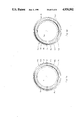
- FIGS. 1A and 1B show inside plan views of male and female annular members respectively of an anastomosis device according to a preferred embodiment of the invention.
- FIGS. 2A and 2B show cut away views of a portion of the male and female annular members respectively of FIGS. 1A and 1B.
- FIG. 3 shows a cross section taken through a radius of the mated male and female annular members of FIGS. 2A and FIG. 2B respectively.
- FIG. 4 shows a cut away view of the male and female members of FIGS. 1A and 1B as used in achieving anastomosis.
- FIGS. 5A and 5B are plan and cutaway views of a male member of an alternative embodiment of the invention.
- FIGS. 5C-5E show a variation of this embodiment.
- FIGS. 6A and 6B show male and female flexible strips respectively of an anastomosis device according to another preferred embodiment of the invention.
- FIG. 6C shows a view of the flexible male and female strips respectively of FIGS. 6A and 6B as linearly disposed.
- FIGS. 7A-7H illustrate another preferred embodiment of the invention, wherein the two main series of pins are carried on a single flexible strip.
- the present invention provides for a human tubular organ anastomosis device, for uses including but not limited to, blood vessel anastomosis, including small blood vessel micro-anastomosis, as well as the anastomosis of intestines, vas deferens, billiary duct, urethra, ureter, etc.
- the device is meant to replace conventional sutures and metal staples.
- FIGS. 1A and 1B show plan views of the male 10A and the female 10B annular members of an anastomosis device according to a preferred embodiment of the invention.
- the annular members 10A and 10B have central axes, perpendicular to the page, X and Y respectively.
- one end of a first luminal tubular organ to be anastomosed is passed through opening 11A of the male member, while the end of a second tubular organ is similarly passed through opening 11B of the female member.
- the end of each organ is disposed to point upward from the page and its luminal axis is approximately coincident with the annular member's central axis.
- Lips 12A and 12B at the inner periphery of each member have a series of pins 13A and 13B respectively disposed around the periphery thereof, and disposed approximately parallel to the central axes X and Y respectively.
- the pins in each series form a small angle, for example, approximately 15°, with the central axis, so that the exposed ends of the pins in each series lie at a slightly smaller radial distance from the central axis than do the bases of the pins.
- the radius of the interior hole in the members 10A and 10B is selected to correspond with the outer radius of the luminal members to be anastomosed.
- the outer regions of the male and female members include mating attachment elements 16A and 16B respectively in a manner described below, as well as 14A and 14B respectively, which are also described below.
- FIGS. 2A and 2B show cut away views of the male and female members respectively of FIGS. 1A and 1B. Lip 12A and jaw 15A are shown in FIG. 2A, while lip 12B and jaw 15B are shown in FIG. 2B.
- FIG. 2A shows a projecting ridge 16A around the outer periphery of the male member
- FIG. 2B shows a corresponding channel 16B around the outer periphery of the female member designed to receive projecting ridge 16A, with which it mates.
- the male and female members of this embodiment each exhibit radial symmetry, permitting the mating of the members without a specific radial orientation, as long as they are coaxial and the pins 13 on each member do not collide with one another.
- FIGS. 2A and 2B Also shown in FIGS. 2A and 2B are contact surfaces 14A and 14B respectively (shown on the upward side in FIG. 2A and on the downward side in FIG. 2B) that are in contact with one another when the attachment elements 16A and 16B are mated.
- the arrangement of these contact surfaces permits there to be maintained a gap between the lips 12A and 12B when the male and female members are mated, as described in further detail below in connection with FIG. 3.
- the surfaces are here shown as flat; other surfaces are possible, as long as the geometry is such that the surfaces are in contact with one another when the male and female members are mated.
- the attachment elements 16A and 16B are shown as a ridge and channel respectively, although other mating configurations are within the scope of the invention.
- the embodiment shown contemplates the use of resilient male and female members and also includes a retaining protrusion 18 disposed peripherally at the entrance to the channel 16B on the female member, so that when the male member's ridge 16A is pushed past the protrusion 18 of the female member, there is a very slight deformation of the members, permitting them to snap together.
- the ridge 16A is then held in place in the channel 16B by the retaining protrusion 18.
- the members can thereafter be manually unsnapped, if desired, but the geometry and materials are such that the members otherwise remain mated in usual circumstances.
- FIG. 3 shows a cross section taken through a radius of the male and female members of FIGS. 2A and 2B respectively in mated position.
- Ridge 16A in the outer region of the male member is shown disposed within the channel 16B in the outer region of the female member.
- the ridge 16A and channel 16B are configured so that the contact surface 14A is engaged against contact surface 14B, and jaws 15A and 15B form space 17, when the male and female members are mated.
- the abutting contact surfaces 14A and 14B also maintain a gap between opposing lips 12A and 12B, from which protrude the pins 13A and 13B. It will be appreciated that the gap and the space 17 allow for inflammation and growth of the tissue secured to lips 12A and 12B.
- FIG. 4 shows the male and female members 10A and 10B respectively as used in achieving anastomosis. It will be seen that the central axes of X--X and Y--Y of the mated members 10A and 10B are coincident with each other and with the luminal axes of the tubular organs 41 and 42. This figure shows that the pins 13A of the male member 10A penetrate first the exterior wall of tubular organ 42 (to which it is first attached) but then extend (as a result of mating with the female member 10B) into the wall of tubular member 41.
- the pins 13B of the female member 10B penetrate first the exterior wall of tubular organ 41 (to which it is first attached) but then extend (as a result of mating with male member 10A) into the wall of tubular member 42.
- the tubular organs are held in relation to one another by virtue of attachment elements 16A and 16B described above; in addition, however, during the mating process, the pins 13A extending through the wall of organ 42 pierce the wall of organ 41 and the pins 13B extending through the wall of organ 41 pierce the wall of organ 42.
- the angle ⁇ between the pins 13A and 13B and the central axes X--X, Y--Y is here somewhat exaggerated for purposes of illustration but is selected to facilitate penetration of the walls of the tubular members while avoiding undue or unnecessary penetration into the lumen and undue distortion of the tabular organ. It is typically preferable that the pins 13A and 13B alternate around the central axes.
- Mating can be achieved in such a way that spacing between successive pins from mating members is uniform, and, if desired, the member can be provided with a suitable keying arrangement to establish a desired relation of the two series of pins. It can be seen that no sandwiching of the organs is necessary using the present invention and that the forces present on the organs are relatively uniform around the entire anastomosed region, without interfering with the blood supply to the region. It can also be seen that the space 17 between the jaws 15A and 15B is available for inflammation and growth of the anastomosed tissue.
- the device minimizes leakage of fluid from the lumen.
- FIGS. 5A and 5B illustrate an alternative embodiment to that of the preceding figures.
- This embodiment is similar to the preceding embodiment, except that the mass of the annular member is reduced by eliminating material of the lips 12A and jaws 15A between each of the pins 13A, so that each pin 13A is mounted in relation to the outer region by means of a bridge 51.
- the male plan and cut away views 5A and 5B are shown, the female member is similarly modified. In all other major respects this embodiment resembles that of the preceding figures.
- FIG. 5C A variation of this embodiment is shown in FIG. 5C (which corresponds with FIG. 3 of the first described embodiment), wherein pins 13A emanate as before from bridge 51A of the male member 55 and not from the bridge 51B of the female member 56.
- alternate bridges of each member for example shown here is the bridge 51B of the female member 56
- an aperture 52 into which fits the pin from the mating member (for example here pin 13A from male member 55).
- each aperture 52 is formed by intersecting slits 522 and 521 so that material of the bridge at the boundary of the aperture has four pointed tips that are capable of gripping the inserted pin (13A).
- bridges 51B and 51A in which is shown a top view of mated members 56 and 55 (with the luminal organ in cross section), the structure of bridges 51B and 51A is such that the anastomosed tissue need be only partially everted and there is ample space in which the anastomosed tissue may grow and heal.
- Another embodiment of the invention utilizes a pair of flexible strips in a manner analogous to the annular members described above.
- a male flexible strip is wrapped around the end of one of the tubular organs to be anastomosed as shown in FIG. 6A and a female flexible strip is wrapped around the end of the other of the tubular organs to be anastomosed as shown in FIG. 6B.
- the strips are held in place, prior to mating, with pins 64A and 64B.
- the strips are then mated in the general manner described above in connection with FIGS. 2, 3, and 4.
- the mated strips, uncurled and in a perspective cut away without tissue are shown in FIG. 6C.
- the male and female strips have respectively lips 61A and 61B, jaws 62A and 62B, contact surfaces 63A and 63B, and attachment elements 65 and 66 corresponding to similarly named items in the male and female annular members described above.
- the attachment element is a ridge 65 in the male and a channel 66 in the female.
- the channel includes a retaining protrusion as described above in connection with the annular members.
- FIGS. 7A through 7H illustrate another embodiment of the invention in which a strip 71 of flexible material carries both the series of pins used to initially engage and hold a first tubular organ and the series of pins used to initially engage and hold a second tubular organ.
- a first series of pins 72 is mounted across the strip so that their bases are attached along the left edge of the strip and their exposed ends point toward the right edge of the strip.
- a second series of pins 74 is mounted across the strip on the same side of the stripped in the alternation with, the first series, oriented so that their bases are attached along the right edge of the strip and their exposed ends point toward the left edge of the strip.
- alternation with each pin along the left edge is a short (e.g.
- FIGS. 7B through 7D are inverted horizontal cross sections taken through planes B--B, C--C and D--D respectively of FIG. 7A. It can be seen that the pins 72 and 74 are curved to facilitate engagement in the tubular organs and fastening of the pins in the manner described below.
- a series of buttom holes 75 and 78 appear along the left and right sides respectively of the strip in alternation with pins 77 and 76.
- the strip is first folded approximately along midline Z--Z into a shape the type illustrated in cross section in FIG. 7F.
- pins 74 are inserted around the end of a first tubular organ in the manner described above with respect to FIG. 6, and the pins 72 are inserted around the end of a second tubular organ.
- the strip 71 is also unfolded to produce anastomosis as shown in cross section FIG. 7G of the first organ 78 and the second organ 79.
- the exposed ends of the pins extend, from the walls of the organ into which they were initially inserted, into the walls of the other organ.
- the short pins 76 and 77 engage into the walls of tubular organs 78 and 79 respectively to prevent movement of the tubular organs with respect to the device or each other.
- FIG. 7H shows a cut away view of the anastomosis device of this embodiment after anastomosis has been achieved.
- male and female members of each embodiment may be made of an absorbable material such as polyglycolic or polylactic compounds.
Abstract
Description
Claims (20)
Priority Applications (10)
| Application Number | Priority Date | Filing Date | Title |
|---|---|---|---|
| US07/303,326 US4930502A (en) | 1989-01-26 | 1989-01-26 | Anastomosis device |
| EP90902481A EP0455701B1 (en) | 1989-01-26 | 1990-01-25 | Anastomosis device |
| CN90100996A CN1023374C (en) | 1989-01-26 | 1990-01-25 | Anastomosis device |
| PCT/US1990/000375 WO1990008509A1 (en) | 1989-01-26 | 1990-01-25 | Anastomosis device |
| DE69022031T DE69022031T2 (en) | 1989-01-26 | 1990-01-25 | ANASTOMOSIS ARRANGEMENT. |
| US07/472,209 US4997439A (en) | 1989-01-26 | 1990-01-26 | Surgical closure or anastomotic device |
| US07/629,608 US5089008A (en) | 1989-01-26 | 1990-12-18 | Surgical closure means for anastomotic device |
| US07/735,950 US5123908A (en) | 1989-01-26 | 1991-07-25 | Anastomotic device |
| US07/902,210 US5250057A (en) | 1989-01-26 | 1992-06-22 | Anastomotic device |
| US08/037,399 US5336233A (en) | 1989-01-26 | 1993-03-26 | Anastomotic device |
Applications Claiming Priority (1)
| Application Number | Priority Date | Filing Date | Title |
|---|---|---|---|
| US07/303,326 US4930502A (en) | 1989-01-26 | 1989-01-26 | Anastomosis device |
Related Child Applications (1)
| Application Number | Title | Priority Date | Filing Date |
|---|---|---|---|
| US07/472,209 Continuation-In-Part US4997439A (en) | 1989-01-26 | 1990-01-26 | Surgical closure or anastomotic device |
Publications (1)
| Publication Number | Publication Date |
|---|---|
| US4930502A true US4930502A (en) | 1990-06-05 |
Family
ID=23171551
Family Applications (1)
| Application Number | Title | Priority Date | Filing Date |
|---|---|---|---|
| US07/303,326 Expired - Fee Related US4930502A (en) | 1989-01-26 | 1989-01-26 | Anastomosis device |
Country Status (5)
| Country | Link |
|---|---|
| US (1) | US4930502A (en) |
| EP (1) | EP0455701B1 (en) |
| CN (1) | CN1023374C (en) |
| DE (1) | DE69022031T2 (en) |
| WO (1) | WO1990008509A1 (en) |
Cited By (50)
| Publication number | Priority date | Publication date | Assignee | Title |
|---|---|---|---|---|
| US5158566A (en) * | 1990-01-15 | 1992-10-27 | Francesco Pianetti | Metal clip with four points which converge in pairs, for the simultaneous suture of the cutaneous tissue and subcutaneous tissue |
| US5312456A (en) * | 1991-01-31 | 1994-05-17 | Carnegie Mellon University | Micromechanical barb and method for making the same |
| US5549621A (en) * | 1993-05-14 | 1996-08-27 | Byron C. Sutherland | Apparatus and method for performing vertical banded gastroplasty |
| US5868763A (en) * | 1996-09-16 | 1999-02-09 | Guidant Corporation | Means and methods for performing an anastomosis |
| US5922022A (en) * | 1997-09-04 | 1999-07-13 | Kensey Nash Corporation | Bifurcated connector system for coronary bypass grafts and methods of use |
| US5993464A (en) * | 1998-01-23 | 1999-11-30 | Ethicon Endo-Surgery, Inc. | Surgical stapling instrument |
| US6015416A (en) * | 1998-02-26 | 2000-01-18 | Ethicon Endo-Surgery, Inc. | Surgical anastomosis instrument |
| US6017352A (en) * | 1997-09-04 | 2000-01-25 | Kensey Nash Corporation | Systems for intravascular procedures and methods of use |
| US6019788A (en) * | 1996-11-08 | 2000-02-01 | Gore Enterprise Holdings, Inc. | Vascular shunt graft and junction for same |
| US6030395A (en) * | 1997-05-22 | 2000-02-29 | Kensey Nash Corporation | Anastomosis connection system |
| US6063114A (en) * | 1997-09-04 | 2000-05-16 | Kensey Nash Corporation | Connector system for vessels, ducts, lumens or hollow organs and methods of use |
| US6066144A (en) * | 1997-10-07 | 2000-05-23 | Ethicon Endo-Surgery, Inc. | Surgical anastomosis method |
| WO2000033745A1 (en) * | 1998-12-07 | 2000-06-15 | Guidant Corporation | Means and method for performing an anastomosis |
| US6488692B1 (en) | 1996-09-16 | 2002-12-03 | Origin Medsystems, Inc. | Access and cannulation device and method for rapidly placing same and for rapidly closing same in minimally invasive surgery |
| US6514263B1 (en) | 2000-08-30 | 2003-02-04 | Ethicon Endo-Surgery, Inc. | Helical needle and suture combination having a strain relief element |
| US6520973B1 (en) | 2000-08-30 | 2003-02-18 | Ethicon Endo-Surgery, Inc. | Anastomosis device having an improved needle driver |
| US6530932B1 (en) | 2000-08-30 | 2003-03-11 | Ethicon Endo-Surgery, Inc. | Anastomosis device having improved tissue presentation |
| US6565581B1 (en) | 1996-09-16 | 2003-05-20 | Origin Medsystems, Inc. | Apparatus and method for performing an anastomosis |
| US6613058B1 (en) | 2000-08-30 | 2003-09-02 | Ethicon Endo-Surgery, Inc. | Anastomosis device having needle receiver for capturing the needle |
| US20030208214A1 (en) * | 2000-03-20 | 2003-11-06 | Amir Loshakove | Anastomotic connector and graft expander for mounting a graft |
| US20040073247A1 (en) * | 1998-05-29 | 2004-04-15 | By-Pass, Inc. | Method and apparatus for forming apertures in blood vessels |
| US6726704B1 (en) | 1998-05-29 | 2004-04-27 | By-Pass, Inc. | Advanced closure device |
| US20040087985A1 (en) * | 1999-03-19 | 2004-05-06 | Amir Loshakove | Graft and connector delivery |
| US20040097973A1 (en) * | 2000-03-20 | 2004-05-20 | Amir Loshakove | Transvascular bybass method and system |
| US6811555B1 (en) | 1996-09-16 | 2004-11-02 | Origin Medsystems, Inc. | Method and apparatus for performing anastomosis with eversion of tissue edges and joining of exposed intima of the everted tissue |
| US6890338B1 (en) | 2001-02-27 | 2005-05-10 | Origin Medsystems, Inc. | Method and apparatus for performing anastomosis using ring having tines with weak sections |
| US20050101983A1 (en) * | 1998-05-29 | 2005-05-12 | By-Pass,Inc. | Method and apparatus for forming apertures in blood vessels |
| US20050149075A1 (en) * | 2003-12-23 | 2005-07-07 | I. & S. - Idee & Sviluppo S.R.L. | Device and method for anastomosis |
| US20050149073A1 (en) * | 2003-12-17 | 2005-07-07 | Arani Djavad T. | Mechanisms and methods used in the anastomosis of biological conduits |
| US20050283188A1 (en) * | 1998-05-29 | 2005-12-22 | By-Pass, Inc. | Vascular closure device |
| US6979338B1 (en) | 1998-05-29 | 2005-12-27 | By-Pass Inc. | Low profile anastomosis connector |
| US7022131B1 (en) | 1998-05-29 | 2006-04-04 | By-Pass Inc. | Methods and devices for vascular surgery |
| US7060084B1 (en) * | 1998-05-29 | 2006-06-13 | By-Pass, Inc. | Vascular closure device |
| US7063711B1 (en) | 1998-05-29 | 2006-06-20 | By-Pass, Inc. | Vascular surgery |
| EP1773212A1 (en) * | 2004-07-22 | 2007-04-18 | Vascon AB | Anastomosis device and method |
| US20070186268A1 (en) * | 2004-03-09 | 2007-08-09 | Mcneely David L | Cross-encoding of information in independent channels |
| US20070239195A1 (en) * | 2004-05-18 | 2007-10-11 | Nocca David J | Adjustable Prosthetic Band |
| US20080132915A1 (en) * | 2002-09-13 | 2008-06-05 | Buckman Robert F | Method and apparatus for vascular and visceral clipping |
| US7396359B1 (en) * | 1998-05-29 | 2008-07-08 | Bypass, Inc. | Vascular port device |
| US20090043319A1 (en) * | 2007-08-08 | 2009-02-12 | Regner Justin L | Pancreatic-enteric fistulary catheterization system |
| US20090275961A1 (en) * | 2008-05-01 | 2009-11-05 | Harris Jason L | Gastric volume reduction using anterior to posterior wall junctions |
| US20100063520A1 (en) * | 2006-03-07 | 2010-03-11 | Federico Bilotti | Anastomotic device |
| US20100121428A1 (en) * | 2006-10-26 | 2010-05-13 | Vascusnap B.V. | Vascular prosthesis |
| US7758614B2 (en) | 1998-07-08 | 2010-07-20 | Tornier, Inc. | Coupling member for knotless sutures and ligatures |
| US20100286717A1 (en) * | 2002-04-17 | 2010-11-11 | Tyco Healthcare Group Lp | Method and Apparatus for Anastomosis Including an Expandable Anchor |
| US20130110140A1 (en) * | 2009-10-30 | 2013-05-02 | National Yang-Ming University | Anastomosis system |
| US8475477B2 (en) | 2004-10-19 | 2013-07-02 | Newman Medical Kft | Vascular graft |
| CN106983916A (en) * | 2017-04-26 | 2017-07-28 | 温州生物材料与工程研究所 | Biodegradable no-station pole canopy isolates alimentary canal capsule-type stapler and preparation method |
| US20210145624A1 (en) * | 2015-09-15 | 2021-05-20 | Savage Medical, Inc. | Devices and methods for anchoring a sheath in a tissue cavity |
| US11751876B2 (en) | 2019-05-07 | 2023-09-12 | Easyflomicro Inc. | Apparatuses for anastomosis of tubular vessels and related methods |
Families Citing this family (11)
| Publication number | Priority date | Publication date | Assignee | Title |
|---|---|---|---|---|
| US5197649A (en) * | 1991-10-29 | 1993-03-30 | The Trustees Of Columbia University In The City Of New York | Gastrointestinal endoscoptic stapler |
| CN1327815C (en) * | 2004-04-29 | 2007-07-25 | 胡晓旻 | Distant end blood vessel anastomat for coronary artery bypass |
| US20110295181A1 (en) | 2008-03-05 | 2011-12-01 | Hemosphere, Inc. | Implantable and removable customizable body conduit |
| CN103813817A (en) | 2011-09-06 | 2014-05-21 | 海默斯菲尔有限公司 | Vascular access system with connector |
| ES2689019T3 (en) * | 2013-08-13 | 2018-11-08 | Merit Medical Systems, Inc. | Systems and methods for a fluid transport conduit of a vascular access system |
| WO2015094514A1 (en) | 2013-12-20 | 2015-06-25 | Cryolife, Inc. | Vascular access system with reinforcement member |
| CN104905836B (en) * | 2014-03-13 | 2018-08-28 | 臧运金 | Chimeric combination formula vascular anastomosis device |
| WO2018089625A2 (en) | 2016-11-10 | 2018-05-17 | Merit Medical Systems, Inc. | Anchor device for vascular anastomosis |
| US11026704B2 (en) | 2017-03-06 | 2021-06-08 | Merit Medical Systems, Inc. | Vascular access assembly declotting systems and methods |
| US11331458B2 (en) | 2017-10-31 | 2022-05-17 | Merit Medical Systems, Inc. | Subcutaneous vascular assemblies for improving blood flow and related devices and methods |
| EP3932439A4 (en) * | 2019-03-28 | 2022-04-27 | TERUMO Kabushiki Kaisha | Medical device |
Citations (3)
| Publication number | Priority date | Publication date | Assignee | Title |
|---|---|---|---|---|
| US2638901A (en) * | 1951-07-30 | 1953-05-19 | Everett D Sugarbaker | Surgical clamp |
| US4523592A (en) * | 1983-04-25 | 1985-06-18 | Rollin K. Daniel P.S.C. | Anastomotic coupling means capable of end-to-end and end-to-side anastomosis |
| US4747407A (en) * | 1985-09-03 | 1988-05-31 | The Field Surgery Research Department of the Third Military Medical University | Blood vessel anastomat |
Family Cites Families (4)
| Publication number | Priority date | Publication date | Assignee | Title |
|---|---|---|---|---|
| US3254650A (en) * | 1962-03-19 | 1966-06-07 | Michael B Collito | Surgical anastomosis methods and devices |
| US3221746A (en) * | 1963-01-25 | 1965-12-07 | Noble John William | Surgical connecting device |
| US4467804A (en) * | 1980-10-20 | 1984-08-28 | American Cyanamid Company | Anastomotic device |
| JPS60501543A (en) * | 1983-06-15 | 1985-09-19 | シエンク,ロバ−ト・ロイ | Methods and devices for joining anatomical structures |
-
1989
- 1989-01-26 US US07/303,326 patent/US4930502A/en not_active Expired - Fee Related
-
1990
- 1990-01-25 CN CN90100996A patent/CN1023374C/en not_active Expired - Fee Related
- 1990-01-25 EP EP90902481A patent/EP0455701B1/en not_active Expired - Lifetime
- 1990-01-25 DE DE69022031T patent/DE69022031T2/en not_active Expired - Fee Related
- 1990-01-25 WO PCT/US1990/000375 patent/WO1990008509A1/en active IP Right Grant
Patent Citations (3)
| Publication number | Priority date | Publication date | Assignee | Title |
|---|---|---|---|---|
| US2638901A (en) * | 1951-07-30 | 1953-05-19 | Everett D Sugarbaker | Surgical clamp |
| US4523592A (en) * | 1983-04-25 | 1985-06-18 | Rollin K. Daniel P.S.C. | Anastomotic coupling means capable of end-to-end and end-to-side anastomosis |
| US4747407A (en) * | 1985-09-03 | 1988-05-31 | The Field Surgery Research Department of the Third Military Medical University | Blood vessel anastomat |
Cited By (86)
| Publication number | Priority date | Publication date | Assignee | Title |
|---|---|---|---|---|
| US5158566A (en) * | 1990-01-15 | 1992-10-27 | Francesco Pianetti | Metal clip with four points which converge in pairs, for the simultaneous suture of the cutaneous tissue and subcutaneous tissue |
| US5312456A (en) * | 1991-01-31 | 1994-05-17 | Carnegie Mellon University | Micromechanical barb and method for making the same |
| US5549621A (en) * | 1993-05-14 | 1996-08-27 | Byron C. Sutherland | Apparatus and method for performing vertical banded gastroplasty |
| US6811555B1 (en) | 1996-09-16 | 2004-11-02 | Origin Medsystems, Inc. | Method and apparatus for performing anastomosis with eversion of tissue edges and joining of exposed intima of the everted tissue |
| US6884251B2 (en) | 1996-09-16 | 2005-04-26 | Origin Medsystems, Inc. | Apparatus and method for performing an anastomosis |
| US20040220597A1 (en) * | 1996-09-16 | 2004-11-04 | Willis Geoffrey H. | Method and apparatus for performing anastomosis with eversion of tissue edges and joining of exposed intima of the everted tissue |
| US6190397B1 (en) | 1996-09-16 | 2001-02-20 | Origin Medsystems, Inc. | Means and method for performing an anastomosis |
| US6652543B2 (en) | 1996-09-16 | 2003-11-25 | Origin Medsystems, Inc. | Means and method for performing an anastomosis |
| US7497865B2 (en) | 1996-09-16 | 2009-03-03 | Maquet Cardiovascular, Llc | Method and apparatus for performing anastomosis with eversion of tissue edges and joining of exposed intima of the everted tissue |
| US6565581B1 (en) | 1996-09-16 | 2003-05-20 | Origin Medsystems, Inc. | Apparatus and method for performing an anastomosis |
| US5868763A (en) * | 1996-09-16 | 1999-02-09 | Guidant Corporation | Means and methods for performing an anastomosis |
| US6488692B1 (en) | 1996-09-16 | 2002-12-03 | Origin Medsystems, Inc. | Access and cannulation device and method for rapidly placing same and for rapidly closing same in minimally invasive surgery |
| US6254617B1 (en) | 1996-09-16 | 2001-07-03 | Origin Medsystems, Inc. | Means and method for performing an anastomosis |
| US6241742B1 (en) | 1996-09-16 | 2001-06-05 | Origin Medsystems, Inc. | Means and method for performing an anastomosis |
| US6019788A (en) * | 1996-11-08 | 2000-02-01 | Gore Enterprise Holdings, Inc. | Vascular shunt graft and junction for same |
| US6402767B1 (en) | 1997-05-22 | 2002-06-11 | Kensey Nash Corporation | Anastomosis connection system and method of use |
| US6056762A (en) * | 1997-05-22 | 2000-05-02 | Kensey Nash Corporation | Anastomosis system and method of use |
| US6030395A (en) * | 1997-05-22 | 2000-02-29 | Kensey Nash Corporation | Anastomosis connection system |
| US6036705A (en) * | 1997-05-22 | 2000-03-14 | Kensey Nash Corporation | Anastomosis connection system and method of use |
| US6017352A (en) * | 1997-09-04 | 2000-01-25 | Kensey Nash Corporation | Systems for intravascular procedures and methods of use |
| US20070293881A1 (en) * | 1997-09-04 | 2007-12-20 | Nash John E | Surgical connector systems and methods of use |
| US6063114A (en) * | 1997-09-04 | 2000-05-16 | Kensey Nash Corporation | Connector system for vessels, ducts, lumens or hollow organs and methods of use |
| US20100217290A1 (en) * | 1997-09-04 | 2010-08-26 | Nash John E | Surgical connector systems and methods of use |
| US6350280B1 (en) | 1997-09-04 | 2002-02-26 | Kensey Nash Corporation | Surgical connector systems and methods of use |
| US7695483B2 (en) | 1997-09-04 | 2010-04-13 | Kensey Nash Corporation | Surgical connector systems and methods of use |
| US8377080B2 (en) | 1997-09-04 | 2013-02-19 | Kensey Nash Corporation | Surgical connector systems and methods of use |
| US6923820B1 (en) | 1997-09-04 | 2005-08-02 | Kensey Nash Corporation | Surgical connector systems and methods of use |
| US5922022A (en) * | 1997-09-04 | 1999-07-13 | Kensey Nash Corporation | Bifurcated connector system for coronary bypass grafts and methods of use |
| US20050245946A1 (en) * | 1997-09-04 | 2005-11-03 | Nash John E | Surgical connector systems and methods of use |
| US7264624B2 (en) | 1997-09-04 | 2007-09-04 | Kensey Nash Corporation | Surgical connector systems and methods of use |
| US6066144A (en) * | 1997-10-07 | 2000-05-23 | Ethicon Endo-Surgery, Inc. | Surgical anastomosis method |
| US5993464A (en) * | 1998-01-23 | 1999-11-30 | Ethicon Endo-Surgery, Inc. | Surgical stapling instrument |
| US6015416A (en) * | 1998-02-26 | 2000-01-18 | Ethicon Endo-Surgery, Inc. | Surgical anastomosis instrument |
| US6187019B1 (en) | 1998-02-26 | 2001-02-13 | Ethicon Endo-Surgery, Inc. | Surgical anastomosis instrument |
| US6726704B1 (en) | 1998-05-29 | 2004-04-27 | By-Pass, Inc. | Advanced closure device |
| US7063711B1 (en) | 1998-05-29 | 2006-06-20 | By-Pass, Inc. | Vascular surgery |
| US20040073247A1 (en) * | 1998-05-29 | 2004-04-15 | By-Pass, Inc. | Method and apparatus for forming apertures in blood vessels |
| US7060084B1 (en) * | 1998-05-29 | 2006-06-13 | By-Pass, Inc. | Vascular closure device |
| US20050101983A1 (en) * | 1998-05-29 | 2005-05-12 | By-Pass,Inc. | Method and apparatus for forming apertures in blood vessels |
| US7022131B1 (en) | 1998-05-29 | 2006-04-04 | By-Pass Inc. | Methods and devices for vascular surgery |
| US6979338B1 (en) | 1998-05-29 | 2005-12-27 | By-Pass Inc. | Low profile anastomosis connector |
| US20050283188A1 (en) * | 1998-05-29 | 2005-12-22 | By-Pass, Inc. | Vascular closure device |
| US7396359B1 (en) * | 1998-05-29 | 2008-07-08 | Bypass, Inc. | Vascular port device |
| US7758614B2 (en) | 1998-07-08 | 2010-07-20 | Tornier, Inc. | Coupling member for knotless sutures and ligatures |
| WO2000033745A1 (en) * | 1998-12-07 | 2000-06-15 | Guidant Corporation | Means and method for performing an anastomosis |
| US20040087985A1 (en) * | 1999-03-19 | 2004-05-06 | Amir Loshakove | Graft and connector delivery |
| US20040092975A1 (en) * | 1999-03-19 | 2004-05-13 | Amir Loshakove | Anastomotic connection system |
| US20040097973A1 (en) * | 2000-03-20 | 2004-05-20 | Amir Loshakove | Transvascular bybass method and system |
| US20030208214A1 (en) * | 2000-03-20 | 2003-11-06 | Amir Loshakove | Anastomotic connector and graft expander for mounting a graft |
| US6520973B1 (en) | 2000-08-30 | 2003-02-18 | Ethicon Endo-Surgery, Inc. | Anastomosis device having an improved needle driver |
| US6613058B1 (en) | 2000-08-30 | 2003-09-02 | Ethicon Endo-Surgery, Inc. | Anastomosis device having needle receiver for capturing the needle |
| US6514263B1 (en) | 2000-08-30 | 2003-02-04 | Ethicon Endo-Surgery, Inc. | Helical needle and suture combination having a strain relief element |
| US6530932B1 (en) | 2000-08-30 | 2003-03-11 | Ethicon Endo-Surgery, Inc. | Anastomosis device having improved tissue presentation |
| US6890338B1 (en) | 2001-02-27 | 2005-05-10 | Origin Medsystems, Inc. | Method and apparatus for performing anastomosis using ring having tines with weak sections |
| US20100286717A1 (en) * | 2002-04-17 | 2010-11-11 | Tyco Healthcare Group Lp | Method and Apparatus for Anastomosis Including an Expandable Anchor |
| US8480694B2 (en) * | 2002-04-17 | 2013-07-09 | Covidien Lp | Method and apparatus for anastomosis including an expandable anchor |
| US20080132915A1 (en) * | 2002-09-13 | 2008-06-05 | Buckman Robert F | Method and apparatus for vascular and visceral clipping |
| US8187290B2 (en) * | 2002-09-13 | 2012-05-29 | Damage Control Surgical Technologies, Inc. | Method and apparatus for vascular and visceral clipping |
| US20050149073A1 (en) * | 2003-12-17 | 2005-07-07 | Arani Djavad T. | Mechanisms and methods used in the anastomosis of biological conduits |
| US7837697B2 (en) | 2003-12-23 | 2010-11-23 | Newman Medical Kft | Device and method for anastomosis |
| US20110066171A1 (en) * | 2003-12-23 | 2011-03-17 | Enzo Borghi | Device and method for anastomosis |
| US8480695B2 (en) | 2003-12-23 | 2013-07-09 | Newman Medical Kft | Device and method for anastomosis |
| WO2005063130A2 (en) | 2003-12-23 | 2005-07-14 | Blue Sky Financial S.A. | Device and method for anastomosis |
| US20050149075A1 (en) * | 2003-12-23 | 2005-07-07 | I. & S. - Idee & Sviluppo S.R.L. | Device and method for anastomosis |
| WO2005063130A3 (en) * | 2003-12-23 | 2005-10-13 | I & S Idee & Sviluppo S R L | Device and method for anastomosis |
| US20070186268A1 (en) * | 2004-03-09 | 2007-08-09 | Mcneely David L | Cross-encoding of information in independent channels |
| US7489730B2 (en) * | 2004-03-09 | 2009-02-10 | Thomson Licensing | Cross-encoding of information in independent channels |
| US20070239195A1 (en) * | 2004-05-18 | 2007-10-11 | Nocca David J | Adjustable Prosthetic Band |
| EP1773212A1 (en) * | 2004-07-22 | 2007-04-18 | Vascon AB | Anastomosis device and method |
| EP1773212A4 (en) * | 2004-07-22 | 2012-02-29 | Prozeo Vascular Implant Ab | Anastomosis device and method |
| US8475477B2 (en) | 2004-10-19 | 2013-07-02 | Newman Medical Kft | Vascular graft |
| US8932304B2 (en) | 2004-10-19 | 2015-01-13 | Newman Medical Kft | Vascular graft |
| US8795300B2 (en) * | 2006-03-07 | 2014-08-05 | Ethicon Endo-Surgery, Inc. | Anastomotic device |
| US20100063520A1 (en) * | 2006-03-07 | 2010-03-11 | Federico Bilotti | Anastomotic device |
| US9504468B2 (en) * | 2006-10-26 | 2016-11-29 | Vascu-Snap B.V. | Vascular prosthesis |
| US20100121428A1 (en) * | 2006-10-26 | 2010-05-13 | Vascusnap B.V. | Vascular prosthesis |
| US7850706B2 (en) * | 2007-08-08 | 2010-12-14 | Board Of Trustees Of The University Of Arkansas | Pancreatic-enteric fistulary catheterization system |
| US20090043319A1 (en) * | 2007-08-08 | 2009-02-12 | Regner Justin L | Pancreatic-enteric fistulary catheterization system |
| US20090275961A1 (en) * | 2008-05-01 | 2009-11-05 | Harris Jason L | Gastric volume reduction using anterior to posterior wall junctions |
| US20130110140A1 (en) * | 2009-10-30 | 2013-05-02 | National Yang-Ming University | Anastomosis system |
| US20210145624A1 (en) * | 2015-09-15 | 2021-05-20 | Savage Medical, Inc. | Devices and methods for anchoring a sheath in a tissue cavity |
| US20230372139A1 (en) * | 2015-09-15 | 2023-11-23 | Savage Medical, Inc. | Devices and methods for anchoring a sheath in a tissue cavity |
| US11903865B2 (en) * | 2015-09-15 | 2024-02-20 | Savage Medical, Inc. | Devices and methods for anchoring a sheath in a tissue cavity |
| CN106983916A (en) * | 2017-04-26 | 2017-07-28 | 温州生物材料与工程研究所 | Biodegradable no-station pole canopy isolates alimentary canal capsule-type stapler and preparation method |
| CN106983916B (en) * | 2017-04-26 | 2022-04-19 | 温州生物材料与工程研究所 | Biodegradable tension-free isolated alimentary tract capsule type anastomat and preparation method |
| US11751876B2 (en) | 2019-05-07 | 2023-09-12 | Easyflomicro Inc. | Apparatuses for anastomosis of tubular vessels and related methods |
Also Published As
| Publication number | Publication date |
|---|---|
| EP0455701A4 (en) | 1992-08-05 |
| DE69022031D1 (en) | 1995-10-05 |
| CN1046668A (en) | 1990-11-07 |
| DE69022031T2 (en) | 1996-04-18 |
| WO1990008509A1 (en) | 1990-08-09 |
| EP0455701A1 (en) | 1991-11-13 |
| EP0455701B1 (en) | 1995-08-30 |
| CN1023374C (en) | 1994-01-05 |
Similar Documents
| Publication | Publication Date | Title |
|---|---|---|
| US4930502A (en) | Anastomosis device | |
| US4523592A (en) | Anastomotic coupling means capable of end-to-end and end-to-side anastomosis | |
| US4747407A (en) | Blood vessel anastomat | |
| US4214586A (en) | Anastomotic coupling device | |
| US4593693A (en) | Methods and apparatus for anastomosing living vessels | |
| EP1281356A2 (en) | Blood vessel connecting instrument | |
| AU755390B2 (en) | Transanal anastomosis ring insertion device | |
| US8182498B2 (en) | Mechanical anastomosis system for hollow structures | |
| US4854318A (en) | Blood vessel holder and method of using in anastomosis | |
| US5037428A (en) | Vessel approximation and alignment device | |
| US6682540B1 (en) | Apparatus and method for placing multiple sutures | |
| US6036704A (en) | Anastomosis apparatus and method for anastomosing an anatomical tubular structure | |
| EP0158316A2 (en) | Anastomosis devices and kit | |
| US20180214150A1 (en) | Magnetic tissue compression device with backup mechanical latch | |
| US7018387B2 (en) | Mechanical anastomosis system for hollow structures | |
| US20220273311A1 (en) | Apparatuses for anastomosis of tubular vessels and related methods | |
| US20040002721A1 (en) | Method and apparatus for performing end-to-end and end-to-side anastomosis with eversion of tissue edges | |
| US20040181244A1 (en) | Vascular anastomosis device | |
| CN111904517B (en) | Blood vessel anastomat | |
| CN215960083U (en) | Tissue cavity anastomosis ring | |
| WO2020078264A1 (en) | Small lumen anastomat and use method therefor | |
| CN110811729A (en) | Buckle formula blood vessel anastomosis device | |
| MXPA02004493A (en) | Apparatus and method for placing multiple sutures during anastomosis. | |
| CN211433106U (en) | Buckle formula blood vessel anastomosis device | |
| CN217611213U (en) | Novel closed blood vessel anastomat of medicine carrying |
Legal Events
| Date | Code | Title | Description |
|---|---|---|---|
| FEPP | Fee payment procedure |
Free format text: PAYOR NUMBER ASSIGNED (ORIGINAL EVENT CODE: ASPN); ENTITY STATUS OF PATENT OWNER: SMALL ENTITY |
|
| FPAY | Fee payment |
Year of fee payment: 4 |
|
| FEPP | Fee payment procedure |
Free format text: PAYER NUMBER DE-ASSIGNED (ORIGINAL EVENT CODE: RMPN); ENTITY STATUS OF PATENT OWNER: SMALL ENTITY Free format text: PAYOR NUMBER ASSIGNED (ORIGINAL EVENT CODE: ASPN); ENTITY STATUS OF PATENT OWNER: SMALL ENTITY |
|
| AS | Assignment |
Owner name: CHEN, LANA S., CONNECTICUT Free format text: ASSIGNMENT OF ASSIGNORS INTEREST;ASSIGNOR:CHEN, FUSEN H.;REEL/FRAME:008412/0366 Effective date: 19951227 |
|
| FPAY | Fee payment |
Year of fee payment: 8 |
|
| REMI | Maintenance fee reminder mailed | ||
| LAPS | Lapse for failure to pay maintenance fees | ||
| STCH | Information on status: patent discontinuation |
Free format text: PATENT EXPIRED DUE TO NONPAYMENT OF MAINTENANCE FEES UNDER 37 CFR 1.362 |
|
| FP | Lapsed due to failure to pay maintenance fee |
Effective date: 20020605 |