US4930532A - Beaker holder for use with ultrasonic cleaning device - Google Patents
Beaker holder for use with ultrasonic cleaning device Download PDFInfo
- Publication number
- US4930532A US4930532A US07/312,033 US31203389A US4930532A US 4930532 A US4930532 A US 4930532A US 31203389 A US31203389 A US 31203389A US 4930532 A US4930532 A US 4930532A
- Authority
- US
- United States
- Prior art keywords
- beaker
- holder
- ring
- container
- shaped member
- Prior art date
- Legal status (The legal status is an assumption and is not a legal conclusion. Google has not performed a legal analysis and makes no representation as to the accuracy of the status listed.)
- Expired - Fee Related
Links
- 238000004506 ultrasonic cleaning Methods 0.000 title claims abstract description 23
- 238000004140 cleaning Methods 0.000 claims abstract description 27
- 239000007788 liquid Substances 0.000 claims description 17
- 230000000284 resting effect Effects 0.000 claims description 2
- 239000000463 material Substances 0.000 description 3
- 230000005855 radiation Effects 0.000 description 3
- 238000013016 damping Methods 0.000 description 2
- 239000011521 glass Substances 0.000 description 2
- XLYOFNOQVPJJNP-UHFFFAOYSA-N water Substances O XLYOFNOQVPJJNP-UHFFFAOYSA-N 0.000 description 2
- 239000002253 acid Substances 0.000 description 1
- 239000003518 caustics Substances 0.000 description 1
- 239000003599 detergent Substances 0.000 description 1
- 239000002184 metal Substances 0.000 description 1
- 230000004048 modification Effects 0.000 description 1
- 238000012986 modification Methods 0.000 description 1
- 230000002093 peripheral effect Effects 0.000 description 1
- 230000000717 retained effect Effects 0.000 description 1
- 125000006850 spacer group Chemical group 0.000 description 1
- 229910001220 stainless steel Inorganic materials 0.000 description 1
- 239000010935 stainless steel Substances 0.000 description 1
- 230000001954 sterilising effect Effects 0.000 description 1
- 238000004659 sterilization and disinfection Methods 0.000 description 1
Images


Classifications
-
- A—HUMAN NECESSITIES
- A61—MEDICAL OR VETERINARY SCIENCE; HYGIENE
- A61C—DENTISTRY; APPARATUS OR METHODS FOR ORAL OR DENTAL HYGIENE
- A61C19/00—Dental auxiliary appliances
- A61C19/002—Cleaning devices specially adapted for dental instruments
Definitions
- the present invention relates to cleaning devices for cleaning medical and dental tools in general, and more particularly to a holder for supporting a beaker immersed in an ultrasonic cleaning device filled with a suitable cleaning liquid.
- Ultrasonic cleaning devices for cleaning medical, dental instruments, dentures and the like have been known and typically include a housing with a container which holds a liquid and a transducer to generate and amplify vibrations through the liquid when the transducer is actuated.
- Medical or dental instruments or dentures are usually placed in a glass beaker in which a cleaning solution is placed. The beaker is then immersed into the container in the ultrasonic cleaning device. Ultrasonic vibrations pass through the liquid in the container and into the beaker. The vibrations shake loose the dirt on the instrument which can then be cleaned within the cleaning solution.
- the ultrasonic transducer produces standing waves which emanate into the container
- these templates or holders have included blocks or spacers to space the beaker from the bottom.
- Yet another object of this invention is to provide a beaker holder which can be adjusted to different sized beakers.
- Still yet a further object of the present invention is to provide a beaker holder which would firmly and reliably support a beaker in a spaced relationship from the bottom of the container of an ultrasonic cleaning device.
- a beaker holder for supporting a beaker within a container filled with a liquid subjected to ultrasonic waves.
- the beaker holder comprises a ring-shaped member which may typically be made of plastic material, and a metallic wire support member which is detachably-connectable to the ring-shaped member.
- the holder is inserted in the container of the ultrasonic cleaning device wherein ultrasonic radiation is generated into the liquid in the container.
- the ultrasonic waves are transmitted through the walls of the container and through the liquid into the beaker in which there is a cleaning solution.
- the ring-shaped member has a split with a circumferential section removed, whereby, the ring-shaped member being flexible, can have its inner diameter adjusted to receive beakers of different diameters.
- inwardly extending spaced-apart projections or tabs are formed on the inner surface of the ring-shaped member. These tabs grip the exterior of the beaker and hold it. Also, they space the beaker from the inner periphery of the ring to accommodate the flow of condensing liquid occurring in the operation of the ultrasonic cleaning device, and feed the liquid back into the container.
- the wire support member is of U-shaped configurations with two vertical legs and a base portion extending therebetween.
- the wire supports the beaker above the bottom of the container to prevent dampening of the ultrasonic waves at the bottom of the container.
- the width of the beaker ring itself also serves to space the beaker from the sides of the container to prevent dampening of the waves at the sides of the container.
- two diametrically opposing bent portions extending away from each other are formed on the free ends of the legs of the wire support element.
- the bent portions are received in L-shaped slots formed in the ring-shaped member to detachably-connect the wire support member with the ring-shaped member.
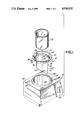
- FIG. 1 is an exploded perspective view of the ultrasonic cleaning device with a beaker holder and a beaker according to the present invention
- FIG. 2 is a perspective view of the ultrasonic cleaning device with a beaker holder of the present invention inserted therein;
- FIG. 3 is a partial sectional view taken along line 3--3 of FIG. 2;
- FIG. 4 is a partial sectional view taken on line 4--4 of FIG. 2;
- FIG. 5 is an enlarged detail of FIG. 3;
- FIG. 6 is an elevational, partially sectional, view of the beaker retained by the beaker holder which is inserted in the container of the ultrasonic cleaning device;
- FIG. 7 is a side view of the ring-shaped member of the beaker holder shown in FIG. 6 but turned by 90°.
- FIG. 1 illustrates an ultrasonic cleaning device designated at 10 and including a housing having a top wall 11 having a substantially cylindrical opening 12 which receives a can or container 14 of stainless steel material, or the like, for holding water or any other suitable liquid to which ultrasonic radiation is applied.
- a beaker holder 16 is comprised of two easily assembled and disassembled parts, including a substantially ring-shaped holding member 18 and a supporting member 20.
- a beaker 22 is inserted into the holder 16.
- the beaker is typically of glass to receive medical or dental instruments, dentures or the like, to be cleaned and also holding a cleaning solution therein.
- the ultrasonic vibrations which produce a cleaning action in the cleaning solution which fills beaker 22, are generated by a transducer and related electrical components arranged in the housing of the ultrasonic cleaning device 10.
- the transducer and other electrical components for producing the ultrasonic radiation are known and are disclosed in detail, for example in the aforementioned U.S. Pat. No. 3,937,236, the disclosure of which is incorporated herein by reference.
- the voltage is applied to the non-shown transducer by an operating knob 24 provided on the outer side wall of the housing of the cleaning device 10.
- FIG. 2 illustrates the ultrasonic cleaning device with the beaker holder inserted in the container 14 of the cleaning device.
- the beaker holder sits into the container 14 with a flange of the beaker holder seated on the upper lip of the container.
- a bottom side 30 of the beaker 22 rests on the bottom leg of the supporting part 20 of the holder.
- the ring-shaped member 18 made of plastic or similar material and includes a substantially cylindrical portion 32, which is received in an internal side wall 40 of the container 14, a frustoconical portion 42 integral with cylindrical portion 32 and merging into a radially outwardly extending flange portion 44 which rests on a lip 46 outwardly protruding from a side wall 48 of the container 14.
- the angle of frustoconical portion 42 to the central axis of the ring-shaped member is selected so that the frustoconical portion fits on the edge of the metallic container 14 thus providing a self-centering of the beaker ring in the container.
- Ring-shaped member 18 has a circumferential slot 50 which passes through the whole height of the ring-shaped member to provide the beaker ring with the flexibility. In this manner, the beaker holder can expand to adjust to various sizes of beakers being used with the ultrasonic cleaning device.
- At least three projections 52 circumferentially spaced from each other and protruding inwardly from an inner wall 54 of the cylindrical portion 32 are formed on the ring-shaped member. These projections define gripping members for holding the beaker.
- each recess includes an inverted L-shaped slot or through portion 60 which merges into a vertically extending depression 58 which constitutes the second leg of the U.
- each recess 56 is seen on the outer side of the frustoconical portion 42 as an L-shaped slot.
- This slot 60 connects in each case the external recess 62 on the cylindrical portion 32 with the depression 58 formed in the inner wall of the frustoconical portion 42 of the ring-shaped member.
- the second or supporting wire 20 of the beaker holder is made of metallic wire and includes two parallel vertical legs 70, 72 (FIGS. 1 and 6) and a base portion 74 interconnecting legs 70 and 72.
- Base portion 74 receives the bottom of beaker 22 which rests on the base 74 when the supporting wire 20 is snapped into the ring-shaped member 18.
- Each leg of the supporting wire 20 has an outwardly protruding bulge 76 near the upper end thereof and outwardly extending finger 78 at its upper free end, also shown in FIG. 4.
- two opposing outwardly extending fingers 78 of vertical legs 70, 72 are inserted through opposing slots 60.
- the fingers 78 By slightly rotating the fingers 78 in the circumferential direction along the inner wall of frustoconical portion 42 of the ring-shaped member, the fingers 78 snap respectively into two opposing depressions 58 so that the two ends of the fingers abut against the base surfaces of these depressions.
- This shifting motion is aided and limited by outer depressions 62 on which legs 70, 72 slide.
- the ends of the fingers 78 are inserted into the respective depressions 58, the vertical movement of legs 70, 72 is additionally limited by bulges 76 each resting against the wall formed by the inverted L-shaped slot 30.
- the supporting wire 20 is of metal and can be flexed.
- the slot 50 is formed on a wall of the ring-shaped member at a location about half way between the notches 56.
- the ring shaped member 18 still maintains its flexibility due to the slot 50 so that the beaker holder can still be adjusted to a beaker of a required size.
- the wire 20 will just flex outwardly or inwardly as the beaker ring adjusts to the beaker size.
- container 14 in the ultrasonic cleaning device is filled with water or any other suitable liquid and the beaker holder 16 with beaker 22 containing a cleaning solution such as a detergent, caustic, acid and the like is placed in the container. Medical or dental tools, dentures or the like to be cleaned therein, is then placed into the beaker 22.
- a cleaning solution such as a detergent, caustic, acid and the like
- Medical or dental tools, dentures or the like to be cleaned therein, is then placed into the beaker 22.
- the peripheral flange portion 44 of the ring-shaped member 18 rests on the lip 46 of container 14 while the wire support 20 firmly holds the beaker 16 within the container 14.
- the bottom wall 74 of holder 20 is preferably spaced from the bottom of container 14 by at least the amount equal to the length of a full standing ultrasonic wave. This is to prevent dampening of ultrasonic vibrations.
- the beaker is also spaced from the walls of the container and avoids dampening of the vibrations.
- the timer typically provided in the ultrasonic cleaning device is typically set for about 5 to 15 minutes depending on the degree of cleaning required or the voltage applied to the transducer of the ultrasonic cleaning device. The device is switched on by pressing the button or operating knob 24. As known, the cleaning time can be reduced by increasing the voltage applied to the transducer to thereby enhance ultrasonic vibrations.
- the holder 16 with beaker 22 therein is removed from contained 14 and placed on any available drainage tray for rinsing and then sterilization, if needed.
- beakers of various sizes can be easily placed in and held by the holder 16 inasmuch as the diameter of the inner wall of cylindrical portion 32 of the ring-shaped member 18 can be reduced or increased due to slot or cutout 50 through the ring-shaped member. It should be also noted that the distance between two vertical legs 70 and 72 of holder 20 is greater than the outer diameter of the beaker so that the beaker's outer wall is spaced from these legs which also allows for an adjustment to various size beakers.
- the holder 16 itself, is easily removable from the cleaning device for cleaning.
Abstract
Description
Claims (28)
Priority Applications (1)
| Application Number | Priority Date | Filing Date | Title |
|---|---|---|---|
| US07/312,033 US4930532A (en) | 1989-02-17 | 1989-02-17 | Beaker holder for use with ultrasonic cleaning device |
Applications Claiming Priority (1)
| Application Number | Priority Date | Filing Date | Title |
|---|---|---|---|
| US07/312,033 US4930532A (en) | 1989-02-17 | 1989-02-17 | Beaker holder for use with ultrasonic cleaning device |
Publications (1)
| Publication Number | Publication Date |
|---|---|
| US4930532A true US4930532A (en) | 1990-06-05 |
Family
ID=23209587
Family Applications (1)
| Application Number | Title | Priority Date | Filing Date |
|---|---|---|---|
| US07/312,033 Expired - Fee Related US4930532A (en) | 1989-02-17 | 1989-02-17 | Beaker holder for use with ultrasonic cleaning device |
Country Status (1)
| Country | Link |
|---|---|
| US (1) | US4930532A (en) |
Cited By (24)
| Publication number | Priority date | Publication date | Assignee | Title |
|---|---|---|---|---|
| US5076305A (en) * | 1990-08-13 | 1991-12-31 | Kevin T. Williams | Apparatus for cleaning by rapid vibration |
| US5403555A (en) * | 1992-10-22 | 1995-04-04 | Kaltenbach & Voigt Gmbh & Co. | Device for cleaning and/or disinfecting and/or maintaining medical or dental instruments |
| US6030463A (en) * | 1998-07-24 | 2000-02-29 | Rusczyk; Lester Lee | System and method for ultrasonic cleaning and degreasing |
| WO2001046714A1 (en) * | 1999-12-10 | 2001-06-28 | Misonix Incorporated | Ultrasonic horn assembly |
| US6578659B2 (en) | 2000-12-01 | 2003-06-17 | Misonix Incorporated | Ultrasonic horn assembly |
| US20030223305A1 (en) * | 2002-06-03 | 2003-12-04 | Halsall Richard W. | Method for continuous internal agitation of fluid within hot water heaters or other fluid containing vessels |
| US20040079580A1 (en) * | 2002-10-28 | 2004-04-29 | Manna Ronald R. | Ultrasonic horn |
| WO2005025730A1 (en) * | 2003-09-10 | 2005-03-24 | Burr Ronald F | Acoustic fluidized bed |
| US20060241470A1 (en) * | 2005-03-23 | 2006-10-26 | Misonix Incorporated | Ultrasonic wound debrider probe and method of use |
| US20080031094A1 (en) * | 2006-08-01 | 2008-02-07 | Covaris, Inc. | Methods and apparatus for treating samples with acoustic energy |
| US20080058775A1 (en) * | 2006-08-29 | 2008-03-06 | Darian Alexander L | Ultrasonic debrider probe and method of use |
| US20090317884A1 (en) * | 2008-06-24 | 2009-12-24 | Covaris, Inc. | Method and apparatus for treatment enhancement in acoustic processing of samples |
| US20100008178A1 (en) * | 2008-07-14 | 2010-01-14 | Dale Fahrion | Acoustic Beverage Mixer |
| EP2193879A1 (en) * | 2008-12-05 | 2010-06-09 | Mikron Agie Charmilles AG | Tool cleaning |
| US20120015419A1 (en) * | 2008-06-24 | 2012-01-19 | Covaris, Inc. | Method and apparatus for headspace control in acoustic processing of samples |
| USD739038S1 (en) * | 2014-03-02 | 2015-09-15 | Helen Of Troy Limited | Beaker |
| CN106687797A (en) * | 2014-09-26 | 2017-05-17 | 西门子医疗保健诊断公司 | Phase-modulated standing wave mixing apparatus and methods |
| USD920504S1 (en) | 2019-07-01 | 2021-05-25 | Medline Industries, Inc. | Valve |
| USD925033S1 (en) | 2019-07-01 | 2021-07-13 | Medline Industries, Inc. | Valve clip |
| US11110036B2 (en) | 2019-07-01 | 2021-09-07 | Medline Industries, Inc. | Feeding set and enteral feeding pump assembly |
| US11160920B2 (en) * | 2019-01-24 | 2021-11-02 | Medline Industries, Inc. | Feeding syringe holder |
| US11344480B2 (en) | 2018-07-26 | 2022-05-31 | Medline Industries, Lp | Enteral fluid delivery system |
| USD971530S1 (en) * | 2019-03-06 | 2022-11-29 | Cleanbox Technology, Inc. | Cleaning device |
| US11910815B2 (en) * | 2019-12-02 | 2024-02-27 | Pepsico, Inc. | Device and method for nucleation of a supercooled beverage |
Citations (7)
| Publication number | Priority date | Publication date | Assignee | Title |
|---|---|---|---|---|
| US3544073A (en) * | 1967-09-08 | 1970-12-01 | Albert G Bodine | Elastomer resonator for orbiting mass oscillator |
| US3709429A (en) * | 1970-10-19 | 1973-01-09 | Kenzie D Mc | Centrifuges |
| US3807704A (en) * | 1972-11-13 | 1974-04-30 | Phillips Petroleum Co | Dispersing and mixing apparatus |
| US3842981A (en) * | 1973-05-17 | 1974-10-22 | T Lambert | Apparatus for removably holding a liquid beverage container |
| US3937236A (en) * | 1974-10-07 | 1976-02-10 | Mdt Chemical Company | Ultrasonic cleaning device |
| GB1456140A (en) * | 1973-09-24 | 1976-11-17 | Sonics International Corp | Ultrasonic denture bath assembly and method |
| US4442852A (en) * | 1982-07-30 | 1984-04-17 | Lord C Dennis | Ultrasonic cleaner apparatus |
-
1989
- 1989-02-17 US US07/312,033 patent/US4930532A/en not_active Expired - Fee Related
Patent Citations (7)
| Publication number | Priority date | Publication date | Assignee | Title |
|---|---|---|---|---|
| US3544073A (en) * | 1967-09-08 | 1970-12-01 | Albert G Bodine | Elastomer resonator for orbiting mass oscillator |
| US3709429A (en) * | 1970-10-19 | 1973-01-09 | Kenzie D Mc | Centrifuges |
| US3807704A (en) * | 1972-11-13 | 1974-04-30 | Phillips Petroleum Co | Dispersing and mixing apparatus |
| US3842981A (en) * | 1973-05-17 | 1974-10-22 | T Lambert | Apparatus for removably holding a liquid beverage container |
| GB1456140A (en) * | 1973-09-24 | 1976-11-17 | Sonics International Corp | Ultrasonic denture bath assembly and method |
| US3937236A (en) * | 1974-10-07 | 1976-02-10 | Mdt Chemical Company | Ultrasonic cleaning device |
| US4442852A (en) * | 1982-07-30 | 1984-04-17 | Lord C Dennis | Ultrasonic cleaner apparatus |
Cited By (38)
| Publication number | Priority date | Publication date | Assignee | Title |
|---|---|---|---|---|
| US5076305A (en) * | 1990-08-13 | 1991-12-31 | Kevin T. Williams | Apparatus for cleaning by rapid vibration |
| US5403555A (en) * | 1992-10-22 | 1995-04-04 | Kaltenbach & Voigt Gmbh & Co. | Device for cleaning and/or disinfecting and/or maintaining medical or dental instruments |
| US6030463A (en) * | 1998-07-24 | 2000-02-29 | Rusczyk; Lester Lee | System and method for ultrasonic cleaning and degreasing |
| WO2001046714A1 (en) * | 1999-12-10 | 2001-06-28 | Misonix Incorporated | Ultrasonic horn assembly |
| US6578659B2 (en) | 2000-12-01 | 2003-06-17 | Misonix Incorporated | Ultrasonic horn assembly |
| US20030223305A1 (en) * | 2002-06-03 | 2003-12-04 | Halsall Richard W. | Method for continuous internal agitation of fluid within hot water heaters or other fluid containing vessels |
| US6736535B2 (en) * | 2002-06-03 | 2004-05-18 | Richard W. Halsall | Method for continuous internal agitation of fluid within hot water heaters or other fluid containing vessels |
| US7004282B2 (en) | 2002-10-28 | 2006-02-28 | Misonix, Incorporated | Ultrasonic horn |
| US20040079580A1 (en) * | 2002-10-28 | 2004-04-29 | Manna Ronald R. | Ultrasonic horn |
| WO2005025730A1 (en) * | 2003-09-10 | 2005-03-24 | Burr Ronald F | Acoustic fluidized bed |
| US20060152998A1 (en) * | 2003-09-10 | 2006-07-13 | Burr Ronald F | Acoustic fluidized bed |
| US20060241470A1 (en) * | 2005-03-23 | 2006-10-26 | Misonix Incorporated | Ultrasonic wound debrider probe and method of use |
| US7931611B2 (en) | 2005-03-23 | 2011-04-26 | Misonix, Incorporated | Ultrasonic wound debrider probe and method of use |
| US20080031094A1 (en) * | 2006-08-01 | 2008-02-07 | Covaris, Inc. | Methods and apparatus for treating samples with acoustic energy |
| US8353619B2 (en) * | 2006-08-01 | 2013-01-15 | Covaris, Inc. | Methods and apparatus for treating samples with acoustic energy |
| US20080058775A1 (en) * | 2006-08-29 | 2008-03-06 | Darian Alexander L | Ultrasonic debrider probe and method of use |
| US20120015419A1 (en) * | 2008-06-24 | 2012-01-19 | Covaris, Inc. | Method and apparatus for headspace control in acoustic processing of samples |
| US20090317884A1 (en) * | 2008-06-24 | 2009-12-24 | Covaris, Inc. | Method and apparatus for treatment enhancement in acoustic processing of samples |
| US8999704B2 (en) * | 2008-06-24 | 2015-04-07 | Covaris, Inc. | Method and apparatus for headspace control in acoustic processing of samples |
| US9267867B2 (en) * | 2008-06-24 | 2016-02-23 | Covaris, Inc. | Method and apparatus for treatment enhancement in acoustic processing of samples |
| US9790485B2 (en) | 2008-06-24 | 2017-10-17 | Covaris, Inc. | Method and apparatus for headspace control in acoustic processing of samples |
| US20100008178A1 (en) * | 2008-07-14 | 2010-01-14 | Dale Fahrion | Acoustic Beverage Mixer |
| EP2193879A1 (en) * | 2008-12-05 | 2010-06-09 | Mikron Agie Charmilles AG | Tool cleaning |
| USD739038S1 (en) * | 2014-03-02 | 2015-09-15 | Helen Of Troy Limited | Beaker |
| CN106687797A (en) * | 2014-09-26 | 2017-05-17 | 西门子医疗保健诊断公司 | Phase-modulated standing wave mixing apparatus and methods |
| US10737228B2 (en) * | 2014-09-26 | 2020-08-11 | Siemens Healthcare Diagnostics Inc | Phase-modulated standing wave mixing apparatus and methods |
| CN106687797B (en) * | 2014-09-26 | 2020-11-10 | 西门子医疗保健诊断公司 | Phase-modulated standing wave mixing device and method |
| US11344480B2 (en) | 2018-07-26 | 2022-05-31 | Medline Industries, Lp | Enteral fluid delivery system |
| US11160920B2 (en) * | 2019-01-24 | 2021-11-02 | Medline Industries, Inc. | Feeding syringe holder |
| US20220016335A1 (en) * | 2019-01-24 | 2022-01-20 | Medline Industries, Lp | Feeding syringe holder |
| US11612685B2 (en) * | 2019-01-24 | 2023-03-28 | Medline Industries, Lp | Feeding syringe holder |
| USD971530S1 (en) * | 2019-03-06 | 2022-11-29 | Cleanbox Technology, Inc. | Cleaning device |
| USD925033S1 (en) | 2019-07-01 | 2021-07-13 | Medline Industries, Inc. | Valve clip |
| US11110036B2 (en) | 2019-07-01 | 2021-09-07 | Medline Industries, Inc. | Feeding set and enteral feeding pump assembly |
| USD920504S1 (en) | 2019-07-01 | 2021-05-25 | Medline Industries, Inc. | Valve |
| USD972721S1 (en) | 2019-07-01 | 2022-12-13 | Medline Industries, Lp | Valve |
| USD1010113S1 (en) | 2019-07-01 | 2024-01-02 | Medline Industries, Lp | Valve |
| US11910815B2 (en) * | 2019-12-02 | 2024-02-27 | Pepsico, Inc. | Device and method for nucleation of a supercooled beverage |
Similar Documents
| Publication | Publication Date | Title |
|---|---|---|
| US4930532A (en) | Beaker holder for use with ultrasonic cleaning device | |
| US3937236A (en) | Ultrasonic cleaning device | |
| KR101629401B1 (en) | Frying pan holder | |
| EP0062357A2 (en) | An apparatus for treating the surface of instruments | |
| US5433930A (en) | Screen basket for sterilizating containers | |
| US7871582B2 (en) | Medical instrument container system | |
| US4870982A (en) | Ultrasonic cleaning apparatus for household use | |
| US5422067A (en) | Instrument cassette and method for using the same | |
| JPH02157189A (en) | Epitaxial growth reactor | |
| JP2004503224A (en) | Animal food container | |
| RU2672679C1 (en) | Insertion for kitchen device | |
| US6253931B1 (en) | Oral hygiene product storage system | |
| WO2007046751A1 (en) | Apparatus for feeding-bottles | |
| CN215312085U (en) | Medical fixed bolster for shaking appearance | |
| JP2020062221A (en) | Instrument washing holder | |
| SU1423108A1 (en) | Field table-ware | |
| EP0217798A1 (en) | A holder and a casing of a household implement, especially a can opener. | |
| US528163A (en) | Dental mirror | |
| CN213156185U (en) | Medical clamp | |
| US11040822B1 (en) | Device for holding a racking cane | |
| JP2540619Y2 (en) | Rack for lens | |
| KR200260530Y1 (en) | cooker supporter | |
| KR200180629Y1 (en) | Filth box of tables for dentistry | |
| JP3198561U (en) | Container fixture | |
| EP0766971A1 (en) | A device for holding dental handpieces in the apparatus where they are disinfected and sterilized |
Legal Events
| Date | Code | Title | Description |
|---|---|---|---|
| AS | Assignment |
Owner name: IPCO CORPORATION, NEW YORK Free format text: ASSIGNMENT OF ASSIGNORS INTEREST.;ASSIGNOR:MAYER, STANLEY E.;REEL/FRAME:005045/0663 Effective date: 19890207 |
|
| AS | Assignment |
Owner name: G H ACQUISITION CORP., A CORP. OF DE, NEW YORK Free format text: ASSIGNMENT OF ASSIGNORS INTEREST.;ASSIGNOR:IPCO CORPORATION;REEL/FRAME:005604/0279 Effective date: 19900601 Owner name: WHALEDENT INC. Free format text: CHANGE OF NAME;ASSIGNOR:G H ACQUISITION CORP.;REEL/FRAME:005604/0299 Effective date: 19900601 Owner name: COLTENE/WHALEDENT INC. Free format text: CHANGE OF NAME;ASSIGNOR:WHALENDENT INC.;REEL/FRAME:005604/0290 Effective date: 19901002 |
|
| FEPP | Fee payment procedure |
Free format text: PAYOR NUMBER ASSIGNED (ORIGINAL EVENT CODE: ASPN); ENTITY STATUS OF PATENT OWNER: LARGE ENTITY |
|
| REMI | Maintenance fee reminder mailed | ||
| LAPS | Lapse for failure to pay maintenance fees | ||
| FP | Lapsed due to failure to pay maintenance fee |
Effective date: 19940608 |
|
| STCH | Information on status: patent discontinuation |
Free format text: PATENT EXPIRED DUE TO NONPAYMENT OF MAINTENANCE FEES UNDER 37 CFR 1.362 |