US4932905A - Electrical connector clip - Google Patents
Electrical connector clip Download PDFInfo
- Publication number
- US4932905A US4932905A US07/412,782 US41278289A US4932905A US 4932905 A US4932905 A US 4932905A US 41278289 A US41278289 A US 41278289A US 4932905 A US4932905 A US 4932905A
- Authority
- US
- United States
- Prior art keywords
- clip
- portions
- jaw
- pivot
- body portion
- Prior art date
- Legal status (The legal status is an assumption and is not a legal conclusion. Google has not performed a legal analysis and makes no representation as to the accuracy of the status listed.)
- Expired - Lifetime
Links
Images
Classifications
-
- H—ELECTRICITY
- H01—ELECTRIC ELEMENTS
- H01R—ELECTRICALLY-CONDUCTIVE CONNECTIONS; STRUCTURAL ASSOCIATIONS OF A PLURALITY OF MUTUALLY-INSULATED ELECTRICAL CONNECTING ELEMENTS; COUPLING DEVICES; CURRENT COLLECTORS
- H01R11/00—Individual connecting elements providing two or more spaced connecting locations for conductive members which are, or may be, thereby interconnected, e.g. end pieces for wires or cables supported by the wire or cable and having means for facilitating electrical connection to some other wire, terminal, or conductive member, blocks of binding posts
- H01R11/11—End pieces or tapping pieces for wires, supported by the wire and for facilitating electrical connection to some other wire, terminal or conductive member
- H01R11/22—End pieces terminating in a spring clip
- H01R11/24—End pieces terminating in a spring clip with gripping jaws, e.g. crocodile clip
Definitions
- the present invention relates to an electrical connector clip for making a permanent or a temporary electrical connection e.g. for use as a battery terminal connector or for laboratory work.
- Electrical connector clips generally available at present are of the type disclosed in U.S. Pat. Nos. 4781629 and 4685760. These clips are made of metal, so that insulating sleeves must be fitted to allow the clips to be handled. These clips comprise two complementary body portions which are pivoted together at or near the mid-point to provide connecting jaws at one side of the pivot and handle portions at the other side of the pivot, with a spring arranged to bias the handle portions apart, and hence urge the jaws together. To open the jaws, the handle portions are pressed together against the bias of the spring.
- This type of construction has two major drawbacks: firstly, the positioning of the spring places considerable stress on the pivot, and makes the clip comparatively hard to operate, because spring pressure is applied to the jaws only indirectly. Secondly, most of the wear on the clip is on the jaws, but since these are formed integrally with the rest of the clip, the whole clip must be replaced when the jaws wear out.
- An object of the present invention is the provision of a clip which overcomes the above-described disadvantages.
- the present invention provides an electrical connector clip comprising: two insulating body portions secured together about a pivot so as to provide handle portions at one side of the pivot and gripping portions at the other side of the pivot, said gripping portions being biassed towards each other by an electrically conducting spring mounted around the pivot and extending along said gripping portions; at least the outer end of each said gripping portion being provided with a replaceable jaw made of electrically conducting material, each said jaw being dimensioned and arranged to be in electrical contact both with said spring and with any article gripped between said gripping portions.
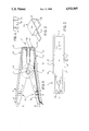
- FIG. 1 is a longitudinal section through a clip of the present invention
- FIG. 2 is a plan view of one-half of the body of the clip of FIG. 1;
- FIG. 3 is an isometric view of one of the replaceable jaws of the clip of FIG. 1;
- FIG. 4 is a side view of the pivot pin.
- a clip 2 comprises two identical body portions 3, 4, which are pivoted together by a pivot pin 5.
- Each body portion 3, 4, is made of a rigid insulating material (e.g. a rigid plastics material) and comprises a rectangular base 6 formed with a peripheral rim which forms end walls 7, 8, and side walls 9, 10, all substantially perpendicular to the plane of the base.
- An aperture 11 is formed through the base 6 adjacent the rear end wall 8; one end of said aperture 11 opens into an aperture 11aformed through said wall 8.
- a second aperture 12 is formed through the base 6 between the front end wall 7 and the point at which the body portions are pivoted together.
- Two circular bosses 13, 14 are formed one on each side wall 9, 10.
- a large boss 13 is formed, with the inner face of the boss contiguous with the outer face of the wall 9, and a part-circular socket 15 is formed in said wall 9, concentric with said boss 13.
- a small boss 14 is formed, in the plane of the wall 10 and opposite the boss 13 so that the centres of said bosses are coaxial.
- the bosses 13, 14, lie in planes parallel to each other and to the plane of the side walls 9 and 10.
- a hole 16, 17, is formed through the centre of each boss 13, 14.
- the bosses 13, 14 on each body portion are arranged with the boss 13 of each body portion lying on the outside of, but parallel to, the boss 14 of the other body portion, and the boss 14 of each portion lying in the socket 15 of the other portion.
- the pivot pin 5 extends through the aligned holes 16, 17, and is secured in known manner, fastening the two body portions pivotally together.
- the pivot pin 5 may be of any suitable known type, but preferably is as shown in FIG. 4, and comprises a generally cylindrical pin 33 formed with two spaced pairs of projections 34 on the outer surface thereof, and two cut-outs 35 through the pin, each centered on one of the pairs of projections 34. Each pair of projections 34 is positioned so as to lie against the inner wall of the corresponding boss 14.
- the cut-outs 35 allow the pin 5 to compress sufficiently to allow the pin to be push-fitted through the holes 16, 17, but once in place the pin 5 springs back into its original shape, and the pairs of projections 34 prevent the pin from sliding sideways out of the holes 16, 17.
- the bosses 13, 14 are formed about 5/8 along the length of the respective body portions, forming a clip with a relatively long handle 20 and a relatively short gripping end 21. However, it will be appreciated that these proportions may be varied as required, for different applications.
- a spring 22 is mounted on the pin 5, and is arranged to bias the gripping end of the clip towards the closed position shown in FIG. 1.
- the spring 22 comprises a coil spring mounted coaxially upon the pin 5, the spring 22 being formed with elongated ends 23, 24 which extend towards the front end of the clip and are bent through 90° to form a foot which lies against, or adjacent, the respective front end walls 7.
- One end 23 extends from the spring 22 diagonally across the front end of the clip to one end wall 7, and the other end extends from the spring 22 diagonally across the front end of the clip to the other end wall 7.
- the spring 22 tends to urge the halves of the front end of the clip together; pressure in the direction of arrows A on the handle end of the clip will tend to overcome the spring pressure and force the halves of the gripping end of the clip apart.
- a metal replaceable jaw 25 is fitted over each wall 7 of the clip.
- Each jaw 25 is as shown in FIG. 3 and comprises a generally U-cross-section portion, dimensioned to fit over the end wall 7 of each body portion with a first part 26 lying on the outer surface of the base 6, a second part 27 lying over the outer surface of the front end wall 7, and a third part 28 parallel to said first part, lying on the interior of the clip and serrated to form two parallel gripping surfaces.
- the serrations of the opposed parts 28 are complementary, and the jaws may be proportioned so that the serrations mesh with each other when the jaws are closed, or may be proportioned so that the gripping surfaces on one jaw are staggered relative to the gripping surfaces on the other jaw, thus giving the jaws four separate areas of electrical contact with an article gripped between the jaws.
- An elongated part 29 is formed integrally with the first part 26, and extends through the aperture 12 in the base 6, terminating in the interior of the clip.
- a wire 30 terminating in a connector of known type e.g. a spade connector
- the wire 30 is led into the interior of the clip through apertures 11/11a, and is gripped either between the sides of an apertured boss 31 formed integrally with the interior wall of the base 6, or between the exterior of said boss 31 and projections 32 formed on the adjacent side walls 9, 10, depending upon the diameter of the wire.
- the spring 22 is made of metal, and the ends 23, 24, of the spring contact the parts 28 of the jaws, the spring provides an electrical connection between the two jaws, ensuring an even electrical connection between the wire 30 and any object gripped between the jaws.
- the jaws 25 may be quickly and easily replaced when they become worn, and different styles of jaws may be substituted as needed for particular applications. It is also envisaged that the jaws may be designed with the part 28 pivoted to the remainder of the jaw, to allow improved electrical contact between the jaws and articles of rectangular cross-section.
- the jaws 25 are positively urged together by the spring, rather than being urged together by the spring urging the handle portions apart. This minimises the force required to open the clip, and also minimises the forces on the pivot pin 5.
- each body portion could be made double-ended i.e. with the apertures 11 and 12 formed at each end of the clip, so that the same body and jaw components could be assembled to form a clip with a longer or shorter gripping end, simply by using a longer or shorter spring on the longer or shorter side of the body portions, as appropriate.
- the clip body portions are at all times fully insulated, and may be manufactured in a wide range of colours, so that different electrical connections can be easily identified.
- the body portions are identical, so tooling costs are minimised. However, if tooling costs are not a major consideration, the body portions need not be identical.
- the jaws 25 may be constructed so as to lie entirely within the corresponding body portion.
Abstract
Description
Claims (12)
Applications Claiming Priority (2)
| Application Number | Priority Date | Filing Date | Title |
|---|---|---|---|
| NZ226409 | 1988-09-30 | ||
| NZ226409A NZ226409A (en) | 1988-09-30 | 1988-09-30 | Electrical connector clip: replaceable jaws |
Publications (1)
| Publication Number | Publication Date |
|---|---|
| US4932905A true US4932905A (en) | 1990-06-12 |
Family
ID=19922610
Family Applications (1)
| Application Number | Title | Priority Date | Filing Date |
|---|---|---|---|
| US07/412,782 Expired - Lifetime US4932905A (en) | 1988-09-30 | 1989-09-26 | Electrical connector clip |
Country Status (5)
| Country | Link |
|---|---|
| US (1) | US4932905A (en) |
| AU (1) | AU617873B2 (en) |
| CA (1) | CA1308455C (en) |
| GB (1) | GB2227615B (en) |
| NZ (1) | NZ226409A (en) |
Cited By (60)
| Publication number | Priority date | Publication date | Assignee | Title |
|---|---|---|---|---|
| US5123861A (en) * | 1990-07-06 | 1992-06-23 | Verge Cyril | Battery booster insulating boot |
| US5613884A (en) * | 1995-06-06 | 1997-03-25 | Snap-On Technologies, Inc. | Position latch device |
| US7598699B2 (en) * | 2004-02-20 | 2009-10-06 | Midtronics, Inc. | Replaceable clamp for electronic battery tester |
| US7656162B2 (en) | 1996-07-29 | 2010-02-02 | Midtronics Inc. | Electronic battery tester with vehicle type input |
| US7688074B2 (en) | 1997-11-03 | 2010-03-30 | Midtronics, Inc. | Energy management system for automotive vehicle |
| US7705602B2 (en) | 1997-11-03 | 2010-04-27 | Midtronics, Inc. | Automotive vehicle electrical system diagnostic device |
| US7706991B2 (en) | 1996-07-29 | 2010-04-27 | Midtronics, Inc. | Alternator tester |
| US7710119B2 (en) | 2004-12-09 | 2010-05-04 | Midtronics, Inc. | Battery tester that calculates its own reference values |
| US7728597B2 (en) | 2000-03-27 | 2010-06-01 | Midtronics, Inc. | Electronic battery tester with databus |
| US7772850B2 (en) | 2004-07-12 | 2010-08-10 | Midtronics, Inc. | Wireless battery tester with information encryption means |
| US7777612B2 (en) | 2004-04-13 | 2010-08-17 | Midtronics, Inc. | Theft prevention device for automotive vehicle service centers |
| US7791348B2 (en) | 2007-02-27 | 2010-09-07 | Midtronics, Inc. | Battery tester with promotion feature to promote use of the battery tester by providing the user with codes having redeemable value |
| US7808375B2 (en) | 2007-04-16 | 2010-10-05 | Midtronics, Inc. | Battery run down indicator |
| US7977914B2 (en) | 2003-10-08 | 2011-07-12 | Midtronics, Inc. | Battery maintenance tool with probe light |
| US7999505B2 (en) | 1997-11-03 | 2011-08-16 | Midtronics, Inc. | In-vehicle battery monitor |
| US8164343B2 (en) | 2003-09-05 | 2012-04-24 | Midtronics, Inc. | Method and apparatus for measuring a parameter of a vehicle electrical system |
| US8198900B2 (en) | 1996-07-29 | 2012-06-12 | Midtronics, Inc. | Automotive battery charging system tester |
| US8203345B2 (en) | 2007-12-06 | 2012-06-19 | Midtronics, Inc. | Storage battery and battery tester |
| US8237448B2 (en) | 2000-03-27 | 2012-08-07 | Midtronics, Inc. | Battery testers with secondary functionality |
| US8306690B2 (en) | 2007-07-17 | 2012-11-06 | Midtronics, Inc. | Battery tester for electric vehicle |
| US8344685B2 (en) | 2004-08-20 | 2013-01-01 | Midtronics, Inc. | System for automatically gathering battery information |
| US8436619B2 (en) | 2004-08-20 | 2013-05-07 | Midtronics, Inc. | Integrated tag reader and environment sensor |
| US8442877B2 (en) | 2004-08-20 | 2013-05-14 | Midtronics, Inc. | Simplification of inventory management |
| US8513949B2 (en) | 2000-03-27 | 2013-08-20 | Midtronics, Inc. | Electronic battery tester or charger with databus connection |
| US8674711B2 (en) | 2003-09-05 | 2014-03-18 | Midtronics, Inc. | Method and apparatus for measuring a parameter of a vehicle electrical system |
| US8738309B2 (en) | 2010-09-30 | 2014-05-27 | Midtronics, Inc. | Battery pack maintenance for electric vehicles |
| US8872517B2 (en) | 1996-07-29 | 2014-10-28 | Midtronics, Inc. | Electronic battery tester with battery age input |
| US8958998B2 (en) | 1997-11-03 | 2015-02-17 | Midtronics, Inc. | Electronic battery tester with network communication |
| US9018958B2 (en) | 2003-09-05 | 2015-04-28 | Midtronics, Inc. | Method and apparatus for measuring a parameter of a vehicle electrical system |
| US9201120B2 (en) | 2010-08-12 | 2015-12-01 | Midtronics, Inc. | Electronic battery tester for testing storage battery |
| US9229062B2 (en) | 2010-05-27 | 2016-01-05 | Midtronics, Inc. | Electronic storage battery diagnostic system |
| US9244100B2 (en) | 2013-03-15 | 2016-01-26 | Midtronics, Inc. | Current clamp with jaw closure detection |
| US9255955B2 (en) | 2003-09-05 | 2016-02-09 | Midtronics, Inc. | Method and apparatus for measuring a parameter of a vehicle electrical system |
| US9274157B2 (en) | 2007-07-17 | 2016-03-01 | Midtronics, Inc. | Battery tester for electric vehicle |
| US9312575B2 (en) | 2013-05-16 | 2016-04-12 | Midtronics, Inc. | Battery testing system and method |
| US9419311B2 (en) | 2010-06-18 | 2016-08-16 | Midtronics, Inc. | Battery maintenance device with thermal buffer |
| US9425487B2 (en) | 2010-03-03 | 2016-08-23 | Midtronics, Inc. | Monitor for front terminal batteries |
| US9496720B2 (en) | 2004-08-20 | 2016-11-15 | Midtronics, Inc. | System for automatically gathering battery information |
| US9588185B2 (en) | 2010-02-25 | 2017-03-07 | Keith S. Champlin | Method and apparatus for detecting cell deterioration in an electrochemical cell or battery |
| US9851411B2 (en) | 2012-06-28 | 2017-12-26 | Keith S. Champlin | Suppressing HF cable oscillations during dynamic measurements of cells and batteries |
| US9923289B2 (en) | 2014-01-16 | 2018-03-20 | Midtronics, Inc. | Battery clamp with endoskeleton design |
| US9966676B2 (en) | 2015-09-28 | 2018-05-08 | Midtronics, Inc. | Kelvin connector adapter for storage battery |
| US10046649B2 (en) | 2012-06-28 | 2018-08-14 | Midtronics, Inc. | Hybrid and electric vehicle battery pack maintenance device |
| US10222397B2 (en) | 2014-09-26 | 2019-03-05 | Midtronics, Inc. | Cable connector for electronic battery tester |
| US10317468B2 (en) | 2015-01-26 | 2019-06-11 | Midtronics, Inc. | Alternator tester |
| US10429449B2 (en) | 2011-11-10 | 2019-10-01 | Midtronics, Inc. | Battery pack tester |
| US10473555B2 (en) | 2014-07-14 | 2019-11-12 | Midtronics, Inc. | Automotive maintenance system |
| US10608353B2 (en) | 2016-06-28 | 2020-03-31 | Midtronics, Inc. | Battery clamp |
| US10843574B2 (en) | 2013-12-12 | 2020-11-24 | Midtronics, Inc. | Calibration and programming of in-vehicle battery sensors |
| US11054480B2 (en) | 2016-10-25 | 2021-07-06 | Midtronics, Inc. | Electrical load for electronic battery tester and electronic battery tester including such electrical load |
| USD943103S1 (en) * | 2020-04-22 | 2022-02-08 | Barry Alan Snider, Sr. | Kneepad supports |
| US11325479B2 (en) | 2012-06-28 | 2022-05-10 | Midtronics, Inc. | Hybrid and electric vehicle battery maintenance device |
| US11474153B2 (en) | 2019-11-12 | 2022-10-18 | Midtronics, Inc. | Battery pack maintenance system |
| US11486930B2 (en) | 2020-01-23 | 2022-11-01 | Midtronics, Inc. | Electronic battery tester with battery clamp storage holsters |
| US11513160B2 (en) | 2018-11-29 | 2022-11-29 | Midtronics, Inc. | Vehicle battery maintenance device |
| US11545839B2 (en) | 2019-11-05 | 2023-01-03 | Midtronics, Inc. | System for charging a series of connected batteries |
| US11566972B2 (en) | 2019-07-31 | 2023-01-31 | Midtronics, Inc. | Tire tread gauge using visual indicator |
| US11650259B2 (en) | 2010-06-03 | 2023-05-16 | Midtronics, Inc. | Battery pack maintenance for electric vehicle |
| US11668779B2 (en) | 2019-11-11 | 2023-06-06 | Midtronics, Inc. | Hybrid and electric vehicle battery pack maintenance device |
| US11740294B2 (en) | 2010-06-03 | 2023-08-29 | Midtronics, Inc. | High use battery pack maintenance |
Families Citing this family (1)
| Publication number | Priority date | Publication date | Assignee | Title |
|---|---|---|---|---|
| GB2551959A (en) * | 2016-06-08 | 2018-01-10 | Lyle Purton Alan | An electrical clamp |
Citations (3)
| Publication number | Priority date | Publication date | Assignee | Title |
|---|---|---|---|---|
| US2762028A (en) * | 1955-05-16 | 1956-09-04 | Mueller Electric Company | Electrical connection clip |
| US3644877A (en) * | 1970-07-10 | 1972-02-22 | Carbonneau Ind Inc | Test clip for electrical conductor |
| US3737832A (en) * | 1971-09-27 | 1973-06-05 | G Anderson | Electrical clamp |
Family Cites Families (4)
| Publication number | Priority date | Publication date | Assignee | Title |
|---|---|---|---|---|
| BE521282A (en) * | 1952-07-11 | |||
| GB1151833A (en) * | 1968-01-22 | 1969-05-14 | Cossor Ltd A C | A Clip for Facilitating the Testing of Micro-Electronic Packages. |
| US3625590A (en) * | 1969-11-05 | 1971-12-07 | Ibm | Optical circulator and energy converter |
| US3641473A (en) * | 1970-05-28 | 1972-02-08 | Thomas J Attaway | Vehicle-grounding clamp |
-
1988
- 1988-09-30 NZ NZ226409A patent/NZ226409A/en unknown
-
1989
- 1989-09-26 US US07/412,782 patent/US4932905A/en not_active Expired - Lifetime
- 1989-09-27 CA CA000613574A patent/CA1308455C/en not_active Expired - Lifetime
- 1989-09-29 AU AU42459/89A patent/AU617873B2/en not_active Expired
- 1989-09-29 GB GB8922006A patent/GB2227615B/en not_active Expired - Lifetime
Patent Citations (3)
| Publication number | Priority date | Publication date | Assignee | Title |
|---|---|---|---|---|
| US2762028A (en) * | 1955-05-16 | 1956-09-04 | Mueller Electric Company | Electrical connection clip |
| US3644877A (en) * | 1970-07-10 | 1972-02-22 | Carbonneau Ind Inc | Test clip for electrical conductor |
| US3737832A (en) * | 1971-09-27 | 1973-06-05 | G Anderson | Electrical clamp |
Cited By (73)
| Publication number | Priority date | Publication date | Assignee | Title |
|---|---|---|---|---|
| US5123861A (en) * | 1990-07-06 | 1992-06-23 | Verge Cyril | Battery booster insulating boot |
| US5613884A (en) * | 1995-06-06 | 1997-03-25 | Snap-On Technologies, Inc. | Position latch device |
| US7940052B2 (en) | 1996-07-29 | 2011-05-10 | Midtronics, Inc. | Electronic battery test based upon battery requirements |
| US7706991B2 (en) | 1996-07-29 | 2010-04-27 | Midtronics, Inc. | Alternator tester |
| US8198900B2 (en) | 1996-07-29 | 2012-06-12 | Midtronics, Inc. | Automotive battery charging system tester |
| US8872517B2 (en) | 1996-07-29 | 2014-10-28 | Midtronics, Inc. | Electronic battery tester with battery age input |
| US7656162B2 (en) | 1996-07-29 | 2010-02-02 | Midtronics Inc. | Electronic battery tester with vehicle type input |
| US8674654B2 (en) | 1997-11-03 | 2014-03-18 | Midtronics, Inc. | In-vehicle battery monitor |
| US7688074B2 (en) | 1997-11-03 | 2010-03-30 | Midtronics, Inc. | Energy management system for automotive vehicle |
| US7705602B2 (en) | 1997-11-03 | 2010-04-27 | Midtronics, Inc. | Automotive vehicle electrical system diagnostic device |
| US8493022B2 (en) | 1997-11-03 | 2013-07-23 | Midtronics, Inc. | Automotive vehicle electrical system diagnostic device |
| US8958998B2 (en) | 1997-11-03 | 2015-02-17 | Midtronics, Inc. | Electronic battery tester with network communication |
| US7999505B2 (en) | 1997-11-03 | 2011-08-16 | Midtronics, Inc. | In-vehicle battery monitor |
| US8754653B2 (en) | 1999-11-01 | 2014-06-17 | Midtronics, Inc. | Electronic battery tester |
| US8872516B2 (en) | 2000-03-27 | 2014-10-28 | Midtronics, Inc. | Electronic battery tester mounted in a vehicle |
| US8237448B2 (en) | 2000-03-27 | 2012-08-07 | Midtronics, Inc. | Battery testers with secondary functionality |
| US8513949B2 (en) | 2000-03-27 | 2013-08-20 | Midtronics, Inc. | Electronic battery tester or charger with databus connection |
| US7924015B2 (en) | 2000-03-27 | 2011-04-12 | Midtronics, Inc. | Automotive vehicle battery test system |
| US7728597B2 (en) | 2000-03-27 | 2010-06-01 | Midtronics, Inc. | Electronic battery tester with databus |
| US9052366B2 (en) | 2000-03-27 | 2015-06-09 | Midtronics, Inc. | Battery testers with secondary functionality |
| US9018958B2 (en) | 2003-09-05 | 2015-04-28 | Midtronics, Inc. | Method and apparatus for measuring a parameter of a vehicle electrical system |
| US8674711B2 (en) | 2003-09-05 | 2014-03-18 | Midtronics, Inc. | Method and apparatus for measuring a parameter of a vehicle electrical system |
| US9255955B2 (en) | 2003-09-05 | 2016-02-09 | Midtronics, Inc. | Method and apparatus for measuring a parameter of a vehicle electrical system |
| US8164343B2 (en) | 2003-09-05 | 2012-04-24 | Midtronics, Inc. | Method and apparatus for measuring a parameter of a vehicle electrical system |
| US7977914B2 (en) | 2003-10-08 | 2011-07-12 | Midtronics, Inc. | Battery maintenance tool with probe light |
| US7598699B2 (en) * | 2004-02-20 | 2009-10-06 | Midtronics, Inc. | Replaceable clamp for electronic battery tester |
| US7777612B2 (en) | 2004-04-13 | 2010-08-17 | Midtronics, Inc. | Theft prevention device for automotive vehicle service centers |
| US7772850B2 (en) | 2004-07-12 | 2010-08-10 | Midtronics, Inc. | Wireless battery tester with information encryption means |
| US8963550B2 (en) | 2004-08-20 | 2015-02-24 | Midtronics, Inc. | System for automatically gathering battery information |
| US8344685B2 (en) | 2004-08-20 | 2013-01-01 | Midtronics, Inc. | System for automatically gathering battery information |
| US8704483B2 (en) | 2004-08-20 | 2014-04-22 | Midtronics, Inc. | System for automatically gathering battery information |
| US9496720B2 (en) | 2004-08-20 | 2016-11-15 | Midtronics, Inc. | System for automatically gathering battery information |
| US8436619B2 (en) | 2004-08-20 | 2013-05-07 | Midtronics, Inc. | Integrated tag reader and environment sensor |
| US8442877B2 (en) | 2004-08-20 | 2013-05-14 | Midtronics, Inc. | Simplification of inventory management |
| US7710119B2 (en) | 2004-12-09 | 2010-05-04 | Midtronics, Inc. | Battery tester that calculates its own reference values |
| US7791348B2 (en) | 2007-02-27 | 2010-09-07 | Midtronics, Inc. | Battery tester with promotion feature to promote use of the battery tester by providing the user with codes having redeemable value |
| US7940053B2 (en) | 2007-02-27 | 2011-05-10 | Midtronics, Inc. | Battery tester with promotion feature |
| US7808375B2 (en) | 2007-04-16 | 2010-10-05 | Midtronics, Inc. | Battery run down indicator |
| US9274157B2 (en) | 2007-07-17 | 2016-03-01 | Midtronics, Inc. | Battery tester for electric vehicle |
| US9335362B2 (en) | 2007-07-17 | 2016-05-10 | Midtronics, Inc. | Battery tester for electric vehicle |
| US8306690B2 (en) | 2007-07-17 | 2012-11-06 | Midtronics, Inc. | Battery tester for electric vehicle |
| US8203345B2 (en) | 2007-12-06 | 2012-06-19 | Midtronics, Inc. | Storage battery and battery tester |
| US9588185B2 (en) | 2010-02-25 | 2017-03-07 | Keith S. Champlin | Method and apparatus for detecting cell deterioration in an electrochemical cell or battery |
| US9425487B2 (en) | 2010-03-03 | 2016-08-23 | Midtronics, Inc. | Monitor for front terminal batteries |
| US9229062B2 (en) | 2010-05-27 | 2016-01-05 | Midtronics, Inc. | Electronic storage battery diagnostic system |
| US11650259B2 (en) | 2010-06-03 | 2023-05-16 | Midtronics, Inc. | Battery pack maintenance for electric vehicle |
| US11740294B2 (en) | 2010-06-03 | 2023-08-29 | Midtronics, Inc. | High use battery pack maintenance |
| US9419311B2 (en) | 2010-06-18 | 2016-08-16 | Midtronics, Inc. | Battery maintenance device with thermal buffer |
| US9201120B2 (en) | 2010-08-12 | 2015-12-01 | Midtronics, Inc. | Electronic battery tester for testing storage battery |
| US8738309B2 (en) | 2010-09-30 | 2014-05-27 | Midtronics, Inc. | Battery pack maintenance for electric vehicles |
| US10429449B2 (en) | 2011-11-10 | 2019-10-01 | Midtronics, Inc. | Battery pack tester |
| US9851411B2 (en) | 2012-06-28 | 2017-12-26 | Keith S. Champlin | Suppressing HF cable oscillations during dynamic measurements of cells and batteries |
| US11325479B2 (en) | 2012-06-28 | 2022-05-10 | Midtronics, Inc. | Hybrid and electric vehicle battery maintenance device |
| US10046649B2 (en) | 2012-06-28 | 2018-08-14 | Midtronics, Inc. | Hybrid and electric vehicle battery pack maintenance device |
| US11926224B2 (en) | 2012-06-28 | 2024-03-12 | Midtronics, Inc. | Hybrid and electric vehicle battery pack maintenance device |
| US11548404B2 (en) | 2012-06-28 | 2023-01-10 | Midtronics, Inc. | Hybrid and electric vehicle battery pack maintenance device |
| US9244100B2 (en) | 2013-03-15 | 2016-01-26 | Midtronics, Inc. | Current clamp with jaw closure detection |
| US9312575B2 (en) | 2013-05-16 | 2016-04-12 | Midtronics, Inc. | Battery testing system and method |
| US10843574B2 (en) | 2013-12-12 | 2020-11-24 | Midtronics, Inc. | Calibration and programming of in-vehicle battery sensors |
| US9923289B2 (en) | 2014-01-16 | 2018-03-20 | Midtronics, Inc. | Battery clamp with endoskeleton design |
| US10473555B2 (en) | 2014-07-14 | 2019-11-12 | Midtronics, Inc. | Automotive maintenance system |
| US10222397B2 (en) | 2014-09-26 | 2019-03-05 | Midtronics, Inc. | Cable connector for electronic battery tester |
| US10317468B2 (en) | 2015-01-26 | 2019-06-11 | Midtronics, Inc. | Alternator tester |
| US9966676B2 (en) | 2015-09-28 | 2018-05-08 | Midtronics, Inc. | Kelvin connector adapter for storage battery |
| US10608353B2 (en) | 2016-06-28 | 2020-03-31 | Midtronics, Inc. | Battery clamp |
| US11054480B2 (en) | 2016-10-25 | 2021-07-06 | Midtronics, Inc. | Electrical load for electronic battery tester and electronic battery tester including such electrical load |
| US11513160B2 (en) | 2018-11-29 | 2022-11-29 | Midtronics, Inc. | Vehicle battery maintenance device |
| US11566972B2 (en) | 2019-07-31 | 2023-01-31 | Midtronics, Inc. | Tire tread gauge using visual indicator |
| US11545839B2 (en) | 2019-11-05 | 2023-01-03 | Midtronics, Inc. | System for charging a series of connected batteries |
| US11668779B2 (en) | 2019-11-11 | 2023-06-06 | Midtronics, Inc. | Hybrid and electric vehicle battery pack maintenance device |
| US11474153B2 (en) | 2019-11-12 | 2022-10-18 | Midtronics, Inc. | Battery pack maintenance system |
| US11486930B2 (en) | 2020-01-23 | 2022-11-01 | Midtronics, Inc. | Electronic battery tester with battery clamp storage holsters |
| USD943103S1 (en) * | 2020-04-22 | 2022-02-08 | Barry Alan Snider, Sr. | Kneepad supports |
Also Published As
| Publication number | Publication date |
|---|---|
| AU4245989A (en) | 1990-04-05 |
| CA1308455C (en) | 1992-10-06 |
| GB8922006D0 (en) | 1989-11-15 |
| GB2227615B (en) | 1992-11-18 |
| NZ226409A (en) | 1991-10-25 |
| AU617873B2 (en) | 1991-12-05 |
| GB2227615A (en) | 1990-08-01 |
Similar Documents
| Publication | Publication Date | Title |
|---|---|---|
| US4932905A (en) | Electrical connector clip | |
| CA2246797C (en) | Electrical connector assembly having high current-carrying capability and low insertion force | |
| US20220376421A1 (en) | Spring-actuated electrical connector for high-power applications | |
| US4753616A (en) | Contact element for an electrical plug connector | |
| US4391485A (en) | In-line fuse holder for miniature plug-in fuse | |
| US6871387B2 (en) | Alligator clip structure | |
| US6955570B2 (en) | Semi-permanent connection between a bus bar and a connector contact | |
| US5700160A (en) | Electrical connector for interconnecting female and male contacts of cables | |
| KR100248968B1 (en) | Female electric terminal | |
| US6354719B1 (en) | Connecting structure of a bulb holder of a decorative light string | |
| US4082409A (en) | Electrical coupler and adapter | |
| US2743428A (en) | Electrical contact element for receiving a male pin | |
| US4758188A (en) | Clamp-like electrical connector | |
| US4897045A (en) | Wire-seizing connector for co-axial cable | |
| US5002508A (en) | Multiple battery terminal connector | |
| US3354421A (en) | Electrical connector | |
| US4957453A (en) | Electrical socket | |
| US4487471A (en) | Socket connector | |
| US20150072572A1 (en) | Locking Electrical Connector | |
| GB2068176A (en) | Strain relief in lamp holders | |
| US5082456A (en) | Connector | |
| US1941488A (en) | Electrical attachment fitting | |
| US4256361A (en) | Battery post clamp member | |
| EP0967700A1 (en) | Electrical busbar with a terminal | |
| US4429944A (en) | Battery post clamp |
Legal Events
| Date | Code | Title | Description |
|---|---|---|---|
| AS | Assignment |
Owner name: NICO-10 LIMITED, NEW ZEALAND Free format text: ASSIGNMENT OF ASSIGNORS INTEREST.;ASSIGNOR:RICHARDS, EDWARD G.;REEL/FRAME:005173/0332 Effective date: 19890922 |
|
| STCF | Information on status: patent grant |
Free format text: PATENTED CASE |
|
| AS | Assignment |
Owner name: NICO (INTERNATIONAL) LIMITED Free format text: CHANGE OF NAME;ASSIGNOR:NICO (NO. 10) LIMITED (CHANGED TO);REEL/FRAME:005674/0436 Effective date: 19900402 |
|
| FPAY | Fee payment |
Year of fee payment: 4 |
|
| FPAY | Fee payment |
Year of fee payment: 8 |
|
| SULP | Surcharge for late payment | ||
| FPAY | Fee payment |
Year of fee payment: 12 |