US4943855A - Progressive sub-band image coding system - Google Patents
Progressive sub-band image coding system Download PDFInfo
- Publication number
- US4943855A US4943855A US07/222,987 US22298788A US4943855A US 4943855 A US4943855 A US 4943855A US 22298788 A US22298788 A US 22298788A US 4943855 A US4943855 A US 4943855A
- Authority
- US
- United States
- Prior art keywords
- sub
- band image
- image signal
- encoder
- responsive
- Prior art date
- Legal status (The legal status is an assumption and is not a legal conclusion. Google has not performed a legal analysis and makes no representation as to the accuracy of the status listed.)
- Expired - Lifetime
Links
- 230000000750 progressive effect Effects 0.000 title abstract description 3
- 230000015572 biosynthetic process Effects 0.000 claims description 17
- 238000003786 synthesis reaction Methods 0.000 claims description 17
- 238000000034 method Methods 0.000 description 13
- 230000005540 biological transmission Effects 0.000 description 12
- 230000015654 memory Effects 0.000 description 11
- 230000006835 compression Effects 0.000 description 6
- 238000007906 compression Methods 0.000 description 6
- 238000010586 diagram Methods 0.000 description 6
- 238000004891 communication Methods 0.000 description 5
- 230000008569 process Effects 0.000 description 4
- 230000003044 adaptive effect Effects 0.000 description 2
- 238000013459 approach Methods 0.000 description 2
- 238000010276 construction Methods 0.000 description 2
- 230000006870 function Effects 0.000 description 2
- 238000012545 processing Methods 0.000 description 2
- 238000013139 quantization Methods 0.000 description 2
- 230000004044 response Effects 0.000 description 2
- 238000005070 sampling Methods 0.000 description 2
- 230000000007 visual effect Effects 0.000 description 2
- 101000822695 Clostridium perfringens (strain 13 / Type A) Small, acid-soluble spore protein C1 Proteins 0.000 description 1
- 101000655262 Clostridium perfringens (strain 13 / Type A) Small, acid-soluble spore protein C2 Proteins 0.000 description 1
- 101000655256 Paraclostridium bifermentans Small, acid-soluble spore protein alpha Proteins 0.000 description 1
- 101000655264 Paraclostridium bifermentans Small, acid-soluble spore protein beta Proteins 0.000 description 1
- 230000003321 amplification Effects 0.000 description 1
- 238000010420 art technique Methods 0.000 description 1
- 230000008901 benefit Effects 0.000 description 1
- 230000007812 deficiency Effects 0.000 description 1
- 238000013461 design Methods 0.000 description 1
- 238000003708 edge detection Methods 0.000 description 1
- 238000001914 filtration Methods 0.000 description 1
- 230000006872 improvement Effects 0.000 description 1
- 238000009434 installation Methods 0.000 description 1
- 238000012804 iterative process Methods 0.000 description 1
- 230000007246 mechanism Effects 0.000 description 1
- 238000003199 nucleic acid amplification method Methods 0.000 description 1
- 230000017105 transposition Effects 0.000 description 1
Images


Classifications
-
- H—ELECTRICITY
- H04—ELECTRIC COMMUNICATION TECHNIQUE
- H04N—PICTORIAL COMMUNICATION, e.g. TELEVISION
- H04N19/00—Methods or arrangements for coding, decoding, compressing or decompressing digital video signals
- H04N19/30—Methods or arrangements for coding, decoding, compressing or decompressing digital video signals using hierarchical techniques, e.g. scalability
- H04N19/36—Scalability techniques involving formatting the layers as a function of picture distortion after decoding, e.g. signal-to-noise [SNR] scalability
-
- H—ELECTRICITY
- H04—ELECTRIC COMMUNICATION TECHNIQUE
- H04N—PICTORIAL COMMUNICATION, e.g. TELEVISION
- H04N19/00—Methods or arrangements for coding, decoding, compressing or decompressing digital video signals
- H04N19/50—Methods or arrangements for coding, decoding, compressing or decompressing digital video signals using predictive coding
-
- H—ELECTRICITY
- H04—ELECTRIC COMMUNICATION TECHNIQUE
- H04N—PICTORIAL COMMUNICATION, e.g. TELEVISION
- H04N19/00—Methods or arrangements for coding, decoding, compressing or decompressing digital video signals
- H04N19/30—Methods or arrangements for coding, decoding, compressing or decompressing digital video signals using hierarchical techniques, e.g. scalability
-
- H—ELECTRICITY
- H04—ELECTRIC COMMUNICATION TECHNIQUE
- H04N—PICTORIAL COMMUNICATION, e.g. TELEVISION
- H04N19/00—Methods or arrangements for coding, decoding, compressing or decompressing digital video signals
- H04N19/60—Methods or arrangements for coding, decoding, compressing or decompressing digital video signals using transform coding
- H04N19/61—Methods or arrangements for coding, decoding, compressing or decompressing digital video signals using transform coding in combination with predictive coding
-
- H—ELECTRICITY
- H04—ELECTRIC COMMUNICATION TECHNIQUE
- H04N—PICTORIAL COMMUNICATION, e.g. TELEVISION
- H04N19/00—Methods or arrangements for coding, decoding, compressing or decompressing digital video signals
- H04N19/60—Methods or arrangements for coding, decoding, compressing or decompressing digital video signals using transform coding
- H04N19/63—Methods or arrangements for coding, decoding, compressing or decompressing digital video signals using transform coding using sub-band based transform, e.g. wavelets
Definitions
- This invention relates to image processing and more particularly to encoding of images in a manner that would permit transmission and/or storage of image information in the most efficient manner.
- DPCM Pulse Code Modulation
- bit-plane coding were among the early methods used, and they achieved compression factors of up to 4-6 by trading image quality for lower bit rate.
- Pictures with higher quality than obtainable with DPCM, coded with only one bit per pixel, can now be obtained with a number of methods, such as the Adaptive Discrete Cosine Transform (ADCT) described by W. H. Chen and C. H. Smith, in "Adaptive Coding of Monochrome and Color Images", IEEE Trans. Comm., vol. COM-25, pp. 1285-1292, November 1977.
- ADCT Adaptive Discrete Cosine Transform
- the image is decomposed into blocks, generally eight by eight, and for each of the blocks a DCT (Discrete Cosine Transform) is carried out.
- the compression is obtained by quantization of the DCT coefficients with variable thresholds, optimized for the human visual acumen, followed by variable word length encoding.
- sub-band coding techniques did not achieve the image quality and compression ratios obtained with other methods. This is mainly due to the interband correlation that is present in the signal, but that is not removed by the prior art techniques. Another major problem with some of the sub-band coding approaches is the cost of the computations of long complex filters.
- the instant invention employs the data redundancies available in the different sub-band signals to reduce the transmitted code to a much greater degree than heretofore was possible.
- our invention contemplates a communication system having a transmission medium to which a coder is connected at the transmitter's end, and a corresponding decoder is connected at the receiver's end.
- the coder employs a filter bank, not unlike a filter bank that Woods et al. suggests, but in accordance with our invention, the sub-band with the largest amount of energy is used to help in encoding of the other sub-bands. This sub-band is, of course, also encoded to reduce the output signal as much as possible.
- the help that the selected sub-band provides to the encoding process of the other sub-bands is in the form of predicting the values of the sub-bands, comparing the prediction to the actual values, and coding only the difference.
- the decoder operates in the reverse manner.
- the encoded signals that are normally transmitted are captured within the transmitter, decoded, and compared to the source signal. Discovered differences are then also encoded and transmitted to the receiver.
- the principle of separating the signal into sub-bands and using one of the sub-bands to help in the encoding of the other sub-bands is used iteratively. Specifically, the sub-band that contains the largest amount of energy is broken up into secondary sub-bands and the secondary sub-band with the largest amount of energy is used in the coding of the other secondary sub-bands. The iterative process can be repeated as many times as desired.
- FIG. 1 presents a general block diagram of a system employing the principles of our invention:
- FIG. 2 depicts the block diagram of encoder 100 within the system of FIG. 1;
- FIG. 3 details the structure of filter bank 110
- FIG. 4 presents one embodiment of predictor 140
- FIG. 5 illustrates a simple embodiment of a two dimensional filter for the predictor block
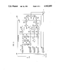
- FIG. 6 depicts a block diagram of decoder 300 of FIG. 1.
- FIG. 1 illustrates the basic communications system for practicing our invention. It includes a transmitter 10 within which there is an encoder 100 that is connected to a transmission channel 20. Channel 20 is connected to receiver 30, and within receiver 30 there is decoder 300 which is responsive to the signals flowing over channel 20. It should be understood, of course, that communication channel 20 is taken in its broadest sense, and it specifically includes a storage medium, such as a CDROM. That is, rather than sending encoded signals to a receiver in "real time", one can store the signals within the "channel”, and supply them to the user at some other time, upon request.
- a storage medium such as a CDROM.
- This concept encompasses, of course, situations that are not traditionally thought of as “communicating”; such as when the "transmitter” is a record manufacturer, the transmission “medium” is a purchased record, and the “receiver” is the “play-back” mechanism in the purchaser's home.
- FIG. 2 depicts a block diagram of encoder 100. It includes a filter bank block 110 to which the image signal is applied.
- the image signal can have any number of formats, and the standard raster format for two dimensional images is an acceptable one.
- filter bank 110 has four outputs, but it is understood that this can be any number greater than 1. These correspond to the four possible signals of an image that was filtered into a high band and a low band in both the horizontal dimension and vertical dimension. That is, two images are obtained by passing the image through a "horizontal low pass filter” and a "horizontal high pass filter”. By passing each of the two developed images through a "vertical low pass filter” and a "vertical high pass filter", four images are obtained. We call these four images the HH, HL, LH, and LL images.
- the LL image (low pass filtered both horizontally and vertically) contains the bulk of the relevant visual information.
- filters in filter bank 110 there is a high degree of correlation between the LL image and the other three images.
- FIG. 2 includes a coder 120 that is responsive to the LL image.
- Coder 120 encodes the LL image and aplies it to the transmission channel through multiplexer circuit 130. The very same signal is also fed to predictor coder block 140.
- the function of coder 120 is to compress the data from the LL band. This can be done in various ways, and the exact way by which that is done is of little importance to the principles of our invention.
- FIG. 2 shows a coder 120 that contains a DCT block 121 followed by block 122 that includes a quantizer and a Huffman encoder. Block 121 performs the discrete cosine transform on the filtered LL signal.
- the quantizer within block 122 reduces the number of different outputs that must be handled (lower dynamic range) and the Huffman coding encodes the outputs in a reduced number of bits.
- DCT block 121 can be constructed in conventional manner, and the Huffman coding can also be implemented in conventional manner, e.g., with a look-up table.
- Block 140 in FIG. 2 is a responsive to the HL, LH, and HH image signals on lines 102, 103, and 104, as well as to coder 120 signal on line 123.
- Predictor coder block 140 develops an estimate for each of the three image signals applied to it (HL, LH, and HH), compares the estimate to the actual signal, and encodes the difference found in the comparison.
- the encoded difference signals are applied to multiplexer 130.
- synthesis block 150 taps the previously described four signals sent to multiplexer 130 and decodes those signals.
- the output of synthesizer 150 is the decoded version of the signals applied by blocks 120 and 140 to the transmission channel, and is very close to the input image signal at line 101.
- This output signal is compared to the applied image signal of line 101 in subtracter 160, and the results of the comparison are applied to synthesis coder 170.
- Synthesis coder 170 transmits to multiplexer 130 information concerning the measure of error left in the encoding process of elements 110, 120 and 140.
- the filter bank (110) is charged with the responsibility of developing the four image signals LL, LH, HL, and HH.
- FIG. 3 illustrates one manner by which this can be accomplished for a raster scan input.
- the applied input signal is connected to a low pass filter 111 and a high pass filter 112.
- the outputs of the filters can be conventionally subsampled and, to that end, subsampling switches 113 and 114 are shown to be responsive to filters 111 and 112, respectively.
- Sub-sampling can be accomplished, for example, by ignoring every other sample, while up-samping can be accomplished by repeating a given sample.
- Transpose memories 115 and 116 are conventional memories where signals are stored in one way (following rows) but accessed in a different way (following columns). Such memory arrangements are well known in the art. For sake of completeness, however, the following simple implementation is suggested.
- To obtain transposition one may use an address counter and a memory responsive thereto, with a logic circuit interposed therebetween. The logic circuit allows for interchange of a number of least significant bits of the counter with higher significance bits of the counter. A normal sequence is thus obtained without the interchange of bits, and the transposed sequence is obtained by interchanging the bits.
- the output of memory 115 is applied to low pass filter 117 and to high pass filter 118.
- the output signal of memory 116 is applied to filters 161 and 162.
- the outputs of filters 117, 118, 161, and 162 are applied, respectively, to subsamplers 163, 164, 165, and 166, which produce the LL, LH, HL, and HH outputs of filter bank 110.
- the filters themselves can be implemented with short and simple finite impulse response (FIR) filters.
- a typical set of filter coefficients is [1,3,3,1] for the low pass filters (111, 117, and 161) and [1,3,-3,-1] for the high pass filters (112, 118, and 162).
- FIG. 4 presents a block diagram of predictor block 140.
- the output signal of coder 120 is applied via line 122 to Huffman decoder and dequantizer block 141, and the output of block 141 is applied to inverse DCT block 142.
- Blocks 142 and 141 reverse the operations of blocks 121 and 122, respectively.
- the result is the filtered signal LL, which is in the format of signals LH, HL, and HH.
- the output of block 142 is applied to filters 143, 144, and 145. These filters aim to predict the signals of the LH, HL, and HH bands, and since these bands contains primarily the edge information of the image, these filters are, basically, edge detectors.
- the edge detection can be effected with very simple two dimensional FIR filters with coefficients such as
- Filters 143-145 can also be implemented with a FIR filter like filter 111 in FIG. 3, followed by a transpose memory which, in turn, is followed by another FIR filter.
- the filter coefficients for filter element 143 are [1,2,1] and [1,0,-1]; the filter coefficients for filter element 144 are [1,0,-1] and [1,2,1]; and the filter coefficients for filter element 143 are [1,0,-1] and [1,0,-1].
- the outputs of filters 143, 144, and 145 are applied to threshold circuits 146, 147, and 148, respectively, and the outputs of threshold circuits 146, 147, and 148 are applied to comparators 167, 168, and 169, respectively.
- the threshold circuits which may or may not include amplification or attenuation means, aim to approximate the amplitude of the prediction signals to the incoming LH, HL, and HH signals, and to eliminate spurious responses from the filters. In the ultimate, the output of the threshold circuits can even be truncated to 1's and 0's.
- the LH, HL, and HH signals are also applied to the comparators, but through delay means 126, 127 and 128.
- the delay is necessary to compensate for the delay in the signal path from the LL output of filter bank 110 to the signal output of the threshold circuits.
- the output signals of comparators 167, 168, and 169 are applied to coders 123, 124, and 125, respectively, which can be constructed in a manner that is similar to the construction of coder 120.
- the outputs of coders 123, 124, and 125 comprise the output of predictor coder block 140.
- Synthesis block 150 simply reverses the encoding process. Its detailed description is reserved for the decoder discussion that follows. Suffice it to say that the output of synthesizer 150 approximates the input to filter bank 110. The output of synthesizer 150 is applied to subtracter 160, and the subtraction result is applied to synthesis coder 170. Synthesis coder 170 can be constructed in a manner that is similar to that of coder 120.
- Multiplexer 130 may be a conventional multiplexer. Its function is to allocate the samples developed by blocks 120, 140, and 170 to the communication channel. Its design can follow any conventional approach, and therefore, it is not discussed here in detail.
- FIG. 6 depicts a block diagram of decoder 300, which includes demultiplexer 184, synthesizer 150, decoder 180, and adder 183.
- the signal of channel 20 is applied to demultiplexer 184, where five signals are developed that correspond to the five signals that are combined in multiplexer 130. These are the encoded LL, LH, HL, and HH signals and the encoded error-correcting signal of synthesis coder 170.
- the first four signals (LL, LH, HL, and HH) signals are applied to synthesis block 150, whereas the fifth signal is connected to decoder 180.
- Decoders 189-191 are similar in construction to but reverse the operation of coders 123-125, respectively. They also include a delay to equalize the delay in the signal flow between the coders and subsequent circuits and the inverse DCT signals that feed those other circuits, as described below. This arrangement is very similar to the arrangement of the corresponding blocks in predictor block 140.
- the output of block 142 is applied to filters 196, 197, and 198 and the outputs of those filters are connected to threshold circuits 193, 194, and 195, respectively.
- Filters 196-198 and circuits 193-195 are similar to filters 143-145 and circuits 146-148 of FIG. 4, respectively.
- threshold circuit 193 is connected to adder 186 and the output of decoder 189 is also connected to adder 186.
- circuit 194 and decoder 190 are connected to adder 187, and circuit 195 and decoder 191 are connected to adder 188.
- the output signals of inverse DCT circuit 142 and the output signals of adders 186-188 are applied to combining circuit 200.
- the signals are up-sampled in up-samplers 201-204, filtered and combined. Specifically, after up-sampling, the signal of block 142 is applied to a low pass filter (205), the signal of adder 186 is applied to a high pass filter (206), the signal of adder 187 is applied to a low pass filer (207), and, lastly, the signal of adder 188 is applied to a high pass filter (208). Still within combining network 200, the output signal of filters 205 and 206 are applied to an adder (209) and then to transpose memory 210.
- the output signals of filters 207 and 208 are applied to an adder (211) and then to transpose memory 212.
- the output of memories 210 and 212 are up-sampled again in elements 213 and 214, and respectively passed through a low pass filter (215) and a high pass filter (216).
- the signal sum of the outputs of filters 215 and 216 is developed in adder 217, which provides the output of combining block 200 and the output of synthesis block 150.
- Filters 205-208 and 215-216 are each three stage filters.
- the coefficients of the low pass filters is [1,-3,-3,1] and the coefficients of the high pass filters is [-1,3,-3,1].
- decoder 300 In applications where the transmissionn side does not use synthesis coder block 170, the output of block 150 in decoder 300 forms the output of the decoder. In applications where synthesis coder 170 is used, decoder 300 includes decoder block 180 and adder block 183 that is responsive to the output of decoder 180 and block 150. In those circumstances, the output of adder 183 forms the output of decoder 300.
Abstract
Description
[1, 0, -1]
[2, 0, -2]
[1, 0, -1]
Claims (13)
Priority Applications (1)
| Application Number | Priority Date | Filing Date | Title |
|---|---|---|---|
| US07/222,987 US4943855A (en) | 1988-07-22 | 1988-07-22 | Progressive sub-band image coding system |
Applications Claiming Priority (1)
| Application Number | Priority Date | Filing Date | Title |
|---|---|---|---|
| US07/222,987 US4943855A (en) | 1988-07-22 | 1988-07-22 | Progressive sub-band image coding system |
Publications (1)
| Publication Number | Publication Date |
|---|---|
| US4943855A true US4943855A (en) | 1990-07-24 |
Family
ID=22834529
Family Applications (1)
| Application Number | Title | Priority Date | Filing Date |
|---|---|---|---|
| US07/222,987 Expired - Lifetime US4943855A (en) | 1988-07-22 | 1988-07-22 | Progressive sub-band image coding system |
Country Status (1)
| Country | Link |
|---|---|
| US (1) | US4943855A (en) |
Cited By (38)
| Publication number | Priority date | Publication date | Assignee | Title |
|---|---|---|---|---|
| US5049992A (en) * | 1990-08-27 | 1991-09-17 | Zenith Electronics Corporation | HDTV system with receivers operable at different levels of resolution |
| US5163103A (en) * | 1988-12-27 | 1992-11-10 | Kabushiki Kaisha Toshiba | Discrete cosine transforming apparatus |
| US5218435A (en) * | 1991-02-20 | 1993-06-08 | Massachusetts Institute Of Technology | Digital advanced television systems |
| US5307143A (en) * | 1991-01-11 | 1994-04-26 | Samsung Electronics Co., Ltd. | Method and circuit for transmitting a direct current component of a color signal |
| US5317413A (en) * | 1991-11-12 | 1994-05-31 | Sony Corporation | Digital high-definition video signal recording and reproducing apparatus |
| US5337049A (en) * | 1991-10-01 | 1994-08-09 | Kabushiki Kaisha Toshiba | Efficient coding signal processor |
| US5382979A (en) * | 1991-07-26 | 1995-01-17 | Samsung Electronics Co., Ltd. | Method and circuit for adaptively selecting three-dimensional sub-band image signal |
| US5426673A (en) * | 1994-02-09 | 1995-06-20 | The Regents Of The University Of California | Discrete cosine transform-based image coding and decoding method |
| US5450132A (en) * | 1989-06-13 | 1995-09-12 | Utah State University Foundation | Method and apparatus for data compression with reduced distortion |
| US5481308A (en) * | 1992-02-07 | 1996-01-02 | At&T Corp. | Method and apparatus for synthesizing subband video images |
| US5541594A (en) * | 1994-03-28 | 1996-07-30 | Utah State University Foundation | Fixed quality source coder with fixed threshold |
| US5568199A (en) * | 1992-11-25 | 1996-10-22 | Matsushita Electric Industrial Co., Ltd. | Digital video signal code size control apparatus |
| US5629737A (en) * | 1992-06-30 | 1997-05-13 | International Business Machines Corporation | Method and apparatus for subband coding video signals |
| US5633684A (en) * | 1993-12-29 | 1997-05-27 | Victor Company Of Japan, Ltd. | Image information compression and decompression device |
| US5682441A (en) * | 1995-11-08 | 1997-10-28 | Storm Technology, Inc. | Method and format for storing and selectively retrieving image data |
| US5699363A (en) * | 1994-07-20 | 1997-12-16 | Mms Space Systems Unlimited | Digital signal processing apparatus |
| US5719627A (en) * | 1995-02-28 | 1998-02-17 | Nec Corporation | System and method for motion compensation on sub-band represented signals of motion picture |
| USH1714H (en) * | 1995-05-03 | 1998-03-03 | Lucent Technologies Inc. | Automatic still image transmission upon call connection |
| US5781888A (en) * | 1996-01-16 | 1998-07-14 | Lucent Technologies Inc. | Perceptual noise shaping in the time domain via LPC prediction in the frequency domain |
| US5790695A (en) * | 1992-10-15 | 1998-08-04 | Sharp Kabushiki Kaisha | Image coding device for coding image signal to reduce the amount of the information in the image |
| US5812971A (en) * | 1996-03-22 | 1998-09-22 | Lucent Technologies Inc. | Enhanced joint stereo coding method using temporal envelope shaping |
| US5844612A (en) * | 1995-11-09 | 1998-12-01 | Utah State University Foundation | Motion vector quantizing selection system |
| US5909513A (en) * | 1995-11-09 | 1999-06-01 | Utah State University | Bit allocation for sequence image compression |
| US5926209A (en) * | 1995-07-14 | 1999-07-20 | Sensormatic Electronics Corporation | Video camera apparatus with compression system responsive to video camera adjustment |
| US5973739A (en) * | 1992-03-27 | 1999-10-26 | British Telecommunications Public Limited Company | Layered video coder |
| US6072910A (en) * | 1989-03-10 | 2000-06-06 | Canon Kabushiki Kaisha | Method and apparatus for coding image information, and method of creating code book |
| US6134350A (en) * | 1998-02-18 | 2000-10-17 | Dome Imaging Systems, Inc. | Method of producing wavelets and compressing digital images and of restoring the digital images |
| US6215908B1 (en) * | 1999-02-24 | 2001-04-10 | Intel Corporation | Symmetric filtering based VLSI architecture for image compression |
| US6298163B1 (en) | 1997-02-12 | 2001-10-02 | Sarnoff Corporation | Apparatus and method for encoding wavelet trees generated by a wavelet-based coding method using band dependent tables |
| US6546143B1 (en) * | 1999-03-12 | 2003-04-08 | Hewlett-Packard Development Company | Efficient wavelet-based compression of large images |
| US20030190084A1 (en) * | 1994-11-10 | 2003-10-09 | Kabushiki Kaisha Toshiba | Image data coding and/or decoding system capable of high-efficient coding |
| US20040001547A1 (en) * | 2002-06-26 | 2004-01-01 | Debargha Mukherjee | Scalable robust video compression |
| US6683957B1 (en) * | 1998-07-01 | 2004-01-27 | Samsung Electronics Co., Ltd. | Digital image coding/decoding apparatus and method for correcting distorted data in transmitted signals that use watermarking |
| US6711297B1 (en) | 1998-07-03 | 2004-03-23 | University Of Pittsburgh - Of The Commonwealth System Of Higher Education | Methods and apparatus for dynamic transfer of image data |
| EP1107607A3 (en) * | 1999-12-10 | 2004-04-21 | Xerox Corporation | JPEG compression method |
| US6925208B1 (en) | 2002-05-04 | 2005-08-02 | Stentor, Inc. | Methods and apparatus for partitioning transform data |
| US6978048B1 (en) * | 1999-03-12 | 2005-12-20 | Canon Kabushiki Kaisha | Encoding method and apparatus |
| US20080040103A1 (en) * | 2004-08-25 | 2008-02-14 | Dolby Laboratories Licensing Corporation | Temporal envelope shaping for spatial audio coding using frequency domain wiener filtering |
Citations (5)
| Publication number | Priority date | Publication date | Assignee | Title |
|---|---|---|---|---|
| US4663660A (en) * | 1986-06-20 | 1987-05-05 | Rca Corporation | Compressed quantized image-data transmission technique suitable for use in teleconferencing |
| US4831636A (en) * | 1985-06-28 | 1989-05-16 | Fujitsu Limited | Coding transmission equipment for carrying out coding with adaptive quantization |
| US4864396A (en) * | 1987-05-27 | 1989-09-05 | U.S. Philips Corporation | Television transmission system including a pyramidal coding/decoding circuit |
| US4870497A (en) * | 1988-01-22 | 1989-09-26 | American Telephone And Telegraph Company | Progressive transmission of high resolution two-tone facsimile images |
| US4873577A (en) * | 1988-01-22 | 1989-10-10 | American Telephone And Telegraph Company | Edge decomposition for the transmission of high resolution facsimile images |
-
1988
- 1988-07-22 US US07/222,987 patent/US4943855A/en not_active Expired - Lifetime
Patent Citations (5)
| Publication number | Priority date | Publication date | Assignee | Title |
|---|---|---|---|---|
| US4831636A (en) * | 1985-06-28 | 1989-05-16 | Fujitsu Limited | Coding transmission equipment for carrying out coding with adaptive quantization |
| US4663660A (en) * | 1986-06-20 | 1987-05-05 | Rca Corporation | Compressed quantized image-data transmission technique suitable for use in teleconferencing |
| US4864396A (en) * | 1987-05-27 | 1989-09-05 | U.S. Philips Corporation | Television transmission system including a pyramidal coding/decoding circuit |
| US4870497A (en) * | 1988-01-22 | 1989-09-26 | American Telephone And Telegraph Company | Progressive transmission of high resolution two-tone facsimile images |
| US4873577A (en) * | 1988-01-22 | 1989-10-10 | American Telephone And Telegraph Company | Edge decomposition for the transmission of high resolution facsimile images |
Non-Patent Citations (8)
| Title |
|---|
| IEEE Transactions on Acoustics, Speech, and Signal Processing, vol. ASSP 34, No. 5, 10/86, Subband Coding of Images , J. W. Woods et al., pp. 1278 1279. * |
| IEEE Transactions on Acoustics, Speech, and Signal Processing, vol. ASSP-34, No. 5, 10/86, "Subband Coding of Images", J. W. Woods et al., pp. 1278-1279. |
| IEEE Transactions on Communications, vol. COM 25, No. 11, Nov. 1977, Adaptive Coding of Monochrome and Color Images, W. Chen et al., pp. 1285 1292. * |
| IEEE Transactions on Communications, vol. COM-25, No. 11, Nov. 1977, "Adaptive Coding of Monochrome and Color Images," W. Chen et al., pp. 1285-1292. |
| SPIE vol. 707 Visual Communications and Image Processing, 1986, "Sub-Band Coding of Digital Images Using Two-Dimensional Quadrature Mirror Filtering", H. Gharavi et al., pp. 51-61. |
| SPIE vol. 707 Visual Communications and Image Processing, 1986, Sub Band Coding of Digital Images Using Two Dimensional Quadrature Mirror Filtering , H. Gharavi et al., pp. 51 61. * |
| The Bell System Technical Journal, vol. 55, No. 8 10/76, "Digital Coding of Speech in Sub-Bands", R. E. Crochiere et al., pp 1069-1085. |
| The Bell System Technical Journal, vol. 55, No. 8 10/76, Digital Coding of Speech in Sub Bands , R. E. Crochiere et al., pp 1069 1085. * |
Cited By (50)
| Publication number | Priority date | Publication date | Assignee | Title |
|---|---|---|---|---|
| US5163103A (en) * | 1988-12-27 | 1992-11-10 | Kabushiki Kaisha Toshiba | Discrete cosine transforming apparatus |
| US6072910A (en) * | 1989-03-10 | 2000-06-06 | Canon Kabushiki Kaisha | Method and apparatus for coding image information, and method of creating code book |
| US5450132A (en) * | 1989-06-13 | 1995-09-12 | Utah State University Foundation | Method and apparatus for data compression with reduced distortion |
| US5049992A (en) * | 1990-08-27 | 1991-09-17 | Zenith Electronics Corporation | HDTV system with receivers operable at different levels of resolution |
| US5307143A (en) * | 1991-01-11 | 1994-04-26 | Samsung Electronics Co., Ltd. | Method and circuit for transmitting a direct current component of a color signal |
| US5218435A (en) * | 1991-02-20 | 1993-06-08 | Massachusetts Institute Of Technology | Digital advanced television systems |
| US5485210A (en) * | 1991-02-20 | 1996-01-16 | Massachusetts Institute Of Technology | Digital advanced television systems |
| US5382979A (en) * | 1991-07-26 | 1995-01-17 | Samsung Electronics Co., Ltd. | Method and circuit for adaptively selecting three-dimensional sub-band image signal |
| US5337049A (en) * | 1991-10-01 | 1994-08-09 | Kabushiki Kaisha Toshiba | Efficient coding signal processor |
| AU659887B2 (en) * | 1991-11-12 | 1995-06-01 | Sony Corporation | Digital video signal recording and reproducing apparatus |
| US5317413A (en) * | 1991-11-12 | 1994-05-31 | Sony Corporation | Digital high-definition video signal recording and reproducing apparatus |
| US5481308A (en) * | 1992-02-07 | 1996-01-02 | At&T Corp. | Method and apparatus for synthesizing subband video images |
| US5973739A (en) * | 1992-03-27 | 1999-10-26 | British Telecommunications Public Limited Company | Layered video coder |
| US5629737A (en) * | 1992-06-30 | 1997-05-13 | International Business Machines Corporation | Method and apparatus for subband coding video signals |
| US5790695A (en) * | 1992-10-15 | 1998-08-04 | Sharp Kabushiki Kaisha | Image coding device for coding image signal to reduce the amount of the information in the image |
| US5568199A (en) * | 1992-11-25 | 1996-10-22 | Matsushita Electric Industrial Co., Ltd. | Digital video signal code size control apparatus |
| US5633684A (en) * | 1993-12-29 | 1997-05-27 | Victor Company Of Japan, Ltd. | Image information compression and decompression device |
| US5426673A (en) * | 1994-02-09 | 1995-06-20 | The Regents Of The University Of California | Discrete cosine transform-based image coding and decoding method |
| US5541594A (en) * | 1994-03-28 | 1996-07-30 | Utah State University Foundation | Fixed quality source coder with fixed threshold |
| US5699363A (en) * | 1994-07-20 | 1997-12-16 | Mms Space Systems Unlimited | Digital signal processing apparatus |
| US20050129321A1 (en) * | 1994-11-10 | 2005-06-16 | Kabushiki Kaisha Toshiba | Image data coding and/or decoding system capable of high-efficient coding |
| US7054495B2 (en) | 1994-11-10 | 2006-05-30 | Kabushiki Kaisha Toshiba | Image data coding and/or decoding system capable of high-efficient coding |
| US20030190084A1 (en) * | 1994-11-10 | 2003-10-09 | Kabushiki Kaisha Toshiba | Image data coding and/or decoding system capable of high-efficient coding |
| US6868184B2 (en) | 1994-11-10 | 2005-03-15 | Kabushiki Kaisha Toshiba | Method and apparatus for image coding and/or decoding using a position and shape map |
| US6697531B2 (en) * | 1994-11-10 | 2004-02-24 | Kabushiki Kaisha Toshiba | Image coding and decoding using a position and shape map |
| US20030198396A1 (en) * | 1994-11-10 | 2003-10-23 | Kabushiki Kaisha Toshiba | Image data coding and/or decoding system capable of high-efficient coding |
| US5719627A (en) * | 1995-02-28 | 1998-02-17 | Nec Corporation | System and method for motion compensation on sub-band represented signals of motion picture |
| USH1714H (en) * | 1995-05-03 | 1998-03-03 | Lucent Technologies Inc. | Automatic still image transmission upon call connection |
| US5926209A (en) * | 1995-07-14 | 1999-07-20 | Sensormatic Electronics Corporation | Video camera apparatus with compression system responsive to video camera adjustment |
| US5682441A (en) * | 1995-11-08 | 1997-10-28 | Storm Technology, Inc. | Method and format for storing and selectively retrieving image data |
| US6137914A (en) * | 1995-11-08 | 2000-10-24 | Storm Software, Inc. | Method and format for storing and selectively retrieving image data |
| US5844612A (en) * | 1995-11-09 | 1998-12-01 | Utah State University Foundation | Motion vector quantizing selection system |
| US5909513A (en) * | 1995-11-09 | 1999-06-01 | Utah State University | Bit allocation for sequence image compression |
| US5781888A (en) * | 1996-01-16 | 1998-07-14 | Lucent Technologies Inc. | Perceptual noise shaping in the time domain via LPC prediction in the frequency domain |
| US5812971A (en) * | 1996-03-22 | 1998-09-22 | Lucent Technologies Inc. | Enhanced joint stereo coding method using temporal envelope shaping |
| US6298163B1 (en) | 1997-02-12 | 2001-10-02 | Sarnoff Corporation | Apparatus and method for encoding wavelet trees generated by a wavelet-based coding method using band dependent tables |
| US6134350A (en) * | 1998-02-18 | 2000-10-17 | Dome Imaging Systems, Inc. | Method of producing wavelets and compressing digital images and of restoring the digital images |
| US6683957B1 (en) * | 1998-07-01 | 2004-01-27 | Samsung Electronics Co., Ltd. | Digital image coding/decoding apparatus and method for correcting distorted data in transmitted signals that use watermarking |
| US7280702B2 (en) | 1998-07-03 | 2007-10-09 | Koninklijke Philips Electronics N.V. | Methods and apparatus for dynamic transfer of image data |
| US6711297B1 (en) | 1998-07-03 | 2004-03-23 | University Of Pittsburgh - Of The Commonwealth System Of Higher Education | Methods and apparatus for dynamic transfer of image data |
| US20040179744A1 (en) * | 1998-07-03 | 2004-09-16 | Chang Paul Joseph | Methods and apparatus for dynamic transfer of image data |
| US6215908B1 (en) * | 1999-02-24 | 2001-04-10 | Intel Corporation | Symmetric filtering based VLSI architecture for image compression |
| US6978048B1 (en) * | 1999-03-12 | 2005-12-20 | Canon Kabushiki Kaisha | Encoding method and apparatus |
| US6546143B1 (en) * | 1999-03-12 | 2003-04-08 | Hewlett-Packard Development Company | Efficient wavelet-based compression of large images |
| EP1107607A3 (en) * | 1999-12-10 | 2004-04-21 | Xerox Corporation | JPEG compression method |
| US6925208B1 (en) | 2002-05-04 | 2005-08-02 | Stentor, Inc. | Methods and apparatus for partitioning transform data |
| WO2004004358A1 (en) * | 2002-06-26 | 2004-01-08 | Hewlett-Packard Development Company, L.P. | Scalable robust video compression |
| US20040001547A1 (en) * | 2002-06-26 | 2004-01-01 | Debargha Mukherjee | Scalable robust video compression |
| US20080040103A1 (en) * | 2004-08-25 | 2008-02-14 | Dolby Laboratories Licensing Corporation | Temporal envelope shaping for spatial audio coding using frequency domain wiener filtering |
| CN102270453B (en) * | 2004-08-25 | 2014-06-18 | 杜比实验室特许公司 | Temporal envelope shaping for spatial audio coding using frequency domain wiener filtering |
Similar Documents
| Publication | Publication Date | Title |
|---|---|---|
| US4943855A (en) | Progressive sub-band image coding system | |
| Karlsson et al. | Three dimensional sub-band coding of video | |
| KR100781629B1 (en) | A method for reducing the memory required for decompression by storing compressed information using DCT base technology and a decoder for implementing the method | |
| US6005623A (en) | Image conversion apparatus for transforming compressed image data of different resolutions wherein side information is scaled | |
| US5311310A (en) | High efficiency coder and method employing overlapped motion compensation and perfect reconstruction filter banks | |
| US7054493B2 (en) | Context generation | |
| US7512180B2 (en) | Hierarchical data compression system and method for coding video data | |
| EP0555016B1 (en) | Dynamic bit allocation for three-dimensional subband video coding | |
| Ho et al. | Classified transform coding of images using vector quantization | |
| US5808683A (en) | Subband image coding and decoding | |
| EP0734164B1 (en) | Video signal encoding method and apparatus having a classification device | |
| EP0575201A2 (en) | Coding and decoding | |
| US5337085A (en) | Coding technique for high definition television signals | |
| JPH04229791A (en) | Device used for video coding system | |
| US20050163217A1 (en) | Method and apparatus for coding and decoding video bitstream | |
| US5629737A (en) | Method and apparatus for subband coding video signals | |
| US20050129319A1 (en) | Fast discrete wavelet encoding apparatus and method for encoding a still image at a high speed based on energy of each block | |
| Vandendorpe | Hierarchical transform and subband coding of video signals | |
| KR100675392B1 (en) | Transmitting/ receiving device for transmitting/receiving a digital information signal and method thereof | |
| JP2705228B2 (en) | Sub-band coding for image signals | |
| EP0762773B1 (en) | Hierarchial video encoder and decoder | |
| Karlsson | Subband coding for packet video | |
| Darragh et al. | Fixed distortion, variable rate subband coding of images | |
| JPH03295378A (en) | Picture decoding device | |
| Hong | Sub-band coding of video using two-dimensional adaptive deltamodulation for packet video applications |
Legal Events
| Date | Code | Title | Description |
|---|---|---|---|
| AS | Assignment |
Owner name: BELL TELEPHONE LABORATORIES, INCORPORATED, 600 MOU Free format text: ASSIGNMENT OF ASSIGNORS INTEREST.;ASSIGNORS:BHEDA, HEMANT;LIGTENBERG, ADRIANUS;REEL/FRAME:004914/0991 Effective date: 19880630 Owner name: AMERICAN TELEPHONE AND TELEGRAPH COMPANY, 550 MADI Free format text: ASSIGNMENT OF ASSIGNORS INTEREST.;ASSIGNORS:BHEDA, HEMANT;LIGTENBERG, ADRIANUS;REEL/FRAME:004914/0991 Effective date: 19880630 |
|
| STCF | Information on status: patent grant |
Free format text: PATENTED CASE |
|
| FEPP | Fee payment procedure |
Free format text: PAYOR NUMBER ASSIGNED (ORIGINAL EVENT CODE: ASPN); ENTITY STATUS OF PATENT OWNER: LARGE ENTITY |
|
| FPAY | Fee payment |
Year of fee payment: 4 |
|
| FEPP | Fee payment procedure |
Free format text: PAYER NUMBER DE-ASSIGNED (ORIGINAL EVENT CODE: RMPN); ENTITY STATUS OF PATENT OWNER: LARGE ENTITY Free format text: PAYOR NUMBER ASSIGNED (ORIGINAL EVENT CODE: ASPN); ENTITY STATUS OF PATENT OWNER: LARGE ENTITY |
|
| FEPP | Fee payment procedure |
Free format text: PAYER NUMBER DE-ASSIGNED (ORIGINAL EVENT CODE: RMPN); ENTITY STATUS OF PATENT OWNER: LARGE ENTITY Free format text: PAYOR NUMBER ASSIGNED (ORIGINAL EVENT CODE: ASPN); ENTITY STATUS OF PATENT OWNER: LARGE ENTITY |
|
| FPAY | Fee payment |
Year of fee payment: 8 |
|
| FPAY | Fee payment |
Year of fee payment: 12 |