US4954781A - Nuclear magnetic resonance imaging apparatus with reduced acoustic noise - Google Patents
Nuclear magnetic resonance imaging apparatus with reduced acoustic noise Download PDFInfo
- Publication number
- US4954781A US4954781A US07/362,950 US36295089A US4954781A US 4954781 A US4954781 A US 4954781A US 36295089 A US36295089 A US 36295089A US 4954781 A US4954781 A US 4954781A
- Authority
- US
- United States
- Prior art keywords
- magnetic resonance
- nuclear magnetic
- resin
- gradient
- viscoelastic layer
- Prior art date
- Legal status (The legal status is an assumption and is not a legal conclusion. Google has not performed a legal analysis and makes no representation as to the accuracy of the status listed.)
- Expired - Lifetime
Links
Images


Classifications
-
- G—PHYSICS
- G01—MEASURING; TESTING
- G01R—MEASURING ELECTRIC VARIABLES; MEASURING MAGNETIC VARIABLES
- G01R33/00—Arrangements or instruments for measuring magnetic variables
- G01R33/20—Arrangements or instruments for measuring magnetic variables involving magnetic resonance
- G01R33/28—Details of apparatus provided for in groups G01R33/44 - G01R33/64
- G01R33/38—Systems for generation, homogenisation or stabilisation of the main or gradient magnetic field
- G01R33/385—Systems for generation, homogenisation or stabilisation of the main or gradient magnetic field using gradient magnetic field coils
- G01R33/3854—Systems for generation, homogenisation or stabilisation of the main or gradient magnetic field using gradient magnetic field coils means for active and/or passive vibration damping or acoustical noise suppression in gradient magnet coil systems
Definitions
- the present invention relates to a nuclear magnetic resonance imaging apparatus for obtaining tomographic images of a body to be examined by utilizing a phenomenon of nuclear magnetic resonance.
- a nuclear magnetic resonance imaging apparatus provides an important means for analyzing atomic and electronic structures of matter or chemical compounds in a solid state and an organic chemistry research. Also, there are increasing uses in medical practice of the nuclear magnetic resonance imaging apparatus as a diagnostic device for obtaining tomographic images of arbitrary cross sections of a body to be examined, on a basis of such information as hydrogen distribution and spin relaxation times extracted by utilizing a nuclear magnetic resonance phenomenon.
- FIGS. 1 and 2 A main portion of a conventional nuclear magnetic resonance imaging apparatus is shown in perspective view and in cross sectional view in FIGS. 1 and 2, respectively.
- a main magnet 1 with bore for generating a static magnetic field
- a hollow cylindrical outer shell 2 inside the bore which is connected to the main magnet 1 by supporting member 3
- a hollow cylindrical inner shell 7 inside the outer shell 2 which is connected to the outer shell 2 by ring members 8.
- a gradient coil 21 for producing gradient magnetic field which is connected to the outer shell 2 by means of first gradient coil supporting member 4, a second gradient coil supporting member 5 and a support rubber 6.
- the gradient coil 21 comprises a X-coil 25, a Y-coil 27, and a Z-coil 29 wound around a coil core 23, each of which produces the gradient field in X-, Y, and Z-directions, respectively.
- these X-coil 25, Y-coil 27, and Z-coil 29 are fixed on the coil core 23 by molding with a non-magnetic resin 24 with a relatively large Young'3 s modulus, such as epoxy resin.
- Each of these X-coil 25, Y-coil 27, and Z-coil 29 is provided with a separate power source, so that pulsed current for producing the gradient field can be applied separately when taking measurements.
- the gradient coil 21 is confined inside a space formed by the outer shell 2, the inner shell 7 and the ring members 8 so as to muffle such acoustic noise, there still is a significant amount of vibration of the outer shell 2 caused by the vibration of the gradient coil 21 mediated through the air and through the first gradient coil supporting member 4, the second gradient coil supporting member 5 and the support rubber 6, as well as through the ring members 8.
- the noises may also be produced by the vibration of the coil core 23 and the resin 24.
- a nuclear magnetic resonance imaging apparatus comprising: a main magnet for generating a static magnetic field in a measurement space in which a body to be examined is to be placed: gradient coil means for producing gradient magnetic fields over the static magnetic field: means for detecting signals from the body in the static and gradient magnetic fields due to a nuclear magnetic resonance phenomenon: means for processing the detected signals so as to obtain tomographic images of the body at arbitrary cross sections: and a sandwich structure which is located between the body an the main magnet, comprising a viscoelastic layer sandwiched by a first and a second sandwiching members.
- a nuclear magnetic resonance imaging apparatus comprising: a main magnet for generating a static magnetic field in a measurement space in which a body to be examined is to be placed; gradient coil means for producing gradient magnetic fields over the static magnetic field; means for detecting signals from the body in the static and gradient magnetic fields due to a nuclear magnetic resonance phenomenon; means for processing the detected signals so as to obtain tomographic images of the body at arbitrary cross sections; and a hollow member which is located between the measurement space and the main magnet, including a viscoelastic layer.
- a nuclear magnetic resonance imaging apparatus comprising: a main magnet for generating a static magnetic field in a measurement space in which a body to be examined is to be placed; gradient coil means for producing gradient magnetic fields over the static magnetic field, the gradient coil means being comprised of coils wound around a coil core, a first resin molding the coils, and a second resin having a larger stiffness than the first resin, the second resin surrounding the first resin, at least one of inside the second resin and between the first resin and second resin containing a viscoelastic layer; means for detecting signals from the body in the static and gradient magnetic fields due to a nuclear magnetic resonance phenomenon; and means for processing the detected signals so as to obtain tomographic images of the body at arbitrary cross sections.
- a nuclear magnetic resonance imaging apparatus comprising: a main magnet for generating a static magnetic field in a measurement space in which a body to be examined is to be placed; gradient coil means for producing gradient magnetic fields over the static magnetic field, comprising a coil core which contains a viscoelastic layer, and coils wound around the coil core; means for detecting signals from the body in the static and gradient magnetic fields due to a nuclear magnetic resonance phenomenon; and means for processing the detected signals so as to obtain tomographic images of the body at arbitrary cross sections.
- a nuclear magnetic resonance imaging apparatus comprising: a main magnet for generating a static magnetic field in a measurement space in which a body to be examined is to be placed; gradient coil means for producing gradient magnetic fields over the static magnetic field, comprising a coil core, coils wound around the coil core, and a resin molding the coils, at least one of inside the resin and between the coil core and resin containing a viscoelastic layer; means for detecting signals from the body in the static and gradient magnetic fields due to a nuclear magnetic resonance phenomenon; and means for processing the detected signals so as to obtain tomographic images of the body at arbitrary cross sections.
- a nuclear magnetic resonance imaging apparatus comprising: a main magnet for generating a static magnetic field in a measurement space in which a body to be examined is to be placed; gradient coil means for producing gradient magnetic fields over the static magnetic field; means for detecting signals from the body in the static and gradient magnetic fields due to a nuclear magnetic resonance phenomenon; means for processing the detected signals so as to obtain tomographic images of the body at arbitrary cross sections; and a hollow member which supports the gradient coil means against the main magnet, and is located between the measurement space and the main magnet, including a viscoelastic layer.
- FIG. 1 is a perspective view of a main portion of a conventional nuclear magnetic resonance imaging apparatus.
- FIG. 2 is a cross sectional view of a main portion of the conventional nuclear magnetic resonance imaging apparatus of FIG. 1.
- FIG. 3 is a perspective view of a gradient coil of the conventional nuclear magnetic resonance imaging apparatus of FIG. 1.
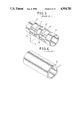
- FIG. 4 is a perspective view of a coil core and a resin mold for the gradient coil of FIG. 3.
- FIG. 5 is a perspective view of a main portion of the first embodiment of a nuclear magnetic resonance imaging apparatus according to the present invention.
- FIG. 6 is a cross sectional view of a main portion of the nuclear magnetic resonance imaging apparatus of FIG. 5.
- FIGS. 7(A) and 7(B) are a graph of frequency characteristic of currents in a gradient coil and a diagram of force due to the currents, respectively, for the nuclear magnetic resonance imaging apparatus of FIG. 5.
- FIGS. 8(A) and 8(B) are a graph of frequency characteristic of vibrations in the gradient coil and a diagram of vibration modes of the gradient coil, respectively, for the nuclear magnetic resonance imaging apparatus of FIG. 5.
- FIGS. 9(A) and 9(B) are a graph of frequency characteristic of vibrations in a transmitter and receiver coil and a diagram of vibration modes of the transmitter and receiver coil, respectively, for the nuclear magnetic resonance imaging apparatus of FIG. 5.
- FIGS. 10(A) and 10(B) are graphs of frequency characteristic and positional variation of acoustic noises, respectively for the nuclear magnetic resonance imaging apparatus of FIG. 5.
- FIG. 11 is a cross sectional view of a main portion of a nuclear magnetic resonance imaging apparatus according to the first embodiment with which the experiments had been conducted.
- FIG. 12 is a diagrammatic illustration of an inner shell of the nuclear magnetic resonance imaging apparatus of FIG. 11 for explaining a position where the measurement of the acceleration had been taken in the first experiment.
- FIG. 13 is a graph of frequency characteristic of vibrations in an inner shell for both a conventional nuclear magnetic resonance imaging apparatus and the nuclear magnetic resonance imaging apparatus of FIG. 11, obtained by the first experiment.
- FIG. 14 is an illustration of a cross section of a sandwich structure around viscoelastic layer in the nuclear magnetic resonance imaging apparatus of FIG. 5, for explaining shearing deformation arising in the sandwich structure.
- FIG. 15 is a perspective illustration of the sandwich structure of FIG. 14, for explaining the reduction of acoustic noise achieved by the sandwich structure.
- FIG. 16 is a graph of a dimensionless parameter ⁇ appearing in analysis of the reduction of acoustic noise achieved by the sandwich structure, as functions of two other parameters R 0 and r 1 appearing in the same analysis for explaining the preferable conditions for the sandwich structure.
- FIG. 17 is a perspective view of a main portion of the second embodiment of a nuclear magnetic resonance imaging apparatus according to the present invention.
- FIG. 18 is a cross sectional view of a main portion of the nuclear magnetic resonance imaging apparatus of FIG. 17.
- FIG. 19 is a diagrammatic illustration of an inner shell of the nuclear magnetic resonance imaging apparatus of FIG. 17 for explaining positions where the measurements of the acceleration had been taken in the second experiment.
- FIG. 20 is another diagrammatic illustration of an inner shell of the nuclear magnetic resonance imaging apparatus of FIG. 17 for explaining positions where the measurement of the acoustic noise had been taken in the experiment.
- FIG. 21 is a graph of the acceleration as a function of time measured at one location inside the measurement space in the second experiment.
- FIG. 22 is another graph of the acceleration as a function of time measured at another location inside the measurement space in the second experiment.
- FIG. 23 is a graph of acoustic noise level measured at various location inside the measurement space in the second experiment.
- FIG. 24 is a perspective view of a main portion of the third embodiment of a nuclear magnetic resonance imaging apparatus according to the present invention.
- FIG. 25 is a cross sectional view of a main portion of the nuclear magnetic resonance imaging apparatus of FIG. 24.
- FIG. 26 is a cross sectional view of a main portion of the fourth embodiment of a nuclear magnetic resonance imaging apparatus according to the present invention.
- FIG. 27 is a cross sectional view of a main portion of the fifth embodiment of a nuclear magnetic resonance imaging apparatus according to the present invention.
- FIG. 28 is a cross sectional view of a main portion of the sixth embodiment of a nuclear magnetic resonance imaging apparatus according to the present invention.
- FIGS. 5 and 6 there is shown a first embodiment of a nuclear magnetic resonance imaging apparatus according to the present invention.
- a viscoelastic layer 9 made of polymer compounds such as butyl rubber, silicon rubber, polysulfide rubber, urethane rubber, fluoro rubber, polyvinyl chloride acetate, Neoprene rubber(Trade Name), and VEM(Trade Name) between a gradient coil 21 and a body to be examined which will be placed in a measurement space inside the bore of an inner shell 7.
- a viscoelastic layer 9, for example can be formed in a middle of the inner shell 7, as shown in FIGS. 5 and 6, by pouring liquid viscoelastic material into a hollow region prepared in the inner shell 7.
- this viscoelastic layer 9 for the purpose of reducing acoustic noises is based on the following analysis due to the present inventor, of the mechanism of generation and propagation of acoustic noises in a nuclear magnetic resonance imaging apparatus, which has been largely unknown heretofore.
- FIGS. 7 to 10 show a route of ⁇ force due to currents in the gradient coil 21> ⁇ vibration of the gradient coil 21> ⁇ vibration of the inner shell 7> ⁇ acoustic noises>.
- FIGS. 7 to 10 show a route of ⁇ force due to currents in the gradient coil 21> ⁇ vibration of the gradient coil 21> ⁇ vibration of the inner shell 7> ⁇ acoustic noises>.
- FIGS. 7 to 10 shows a graph of frequency characteristic of currents in the gradient coil 21 and FIG. 7(B) shows a diagram of force F due to the currents I in the gradient coil 21 along with the direction of the static magnetic field B generated by the main magnet 1, while FIG. 8(A) show a graph of frequency characteristic of vibrations in the gradient coil 21 in terms of instantaneous acceleration and FIG.
- FIG. 8(B) shows a diagram of vibration modes of the gradient coil 21, i.e., extreme configurations of the gradient coil 21.
- FIG. 9(A) shows a graph of frequency characteristics of vibrations in the inner shell 7 in terms of instantaneous acceleration
- FIG. 9(B) shows a diagram of vibration modes of the inner shell 7, i.e. extreme configurations of the inner shell 7,
- FIGS. 10(A) and 10(B) show graphs of frequency characteristic and positional variation of acoustic noises along a central axis of the measurement space, respectively.
- the gradient coil 21 is fed with a pulsed current shown in FIG. 7(A) which shows increasingly small higher frequency components.
- Such currents in a presence of the static magnetic field B induces time varying forces F shown in FIG. 7(B) in the gradient coil 21, which causes an instantaneous simple bending deformation in the gradient coil 21, resulting in the vibration of the gradient coil 21.
- the characteristic vibration mode shown in FIG. 8(B) which is the closest to the mode of induced forces F will arises and, as shown in FIG. 8(A), a characteristic frequency of about 500 Hz corresponding to this mode of vibration becomes dominant.
- Such vibration of the gradient coil 21 causes the vibration of the inner shell 7 through the air between the gradient coil 21 and the inner shell 7.
- the vibration frequency of the inner shell 7 is identical to that of the gradient coil 21 as shown in FIG. 9(A), but the vibration mode for the inner shell 7 is different from that of the gradient coil 21 as shown in FIG. 9(B), because the vibration is mediated by the air and also because the vibration of the inner shell 7 is associated with that of the outer shell 2 which supports it.
- Such vibration of the inner shell 7 in turn gives rise to the acoustic noise inside the measurement space.
- a major contribution to this acoustic noise comes from the characteristic frequency of the vibration of the inner shell 7, which is equal to the characteristic frequency of the vibration of the gradient coil 21 as mentioned above.
- the acoustic noise is not uniform along a central axis through the measurement space.
- the insertion of the viscoelastic layer 9 in the inner shell 7 which lies between the gradient coil 21 and the measurement space, as in the first embodiment described above, will be effective in reducing the generation of the acoustic noises because this viscoelastic layer 9 functions to interrupt the route of the propagation of the acoustic noises.
- FIG. 11 shows the actual configuration of a nuclear magnetic resonance imaging apparatus used in this first experiment.
- the transmitter and receiver coil is wound around the inner shell 7.
- An acceleration pickup is attached on this transmitter and receiver coil at a middle in the direction of the central axis of the measurement space, as shown by a point K in FIG. 12.
- the frequency characteristics of the acoustic noises are measured with this acceleration pickup for both the nuclear magnetic resonance imaging apparatus of FIG. 11 (with the viscoelastic layer 9) and a conventional nuclear magnetic resonance imaging apparatus of similar type (without the viscoelastic layer 9).
- FIG. 13 clearly indicates that the vibration of the transmitter and receiver coil is the nuclear magnetic resonance imaging apparatus of FIG. 11 is substantially reduced over entire range of frequencies, and particularly around the characteristic frequency of 500 Hz compared with that in the conventional nuclear magnetic resonance apparatus.
- FIG. 14 depicts a simple shearing deformation on the viscoelastic layer 9 which is located between a first and second resin members 10 and 11 made of resin with relatively large Young's modulus such as epoxy resin.
- ⁇ represents a shearing stress exerted on the viscoelastic layer 9.
- shearing stress ⁇ causes the shear strain ⁇ in the viscoelastic layer 9, and let the shearing stress ⁇ and the shear strain ⁇ be harmonic in time, then the shearing stress ⁇ and the shear strain ⁇ can be expressed in terms of complex shearing stress ⁇ and the complex shear strain ⁇ as:
- the energy dissipation D dissipated by a unit volume of the viscoelastic layer 9 in one period of the vibration can be expressed as: ##EQU1## where Im means an imaginary part, and ⁇ is an initial phase of the shear strain ⁇ .
- the equation (6) shows that the energy dissipation D is proportional to the loss factor ⁇ and the square of the shear strain ⁇ .
- the shear strain ⁇ can be expressed in terms of displacement u of the resin members 10 and 11 as:
- the energy dissipation D can be made large when the shear strain ⁇ of the viscoelastic layer 9 is made large by making the thickness of the viscoelastic layer 9 ( ⁇ y in Eq. (8) as thin as possible.
- E 1 and E 3 are Young's modulus for the structure member and the constraining layer, respectively
- v 1 and v 3 are Poisson ratio for the structure member and the constraining layer, respectively
- h 1 , h 2 and h 3 are thickness of the structure member, the viscoelastic layer and the constraining layer, respectively
- Z 1 , Z 2 and Z 3 are Z-coordinate of the top of the structure member, the viscoelastic layer, and the constraining layer, respectively, with the bottom of the structure member having a Z-coordinate equal to 0.
- ##EQU3 i.e., a harmonic operator, and a dot over a letter represents a time derivative.
- the energy dissipation D in one period of vibration can be obtained as: ##EQU5## and the maximum of the potential energy E pmax can be obtained as:
- a total loss factor ⁇ of the plate with sandwich structure as: ##EQU6## where C m is a part depending on the vibration frequency and the vibration mode of the plate, which is unimportant in what follows, and: ##EQU7## which is a dimensionless parameter.
- the dimensionless parameter ⁇ can be expressed as: ##EQU8## which is a ratio of stiffness of the constraining layer and the structure member.
- the Eq.(20) gives the condition for obtaining larger total loss factor ⁇ as having larger loss factor ⁇ of the viscoelastic layer, having smaller shear modulus G 0 , and having larger value for the dimensional parameter ⁇ .
- the dimensional parameter ⁇ is determined by R D and r 1 .
- the total loss factor ⁇ also becomes large. Furthermore, for r 1 different from 0.5 in which there is a large difference between the flexural rigidity of the structure member and that of the constraining layer, both the dimensional parameter ⁇ as well as the total loss factor ⁇ become small. Similar results are obtained for R D different from 1.0 as well.
- the flexural rigidities of the structure member and the constraining layer are preferably as close to each other as possible. Also it can be seen from FIG. 16 that, the dimensionless parameter ⁇ not less than 0.1 is desirable.
- the thickness of the viscoelastic layer 9 is preferably thinner for the sake of larger shear strain, whereas it is preferably thicker for the sake of increasing the volume from which the energy can dissipate.
- an appropriate value for the thickness of the viscoelastic layer is therefore within a range between 0.01 mm and 3 mm.
- FIGS. 17 and 18 there is shown a second embodiment of a nuclear magnetic resonance imaging apparatus according to the present invention.
- the gradient coil 21 is formed with a coil core 23 made of G-FRP (Glass-Fiber reinforced plastics) around which coils 27 and 29 are wound, an epoxy resin 24 which molds the coils 27 and 29, the viscoelastic layer 9 over the epoxy resin 24, and the outer layer 13 made also of G-FRP over the viscoelastic layer 9.
- G-FRP Glass-Fiber reinforced plastics
- the Young's modulus for the epoxy resin is 250 kgf/mm 2
- that of the G-FRP is 1300 to 3200 kgf/mm 2
- the G-FRP has a larger stiffness
- G-FRP which has a much larger stiffness are provided around the coil core 23 with relatively thinner thickness, so as to make the flexural rigidities of the resin members sandwiching the viscoelastic layer 9 to be as close to each other as possible.
- a nuclear magnetic resonance imaging apparatus used is basically the same as that used in the first experiment shown in FIG. 11, except that the characteristic feature of the second embodiment shown in FIGS. 17 and 18 is incorporated.
- the microphones are placed at points N, P, Q, R, and S on the central axis of the measurement space as well as at a point T near a wall surrounding the measurement space, off the central axis at the middle in the direction of the central axis, so as to investigate the relationship between the vibration and the acoustic noise.
- FIGS. 21 and 22 The measured acceleration at the points L and M as functions of time are shown in FIGS. 21 and 22, respectively, in which the results obtained by the nuclear magnetic resonance imaging apparatus according to the second embodiment (with the viscoelastic layer 9 surrounded by the G-FRP outer shell) which are represented by solid curves are contrasted against those obtained by the conventional nuclear magnetic resonance imaging apparatus of similar type (without the viscoelastic layer 9 and the G-FRP outer shell) which are represented by dashed curves. It is clearly shown in FIGS. 21 and 22 that the substantial reduction of the vibration is possible in the nuclear magnetic resonance imaging apparatus of the second embodiment, at the both points L and M, compared with the conventional nuclear magnetic resonance imaging apparatus.
- the measured acoustic noise levels at the points N, P, Q, R, S, and T are shown in FIG. 23, in which the results obtained by the nuclear magnetic resonance imaging apparatus according to the second embodiment (with the viscoelastic layer 9 surrounded by the G-FRP outer shell) which are represented by solid dots are contrasted against those obtained by the conventional nuclear magnetic resonance imaging apparatus of similar type (without the viscoelastic layer 9 and the G-FRP outer shell) which are represented by blank dots. It is clearly shown in FIG. 23 that the substantial reduction of the acoustic noise is also possible in the nuclear magnetic resonance imaging apparatus of the second embodiment compared with the conventional nuclear magnetic resonance imaging apparatus, by an average of approximately 3.25 dB, although the results slightly varies at different location.
- FIGS. 24 and 25 there is shown a third embodiment of a nuclear magnetic resonance imaging apparatus according to the present invention.
- the viscoelastic layer 9 is formed inside the epoxy resin 24 molding the coils 27 and 29. Such a formation of the viscoelastic layer 9 can be accomplished by the manner similar to that suggested in the explanation of the first embodiment for forming the viscoelastic layer 9 inside the inner shell 7.
- the viscoelastic layer 9 also functions to dissipate the vibration energy and to reduce the vibration of the gradient coil 21, so that the similar result concerning the reduction of the acoustic noise can be obtained. Moreover, since the Eqs.(6), (7), (8), (20), and (22) given above for the first embodiment also hold for this third embodiment, the same criteria that the vibration of the epoxy resin 24 can be reduced by making the energy dissipation D larger using the thin viscoelastic layer 9 of smaller Young's modulus also applies for this third embodiment.
- FIG. 26 shows a fourth embodiment of a nuclear magnetic resonance imaging apparatus according to the present invention, in which the viscoelastic layer 9 is formed inside the coil core 23 of the gradient coil 21.
- FIG. 27 shows a fifth embodiment of a nuclear magnetic resonance imaging apparatus according to the present invention, in which the viscoelastic layer 9 is formed between the coil core 23 of the gradient coil 21 and the resin 24 molding the coils 27 and 29.
- FIG. 28 shows a sixth embodiment of a nuclear magnetic resonance imaging apparatus according to the present invention, in which the viscoelastic layer 9 is formed inside the outer shell 2 which supports the gradient coil 21 against the main magnet 1.
- the viscoelastic layer 9 has been described as a single layer, this may be modified to multi-layer configurations.
- the viscoelastic layer 9 has been formed in cylindrical shape along the cylindrical shells, partial or fragmental use of the feature of the present invention may also be effective.
- the sandwich structure around the viscoelastic layer 9 has been provided by other components of the nuclear magnetic resonance imaging apparatus which are necessary regardless of the presence of the viscoelastic layer 9, this sandwich structure may be formed by providing additional resin members exclusively for this purpose.
Abstract
A nuclear magnetic resonance imaging apparatus capable of considerably reducing the disturbing acoustic noises originating from the vibration of the gradient coil. The apparatus includes a sandwich structure which is located between the body to be examined and the main magnet, comprising a viscoelastic layer sandwiched by a first and a second sandwiching members.
Description
1. Field of the Invention
The present invention relates to a nuclear magnetic resonance imaging apparatus for obtaining tomographic images of a body to be examined by utilizing a phenomenon of nuclear magnetic resonance.
2. Description of the Background Art
A nuclear magnetic resonance imaging apparatus provides an important means for analyzing atomic and electronic structures of matter or chemical compounds in a solid state and an organic chemistry research. Also, there are increasing uses in medical practice of the nuclear magnetic resonance imaging apparatus as a diagnostic device for obtaining tomographic images of arbitrary cross sections of a body to be examined, on a basis of such information as hydrogen distribution and spin relaxation times extracted by utilizing a nuclear magnetic resonance phenomenon.
A main portion of a conventional nuclear magnetic resonance imaging apparatus is shown in perspective view and in cross sectional view in FIGS. 1 and 2, respectively. As shown, there is a main magnet 1 with bore for generating a static magnetic field, a hollow cylindrical outer shell 2 inside the bore which is connected to the main magnet 1 by supporting member 3, and a hollow cylindrical inner shell 7 inside the outer shell 2 which is connected to the outer shell 2 by ring members 8. Between the outer shell 2 and the inner shell 7, there is a gradient coil 21 for producing gradient magnetic field which is connected to the outer shell 2 by means of first gradient coil supporting member 4, a second gradient coil supporting member 5 and a support rubber 6.
As shown in FIG. 3, the gradient coil 21 comprises a X-coil 25, a Y-coil 27, and a Z-coil 29 wound around a coil core 23, each of which produces the gradient field in X-, Y, and Z-directions, respectively. Also, as shown in FIG. 4, these X-coil 25, Y-coil 27, and Z-coil 29 are fixed on the coil core 23 by molding with a non-magnetic resin 24 with a relatively large Young'3 s modulus, such as epoxy resin.
Each of these X-coil 25, Y-coil 27, and Z-coil 29 is provided with a separate power source, so that pulsed current for producing the gradient field can be applied separately when taking measurements.
However, as such gradient coil 21 is used in a presence of a very large static magnetic field generated by the main magnet 1 (typically between 0.22 to 1.5 Tesla), a considerable amount of electromagneetic force is exerted on each of these X-coil 25, Y-coil 27, and Z-coil 29, which gives vibrations of the gradient coil 21, which in turn causes the large acoustic noise.
Although in the nuclear magnetic resonance imaging apparatus of FIG. 1 the gradient coil 21 is confined inside a space formed by the outer shell 2, the inner shell 7 and the ring members 8 so as to muffle such acoustic noise, there still is a significant amount of vibration of the outer shell 2 caused by the vibration of the gradient coil 21 mediated through the air and through the first gradient coil supporting member 4, the second gradient coil supporting member 5 and the support rubber 6, as well as through the ring members 8. The noises may also be produced by the vibration of the coil core 23 and the resin 24.
Such acoustic noises can be quite disturbing to a patient to be examined who will be placed in a measurement space inside the inner shell 7.
Thus, in a conventional nuclear magnetic resonance imaging apparatus it has not been possible to eliminate all the disturbing acoustic noises originating from the vibration of the gradient coil 21.
It is therefore an object of the present invention to provide a nuclear magnetic resonance imaging apparatus capable of considerably reducing the disturbing acoustic noises originating from the vibration of the gradient coil.
According to one aspect of the present invention there is provided a nuclear magnetic resonance imaging apparatus comprising: a main magnet for generating a static magnetic field in a measurement space in which a body to be examined is to be placed: gradient coil means for producing gradient magnetic fields over the static magnetic field: means for detecting signals from the body in the static and gradient magnetic fields due to a nuclear magnetic resonance phenomenon: means for processing the detected signals so as to obtain tomographic images of the body at arbitrary cross sections: and a sandwich structure which is located between the body an the main magnet, comprising a viscoelastic layer sandwiched by a first and a second sandwiching members.
According to another aspect of the present invention there is provided a nuclear magnetic resonance imaging apparatus, comprising: a main magnet for generating a static magnetic field in a measurement space in which a body to be examined is to be placed; gradient coil means for producing gradient magnetic fields over the static magnetic field; means for detecting signals from the body in the static and gradient magnetic fields due to a nuclear magnetic resonance phenomenon; means for processing the detected signals so as to obtain tomographic images of the body at arbitrary cross sections; and a hollow member which is located between the measurement space and the main magnet, including a viscoelastic layer.
According to another aspect of the present invention there is provided a nuclear magnetic resonance imaging apparatus, comprising: a main magnet for generating a static magnetic field in a measurement space in which a body to be examined is to be placed; gradient coil means for producing gradient magnetic fields over the static magnetic field, the gradient coil means being comprised of coils wound around a coil core, a first resin molding the coils, and a second resin having a larger stiffness than the first resin, the second resin surrounding the first resin, at least one of inside the second resin and between the first resin and second resin containing a viscoelastic layer; means for detecting signals from the body in the static and gradient magnetic fields due to a nuclear magnetic resonance phenomenon; and means for processing the detected signals so as to obtain tomographic images of the body at arbitrary cross sections.
According to another aspect of the present invention there is provided a nuclear magnetic resonance imaging apparatus, comprising: a main magnet for generating a static magnetic field in a measurement space in which a body to be examined is to be placed; gradient coil means for producing gradient magnetic fields over the static magnetic field, comprising a coil core which contains a viscoelastic layer, and coils wound around the coil core; means for detecting signals from the body in the static and gradient magnetic fields due to a nuclear magnetic resonance phenomenon; and means for processing the detected signals so as to obtain tomographic images of the body at arbitrary cross sections.
According to another aspect of the present invention there is provided a nuclear magnetic resonance imaging apparatus, comprising: a main magnet for generating a static magnetic field in a measurement space in which a body to be examined is to be placed; gradient coil means for producing gradient magnetic fields over the static magnetic field, comprising a coil core, coils wound around the coil core, and a resin molding the coils, at least one of inside the resin and between the coil core and resin containing a viscoelastic layer; means for detecting signals from the body in the static and gradient magnetic fields due to a nuclear magnetic resonance phenomenon; and means for processing the detected signals so as to obtain tomographic images of the body at arbitrary cross sections.
According to another aspect of the present invention there is provided a nuclear magnetic resonance imaging apparatus, comprising: a main magnet for generating a static magnetic field in a measurement space in which a body to be examined is to be placed; gradient coil means for producing gradient magnetic fields over the static magnetic field; means for detecting signals from the body in the static and gradient magnetic fields due to a nuclear magnetic resonance phenomenon; means for processing the detected signals so as to obtain tomographic images of the body at arbitrary cross sections; and a hollow member which supports the gradient coil means against the main magnet, and is located between the measurement space and the main magnet, including a viscoelastic layer.
Other features and advantages of the present invention will become apparent from the following description taken in conjunction with the accompanying drawings.
FIG. 1 is a perspective view of a main portion of a conventional nuclear magnetic resonance imaging apparatus.
FIG. 2 is a cross sectional view of a main portion of the conventional nuclear magnetic resonance imaging apparatus of FIG. 1.
FIG. 3 is a perspective view of a gradient coil of the conventional nuclear magnetic resonance imaging apparatus of FIG. 1.
FIG. 4 is a perspective view of a coil core and a resin mold for the gradient coil of FIG. 3.
FIG. 5 is a perspective view of a main portion of the first embodiment of a nuclear magnetic resonance imaging apparatus according to the present invention.
FIG. 6 is a cross sectional view of a main portion of the nuclear magnetic resonance imaging apparatus of FIG. 5.
FIGS. 7(A) and 7(B) are a graph of frequency characteristic of currents in a gradient coil and a diagram of force due to the currents, respectively, for the nuclear magnetic resonance imaging apparatus of FIG. 5.
FIGS. 8(A) and 8(B) are a graph of frequency characteristic of vibrations in the gradient coil and a diagram of vibration modes of the gradient coil, respectively, for the nuclear magnetic resonance imaging apparatus of FIG. 5.
FIGS. 9(A) and 9(B) are a graph of frequency characteristic of vibrations in a transmitter and receiver coil and a diagram of vibration modes of the transmitter and receiver coil, respectively, for the nuclear magnetic resonance imaging apparatus of FIG. 5.
FIGS. 10(A) and 10(B) are graphs of frequency characteristic and positional variation of acoustic noises, respectively for the nuclear magnetic resonance imaging apparatus of FIG. 5.
FIG. 11 is a cross sectional view of a main portion of a nuclear magnetic resonance imaging apparatus according to the first embodiment with which the experiments had been conducted.
FIG. 12 is a diagrammatic illustration of an inner shell of the nuclear magnetic resonance imaging apparatus of FIG. 11 for explaining a position where the measurement of the acceleration had been taken in the first experiment.
FIG. 13 is a graph of frequency characteristic of vibrations in an inner shell for both a conventional nuclear magnetic resonance imaging apparatus and the nuclear magnetic resonance imaging apparatus of FIG. 11, obtained by the first experiment.
FIG. 14 is an illustration of a cross section of a sandwich structure around viscoelastic layer in the nuclear magnetic resonance imaging apparatus of FIG. 5, for explaining shearing deformation arising in the sandwich structure.
FIG. 15 is a perspective illustration of the sandwich structure of FIG. 14, for explaining the reduction of acoustic noise achieved by the sandwich structure.
FIG. 16 is a graph of a dimensionless parameter ξ appearing in analysis of the reduction of acoustic noise achieved by the sandwich structure, as functions of two other parameters R0 and r1 appearing in the same analysis for explaining the preferable conditions for the sandwich structure.
FIG. 17 is a perspective view of a main portion of the second embodiment of a nuclear magnetic resonance imaging apparatus according to the present invention.
FIG. 18 is a cross sectional view of a main portion of the nuclear magnetic resonance imaging apparatus of FIG. 17.
FIG. 19 is a diagrammatic illustration of an inner shell of the nuclear magnetic resonance imaging apparatus of FIG. 17 for explaining positions where the measurements of the acceleration had been taken in the second experiment.
FIG. 20 is another diagrammatic illustration of an inner shell of the nuclear magnetic resonance imaging apparatus of FIG. 17 for explaining positions where the measurement of the acoustic noise had been taken in the experiment.
FIG. 21 is a graph of the acceleration as a function of time measured at one location inside the measurement space in the second experiment.
FIG. 22 is another graph of the acceleration as a function of time measured at another location inside the measurement space in the second experiment.
FIG. 23 is a graph of acoustic noise level measured at various location inside the measurement space in the second experiment.
FIG. 24 is a perspective view of a main portion of the third embodiment of a nuclear magnetic resonance imaging apparatus according to the present invention.
FIG. 25 is a cross sectional view of a main portion of the nuclear magnetic resonance imaging apparatus of FIG. 24.
FIG. 26 is a cross sectional view of a main portion of the fourth embodiment of a nuclear magnetic resonance imaging apparatus according to the present invention.
FIG. 27 is a cross sectional view of a main portion of the fifth embodiment of a nuclear magnetic resonance imaging apparatus according to the present invention.
FIG. 28 is a cross sectional view of a main portion of the sixth embodiment of a nuclear magnetic resonance imaging apparatus according to the present invention.
In the following description of the various preferred embodiments, those parts of a nuclear magnetic resonance imaging apparatus which are substantially equivalent to corresponding parts of the conventional nuclear magnetic resonance imaging apparatus of FIGS. 1 and 2 will be given the same labels in the figures, and their explanations which can be found in the description of the background art above will in general be omitted to avoid unnecessary repetition.
Referring now to FIGS. 5 and 6, there is shown a first embodiment of a nuclear magnetic resonance imaging apparatus according to the present invention.
In this first embodiment, there is provided a viscoelastic layer 9 made of polymer compounds such as butyl rubber, silicon rubber, polysulfide rubber, urethane rubber, fluoro rubber, polyvinyl chloride acetate, Neoprene rubber(Trade Name), and VEM(Trade Name) between a gradient coil 21 and a body to be examined which will be placed in a measurement space inside the bore of an inner shell 7. Such a viscoelastic layer 9, for example, can be formed in a middle of the inner shell 7, as shown in FIGS. 5 and 6, by pouring liquid viscoelastic material into a hollow region prepared in the inner shell 7.
The insertion of this viscoelastic layer 9 for the purpose of reducing acoustic noises is based on the following analysis due to the present inventor, of the mechanism of generation and propagation of acoustic noises in a nuclear magnetic resonance imaging apparatus, which has been largely unknown heretofore.
It has been found that the propagation of acoustic noises takes place by a route of <force due to currents in the gradient coil 21>→<vibration of the gradient coil 21>→<vibration of the inner shell 7>→<acoustic noises>. Relevant data has been complied which are shown in FIGS. 7 to 10, of which FIG. 7(A) shows a graph of frequency characteristic of currents in the gradient coil 21 and FIG. 7(B) shows a diagram of force F due to the currents I in the gradient coil 21 along with the direction of the static magnetic field B generated by the main magnet 1, while FIG. 8(A) show a graph of frequency characteristic of vibrations in the gradient coil 21 in terms of instantaneous acceleration and FIG. 8(B) shows a diagram of vibration modes of the gradient coil 21, i.e., extreme configurations of the gradient coil 21. Also, FIG. 9(A) shows a graph of frequency characteristics of vibrations in the inner shell 7 in terms of instantaneous acceleration and FIG. 9(B) shows a diagram of vibration modes of the inner shell 7, i.e. extreme configurations of the inner shell 7, while FIGS. 10(A) and 10(B) show graphs of frequency characteristic and positional variation of acoustic noises along a central axis of the measurement space, respectively.
As can be seen from FIGS. 7 to 10, the gradient coil 21 is fed with a pulsed current shown in FIG. 7(A) which shows increasingly small higher frequency components. Such currents in a presence of the static magnetic field B induces time varying forces F shown in FIG. 7(B) in the gradient coil 21, which causes an instantaneous simple bending deformation in the gradient coil 21, resulting in the vibration of the gradient coil 21. Here, as the currents I have no prominent component, the characteristic vibration mode shown in FIG. 8(B) which is the closest to the mode of induced forces F will arises and, as shown in FIG. 8(A), a characteristic frequency of about 500 Hz corresponding to this mode of vibration becomes dominant.
Such vibration of the gradient coil 21 causes the vibration of the inner shell 7 through the air between the gradient coil 21 and the inner shell 7. Here, the vibration frequency of the inner shell 7 is identical to that of the gradient coil 21 as shown in FIG. 9(A), but the vibration mode for the inner shell 7 is different from that of the gradient coil 21 as shown in FIG. 9(B), because the vibration is mediated by the air and also because the vibration of the inner shell 7 is associated with that of the outer shell 2 which supports it.
Such vibration of the inner shell 7 in turn gives rise to the acoustic noise inside the measurement space. As shown in FIG. 10(A), a major contribution to this acoustic noise comes from the characteristic frequency of the vibration of the inner shell 7, which is equal to the characteristic frequency of the vibration of the gradient coil 21 as mentioned above. It is further shown in FIG. 10(B) that the acoustic noise is not uniform along a central axis through the measurement space.
On the basis of this analysis, the insertion of the viscoelastic layer 9 in the inner shell 7 which lies between the gradient coil 21 and the measurement space, as in the first embodiment described above, will be effective in reducing the generation of the acoustic noises because this viscoelastic layer 9 functions to interrupt the route of the propagation of the acoustic noises.
In order to verify this, the following first experiment had been conducted by the present inventor.
FIG. 11 shows the actual configuration of a nuclear magnetic resonance imaging apparatus used in this first experiment. In this nuclear magnetic resonance imaging apparatus, the transmitter and receiver coil is wound around the inner shell 7. An acceleration pickup is attached on this transmitter and receiver coil at a middle in the direction of the central axis of the measurement space, as shown by a point K in FIG. 12. The frequency characteristics of the acoustic noises are measured with this acceleration pickup for both the nuclear magnetic resonance imaging apparatus of FIG. 11 (with the viscoelastic layer 9) and a conventional nuclear magnetic resonance imaging apparatus of similar type (without the viscoelastic layer 9).
The result of this experiment is shown in FIG. 13, where the frequency characteristic obtained by the nuclear magnetic resonance imaging apparatus of FIG. 11 (with the viscoelastic layer 9) which is represented by a solid curve is contrasted against that obtained by the conventional nuclear magnetic resonance imaging apparatus of similar type (without the viscoelastic layer 9) which is represented by a dashed curve. FIG. 13 clearly indicates that the vibration of the transmitter and receiver coil is the nuclear magnetic resonance imaging apparatus of FIG. 11 is substantially reduced over entire range of frequencies, and particularly around the characteristic frequency of 500 Hz compared with that in the conventional nuclear magnetic resonance apparatus.
Considering the direct relationship between the vibration of the transmitter and receiver coil and the acoustic noise, it can be concluded therefore that with the first embodiment of the present invention, the significant reduction of the acoustic noise inside the measurement space can be achieved.
The mechanism for this reduction of the acoustic noise by the inserted viscoelastic layer 9 has been analyzed by the present inventor as follows.
As already mentioned, in a configuration such as that of FIG. 11 in which the viscoelastic layer 9 is inserted in a middle of the inner shell 7, the electromagnetic forces will be exerted on each coil winding as the pulsed currents are fed in the presence of the static magnetic field. The resulting vibration of the gradient coil 21 will then be propagated through the air as well as through members supporting the gradient coil 21 to the inner shell 7, causing the bending vibration of the inner shell 7 which is a direct cause of the acoustic noise in the measurement space. In such a situation, it has been observed that the viscoelastic layer 9 is primarily subjected to shearing deformation.
FIG. 14 depicts a simple shearing deformation on the viscoelastic layer 9 which is located between a first and second resin members 10 and 11 made of resin with relatively large Young's modulus such as epoxy resin. In FIG. 14, τ represents a shearing stress exerted on the viscoelastic layer 9.
Now, suppose the shearing stress τ causes the shear strain γ in the viscoelastic layer 9, and let the shearing stress τ and the shear strain γ be harmonic in time, then the shearing stress τ and the shear strain γ can be expressed in terms of complex shearing stress τ and the complex shear strain γ as:
τ=Re [τ·e.sup.-jωt ] (1)
γ=Re [γ·e.sup.-jωt ] (2)
where Re means a real part, j is an imaginary unit, ωis an angular frequency, and t is a time. Also, in general, the shear modulus G which characterizes elastic bodies is also expressed in a complex form as:
G=G.sub.0 (1+jβ) (3)
where the G0 is a real shear modulus, and β is a loss factor. In addition, the relationship:
τ=G·γ (4)
holds.
Meanwhile, the energy dissipation D dissipated by a unit volume of the viscoelastic layer 9 in one period of the vibration can be expressed as: ##EQU1## where Im means an imaginary part, and φ is an initial phase of the shear strain γ. The equation (6) shows that the energy dissipation D is proportional to the loss factor β and the square of the shear strain γ.
Moreover, for the situation of FIG. 14, the shear strain γ can be expressed in terms of displacement u of the resin members 10 and 11 as:
γ=∂u/∂y (7)
where y is a coordinate along a direction of the thickness of the viscoelastic layer 9. When the displacement u is small enough to be expressed as δu, the relation:
γ≃δu/δy (8)
holds.
Accordingly, it can be deduced from the equation (6), (7), and (8) that the energy dissipation D can be made large when the shear strain γ of the viscoelastic layer 9 is made large by making the thickness of the viscoelastic layer 9 (γy in Eq. (8) as thin as possible.
As a more realistic model, a plate with sandwich structure comprising a constraining layer, viscoelastic layer and a structure member shown in FIG. 15 will now be considered. Such a model has been discussed by Yan and Dowell in Journal of Applied Mechanics, Dec. 1972, pp. 1041-1046, in which they gives the equation of motion for vibration of such a model as:
β∇.sup.4 S+ρ(α/G.sub.0)∇.sup.2 s+ρS=0 (9)
where s is a transverse displacement function of plate, ρ is a density, and: ##EQU2## where E1 and E3 are Young's modulus for the structure member and the constraining layer, respectively, v1 and v3 are Poisson ratio for the structure member and the constraining layer, respectively, h1, h2 and h3 are thickness of the structure member, the viscoelastic layer and the constraining layer, respectively, and Z1, Z2 and Z3 are Z-coordinate of the top of the structure member, the viscoelastic layer, and the constraining layer, respectively, with the bottom of the structure member having a Z-coordinate equal to 0. Also,: ##EQU3## i.e., a harmonic operator, and a dot over a letter represents a time derivative.
Now, assuming the harmonic time dependence of the transverse displacement function of plate s, introducing a complex transverse displacement function of plate S as:
s=Re [S·e.sup.-jωt ] (16)
where Re means a real part, j is an imaginary unit, ω is an angular frequency, and t is a time, and using the complex shear modulus given by the Eq.(3), the Eq.(9) becomes: ##EQU4## by regarding the conservation of the viscoelastic layer against shearing as negligible compared with the conservation of the structure member and the constraining layer against bending.
Then, from the Eq.(17), the energy dissipation D in one period of vibration can be obtained as: ##EQU5## and the maximum of the potential energy Epmax can be obtained as:
E.sub.pmax =β∫∫{═S═(∇.sup.4 ═S═)}dxdy (19)
With these Eqs.(18) and (19), one can define a total loss factor η of the plate with sandwich structure as: ##EQU6## where Cm is a part depending on the vibration frequency and the vibration mode of the plate, which is unimportant in what follows, and: ##EQU7## which is a dimensionless parameter. Now, using r1 =h1 /(h1 +h2 +h3) and r2 =h2 /(h1 +h2 +h3) and assuming that h2 is sufficiently thinner than h1 +h2 +h3 such that 0.25>>r2, the dimensionless parameter ξ can be expressed as: ##EQU8## which is a ratio of stiffness of the constraining layer and the structure member.
Now, the Eq.(20) gives the condition for obtaining larger total loss factor η as having larger loss factor β of the viscoelastic layer, having smaller shear modulus G0, and having larger value for the dimensional parameter ξ. But, as can be seen from the Eq.(22), the dimensional parameter ξ is determined by RD and r1. The relationships of the dimensionless parameter ξ with respect to RD and r1 are shown in FIG. 16, which indicates that when RD =1 in which the stiffness of the structure member and the constraining layer is the same the dimensional parameter ξ is largest ar r1 =0.5, i.e., when the viscoelastic layer is at the middle of the sandwich structure. In such a case, the total loss factor η also becomes large. Furthermore, for r1 different from 0.5 in which there is a large difference between the flexural rigidity of the structure member and that of the constraining layer, both the dimensional parameter ξ as well as the total loss factor η become small. Similar results are obtained for RD different from 1.0 as well. Thus, in order to have a large total loss factor η and a good damping characteristic together, the flexural rigidities of the structure member and the constraining layer are preferably as close to each other as possible. Also it can be seen from FIG. 16 that, the dimensionless parameter ξ not less than 0.1 is desirable.
Summarizing the above analysis, using for the viscoelastic layer 9 a material with large loss factor β, having small Young's modulus and large Poisson ratio v0 for which the shear modulus G0 =E0 /2(2+v0) becomes small, and making the flexural rigidities of the resin members sandwiching the viscoelastic layer 9 to be as close to each other as possible, large total loss factor η can be obtained with satisfactory damping characteristic.
On the other hand, the thickness of the viscoelastic layer 9 is preferably thinner for the sake of larger shear strain, whereas it is preferably thicker for the sake of increasing the volume from which the energy can dissipate. In a practical nuclear magnetic resonance imaging apparatus, an appropriate value for the thickness of the viscoelastic layer is therefore within a range between 0.01 mm and 3 mm.
Referring now to FIGS. 17 and 18, there is shown a second embodiment of a nuclear magnetic resonance imaging apparatus according to the present invention.
In this second embodiment, the gradient coil 21 is formed with a coil core 23 made of G-FRP (Glass-Fiber reinforced plastics) around which coils 27 and 29 are wound, an epoxy resin 24 which molds the coils 27 and 29, the viscoelastic layer 9 over the epoxy resin 24, and the outer layer 13 made also of G-FRP over the viscoelastic layer 9. Other feature of this second embodiment is substantially the same as the first embodiment.
The reason for providing the outer layer 13 made of G-FRP will now be explained.
First, it is to be noted that the Young's modulus for the epoxy resin is 250 kgf/mm2, whereas that of the G-FRP is 1300 to 3200 kgf/mm2, so that the G-FRP has a larger stiffness.
As mentioned above, in order to have a large total loss factor η, it is necessary to make the flexural rigidities of the resin members sandwiching the viscoelastic layer 9 to be as close to each other as possible.
However, in such a configuration surrounding the viscoelastic layer 9 with the epoxy resin makes the flexural rigidity decreasing towards an outer edge, so that it becomes difficult to obtain a satisfactory total loss factor η.
On the other hand, although by using the same epoxy resin for inner side as well as outer side can make the flexural rigidities of the sandwiching resin member nearly equal, this also makes the gradient coil 21 thicker so that either the main magnet bore need to be enlarged or else the measurement space need to be narrowed, neither of which is desirable from a point of view of designing.
Thus, in the second embodiment, G-FRP which has a much larger stiffness are provided around the coil core 23 with relatively thinner thickness, so as to make the flexural rigidities of the resin members sandwiching the viscoelastic layer 9 to be as close to each other as possible.
In order to verify the effect of this second embodiment, the following second experiment had been conducted by the present inventor.
In this second experiment, a nuclear magnetic resonance imaging apparatus used is basically the same as that used in the first experiment shown in FIG. 11, except that the characteristic feature of the second embodiment shown in FIGS. 17 and 18 is incorporated.
As shown in FIG. 19, in this second experiment, two acceleration pickups are separately attached to the gradient coil 21 at an edge of the measurement space down by a point L and at a middle in the direction of the central axis of the measurement space shown by a point M.
Furthermore, as shown in FIG. 20, the microphones are placed at points N, P, Q, R, and S on the central axis of the measurement space as well as at a point T near a wall surrounding the measurement space, off the central axis at the middle in the direction of the central axis, so as to investigate the relationship between the vibration and the acoustic noise.
The measured acceleration at the points L and M as functions of time are shown in FIGS. 21 and 22, respectively, in which the results obtained by the nuclear magnetic resonance imaging apparatus according to the second embodiment (with the viscoelastic layer 9 surrounded by the G-FRP outer shell) which are represented by solid curves are contrasted against those obtained by the conventional nuclear magnetic resonance imaging apparatus of similar type (without the viscoelastic layer 9 and the G-FRP outer shell) which are represented by dashed curves. It is clearly shown in FIGS. 21 and 22 that the substantial reduction of the vibration is possible in the nuclear magnetic resonance imaging apparatus of the second embodiment, at the both points L and M, compared with the conventional nuclear magnetic resonance imaging apparatus.
Also, the measured acoustic noise levels at the points N, P, Q, R, S, and T are shown in FIG. 23, in which the results obtained by the nuclear magnetic resonance imaging apparatus according to the second embodiment (with the viscoelastic layer 9 surrounded by the G-FRP outer shell) which are represented by solid dots are contrasted against those obtained by the conventional nuclear magnetic resonance imaging apparatus of similar type (without the viscoelastic layer 9 and the G-FRP outer shell) which are represented by blank dots. It is clearly shown in FIG. 23 that the substantial reduction of the acoustic noise is also possible in the nuclear magnetic resonance imaging apparatus of the second embodiment compared with the conventional nuclear magnetic resonance imaging apparatus, by an average of approximately 3.25 dB, although the results slightly varies at different location.
Thus, the effectiveness of sandwich structure around the viscoelastic layer 9 in reducing the vibration of the gradient coil 21 as well as the acoustic noise in the measurement space had been vindicated once again, and the additional feature of G-FRP outer shell in the second embodiment had been shown to be effective in further reduction of the vibration and the acoustic noise.
Referring now to FIGS. 24 and 25, there is shown a third embodiment of a nuclear magnetic resonance imaging apparatus according to the present invention.
In this third embodiment, the viscoelastic layer 9 is formed inside the epoxy resin 24 molding the coils 27 and 29. Such a formation of the viscoelastic layer 9 can be accomplished by the manner similar to that suggested in the explanation of the first embodiment for forming the viscoelastic layer 9 inside the inner shell 7.
In this configuration of the third embodiment, the viscoelastic layer 9 also functions to dissipate the vibration energy and to reduce the vibration of the gradient coil 21, so that the similar result concerning the reduction of the acoustic noise can be obtained. Moreover, since the Eqs.(6), (7), (8), (20), and (22) given above for the first embodiment also hold for this third embodiment, the same criteria that the vibration of the epoxy resin 24 can be reduced by making the energy dissipation D larger using the thin viscoelastic layer 9 of smaller Young's modulus also applies for this third embodiment.
Similarly, the other embodiments are conceivable in which the location of the viscoelastic layer 9 is changed without altering the effect of the viscoelastic layer 9.
Thus, FIG. 26 shows a fourth embodiment of a nuclear magnetic resonance imaging apparatus according to the present invention, in which the viscoelastic layer 9 is formed inside the coil core 23 of the gradient coil 21.
Likewise, FIG. 27 shows a fifth embodiment of a nuclear magnetic resonance imaging apparatus according to the present invention, in which the viscoelastic layer 9 is formed between the coil core 23 of the gradient coil 21 and the resin 24 molding the coils 27 and 29.
Also, FIG. 28 shows a sixth embodiment of a nuclear magnetic resonance imaging apparatus according to the present invention, in which the viscoelastic layer 9 is formed inside the outer shell 2 which supports the gradient coil 21 against the main magnet 1.
Further variations can be obtained as the combination of the above embodiments, such as one in which the outer layer 13 made of G-FRP of the second embodiment is incorporated to any one of the third, fourth fifth, or sixth embodiment above.
It is also to be noted that although in all of the embodiments described above, the viscoelastic layer 9 has been described as a single layer, this may be modified to multi-layer configurations.
Furthermore, although in all of the embodiment described above, the viscoelastic layer 9 has been formed in cylindrical shape along the cylindrical shells, partial or fragmental use of the feature of the present invention may also be effective.
In addition, although in all of the embodiments described above, the sandwich structure around the viscoelastic layer 9 has been provided by other components of the nuclear magnetic resonance imaging apparatus which are necessary regardless of the presence of the viscoelastic layer 9, this sandwich structure may be formed by providing additional resin members exclusively for this purpose.
It is also obvious that although the embodiments has been described for a particular model of a nuclear magnetic resonance imaging apparatus, the features of the present invention can be incorporated just as effectively and beneficially in other models of nuclear magnetic resonance imaging apparatuses.
Besides these, many modifications and variations of these embodiments may be made without departing from the novel and advantageous features of the present invention. Accordingly, all such modifications and variations are intended to be included within the scope of the appended claims.
Claims (26)
1. A nuclear magnetic resonance imaging apparatus, comprising:
a main magnet for generating a static magnetic field in a measurement space in which a body to be examined is to be placed;
gradient coil means for producing gradient magnetic fields over the static magnetic field;
means for detecting signals from the body in the static and gradient magnetic fields due to a nuclear magnetic resonance phenomenon;
means for processing the detected signals so as to obtain tomographic images of the body at arbitrary cross sections; and
a sandwich structure which is located between the body and the main magnet, comprising a viscoelastic layer sandwiched by a first and a second sandwiching members.
2. The apparatus of claim 1, wherein the snadwich structure is arranged in a vicinity of the gradient coil means while making one of a direct and an indirect contact with the gradient coil means.
3. The apparatus of claim 1, wherein the detecting means comprises transmitter and receiver coil means, and wherein the sandwich structure is arranged in a vicinity of the detecting means.
4. The apparatus of claim 1, wherein at least one of the first and second members of the sandwich structure is located within the measurement space, and comprises a hollow member which serves as a coil core for the detecting means.
5. The apparatus of claim 1, wherein at least one of the first and second members of the sandwich structure comprises a coil core for the gradient coil means.
6. The apparatus of claim 1, wherein the gradient coil means comprises coils wound around a coil core and a resin molding the coils which also serves as at least one of the first and second sandwiching members of the sandwich structure.
7. The apparatus of claim 1, wherein the gradient coil means comprises coils wound around a coil core, a first resin molding the coils, and a second resin having a larger stiffness than the first resin, the second resin surrounding the first resin, the second resin being also serving as at least one of the first and second sandwiching members of the sandwich structure.
8. The apparatus of claim 1, wherein the gradient coil means is supported to the main magnet by a hollow member which also serves as at least one of the first and second sandwiching members of the sandwich structure.
9. The apparatus of claim 1, wherein the Young's modulus of the viscoelastic layer is smaller than that of the first sandwiching member as well as that of the second sandwiching member.
10. The apparatus of claim 1, wherein the loss factor of the viscoelastic layer is larger than that of the first sandwiching member as well as that of the second sandwiching member.
11. The apparatus of claim 1, wherein the shear modulus of the viscoelastic layer is smaller than that of the first sandwiching member as well as that of the second sandwiching member.
12. The apparatus of claim 1, wherein the flexural rigidities of the first and second sandwiching members are substantially equal to each other.
13. The apparatus of claim 1, wherein the thickness of the viscoelastic layer is thinner than that of the first and second sandwiching members together.
14. The apparatus of claim 1, wherein the thickness of the viscoelastic layer is within a range between 0.01 mm and 3.0 mm.
15. The apparatus of claim 1, wherein the viscoelastic layer is made of polymer compound.
16. The apparatus of claim 1, wherein the viscoelastic layer is formed by pouring in a liquid viscoelastic material into a space between the first and second sandwiching members.
17. The apparatus of claim 1, wherein the sandwich structure is such that a dimensional parameter given by: ##EQU9## where r1 =h1 /(h1 +h2 +h3), r2 =h2 /(h1 +h2 +h3), h1 is a thickness of the first sandwiching member, h2 is a thickness of the viscoelastic layer, h3 is a thickness of the second sandwiching member, and RD is a ratio of stiffness of the first and second sandwiching members, satisfies an inequality:
ξ≧0. 1
18. The apparatus of claim 1, wherein one of the first and second sandwiching members is made of a material with larger stiffness than other one, which is also thinner in thickness than another one.
19. The apparatus of claim 18, wherein one of the first and second sandwiching members with larger stiffness is made of G-FRP (Glass-Fiber reinforced plastics) while another one is made of a resin.
20. The apparatus of claim 18, wherein one of the first and second sandwiching members with larger stiffness is located further away from the measurement space than another one.
21. A nuclear magnetic resonance imaging apparatus, comprising:
a main magnet for generating a static magnetic field in a measurement space in which a body to be examined is to be placed;
gradient coil means for producing gradient magnetic fields over the static magnetic field;
means for detecting signals from the body in the static and gradient magnetic fields due to a nuclear magnetic resonance phenomenon;
means for processing the detected signals so as to obtain tomographic images of the body at arbitrary cross sections; and
a hollow member which is located between the measurement space and the main magnet, including a viscoelastic layer.
22. A nuclear magnetic resonance imaging apparatus, comprising:
a main magnet for generating a static magnetic field in a measurement space in which a body to be examined is to be placed;
gradient coil means for producing gradient magnetic fields over the static magnetic field, the gradient coil means being comprised of coils wound around a coil core, a first resin molding the coils, and a second resin having a larger stiffness than the first resin, the second resin surrounding the first resin, at least one of inside the second resin and between the first resin and seconds resin containing a viscoelastic layer;
means for detecting signals from the body in the static and gradient magnetic fields due to a nuclear magnetic resonance phenomenon; and means for processing the detected signals so as to obtain tomographic images of the body at arbitrary cross sections.
23. A nuclear magnetic resonance imaging apparatus, comprising:
a main magnet for generating a static magnetic field in a measurement space in which a body to be examined is to be placed;
gradient coil means for producing gradient magnetic fields over the static magnetic field, comprising a coil core which contains a viscoelastic layer, and coils wound around the coil core;
means for detecting signals from the body in the static and gradient magnetic fields due to a nuclear magnetic resonance phenomenon; and
means for processing the detected signals so as to obtain tomographic images of the body at arbitrary cross sections.
24. A nuclear magnetic resonance imaging apparatus, comprising:
a main magnet for generating a static magnetic field in a measurement space in which a body to be examined is to be placed;
gradient coil means for producing gradient magnetic fields over the static magnetic field, comprising a coil core, coils wound around the coil core, and a resin molding the coils, at least one of inside the resin and between the coil core and resin containing a viscoelastic layer;
means for detecting signals from the body in the static and gradient magnetic fields due to a nuclear magnetic resonance phenomenon; and
means for processing the detected signals so as to obtain tomographic images of the body at arbitrary cross sections.
25. A nuclear magnetic resonance imaging apparatus, comprising:
a main magnet for generating a static magnetic field in a measurement space in which a body to be examined is to be placed;
gradient coil means for producing gradient magnetic fields over the static magnetic field;
means for detecting signals from the body in the static and gradient magnetic fields due to a nuclear magnetic resonance phenomenon;
means for processing the detected signals so as to obtain tomographic images of the body at arbitrary cross sections; and
a hollow member which supports the gradient coil means against the main magnet, and is located between the measurement space and the main magnet, including a viscoelastic layer.
Applications Claiming Priority (2)
| Application Number | Priority Date | Filing Date | Title |
|---|---|---|---|
| JP63-144887 | 1988-06-14 | ||
| JP14488788 | 1988-06-14 |
Publications (1)
| Publication Number | Publication Date |
|---|---|
| US4954781A true US4954781A (en) | 1990-09-04 |
Family
ID=15372672
Family Applications (1)
| Application Number | Title | Priority Date | Filing Date |
|---|---|---|---|
| US07/362,950 Expired - Lifetime US4954781A (en) | 1988-06-14 | 1989-06-08 | Nuclear magnetic resonance imaging apparatus with reduced acoustic noise |
Country Status (4)
| Country | Link |
|---|---|
| US (1) | US4954781A (en) |
| EP (1) | EP0350640B1 (en) |
| JP (1) | JPH0284935A (en) |
| DE (1) | DE68927749T2 (en) |
Cited By (31)
| Publication number | Priority date | Publication date | Assignee | Title |
|---|---|---|---|---|
| US5084676A (en) * | 1988-12-23 | 1992-01-28 | Hitachi, Ltd. | Nuclear magnetic resonance apparatus |
| DE4141514A1 (en) * | 1991-02-07 | 1992-08-13 | Siemens Ag | GRADIENT COIL SYSTEM FOR A BERN SPIN TOMOGRAPHY DEVICE |
| US5256969A (en) * | 1989-12-04 | 1993-10-26 | Hitachi, Ltd. | Gradient magnetic field coil for magnetic resonance imaging system |
| WO1994001785A1 (en) * | 1992-07-10 | 1994-01-20 | Doty Scientific, Inc. | Solenoidal, octopolar, transverse gradient coils |
| US5481191A (en) * | 1990-06-29 | 1996-01-02 | Advanced Nmr Systems, Inc. | Shielded gradient coil for nuclear magnetic resonance imaging |
| US5481192A (en) * | 1992-11-10 | 1996-01-02 | U.S. Philips Corporation | Magnetic resonance apparatus with noise cancellation |
| US5530355A (en) * | 1993-05-13 | 1996-06-25 | Doty Scientific, Inc. | Solenoidal, octopolar, transverse gradient coils |
| US5554929A (en) * | 1993-03-12 | 1996-09-10 | Doty Scientific, Inc. | Crescent gradient coils |
| US5661399A (en) * | 1995-03-30 | 1997-08-26 | Siemens Aktiengesellschaft | Diagnostic magnetic resonance apparatus operable with reduced noise |
| US5719945A (en) * | 1993-08-12 | 1998-02-17 | Noise Cancellation Technologies, Inc. | Active foam for noise and vibration control |
| US5841279A (en) * | 1996-04-05 | 1998-11-24 | Ge Yokogawa Medical Systems, Limited | Body coil, gradient coil and NMR apparatus |
| DE19733742C1 (en) * | 1997-08-04 | 1999-02-04 | Siemens Ag | Quieting measure for diagnostic magnetic resonance gradient coil |
| DE19856802A1 (en) * | 1998-12-09 | 2000-08-17 | Siemens Ag | Gradient coil for magnetic resonance imaging apparatus |
| US20010033168A1 (en) * | 2000-04-25 | 2001-10-25 | Siemens Aktiengesellschaft | Electrical coil |
| DE10032836C1 (en) * | 2000-07-06 | 2002-01-17 | Siemens Ag | Magnetic resonance imaging machine comprises a gradient coil system containing a damping structure, which consists of flexible matrix containing heat-conducting filler and a cooling system embedded in matrix |
| US6414489B1 (en) * | 1999-12-18 | 2002-07-02 | General Electric Company | Apparatus for reducing acoustic noise in an MR imaging system |
| US6452391B1 (en) | 1999-06-11 | 2002-09-17 | General Electric Company | Quiet mode magnetic resonance imaging system and method |
| US6456074B1 (en) | 2000-01-28 | 2002-09-24 | Intermagnetics General Corporation | Quiet gradient coil |
| US6469510B2 (en) | 2001-01-11 | 2002-10-22 | Siemens Aktiengesellschaft | Magnetic resonance apparatus having a soundproofing structure |
| US20030016518A1 (en) * | 2001-07-16 | 2003-01-23 | Winfried Arz | Shielded compartment for a magnetic resonance apparatus |
| US20030025582A1 (en) * | 2001-07-23 | 2003-02-06 | Winfried Arz | Magnetic resonance tomography apparatus having damping laminated sheets for reducing vibrations |
| DE10134540C1 (en) * | 2001-07-16 | 2003-03-06 | Siemens Ag | Magnetic resonance device with a generator of mechanical vibrations |
| DE10147745A1 (en) * | 2001-09-27 | 2003-04-10 | Siemens Ag | Nuclear magnetic resonance device for medical imaging has sound and mechanical vibration damping layers that contain material with electrostrictive properties |
| DE10143048C1 (en) * | 2001-09-03 | 2003-04-17 | Siemens Ag | Magnetic resonance tomography device with noise suppression by damping mechanical vibrations |
| US6717497B2 (en) * | 2002-01-21 | 2004-04-06 | Oxford Magnet Technology Limited | Mounting scheme for NMR gradient magnet coils |
| US20040155658A1 (en) * | 2002-11-18 | 2004-08-12 | Johann Schuster | Sealed component for an MRI scanner having an actuator for active noise control, and method for the manufacture thereof |
| US20050040825A1 (en) * | 2003-08-18 | 2005-02-24 | Sellers Michael Ben | Acoustically damped gradient coil |
| US20070132453A1 (en) * | 2005-10-13 | 2007-06-14 | Tetsuo Ogino | Rf shielding method, mri apparatus, and transmtiting/receiving surface coil |
| US20100090691A1 (en) * | 2006-08-09 | 2010-04-15 | Sony Corporation | Detecting device and detecting method |
| CN103513199A (en) * | 2012-06-19 | 2014-01-15 | 西门子公司 | High frequency coil apparatus |
| CN110956945A (en) * | 2019-12-16 | 2020-04-03 | 张伟 | Nuclear magnetic resonance noise reduction protection device |
Families Citing this family (10)
| Publication number | Priority date | Publication date | Assignee | Title |
|---|---|---|---|---|
| JP2982392B2 (en) * | 1991-07-10 | 1999-11-22 | 株式会社日立製作所 | Magnetic resonance imaging equipment |
| DE19531216C2 (en) * | 1995-08-24 | 1998-01-29 | Siemens Ag | Magnetic resonance device with at least one gradient coil attached to a holder |
| US6437568B1 (en) * | 2000-10-02 | 2002-08-20 | General Electric Company | Low noise MRI scanner |
| WO2003087862A1 (en) * | 2002-04-11 | 2003-10-23 | Siemens Aktiengesellschaft | Encapsulation of a magnetic resonance tomography device for attenuation of low sound frequencies |
| EP1629293A1 (en) | 2003-05-22 | 2006-03-01 | Koninklijke Philips Electronics N.V. | Magnetic resonance imaging device with sound-absorbing means |
| US20080315878A1 (en) * | 2003-11-25 | 2008-12-25 | Koninklijke Philips Electronics Nv | Actively Shielded Gradient Coil System Comprising Additional Additional Eddy Current Shield System |
| CN1588021B (en) * | 2004-09-23 | 2010-09-29 | 上海交通大学 | Electromagnetic compatible mechanical vibrator in magnetic resonance scanner |
| US7671593B2 (en) * | 2006-06-15 | 2010-03-02 | General Electric Company | RF body coil with acoustic isolation of conductors |
| FR2944877B1 (en) * | 2009-04-27 | 2011-07-01 | Commissariat Energie Atomique | NMR IMAGING SYSTEM WITH CRYOGENIC LOSSES AND REDUCED ACOUSTIC NOISE. |
| US20120025829A1 (en) * | 2010-07-27 | 2012-02-02 | General Electric Company | Acoustically damped gradient coil |
Citations (10)
| Publication number | Priority date | Publication date | Assignee | Title |
|---|---|---|---|---|
| US3973190A (en) * | 1973-08-13 | 1976-08-03 | Lev Petrovich Ulyanov | Infralow frequency transfer function analyzer |
| US3980947A (en) * | 1974-06-20 | 1976-09-14 | Allmanna Svenska Elektriska Aktiebolaget | Method of energizing a magnetic stress transducer to reduce the creep of the measuring signal |
| JPS59174746A (en) * | 1983-03-21 | 1984-10-03 | シ−メンス,アクチエンゲゼルシヤフト | Nuclear magnetic resonance projector |
| JPS59216045A (en) * | 1983-05-23 | 1984-12-06 | Hitachi Ltd | Slanting magnetic field coil |
| JPS60194340A (en) * | 1984-02-20 | 1985-10-02 | シーメンス、アクチエンゲゼルシヤフト | Gradient magnetic field coil for nuclear spin tomographic device |
| JPS6182152A (en) * | 1983-12-06 | 1986-04-25 | オツクスフオ−ド、マグネツト、テクノロジ− リミテツド | Tilt coil assembly for nuclear magnetic resonance picture generator |
| JPS61278741A (en) * | 1985-06-04 | 1986-12-09 | Mitsubishi Electric Corp | Inclining magnetic field coil for nuclear magnetic resonance image diagnosis system |
| JPS61279238A (en) * | 1985-06-06 | 1986-12-10 | 三菱電機株式会社 | Inclined magnetic field coil for nuclear magnetic resonance imaging diagnostic apparatus |
| US4719362A (en) * | 1985-10-02 | 1988-01-12 | Werner Turck Gmbh & Co., Kg | Electronic proximity switch dependent upon a magnetic field |
| US4755944A (en) * | 1986-04-14 | 1988-07-05 | Terragraf, Inc. | Method for obtaining dielectric constant and conductivity information on subsoil structure using continuous complex geotomography |
Family Cites Families (2)
| Publication number | Priority date | Publication date | Assignee | Title |
|---|---|---|---|---|
| DE3677344D1 (en) * | 1985-06-04 | 1991-03-07 | Mitsubishi Electric Corp | REEL FOR DIAGNOSTIC DEVICE FOR IMAGE GENERATION BY MEANS OF MAGNETIC CORE RESONANCE. |
| US4791370A (en) * | 1985-08-23 | 1988-12-13 | Resonex, Inc. | Gradient field structure and method for use with magnetic resonance imaging apparatus |
-
1989
- 1989-05-24 JP JP1128726A patent/JPH0284935A/en active Granted
- 1989-06-08 US US07/362,950 patent/US4954781A/en not_active Expired - Lifetime
- 1989-06-14 EP EP89110778A patent/EP0350640B1/en not_active Expired - Lifetime
- 1989-06-14 DE DE68927749T patent/DE68927749T2/en not_active Expired - Fee Related
Patent Citations (10)
| Publication number | Priority date | Publication date | Assignee | Title |
|---|---|---|---|---|
| US3973190A (en) * | 1973-08-13 | 1976-08-03 | Lev Petrovich Ulyanov | Infralow frequency transfer function analyzer |
| US3980947A (en) * | 1974-06-20 | 1976-09-14 | Allmanna Svenska Elektriska Aktiebolaget | Method of energizing a magnetic stress transducer to reduce the creep of the measuring signal |
| JPS59174746A (en) * | 1983-03-21 | 1984-10-03 | シ−メンス,アクチエンゲゼルシヤフト | Nuclear magnetic resonance projector |
| JPS59216045A (en) * | 1983-05-23 | 1984-12-06 | Hitachi Ltd | Slanting magnetic field coil |
| JPS6182152A (en) * | 1983-12-06 | 1986-04-25 | オツクスフオ−ド、マグネツト、テクノロジ− リミテツド | Tilt coil assembly for nuclear magnetic resonance picture generator |
| JPS60194340A (en) * | 1984-02-20 | 1985-10-02 | シーメンス、アクチエンゲゼルシヤフト | Gradient magnetic field coil for nuclear spin tomographic device |
| JPS61278741A (en) * | 1985-06-04 | 1986-12-09 | Mitsubishi Electric Corp | Inclining magnetic field coil for nuclear magnetic resonance image diagnosis system |
| JPS61279238A (en) * | 1985-06-06 | 1986-12-10 | 三菱電機株式会社 | Inclined magnetic field coil for nuclear magnetic resonance imaging diagnostic apparatus |
| US4719362A (en) * | 1985-10-02 | 1988-01-12 | Werner Turck Gmbh & Co., Kg | Electronic proximity switch dependent upon a magnetic field |
| US4755944A (en) * | 1986-04-14 | 1988-07-05 | Terragraf, Inc. | Method for obtaining dielectric constant and conductivity information on subsoil structure using continuous complex geotomography |
Non-Patent Citations (2)
| Title |
|---|
| Yan et al., "Governing Equations for Vibrating Constrained-Layer Damping Sandwich Plates and Beams", Journal of Applied Mechanics, Dec. 1972, pp. 1041-1046. |
| Yan et al., Governing Equations for Vibrating Constrained Layer Damping Sandwich Plates and Beams , Journal of Applied Mechanics, Dec. 1972, pp. 1041 1046. * |
Cited By (50)
| Publication number | Priority date | Publication date | Assignee | Title |
|---|---|---|---|---|
| US5084676A (en) * | 1988-12-23 | 1992-01-28 | Hitachi, Ltd. | Nuclear magnetic resonance apparatus |
| US5256969A (en) * | 1989-12-04 | 1993-10-26 | Hitachi, Ltd. | Gradient magnetic field coil for magnetic resonance imaging system |
| US5572131A (en) * | 1990-06-06 | 1996-11-05 | Advanced Nmr Systems, Inc. | Shielded gradient coil for nuclear magnetic resonance imaging |
| US5481191A (en) * | 1990-06-29 | 1996-01-02 | Advanced Nmr Systems, Inc. | Shielded gradient coil for nuclear magnetic resonance imaging |
| DE4141514A1 (en) * | 1991-02-07 | 1992-08-13 | Siemens Ag | GRADIENT COIL SYSTEM FOR A BERN SPIN TOMOGRAPHY DEVICE |
| WO1994001785A1 (en) * | 1992-07-10 | 1994-01-20 | Doty Scientific, Inc. | Solenoidal, octopolar, transverse gradient coils |
| US5481192A (en) * | 1992-11-10 | 1996-01-02 | U.S. Philips Corporation | Magnetic resonance apparatus with noise cancellation |
| US5886548A (en) * | 1993-03-12 | 1999-03-23 | Doty Scientific Inc. | Crescent gradient coils |
| US5554929A (en) * | 1993-03-12 | 1996-09-10 | Doty Scientific, Inc. | Crescent gradient coils |
| US5530355A (en) * | 1993-05-13 | 1996-06-25 | Doty Scientific, Inc. | Solenoidal, octopolar, transverse gradient coils |
| US5719945A (en) * | 1993-08-12 | 1998-02-17 | Noise Cancellation Technologies, Inc. | Active foam for noise and vibration control |
| US5661399A (en) * | 1995-03-30 | 1997-08-26 | Siemens Aktiengesellschaft | Diagnostic magnetic resonance apparatus operable with reduced noise |
| US5841279A (en) * | 1996-04-05 | 1998-11-24 | Ge Yokogawa Medical Systems, Limited | Body coil, gradient coil and NMR apparatus |
| US6075363A (en) * | 1997-08-04 | 2000-06-13 | Siemens Aktiengesellschaft | Method for noise reduction in the operation of a gradient coil |
| DE19733742C1 (en) * | 1997-08-04 | 1999-02-04 | Siemens Ag | Quieting measure for diagnostic magnetic resonance gradient coil |
| DE19856802A1 (en) * | 1998-12-09 | 2000-08-17 | Siemens Ag | Gradient coil for magnetic resonance imaging apparatus |
| US6452391B1 (en) | 1999-06-11 | 2002-09-17 | General Electric Company | Quiet mode magnetic resonance imaging system and method |
| US6414489B1 (en) * | 1999-12-18 | 2002-07-02 | General Electric Company | Apparatus for reducing acoustic noise in an MR imaging system |
| US6456074B1 (en) | 2000-01-28 | 2002-09-24 | Intermagnetics General Corporation | Quiet gradient coil |
| US20010033168A1 (en) * | 2000-04-25 | 2001-10-25 | Siemens Aktiengesellschaft | Electrical coil |
| US6774631B2 (en) * | 2000-04-25 | 2004-08-10 | Siemens Aktiengesellschaft | Magnetic resonance gradient coil with a heat insulator disposed between the electrical conductor and the carrier structure |
| DE10032836C1 (en) * | 2000-07-06 | 2002-01-17 | Siemens Ag | Magnetic resonance imaging machine comprises a gradient coil system containing a damping structure, which consists of flexible matrix containing heat-conducting filler and a cooling system embedded in matrix |
| US6642717B2 (en) | 2000-07-06 | 2003-11-04 | Siemens Aktiengesellschaft | Magnetic resonance apparatus having a mechanically damped gradient coil system |
| US6469510B2 (en) | 2001-01-11 | 2002-10-22 | Siemens Aktiengesellschaft | Magnetic resonance apparatus having a soundproofing structure |
| US6597174B2 (en) | 2001-07-16 | 2003-07-22 | Siemens Aktiengesellschaft | Magnetic resonance apparatus with a part thereof made of foamed metal for damping mechanical oscillations |
| US20030016518A1 (en) * | 2001-07-16 | 2003-01-23 | Winfried Arz | Shielded compartment for a magnetic resonance apparatus |
| DE10134539A1 (en) * | 2001-07-16 | 2003-02-13 | Siemens Ag | screening booth |
| US6882547B2 (en) | 2001-07-16 | 2005-04-19 | Siemens Aktiengesellschaft | Shielded compartment for a magnetic resonance apparatus |
| DE10134540C1 (en) * | 2001-07-16 | 2003-03-06 | Siemens Ag | Magnetic resonance device with a generator of mechanical vibrations |
| US20030025582A1 (en) * | 2001-07-23 | 2003-02-06 | Winfried Arz | Magnetic resonance tomography apparatus having damping laminated sheets for reducing vibrations |
| DE10229491A1 (en) * | 2001-07-23 | 2003-02-13 | Siemens Ag | Magnetic resonance tomography apparatus for patient diagnosis, has damping laminated sheet for absorbing acoustic vibrations produced on switching of gradient coil system, within magnet housing |
| DE10229491C2 (en) * | 2001-07-23 | 2003-05-22 | Siemens Ag | Nuclear spin tomography device with damping layer plates for vibration reduction |
| US6831461B2 (en) * | 2001-07-23 | 2004-12-14 | Siemens Aktiengesellschaft | Magnetic resonance tomography apparatus having damping laminated sheets for reducing vibrations |
| DE10143048C1 (en) * | 2001-09-03 | 2003-04-17 | Siemens Ag | Magnetic resonance tomography device with noise suppression by damping mechanical vibrations |
| US20040196041A1 (en) * | 2001-09-03 | 2004-10-07 | Matthias Drobnitzky | Magnetic resonance tomography device having a noise-suppressing function by damping mechanical vibrations |
| US6917200B2 (en) | 2001-09-03 | 2005-07-12 | Siemens Aktiengesellschaft | Magnetic resonance tomography device having a noise-suppressing function by damping mechanical vibrations |
| DE10147745C2 (en) * | 2001-09-27 | 2003-07-24 | Siemens Ag | Nuclear spin tomography device with noise suppression by damping mechanical vibrations |
| DE10147745A1 (en) * | 2001-09-27 | 2003-04-10 | Siemens Ag | Nuclear magnetic resonance device for medical imaging has sound and mechanical vibration damping layers that contain material with electrostrictive properties |
| US6717497B2 (en) * | 2002-01-21 | 2004-04-06 | Oxford Magnet Technology Limited | Mounting scheme for NMR gradient magnet coils |
| US20040155658A1 (en) * | 2002-11-18 | 2004-08-12 | Johann Schuster | Sealed component for an MRI scanner having an actuator for active noise control, and method for the manufacture thereof |
| US7733087B2 (en) * | 2002-11-18 | 2010-06-08 | Siemens Aktienesellschaft | Sealed component for an MRI scanner having an actuator for active noise control |
| US20050040825A1 (en) * | 2003-08-18 | 2005-02-24 | Sellers Michael Ben | Acoustically damped gradient coil |
| US7068033B2 (en) | 2003-08-18 | 2006-06-27 | Ge Medical Systems Global Technology Company, Llc | Acoustically damped gradient coil |
| US20070132453A1 (en) * | 2005-10-13 | 2007-06-14 | Tetsuo Ogino | Rf shielding method, mri apparatus, and transmtiting/receiving surface coil |
| US7446533B2 (en) * | 2005-10-13 | 2008-11-04 | Ge Medical Systems Global Technology Company, Llc | RF shielding method, MRI apparatus, and transmitting/receiving surface coil |
| US20100090691A1 (en) * | 2006-08-09 | 2010-04-15 | Sony Corporation | Detecting device and detecting method |
| US8536863B2 (en) * | 2006-08-09 | 2013-09-17 | Sony Corporation | Detecting device having viscoelastic magnet |
| CN103513199A (en) * | 2012-06-19 | 2014-01-15 | 西门子公司 | High frequency coil apparatus |
| CN103513199B (en) * | 2012-06-19 | 2017-03-01 | 西门子公司 | High-frequency coil device |
| CN110956945A (en) * | 2019-12-16 | 2020-04-03 | 张伟 | Nuclear magnetic resonance noise reduction protection device |
Also Published As
| Publication number | Publication date |
|---|---|
| DE68927749T2 (en) | 1997-06-12 |
| DE68927749D1 (en) | 1997-03-20 |
| EP0350640A3 (en) | 1991-01-02 |
| JPH0284935A (en) | 1990-03-26 |
| EP0350640B1 (en) | 1997-02-05 |
| EP0350640A2 (en) | 1990-01-17 |
| JPH0568973B2 (en) | 1993-09-30 |
Similar Documents
| Publication | Publication Date | Title |
|---|---|---|
| US4954781A (en) | Nuclear magnetic resonance imaging apparatus with reduced acoustic noise | |
| JP3161008B2 (en) | Magnetic resonance imaging equipment | |
| US7068033B2 (en) | Acoustically damped gradient coil | |
| US7372271B2 (en) | Main magnet perforated eddy current shield for a magnetic resonance imaging device | |
| JP4298231B2 (en) | Magnetic resonance tomography apparatus equipped with a sound deadening laminate for vibration reduction | |
| US20090209842A1 (en) | Mri gradient coil assembly with reduced acoustic noise | |
| US5256969A (en) | Gradient magnetic field coil for magnetic resonance imaging system | |
| US5548653A (en) | Active control of noise and vibrations in magnetic resonance imaging systems using vibrational inputs | |
| US6894498B2 (en) | Active vibration compensation for MRI gradient coil support to reduce acoustic noise in MRI scanners | |
| US20130234709A1 (en) | Magnetic resonance apparatus | |
| Bastyr et al. | Development of a velocity gradient underwater acoustic intensity sensor | |
| US7053744B2 (en) | Encapsulation of a magnetic resonance tomography device for attenuation of low sound frequencies | |
| US5841279A (en) | Body coil, gradient coil and NMR apparatus | |
| JP4214056B2 (en) | Magnetic resonance tomography apparatus that suppresses noise by damping mechanical vibration | |
| JP3156088B2 (en) | Magnetic resonance imaging equipment | |
| JP2982392B2 (en) | Magnetic resonance imaging equipment | |
| JP2001198101A (en) | Magnetic resonance imaging system | |
| JP3040006B2 (en) | Magnetic resonance imaging equipment | |
| JPH0332643A (en) | Nuclear magnetic resonance device | |
| JP4641727B2 (en) | Magnetic resonance imaging system | |
| US20120025829A1 (en) | Acoustically damped gradient coil | |
| JPH04231934A (en) | Magnetic resonance imaging device | |
| JPH05198428A (en) | Magnetic resonance imaging apparatus | |
| JPH0252638A (en) | Magnetic resonance imaging device | |
| JPH05317283A (en) | Magnetic resonance imaging device |
Legal Events
| Date | Code | Title | Description |
|---|---|---|---|
| AS | Assignment |
Owner name: KABUSHIKI KAISHA TOSHIBA, 72 HORIKAWA-CHO, SAIWAI- Free format text: ASSIGNMENT OF ASSIGNORS INTEREST.;ASSIGNOR:HIRATA, HARUHIKO;REEL/FRAME:005088/0364 Effective date: 19890106 |
|
| STCF | Information on status: patent grant |
Free format text: PATENTED CASE |
|
| FEPP | Fee payment procedure |
Free format text: PAYOR NUMBER ASSIGNED (ORIGINAL EVENT CODE: ASPN); ENTITY STATUS OF PATENT OWNER: LARGE ENTITY |
|
| FPAY | Fee payment |
Year of fee payment: 4 |
|
| FPAY | Fee payment |
Year of fee payment: 8 |
|
| FPAY | Fee payment |
Year of fee payment: 12 |