US4954969A - System for processing various types of information in easily usable form - Google Patents
System for processing various types of information in easily usable form Download PDFInfo
- Publication number
- US4954969A US4954969A US07/134,972 US13497287A US4954969A US 4954969 A US4954969 A US 4954969A US 13497287 A US13497287 A US 13497287A US 4954969 A US4954969 A US 4954969A
- Authority
- US
- United States
- Prior art keywords
- data
- image data
- sound
- image
- processing system
- Prior art date
- Legal status (The legal status is an assumption and is not a legal conclusion. Google has not performed a legal analysis and makes no representation as to the accuracy of the status listed.)
- Expired - Lifetime
Links
Images


Classifications
-
- G—PHYSICS
- G06—COMPUTING; CALCULATING OR COUNTING
- G06T—IMAGE DATA PROCESSING OR GENERATION, IN GENERAL
- G06T9/00—Image coding
-
- G—PHYSICS
- G06—COMPUTING; CALCULATING OR COUNTING
- G06T—IMAGE DATA PROCESSING OR GENERATION, IN GENERAL
- G06T11/00—2D [Two Dimensional] image generation
- G06T11/60—Editing figures and text; Combining figures or text
-
- Y—GENERAL TAGGING OF NEW TECHNOLOGICAL DEVELOPMENTS; GENERAL TAGGING OF CROSS-SECTIONAL TECHNOLOGIES SPANNING OVER SEVERAL SECTIONS OF THE IPC; TECHNICAL SUBJECTS COVERED BY FORMER USPC CROSS-REFERENCE ART COLLECTIONS [XRACs] AND DIGESTS
- Y10—TECHNICAL SUBJECTS COVERED BY FORMER USPC
- Y10S—TECHNICAL SUBJECTS COVERED BY FORMER USPC CROSS-REFERENCE ART COLLECTIONS [XRACs] AND DIGESTS
- Y10S707/00—Data processing: database and file management or data structures
- Y10S707/99931—Database or file accessing
- Y10S707/99939—Privileged access
-
- Y—GENERAL TAGGING OF NEW TECHNOLOGICAL DEVELOPMENTS; GENERAL TAGGING OF CROSS-SECTIONAL TECHNOLOGIES SPANNING OVER SEVERAL SECTIONS OF THE IPC; TECHNICAL SUBJECTS COVERED BY FORMER USPC CROSS-REFERENCE ART COLLECTIONS [XRACs] AND DIGESTS
- Y10—TECHNICAL SUBJECTS COVERED BY FORMER USPC
- Y10S—TECHNICAL SUBJECTS COVERED BY FORMER USPC CROSS-REFERENCE ART COLLECTIONS [XRACs] AND DIGESTS
- Y10S707/00—Data processing: database and file management or data structures
- Y10S707/99941—Database schema or data structure
- Y10S707/99944—Object-oriented database structure
- Y10S707/99945—Object-oriented database structure processing
Definitions
- the present invention relates to a data processing system. More particularly, it relates to a system for processing a variety of information, such as character data, picture data and sound data, in an easily usable form.
- a variety of data processing systems are known, and these data processing systems mainly handle code-data at a high speed; although some data processing systems handle small image data individually and at a low speed. Recently, however, there has been a demand for an information processing system which can handle a large amount of inter-related image data at a high speed.
- An object of the present invention is to provide an image information processing system capable of handling a diversity of image information, such as character data, picture data and sound data, and any mix of the picture data and/or the sound data, in an easily usable form.
- Another object of the present invention is to provide an image processing system which performs the above processing at a high speed and with a low cost.
- an image information processing system including: a portion for inputting image data; an image data-base portion, operatively connected to the data inputting portion, for highly compressing data from the data inputting portion and storing highly compressed image data; a high-speed image data-base portion, operatively connected to the image data-base portion, for storing data therein from the image data-base portion in a high-speed compressable form; a buffer memory 8, operatively connected to the image data-base and the high-speed image data-base, for storing currently handleable data; a portion, operatively connected to the image data-base portion, the high-speed image data-base portion, and the buffer memory, for inputting a request and outputting data in response to the request; and a unit for blocking an area of display on a display unit and for producing picture data including image data, mask data and control data in response to the blocked area.
- the area blocking may be carried out by enclosing an area on the display unit through a touch panel.
- the size of the mask data may be reduced at a predetermined rate.
- the image information processing system may further include a unit for stacking picture data from the display unit into the buffer memory or removing the stacked picture data in response to a request.
- the stacking unit may include a unit for feeding picture data to be stacked, or removed from the stack, sequentially.
- the stacking unit may include a unit for adding a tag to or removing a tag from the stacked picture data.
- the tagging unit may include a unit for searching for tagged picture data.
- the stacking unit may include a secondary stack storage portion for storing picture data removed from the stack which is frequently used in the stack.
- the image information processing system may include a unit for adding sound information in connection with the displayed pictured data and a designated position displayed on the display unit, the sound information including a sound mark to be displayed and sound.
- the sound adding unit may include a sound input unit operatively connected to the image data-base portion. The position designation may be carried out by designating a position on the display unit through the touch panel.
- the sound adding unit may also include a unit for adding a protection code to the sound information for preventing an illegal request for an output of the sound.
- the sound adding unit may further include a unit for outputting the added sound information in connection with the displayed picture data, the outputting including a display of the sound mark at the designated point and an output of the sound.
- the sound adding unit may inhibit the output of the added sound information when a request for such an output is illegal.
- the sound adding unit may include a sound output unit.
- the image information processing system may further include a unit for linking between the image data in a same group including a plurality of the image data, between the image data in different groups, between the blocked areas in the image date in a same group, between the blocked areas in different groups, and between the blocked area and the image data in a same group or different groups, in response to a request.
- the blocked area is defined by image data.
- the linking unit may include a unit for adding a secret code to dependent linking data.
- the linking unit may also include a unit for outputting the dependent linking data in connection with display data which is a source of the dependent linking data.
- the linking output unit may prohibit output of the dependent linking data when the recorded secret code does not coincide with a request secret code input thereto.
- the image information processing system may include a key including a display portion for displaying an auxiliary message used to request the operation and an input key portion including mode selection keys, control keys, ten keys, and demand keys which are used to input data demanding the operation.
- the image data-base portion, the high-speed image data-base portion and the buffer memory have a hierarchial structure.
- the image data-base portion may include a low speed and large capacity memory device;
- the high-speed image-data portion may include a middle speed and middle capacity memory device;
- the buffer memory may include a high-speed and small capacity memory device.
- the image data-base portion may store highly compressed data; the high-speed image data-base portion may store high-speed compressable data needed in response to a request among the data in the image data-base portion; and the buffer memory may store data to be output, among the data in the high-speed image data-base portion.
- the image data-base portion may include an optical disc memory system; the high-speed image data-base portion may comprise a magnetic disc memory system; and the buffer memory may include a RAM.
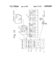
- FIG. 1 is a system diagram of a first embodiment of an image data processing system in accordance with the present invention
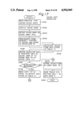
- FIG. 2 is a block diagram of the image data processing system shown in FIG. 1;
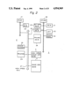
- FIG. 3 is a flow chart explaining the operation of the image data processing system shown in FIG. 1;
- FIG. 4 is a conceptual diagram explaining an area blocking and linkage realized in the image data processing system shown in FIG. 1;
- FIG. 5 is a view explaining a flow of picture data in the image data processing system shown in FIG. 1;
- FIG. 6 is a view explaining a mode of use of data in the image data processing system shown in FIG. 1;
- FIGS. 7a to 7c are views explaining the structure of the picture data and the management of the blocked areas, which are controlled in the image data processing system shown in FIG. 1;
- FIG. 8 is a view illustrating a reduction of mask data in FIG. 1;
- FIG. 9 is a diagram explaining a stack in the image information processing system shown in FIG. 1;
- FIG. 10 is a view of a display control key used for the stack in FIG. 9;
- FIGS. 11 and 12a to 12c are flow charts explaining the stack operation
- FIGS. 13 and 14 are diagrams explaining stacks modified as compared to the stack shown in FIG. 9;
- FIG. 15 is a diagram explaining a sound addition performed in the image information processing system shown in FIG. 1;
- FIG. 16 is a block diagram of the image information processing system which performs the sound addition
- FIG. 17 is a flow chart explaining a sound edit operation of FIG. 15;
- FIG. 18 is a flow chart explaining sound reproduction
- FIG. 19 is a diagram explaining a linkage which is performed in the image information processing system shown in FIG. 1;
- FIG. 20 is a flow chart representing a linkage definition
- FIG. 21 is a flow chart representing a linkage data display
- FIG. 22 is a diagram illustrating the operation when using a portable key.
- FIG. 23 is a block diagram of an image information processing system connected to the portable key shown in FIG. 22.
- FIG. 1 is a system diagram of a first embodiment of an image data (information) processing system in accordance with the present invention.
- the image data processing system 1 includes an input data processing portion 2, an image data-base portion 4, a high-speed image data-base portion 5, and an output data processing portion 3.
- the image data processing system 1 utilizes an easily usable image data-base in the image data-base portion 4, and outputs easily handleable image data in connection with a plurality of image data at a high-speed from the high-speed image data-base portion 5.
- the input data processing portion 2 inputs image information, such as character data, picture data, and sound (audio) data, converts the input image information to data usable for an "intelligent environment support", and adjusts, connects and/or combines the image information to produce new intelligent information data, for example, data combined with the input data.
- the output data processing portion 3 outputs high speed image information in a desired form, provides an improved interactive image man-machine-interface, and rearranges and re-inputs the output image information.
- image information or "image data” involves all information such as picture data, character data, and sound (audio) data.
- FIG. 2 is a block diagram of the image information processing system shown in FIG. 1.
- reference 21 denotes a central processor unit (CPU) for controlling the entire image information processing system
- 22 a control memory storing control programs for controlling the entire image information processing system
- 23 an image scanner for reading image information
- 24 an image printer for printing out the image information
- 27 a high-speed bus for transferring a large amount of image data at a high speed.
- the above components form the input data processing portion 2.
- Reference 28 denotes another CPU for controlling a display system forming the output data processing portion 3, 29 a bit map memory for processing the image information bit-by-bit, 30 a video memory for storing data to be displayed on a CRT 32, 31 a memory used for the CPU 28, and 33 a touch panel mounted on the CRT 32 and used for inputting position data by touching a finger thereto.
- Reference 34 denotes a frame memory for storing the image information from the image data-base portion 4, and outputting a desired frame image data to the video memory 30 when a display is requested.
- the image data-base portion 4 can be realized by an optical disc memory system.
- the high-speed image data-base portion 5 functions as a frame file memory.
- Each image data 6, 10, 11, and 12 shown in FIG. 4 is read by the image scanner 23 of FIG. 2 and stored in the image data-base portion 4 as image data 8-1 forming a picture information 7 (steps S001 and S002 in FIG. 3). Also, the image data is transferred to the video memory 30 through the high-speed bus 27 and displayed on the CRT 32 (S003).
- a user encloses image information blocks on the CRT 32 as shown by, for example, blocks 9-1 and 9-2 through the touch panel 33 of FIG. 2, and defines areas of the image information. This operation is defined as "area blocking".
- control data 8-3 is produced.
- the control data 8-3 also forms a part of the picture data 7 and is used for controlling the image data 8-1 and the mask data 8-2.
- the control data 8-3 concerning the image data may include the following items:
- control data concerning the blocked area may include the following items:
- category (or classification) data such as texts, charts, characters, drawings in the blocked area
- a link can be made as shown in FIG. 4, i.e., between the area 9-1 in the image data 6 and the image data 11; between the area 9-2 in the image data 6 and the area 9-3 in the image data 10, and between the image data 6 and the image data 12, etc.
- the linkage data is stored in the control data 8-3.
- the link can be applied as follows: when the image data 6 is displayed on the CRT 32 and the user touches the area 9-1, the linked image data 11 can be displayed on the CRT 32 as a next display. When the user touches the area 9-2 while displaying the image data 6, the linked image data 10 can be displayed and the area 9-3 can be flickered. When the user touches an area outside of the areas 9-1 and 9-2 while displaying the image data 6, the linked image data 12 can be displayed.
- the linkage area 9-1 is called source linked data, and the image data 11 is called depended linked data. Also, the linkage area 9-2 is called source linked data, and the area 9-3 is called depended linked data, and so on.
- a stack can be made.
- the stack will be described later with reference to a specific example.
- the user can access the picture data 7 in a variety of modes. This access will be described later.
- FIG. 5 shows a flow of the picture data.
- MAIN DISPLAY corresponds to the CRT 32 of FIG. 2.
- PICTURE DATA shows a plurality of the picture data 7 which are linked and integrated with each other and are displayed on the CRT 32.
- a SUB DISPLAY is located on a control panel which will be described later with reference to FIG. 22.
- the SUB DISPLAY controls the image information processing system 1 of FIG. 1 and is used for displaying control guidance by characters.
- a KEY is also provided on the control panel.
- a DISPLAY STACK and a SLEEP STACK can be stored in the frame memory 34 of FIG. 2.
- the DISPLAY STACK and the SLEEP STACK are temporarily stored for various image processings.
- FIG. 6 shows a mode of use of the data in the image data processing system 1.
- An image data 101 is produced by the image scanner 23 of FIG. 2.
- the image data 101 can be subjected to an image transform, such as rotation, enlargement, reduction, etc. Sound information can be added to the image data 101 by a picturing process 102, producing picture data 103.
- the picture data 7 of FIG. 4 can be linked as set forth at step S006 by a filing step 104.
- the linked picture data is stored as an electronic file 105.
- contents in the electronic file 105 and the picture data 103 are used to produce a programmed picture information 107 applicable to respective requirements.
- the programmed picture information 107 can be displayed on the MAIN DISPLAY in FIG. 5, i.e., on the CRT 32.
- FIGS. 7a to 7c show image data to be blocked, a relationship among an image data 8-1, a mask data 8-2, and a control data 8-3, and a management of the blocked areas.
- four mask plane MP 1 , MP 2 , MP 4 and MP 8 are provided and correspond to the following bits:
- AREA 9 is specified by designating bit data of "1001".
- the mask plane can be compressed as shown in FIG. 8.
- the image data has a capacity of m bits ⁇ n bits, and the mask plane is reduced to a size of j bits ⁇ k bits where j ⁇ n and k ⁇ n.
- the original resolution of the image data, per se, should be maintained, since the mask plane can be reduced without an adverse affect on the resolution of the image processing.
- reference 51 indicates a display data storage portion
- 52 and 53 are picture data groups to be displayed
- 54 an image data being stored in the video memory 30 of FIG. 2 and displayed on the CRT 32
- 55 a stack
- 57 is tag data.
- the display data storage portion 51 and the stack 55 occupy a part of the frame memory 34 of FIG. 2.
- Data transfer between the display data storage portion 51 and the video memory 30, and between the stack 55 and the video memory 30, can be carried out through the high-speed bus 27 shown in FIG. 2.
- FIG. 10 shows display control keys 150.
- the display control keys 150 include a push-down key 110, a pop-up key 111, page feed keys 112 and 113, a set key 114 used for tag control, a reset key 115 used for the tag control, a search designation key 116 used for the tag control, and a mode control key 117.
- the picture data are previously programmed and grouped in a sequence of A, . . . , J, K, L, M, N, O, . . . , X, and stored in the display data storage portion 51 as the picture data groups to be displayed.
- the picture data group L is transferred to the video memory 30 and displayed on the CRT 30. If the left-side page feed key 112 is operated (S011), the picture data group L is removed (S013) from the video memory 30, but still remains in the display data storage 51 as a neighbour of a next picture data group K.
- the picture data group M is then transferred (S014) to the video memory 30 and displayed on the CRT 32.
- the picture data groups can be consecutively paged through the CRT 32. Similarly, a page feed in the opposite direction can be effected by operating (S013) the right-side page feed key 113.
- the CPU 21 controls the above operation. The entire page shift operation is shown in FIG. 11.
- a stack function is provided.
- the stack 55 is constructed in the frame memory 34, and address management is achieved by the CPU 21. If the push-down key 110 is operated (S021), the picture data group displayed on the CRT 32 and stored in the video memory 30 is transferred (S022) to the stack 55 in the frame memory 34 through the high-speed bus 27. If the pop-up key 111 is operated (S025), the data in the stack 55 is transferred (S026) to the video memory 30 through the high-speed bus 27.
- Tag data 57 can be added (S024 or S034) to the stacked picture data group in the stack 55 by operating (S023 or S033) the set key 114.
- a tagged and stacked picture data group can be found and displayed (S044) by operating (S045) the search key 116.
- the tag 57 can be removed (S036) from the tagged picture data group by operating (S035) the reset key 115.
- the mode control key 117 is placed at the STACK position, the stacked picture data groups can be displayed on the CRT 32 in response to the operation of the page feed key 112 or 113.
- the mode control key 117 is placed at the DATA position, the picture data groups in the display (S048) data storage portion 51 can be displayed in response to the operation of the page feed key 112 or 113.
- the entire stack operation is shown in detail in FIGS. 12a to 12c.
- FIG. 13 shows an improved structure for processing the stack.
- a stack set 60 consisting of a virtual stack 60a and a secondary storage file 60b is added to the stack structure shown in FIG. 9. Stacked picture data can be transferred between the stack set 60 and the stack 55.
- the provision of the stack set 60 enables an additional stack to be obtained in response to a request during a sequential display of the image data.
- the display data storage portion 51 and the stack 55 occupy portions in the frame memory 34 of FIG. 2.
- the virtual stack 60a also occupies a portion in the frame memory 34, but the secondary storage file 60b occupies a portion in the high-speed image data-base portion 4 of FIG. 2.
- the stack set 60 stores stack data removed from the stack 55 and frequently reused.
- the designation for storing this data is effected by the user.
- the virtual stack 60a can hold several pieces of this data.
- the secondary storage file 60b can hold a large amount of this data. If display of this data is required, the data stored in the virtual stack 60a, if any, is promptly used as the stack data. When that data is stored in the secondary storage file 60b, that data is transferred to the frame memory 34 and used as the stack data.
- FIG. 14 An additional virtual stack 60a' which occupies a part of push-down frame memory 34 is provided.
- the virtual stack 60a stores the stack data concerning the push-down; the virtual stack 60a' stores pop-up stack data; and the secondary storage file 60b is commonly used.
- a sound-added image data processing will be described with reference to FIGS. 15 and 16.
- sound data can be added together with areas 9-11 and 9-12.
- a sound data table 10 is included in the control data 8-3. Sound data 11-1 and 11-2 are added as a part of the picture data 7.
- a sound mark number column (SOUND MARK NO.) designates numbers of the sound data 11-1 and 11-2
- a sound mark position column (SOUND MARK POS.) indicates positions at which a sound mark is displayed in the areas 9-11 and 9-12 on the CRT 32
- a sound information address column SOUND INF.
- ADD. indicates addresses stored in the sound data 11-1 and 11-2
- a protection identification column indicates protection codes (inhibition) to inhibit an output for sound of identified areas
- a sound time column represents times at which sound is output.
- Reference 13 denotes a handset for the input and output of sound.
- the user designates the area 9-12 through the touch panel 33 and inputs sound through the handset 13.
- the sound data 11-2 and the sound data table 10 are generated in accordance with the input sound. Thereafter, when the image data is displayed, the sound mark(s) is also displayed in a corresponding area together with the image data. If the user designates the area by touch, the corresponding sound is output through the handset 13 in accordance with the generated sound data 11-2 and the sound data table 10.
- the image processing system further includes a sound memory 37 and an analog-to-digital and digital-to-analog converter (ADC/DAC) 38 connected to the hand-set 13 having a microphone and a speaker.
- the memory 31 includes a sound edit program for inputting sound and generating the sound data table 10.
- the user starts the sound edit program stored in the memory 31.
- the sound edit program in the CPU 28 outputs a message for inputting sound mark position where the data sound data is added, and the user designates the position by touching a finger to the position on the touch panel 33.
- the sound edit program reads the corresponding position data and transfers a corresponding sound mark signal from the bit map memory 29 to an area in the video memory 30 corresponding to the read position through a raster operation.
- the sound edit program displays a sound mark at the designated point on the CRT 32. This means that a recording of the sound is in a read state.
- the sound edit program defines the sound mark number and the sound mark position in the table 10.
- the user inputs a sound to be stored through the hand set 13.
- the input sound is converted to digital at the ADC/DAC 38 and stored in the sound memory 37 as the sound data.
- the sound edit program calculates a sound time by using the timer 35 and stores that time in the table 10.
- the sound edit program defines the sound information address and saves that address in the table 10.
- the sound edit program transfers the data in the sound memory 37 to the frame memory 34 as the sound data 11-1 in the picture data 7.
- the sound edit program displays an inquiry to determine whether or not an identification (ID) protection code for the recorded sound is needed. If requiring the ID protection, the user inputs an ID protection code through the ID card reader keyboard 36. The sound edit program reads the ID protection code and stores that code in the table 10.
- ID identification
- the sound edit program reads the ID protection code and stores that code in the table 10.
- the sound edit program stores the sound time calculated at step S055 in the video memory 30, and displays the sound time on the CRT 32.
- the obtained table 10 and the picture data 7 including the sound data 11-1 are stored in the image data-base portion 5.
- a sound reproduction program stored in the memory 31 and executed by the CPU 28 reads the display request through the ID card reader 36.
- the sound reproduction program then transfers the picture data 7 and the table 10 from the image data-base portion 5 to the frame memory 34.
- the sound reproduction program further transfers the picture data transferred in the frame memory 34 to the video memory 30 in response to the display request from the read ID card.
- the sound reproduction program compares the ID code from the ID card with the ID protection code stored in the table 10, deletes the sound mark signal in the video memory 30 to eliminate the sound mark on the CRT 32 and to inhibits access to the display when coinciding.
- the sound mark is displayed on the CRT 32 together with other data. This indicates that the user can access the sound mark.
- the user touches the position where the sound mark is displayed.
- the sound reproduction program reads the touched position and verifies the validity of the position designation.
- the sound reproduction program confirms the availability of the reproduction, and then transfers a corresponding sound data 11-1 stored in the frame memory to the sound memory 37 through the high speed bus 27.
- the data stored in the sound memory 37 is converted to analog at the ADC/DAC 38 and output as sound through a speaker in the handset 13.
- the sound reproduction program counts down the sound timer in the video memory to display a remaining sound time.
- the sound reproduction program starts to flicker the sound mark in the display.
- steps S076 to S079 are repeated until the sound timer count reaches zero.
- the sound reproduction program stops the flicker of the sound mark.
- FIG. 19 shows a plurality of image data groups 6a to 6f.
- Each image data group for example, 6a, consists of a plurality of image data 6a-1 to 6a-n. Also, a plurality of picture data exists corresponding to each image data group. In FIG. 19, only the picture data 7a corresponding to the image data group 6a is shown.
- Each image group, for example, 6a is previously area blocked as areas 9a-1 and 9a-2. The image data groups and the blocked areas are then linked together.
- the linkage is classified into two parts: a link between each image data group, for example, between the image data 6a-1 and 6a-2, and a link between the image data groups, for example, between the image data 6a-1 and the image data 6d-1 or between the area 9a-2 and the area 9b-1.
- the former is called “vertical direction linkage”
- the latter is called “lateral direction linkage”.
- the control data for example, 8a-3, further includes an address storage portion for storing addresses of the vertical direction linkage and of the lateral direction linkage.
- the linkage can be used for supplying supplemental information to the user in addition to the data which is being displayed. For example, when the image data 6a-1 is displayed, the data of area 9b-1, which is linked as a dependent data to the area 9a-2, can be displayed.
- the linked dependent data can be defined as secret data, and this secret data can be accessed only by authorized users.
- FIG. 20 shows a linkage definition operation. After the data input processing and the "area blocking" the linkage definition is carried out by reading (S091, S092 and S097) source image data or source area, a dependent image data or a dependent area, to be linked and a secret information code if required, through the ID card reader 36. The linkage definition is carried out by the linkage definition program.
- FIG. 21 shows a linkage data display operation.
- the linked data display of, for example 6e-1 FIG. 19, can be carried out during display of the source data, for example, 6a-1.
- a linked data display program reads the position on the touch panel (S102).
- the linked data program checks the validity of the input data. If the linkage is not defined, the linked data display program is terminated (S103). If the linkage is valid, the linked data display program further checked whether or not a secret dependency exists (S104). If the secret dependency exists, the linked data display program reads a code from the keyboard and checks whether or not it is legal (S105). If the code is illegal, the linked data display is not effected. If the code is legal, the linked data of the area 9b-1 is displayed (S106).
- a linked data display for the image data 6e-1 can be carried out.
- a portable key unit 160 is provided as shown in FIGS. 22 and 23.
- the portable key unit 160 includes a sub display portion 161 composed of a Liquid Crystal Display (LCD) and an input key unit portion 165.
- the portable key 160 is connected to the CPU 28, FIGS. 2 and 16.
- the sub display portion 161 can be used as the SUB DISPLAY shown in FIG. 5. Also, the input key portion 165 can be used as the KEY shown in FIG. 5.
- the display portion 161 can display words such as "NEXT DISPLAY", “SPEAK”, “RETURN”, “HELP”.
- the input key portion 165 includes a designation key 165a, a mode key portion 165b, a ten key portion 165c and a control key portion 165d.
- the designation key 165a can be used for designating a command corresponding to a message displayed on the display portion 161.
- the mode key portion 165b includes mode change keys such as "STACK/DATA", shown in FIG. 10, and "LINKAGE” for linking the image data as described above.
- the ten key portion 165c can be used for designating the linkage area or image data, and inputting the secret code, etc.
- the control key portion 165d includes the "PAGE FEED” keys shown in FIG. 10, the "PUSH-DOWN” key, the "POP-UP” key, the "TAG CONTROL” key, etc.
- the display portion 161 of the portable key unit 160 provides the user with messages for operating the image processing system in a simple form.
- the input key portion 165 includes a variety of keys necessary for easily operating the image processing system or designating various information, except for directly designating the position on the CRT by the touch panel.
- the provision of the portable key unit 160 together with the touch panel provides good man-machine communication, and the CRT 32 can be used for this man-machine-communication.
- the highly compressed image data can be coded by, for example, MH coding and M 2 R coding, both defined by CCITT.
- the MH/M 2 R coding provides a high data compression, for example, approximately 1/10 to 1/20. But the MH/M 2 R coding needs a long coding time, for example, approximately 1 sec for compressing the image data on a sheet of 210 mm ⁇ 297 mm.
- the high-speed compressable image data can be coded by, for example, King Fisher fix length compression coding (KF coding).
- KF coding provides a medium data compression, for example, approximately 1/5.
- the KF coding can code the image data at a considerably high speed, for example, 35 msec for compressing the image data on a sheet 210 mm ⁇ 297 mm.
- the KF coding will be briefly described.
- the KF coding processes an original data for every byte of data (eight bit data) and expresses the byte data by a byte status (BS) of two bits, as shown in Table 2.
- BS byte status
- the data which is input and processed by, for example, rotation or filtering, at the data input processing portion 2 is highly compressed and stored in the image data-base portion 4.
- the data stored in the image data-base portion 4, which is needed for the response to the user requests, is converted into high-speed compressable image data and transferred to the high-speed image data-base portion 5.
- the data transferred in the high-speed image data-base portion 5 and needed for an output in response to a user request, and having a capacity of one frame for display is converted to a non-compressed image data and stored in the frame memory 34.
- the data transferred to the frame memory 34 is then transferred to the video memory 30 and displayed on the CRT 32.
- the above data transfers are carried out through the high speed bus 27.
- the frame memory 34 can be realized by a static RAM, or a dynamic RAM, or the like.
- the high-speed image data-base portion 5 can be realized by a magnetic disc system.
- the image data-base portion 4 can be realized by an optical disc memory system.
- the optical memory system can be a read-only-type, a write-once-type and/or a readable and writable-type, such as an optical magnetic disc memory system.
Abstract
Description
              TABLE A
______________________________________
BIT         MASK PLANE
______________________________________
0 (2.sup.0) MP.sub.1
1 (2.sup.1) MP.sub.2
2 (2.sup.2) MP.sub.4
3 (2.sup.3) MP.sub.8
______________________________________
                                  TABLE 1
__________________________________________________________________________
                   HIGH-SPEED  IMAGE
       FRAME MEMORY
                   IMAGE DATA-BASE
                               DATA-BASE
__________________________________________________________________________
SPEED  FAST        MIDDLE      LOW
CAPACITY
       SMALL       MIDDLE      LARGE
       (FRAME SIZE)
IMAGE  NON-COMPRESSED
                   HIGH-SPEED  HIGHLY
DATA   IMAGE DATA FOR
                   COMPRESSABLE
                               COMPRESSED
FORMAT CURRENT USE IMAGE DATA  IMAGE DATA
__________________________________________________________________________
              TABLE 2
______________________________________
BS            CONTENT
______________________________________
00            all white
10            all black
01            mixed with white and black
11            control code
______________________________________
              TABLE 3
______________________________________
ORIGINAL DATA
             00000000 11111111 00000000
                                      01100101
BS           00       10       00     01
IB                                    01100101
KF CODED DATA
             00100001,
                      01100101
______________________________________
Claims (32)
Applications Claiming Priority (18)
| Application Number | Priority Date | Filing Date | Title |
|---|---|---|---|
| JP61-303471 | 1986-12-19 | ||
| JP30347186A JPS63156287A (en) | 1986-12-19 | 1986-12-19 | Image processing processor |
| JP61313155A JPH0786916B2 (en) | 1986-12-26 | 1986-12-26 | Image processing processor |
| JP313160160 | 1986-12-26 | ||
| JP61-313157 | 1986-12-26 | ||
| JP61313157A JPH0786917B2 (en) | 1986-12-26 | 1986-12-26 | Image processing processor with audio |
| JP61313160A JPH0782552B2 (en) | 1986-12-26 | 1986-12-26 | Image processing processor |
| JP61313159A JPH0786918B2 (en) | 1986-12-26 | 1986-12-26 | Image processing device |
| JP313161161 | 1986-12-26 | ||
| JP313162162 | 1986-12-26 | ||
| JP31315686A JPH0833930B2 (en) | 1986-12-26 | 1986-12-26 | Image processing processor with stack function |
| JP61313161A JPH0782553B2 (en) | 1986-12-26 | 1986-12-26 | Image high-speed processing device |
| JP61-313158 | 1986-12-26 | ||
| JP61-313156 | 1986-12-26 | ||
| JP313159159 | 1986-12-26 | ||
| JP31316286A JPH0833931B2 (en) | 1986-12-26 | 1986-12-26 | Image processing processor with stack function |
| JP61313158A JPH0833918B2 (en) | 1986-12-26 | 1986-12-26 | Programmed picture flow processor |
| JP61-313155 | 1986-12-26 |
Publications (1)
| Publication Number | Publication Date |
|---|---|
| US4954969A true US4954969A (en) | 1990-09-04 |
Family
ID=27577740
Family Applications (1)
| Application Number | Title | Priority Date | Filing Date |
|---|---|---|---|
| US07/134,972 Expired - Lifetime US4954969A (en) | 1986-12-19 | 1987-12-18 | System for processing various types of information in easily usable form |
Country Status (4)
| Country | Link |
|---|---|
| US (1) | US4954969A (en) |
| EP (1) | EP0272886A3 (en) |
| AU (1) | AU592914B2 (en) |
| CA (1) | CA1315391C (en) |
Cited By (53)
| Publication number | Priority date | Publication date | Assignee | Title |
|---|---|---|---|---|
| US5254979A (en) * | 1988-03-12 | 1993-10-19 | Dupont Pixel Systems Limited | Raster operations |
| US5297253A (en) * | 1992-01-09 | 1994-03-22 | Ehrlich Associates, Inc. | Computer user interface navigational tool |
| US5302132A (en) * | 1992-04-01 | 1994-04-12 | Corder Paul R | Instructional system and method for improving communication skills |
| WO1995010813A1 (en) * | 1993-10-15 | 1995-04-20 | Irving Tsai | Method for enabling printed documents to retain electronic links to electronic reference information |
| US5412774A (en) * | 1990-08-29 | 1995-05-02 | At&T Corp. | Apparatus for and method of displaying a data item of a database using the display function of a selected data item |
| US5428727A (en) * | 1989-01-27 | 1995-06-27 | Kurosu; Yasuo | Method and system for registering and filing image data |
| US5434590A (en) * | 1990-12-11 | 1995-07-18 | International Business Machines Corporation | Multimedia system |
| US5448257A (en) * | 1991-07-18 | 1995-09-05 | Chips And Technologies, Inc. | Frame buffer with matched frame rate |
| US5469539A (en) * | 1992-09-18 | 1995-11-21 | Hitachi Software Engineering Co., Ltd. | Method for abstracting/detailing structuring elements of system specification information |
| US5499921A (en) * | 1992-09-30 | 1996-03-19 | Yamaha Corporation | Karaoke apparatus with visual assistance in physical vocalism |
| US5526479A (en) * | 1990-06-25 | 1996-06-11 | Barstow; David | Method and apparatus for broadcasting live events to another location and producing a computer simulation of the events at that location |
| US5526480A (en) * | 1992-12-28 | 1996-06-11 | International Business Machines Corporation | Time domain scroll bar for multimedia presentations in a data processing system |
| US5526520A (en) * | 1993-09-21 | 1996-06-11 | Krause; Gary M. | Method to organize and manipulate blueprint documents using hypermedia links from a primary document to recall related secondary documents |
| US5533903A (en) * | 1994-06-06 | 1996-07-09 | Kennedy; Stephen E. | Method and system for music training |
| US5537530A (en) * | 1992-08-12 | 1996-07-16 | International Business Machines Corporation | Video editing by locating segment boundaries and reordering segment sequences |
| US5539869A (en) * | 1992-09-28 | 1996-07-23 | Ford Motor Company | Method and system for processing and presenting on-line, multimedia information in a tree structure |
| US5577208A (en) * | 1991-06-25 | 1996-11-19 | Alcatel Nv | "Multimedia" intercommunication between workstations having auxiliary unit directly connected to output of workstation and input to display wherein local and remote image data are combined |
| US5584006A (en) * | 1989-12-22 | 1996-12-10 | Avid Technology, Inc. | Media storage and retrieval system including determination of media data associated with requests based on source identifiers and ranges within the media data |
| US5657248A (en) * | 1994-06-10 | 1997-08-12 | Hitachi, Ltd. | Image display apparatus |
| US5690496A (en) * | 1994-06-06 | 1997-11-25 | Red Ant, Inc. | Multimedia product for use in a computer for music instruction and use |
| US5692906A (en) * | 1992-04-01 | 1997-12-02 | Corder; Paul R. | Method of diagnosing and remediating a deficiency in communications skills |
| US5697789A (en) * | 1994-11-22 | 1997-12-16 | Softrade International, Inc. | Method and system for aiding foreign language instruction |
| US5714985A (en) * | 1988-07-29 | 1998-02-03 | Canon Kabushiki Kaisha | Image processing system capable of high-speed and high-resolution image synthesis |
| US5715445A (en) * | 1994-09-02 | 1998-02-03 | Wolfe; Mark A. | Document retrieval system employing a preloading procedure |
| US5724605A (en) * | 1992-04-10 | 1998-03-03 | Avid Technology, Inc. | Method and apparatus for representing and editing multimedia compositions using a tree structure |
| US5810599A (en) * | 1994-01-26 | 1998-09-22 | E-Systems, Inc. | Interactive audio-visual foreign language skills maintenance system and method |
| US5838458A (en) * | 1992-02-25 | 1998-11-17 | Tsai; Irving | Method and apparatus for linking designated portions of a received document image with an electronic address |
| US5870770A (en) * | 1995-06-07 | 1999-02-09 | Wolfe; Mark A. | Document research system and method for displaying citing documents |
| US6018337A (en) * | 1992-04-10 | 2000-01-25 | Avid Technology, Inc. | Media composer including pointer-based display of sequentially stored samples |
| US6084569A (en) * | 1994-03-18 | 2000-07-04 | Avid Technology, Inc. | Editing interface |
| US6186794B1 (en) * | 1993-04-02 | 2001-02-13 | Breakthrough To Literacy, Inc. | Apparatus for interactive adaptive learning by an individual through at least one of a stimuli presentation device and a user perceivable display |
| US6249275B1 (en) * | 1996-02-01 | 2001-06-19 | Seiko Epson Corporation | Portable information gathering apparatus and information gathering method performed thereby |
| US6292813B1 (en) | 1997-11-17 | 2001-09-18 | Mark A. Wolfe | System and method for communicating information relating to a network resource |
| US6336131B1 (en) | 1996-10-08 | 2002-01-01 | Mark A. Wolfe | System and method for communicating information relating to a network resource |
| US6342894B1 (en) * | 1991-03-22 | 2002-01-29 | Canon Kabushiki Kaisha | Icon display method |
| US6417844B1 (en) * | 1996-06-25 | 2002-07-09 | Seiko Epson Corporation | Data processing apparatus and data processing method |
| US6604103B1 (en) | 1994-09-02 | 2003-08-05 | Mark A. Wolfe | System and method for information retrieval employing a preloading procedure |
| US6632250B1 (en) | 1998-09-11 | 2003-10-14 | Datacard Corporation | Method and system for creating a card |
| US6678864B1 (en) | 1992-02-25 | 2004-01-13 | Irving Tsai | Method and apparatus for linking designated portions of a received document image with an electronic address |
| US20040023191A1 (en) * | 2001-03-02 | 2004-02-05 | Brown Carolyn J. | Adaptive instructional process and system to facilitate oral and written language comprehension |
| US20040109946A1 (en) * | 2000-03-06 | 2004-06-10 | Prince Kendall W. | Method and apparatus for extruding a coating upon a substrate surface |
| US20040153751A1 (en) * | 1997-06-20 | 2004-08-05 | Nikon Corporation | Data processing apparatus |
| US20040199507A1 (en) * | 2003-04-04 | 2004-10-07 | Roger Tawa | Indexing media files in a distributed, multi-user system for managing and editing digital media |
| US7103594B1 (en) | 1994-09-02 | 2006-09-05 | Wolfe Mark A | System and method for information retrieval employing a preloading procedure |
| US20060279561A1 (en) * | 2005-04-19 | 2006-12-14 | Semiconductor Energy Laboratory Co., Ltd. | Display device |
| US7257604B1 (en) | 1997-11-17 | 2007-08-14 | Wolfe Mark A | System and method for communicating information relating to a network resource |
| US20070191690A1 (en) * | 2005-04-06 | 2007-08-16 | Mallinckrodt Inc. | Systems and methods for managing information relating to medical fluids and containers therefor |
| US7302638B1 (en) | 1995-06-07 | 2007-11-27 | Wolfe Mark A | Efficiently displaying and researching information about the interrelationships between documents |
| US20080033368A1 (en) * | 2006-04-04 | 2008-02-07 | Mallinckrodt Inc. | Systems and methods for managing information relating to medical fluids and containers therefor |
| US7373587B1 (en) | 1990-06-25 | 2008-05-13 | Barstow David R | Representing sub-events with physical exertion actions |
| US7386473B2 (en) | 1996-09-03 | 2008-06-10 | Nielsen Media Research, Inc. | Content display monitoring by a processing system |
| US8626763B1 (en) | 1997-05-22 | 2014-01-07 | Google Inc. | Server-side suggestion of preload operations |
| US8639694B1 (en) | 1994-09-02 | 2014-01-28 | Google Inc. | Client-side processing of preload operations |
Families Citing this family (3)
| Publication number | Priority date | Publication date | Assignee | Title |
|---|---|---|---|---|
| FR2645286B1 (en) * | 1989-03-29 | 1992-01-03 | Gen Electric Cgr | LIGHT RADIOGRAPHY TABLE |
| JPH0368283A (en) * | 1989-04-27 | 1991-03-25 | Digital Fx Inc | Method and apparatus for processing electronic image |
| CA2233340C (en) * | 1995-09-28 | 2002-08-06 | Nina J. Kuch | Multi-media technology for nutrition education and diet planning |
Citations (5)
| Publication number | Priority date | Publication date | Assignee | Title |
|---|---|---|---|---|
| US4484302A (en) * | 1980-11-20 | 1984-11-20 | International Business Machines Corporation | Single screen display system with multiple virtual display having prioritized service programs and dedicated memory stacks |
| US4567480A (en) * | 1982-12-13 | 1986-01-28 | John Fluke Mfg. Co., Inc. | Touch-sensitive overlay |
| US4569019A (en) * | 1983-06-03 | 1986-02-04 | Commodore Business Machines Inc. | Video sound and system control circuit |
| US4755810A (en) * | 1985-04-05 | 1988-07-05 | Tektronix, Inc. | Frame buffer memory |
| US4775858A (en) * | 1984-10-10 | 1988-10-04 | Quantel Limited | Video image creation |
Family Cites Families (5)
| Publication number | Priority date | Publication date | Assignee | Title |
|---|---|---|---|---|
| GB1551229A (en) * | 1976-04-02 | 1979-08-30 | Univ Manchester | Image analysing systems |
| JPS5776652A (en) * | 1980-10-31 | 1982-05-13 | Toshiba Corp | Display system for picture information |
| US4673988A (en) * | 1985-04-22 | 1987-06-16 | E.I. Du Pont De Nemours And Company | Electronic mosaic imaging process |
| GB8515323D0 (en) * | 1985-06-17 | 1985-07-17 | Coats Viyella Plc | Retail trading systems |
| US4782388A (en) * | 1986-10-24 | 1988-11-01 | The Grass Valley Group, Inc. | Method and apparatus for providing video mosaic effects |
-
1987
- 1987-12-17 EP EP19870311149 patent/EP0272886A3/en not_active Withdrawn
- 1987-12-17 AU AU82678/87A patent/AU592914B2/en not_active Ceased
- 1987-12-18 US US07/134,972 patent/US4954969A/en not_active Expired - Lifetime
- 1987-12-18 CA CA000554754A patent/CA1315391C/en not_active Expired - Fee Related
Patent Citations (5)
| Publication number | Priority date | Publication date | Assignee | Title |
|---|---|---|---|---|
| US4484302A (en) * | 1980-11-20 | 1984-11-20 | International Business Machines Corporation | Single screen display system with multiple virtual display having prioritized service programs and dedicated memory stacks |
| US4567480A (en) * | 1982-12-13 | 1986-01-28 | John Fluke Mfg. Co., Inc. | Touch-sensitive overlay |
| US4569019A (en) * | 1983-06-03 | 1986-02-04 | Commodore Business Machines Inc. | Video sound and system control circuit |
| US4775858A (en) * | 1984-10-10 | 1988-10-04 | Quantel Limited | Video image creation |
| US4755810A (en) * | 1985-04-05 | 1988-07-05 | Tektronix, Inc. | Frame buffer memory |
Cited By (105)
| Publication number | Priority date | Publication date | Assignee | Title |
|---|---|---|---|---|
| US5254979A (en) * | 1988-03-12 | 1993-10-19 | Dupont Pixel Systems Limited | Raster operations |
| US5714985A (en) * | 1988-07-29 | 1998-02-03 | Canon Kabushiki Kaisha | Image processing system capable of high-speed and high-resolution image synthesis |
| US5428727A (en) * | 1989-01-27 | 1995-06-27 | Kurosu; Yasuo | Method and system for registering and filing image data |
| US6061758A (en) * | 1989-12-22 | 2000-05-09 | Avid Technology, Inc. | System and method for managing storage and retrieval of media data including dynamic linkage of media data files to clips of the media data |
| US6636869B1 (en) | 1989-12-22 | 2003-10-21 | Avid Techhnology, Inc. | Method, system and computer program product for managing media data files and related source information |
| US5584006A (en) * | 1989-12-22 | 1996-12-10 | Avid Technology, Inc. | Media storage and retrieval system including determination of media data associated with requests based on source identifiers and ranges within the media data |
| US5671347A (en) * | 1990-06-25 | 1997-09-23 | Barstow; David R. | Method and apparatus for broadcasting live events to another location and producing a computer simulation of the events at that location |
| US6204862B1 (en) * | 1990-06-25 | 2001-03-20 | David R. Barstow | Method and apparatus for broadcasting live events to another location and producing a computer simulation of the events at that location |
| US7373587B1 (en) | 1990-06-25 | 2008-05-13 | Barstow David R | Representing sub-events with physical exertion actions |
| US20080209307A1 (en) * | 1990-06-25 | 2008-08-28 | Barstow David R | Representing sub-event with physical exertion actions |
| US5526479A (en) * | 1990-06-25 | 1996-06-11 | Barstow; David | Method and apparatus for broadcasting live events to another location and producing a computer simulation of the events at that location |
| US5412774A (en) * | 1990-08-29 | 1995-05-02 | At&T Corp. | Apparatus for and method of displaying a data item of a database using the display function of a selected data item |
| US5434590A (en) * | 1990-12-11 | 1995-07-18 | International Business Machines Corporation | Multimedia system |
| US6342894B1 (en) * | 1991-03-22 | 2002-01-29 | Canon Kabushiki Kaisha | Icon display method |
| US5577208A (en) * | 1991-06-25 | 1996-11-19 | Alcatel Nv | "Multimedia" intercommunication between workstations having auxiliary unit directly connected to output of workstation and input to display wherein local and remote image data are combined |
| US5448257A (en) * | 1991-07-18 | 1995-09-05 | Chips And Technologies, Inc. | Frame buffer with matched frame rate |
| US5297253A (en) * | 1992-01-09 | 1994-03-22 | Ehrlich Associates, Inc. | Computer user interface navigational tool |
| US5495581A (en) * | 1992-02-25 | 1996-02-27 | Tsai; Irving | Method and apparatus for linking a document with associated reference information using pattern matching |
| US6678864B1 (en) | 1992-02-25 | 2004-01-13 | Irving Tsai | Method and apparatus for linking designated portions of a received document image with an electronic address |
| US5838458A (en) * | 1992-02-25 | 1998-11-17 | Tsai; Irving | Method and apparatus for linking designated portions of a received document image with an electronic address |
| US5387104A (en) * | 1992-04-01 | 1995-02-07 | Corder; Paul R. | Instructional system for improving communication skills |
| US5692906A (en) * | 1992-04-01 | 1997-12-02 | Corder; Paul R. | Method of diagnosing and remediating a deficiency in communications skills |
| US5302132A (en) * | 1992-04-01 | 1994-04-12 | Corder Paul R | Instructional system and method for improving communication skills |
| US6018337A (en) * | 1992-04-10 | 2000-01-25 | Avid Technology, Inc. | Media composer including pointer-based display of sequentially stored samples |
| US5724605A (en) * | 1992-04-10 | 1998-03-03 | Avid Technology, Inc. | Method and apparatus for representing and editing multimedia compositions using a tree structure |
| US5537530A (en) * | 1992-08-12 | 1996-07-16 | International Business Machines Corporation | Video editing by locating segment boundaries and reordering segment sequences |
| US5469539A (en) * | 1992-09-18 | 1995-11-21 | Hitachi Software Engineering Co., Ltd. | Method for abstracting/detailing structuring elements of system specification information |
| US5539869A (en) * | 1992-09-28 | 1996-07-23 | Ford Motor Company | Method and system for processing and presenting on-line, multimedia information in a tree structure |
| US5499921A (en) * | 1992-09-30 | 1996-03-19 | Yamaha Corporation | Karaoke apparatus with visual assistance in physical vocalism |
| US5526480A (en) * | 1992-12-28 | 1996-06-11 | International Business Machines Corporation | Time domain scroll bar for multimedia presentations in a data processing system |
| US6186794B1 (en) * | 1993-04-02 | 2001-02-13 | Breakthrough To Literacy, Inc. | Apparatus for interactive adaptive learning by an individual through at least one of a stimuli presentation device and a user perceivable display |
| US6206700B1 (en) * | 1993-04-02 | 2001-03-27 | Breakthrough To Literacy, Inc. | Apparatus and method for interactive adaptive learning by an individual through at least one of a stimuli presentation device and a user perceivable display |
| US5526520A (en) * | 1993-09-21 | 1996-06-11 | Krause; Gary M. | Method to organize and manipulate blueprint documents using hypermedia links from a primary document to recall related secondary documents |
| WO1995010813A1 (en) * | 1993-10-15 | 1995-04-20 | Irving Tsai | Method for enabling printed documents to retain electronic links to electronic reference information |
| US5810599A (en) * | 1994-01-26 | 1998-09-22 | E-Systems, Inc. | Interactive audio-visual foreign language skills maintenance system and method |
| US6084569A (en) * | 1994-03-18 | 2000-07-04 | Avid Technology, Inc. | Editing interface |
| US6271829B1 (en) * | 1994-03-18 | 2001-08-07 | Avid Technology, Inc. | Editing interface |
| US5690496A (en) * | 1994-06-06 | 1997-11-25 | Red Ant, Inc. | Multimedia product for use in a computer for music instruction and use |
| US5533903A (en) * | 1994-06-06 | 1996-07-09 | Kennedy; Stephen E. | Method and system for music training |
| US5657248A (en) * | 1994-06-10 | 1997-08-12 | Hitachi, Ltd. | Image display apparatus |
| US6301576B1 (en) | 1994-09-02 | 2001-10-09 | Mark A. Wolfe | Document retrieval system for retrieval of a first search document and a last search document from database |
| US5715445A (en) * | 1994-09-02 | 1998-02-03 | Wolfe; Mark A. | Document retrieval system employing a preloading procedure |
| US6604103B1 (en) | 1994-09-02 | 2003-08-05 | Mark A. Wolfe | System and method for information retrieval employing a preloading procedure |
| US7103594B1 (en) | 1994-09-02 | 2006-09-05 | Wolfe Mark A | System and method for information retrieval employing a preloading procedure |
| US8639694B1 (en) | 1994-09-02 | 2014-01-28 | Google Inc. | Client-side processing of preload operations |
| US5697789A (en) * | 1994-11-22 | 1997-12-16 | Softrade International, Inc. | Method and system for aiding foreign language instruction |
| US5882202A (en) * | 1994-11-22 | 1999-03-16 | Softrade International | Method and system for aiding foreign language instruction |
| US7302638B1 (en) | 1995-06-07 | 2007-11-27 | Wolfe Mark A | Efficiently displaying and researching information about the interrelationships between documents |
| US5870770A (en) * | 1995-06-07 | 1999-02-09 | Wolfe; Mark A. | Document research system and method for displaying citing documents |
| US6249275B1 (en) * | 1996-02-01 | 2001-06-19 | Seiko Epson Corporation | Portable information gathering apparatus and information gathering method performed thereby |
| US6417844B1 (en) * | 1996-06-25 | 2002-07-09 | Seiko Epson Corporation | Data processing apparatus and data processing method |
| US7720964B2 (en) | 1996-09-03 | 2010-05-18 | The Nielsen Company (Us), Llc | Content display monitor |
| US7653724B2 (en) | 1996-09-03 | 2010-01-26 | The Nielsen Company (Us), Llc. | Content display monitor |
| US7386473B2 (en) | 1996-09-03 | 2008-06-10 | Nielsen Media Research, Inc. | Content display monitoring by a processing system |
| US8719698B2 (en) | 1996-09-03 | 2014-05-06 | Comscore, Inc. | Content display monitor |
| US7590568B2 (en) | 1996-09-03 | 2009-09-15 | The Nielsen Company (Us), Llc | Content display monitor |
| US7756974B2 (en) | 1996-09-03 | 2010-07-13 | The Nielsen Company (Us), Llc. | Content display monitor |
| US7720963B2 (en) | 1996-09-03 | 2010-05-18 | The Nielsen Company (Us), Llc | Content display monitor |
| US8769394B2 (en) | 1996-09-03 | 2014-07-01 | Comscore, Inc. | Content display monitor |
| US7716326B2 (en) | 1996-09-03 | 2010-05-11 | The Nielsen Company (Us), Llc. | Content display monitor |
| US8713428B2 (en) | 1996-09-03 | 2014-04-29 | Comscore, Inc. | Content display monitor |
| US7650407B2 (en) | 1996-09-03 | 2010-01-19 | The Nielsen Company (Us), Llc. | Content display monitor |
| US7644156B2 (en) | 1996-09-03 | 2010-01-05 | The Nielsen Company(US), LLC. | Content display monitor |
| US7613635B2 (en) | 1996-09-03 | 2009-11-03 | The Nielsen Company (Us), Llc | Content display monitor |
| US6336131B1 (en) | 1996-10-08 | 2002-01-01 | Mark A. Wolfe | System and method for communicating information relating to a network resource |
| US7043526B1 (en) | 1996-10-08 | 2006-05-09 | Wolfe Mark A | System and method for communicating information relating to a network resource |
| US8849982B2 (en) | 1996-10-08 | 2014-09-30 | Google, Inc. | Communicating information relating to a network resource |
| US8626763B1 (en) | 1997-05-22 | 2014-01-07 | Google Inc. | Server-side suggestion of preload operations |
| US20040153751A1 (en) * | 1997-06-20 | 2004-08-05 | Nikon Corporation | Data processing apparatus |
| US7257604B1 (en) | 1997-11-17 | 2007-08-14 | Wolfe Mark A | System and method for communicating information relating to a network resource |
| US9934516B1 (en) | 1997-11-17 | 2018-04-03 | Google Llc | Communicating information relating to a network resource |
| US6292813B1 (en) | 1997-11-17 | 2001-09-18 | Mark A. Wolfe | System and method for communicating information relating to a network resource |
| US6632250B1 (en) | 1998-09-11 | 2003-10-14 | Datacard Corporation | Method and system for creating a card |
| US20040109946A1 (en) * | 2000-03-06 | 2004-06-10 | Prince Kendall W. | Method and apparatus for extruding a coating upon a substrate surface |
| US20040023191A1 (en) * | 2001-03-02 | 2004-02-05 | Brown Carolyn J. | Adaptive instructional process and system to facilitate oral and written language comprehension |
| US20040199507A1 (en) * | 2003-04-04 | 2004-10-07 | Roger Tawa | Indexing media files in a distributed, multi-user system for managing and editing digital media |
| US8001088B2 (en) | 2003-04-04 | 2011-08-16 | Avid Technology, Inc. | Indexing media files in a distributed, multi-user system for managing and editing digital media |
| US20070191690A1 (en) * | 2005-04-06 | 2007-08-16 | Mallinckrodt Inc. | Systems and methods for managing information relating to medical fluids and containers therefor |
| US7898416B2 (en) | 2005-04-06 | 2011-03-01 | Mallinckrodt Inc. | Systems and methods for managing information relating to medical fluids and containers therefor |
| US7588189B2 (en) | 2005-04-06 | 2009-09-15 | Mallinckrodt Inc. | Systems and methods for managing information relating to medical fluids and containers therefor |
| US20070229266A1 (en) * | 2005-04-06 | 2007-10-04 | Mallinckrodt Inc. | Systems and methods for managing information relating to medical fluids and containers therefor |
| US20070225672A1 (en) * | 2005-04-06 | 2007-09-27 | Mallinckrodt Inc. | Systems and methods for managing information relating to medical fluids and containers therefor |
| US20070208445A1 (en) * | 2005-04-06 | 2007-09-06 | Mallinckrodt Inc. | Systems and methods for managing information relating to medical fluids and containers therefor |
| US20070208308A1 (en) * | 2005-04-06 | 2007-09-06 | Mallinckrodt Inc. | Systems and methods for managing information relating to medical fluids and containers therefor |
| US7698180B2 (en) | 2005-04-06 | 2010-04-13 | Mallinckrodt Inc. | System for tracking data relating to radiopharmaceuticals and/or containers therefor |
| US20070197974A1 (en) * | 2005-04-06 | 2007-08-23 | Mallinckrodt Inc. | Systems and methods for managing information relating to medical fluids and containers therefor |
| US20070198297A1 (en) * | 2005-04-06 | 2007-08-23 | Mallinckrodt Inc. | Systems and methods for managing information relating to medical fluids and containers therefor |
| US20070250414A1 (en) * | 2005-04-06 | 2007-10-25 | Mallinckrodt Inc. | Systems and methods for managing information relating to medical fluids and containers therefor |
| US20080211674A1 (en) * | 2005-04-06 | 2008-09-04 | Mallinckrodt Inc. | Systems and methods for managing information relating to medical fluids and containers therefor |
| US7859473B2 (en) | 2005-04-06 | 2010-12-28 | Mallinckrodt Inc. | Systems and methods for managing information relating to medical fluids and containers therefor |
| US20070235534A1 (en) * | 2005-04-06 | 2007-10-11 | Mallinckrodt Inc. | Systems and methods for managing information relating to medical fluids and containers therefor |
| US7963936B2 (en) | 2005-04-06 | 2011-06-21 | Mallinckrodt Inc. | Systems and methods for managing information relating to medical fluids and containers therefor |
| US7975922B2 (en) | 2005-04-06 | 2011-07-12 | Mallinckrodt Inc. | Systems and methods for managing information relating to medical fluids and containers therefor |
| US20070239112A1 (en) * | 2005-04-06 | 2007-10-11 | Mallinckrodt Inc. | Systems and methods for managing information relating to medical fluids and containers therefor |
| US8035517B2 (en) | 2005-04-06 | 2011-10-11 | Mallinckrodt LLC. | Systems and methods for managing information relating to medical fluids and containers therefor |
| US8317099B2 (en) | 2005-04-06 | 2012-11-27 | Mallinckrodt Llc | Systems and methods for managing information relating to medical fluids and containers therefor |
| US8446280B2 (en) | 2005-04-06 | 2013-05-21 | Mallinckrodt Llc | Systems and methods for managing information relating to medical fluids and syringes therefor |
| US20070299421A1 (en) * | 2005-04-06 | 2007-12-27 | Mallinckrodt Inc. | Systems and Methods for Managing Information Relating to Medical Fluids and Containers Therefor |
| US20080208042A1 (en) * | 2005-04-06 | 2008-08-28 | Mallinckrodt Inc. | Systems and methods for managing information relating to medical fluids and containers therefor |
| US20080147015A1 (en) * | 2005-04-06 | 2008-06-19 | Mallinckrodt Inc. | Systems And Methods For Managing Information Relating To Medical Fluids And Syringes Therefor |
| US20070238989A1 (en) * | 2005-04-06 | 2007-10-11 | Mallinckrodt Inc. | Systems and methods for managing information relating to medical fluids and containers therefor |
| US20070241883A1 (en) * | 2005-04-06 | 2007-10-18 | Mallinckrodt Inc. | Systems and methods for managing information relating to medical fluids and containers therefor |
| US9082157B2 (en) | 2005-04-06 | 2015-07-14 | Liebel-Flarsheim Company Llc | Systems and methods for managing information relating to medical fluids and containers therefor |
| US20060279561A1 (en) * | 2005-04-19 | 2006-12-14 | Semiconductor Energy Laboratory Co., Ltd. | Display device |
| US20080033368A1 (en) * | 2006-04-04 | 2008-02-07 | Mallinckrodt Inc. | Systems and methods for managing information relating to medical fluids and containers therefor |
Also Published As
| Publication number | Publication date |
|---|---|
| CA1315391C (en) | 1993-03-30 |
| AU592914B2 (en) | 1990-01-25 |
| EP0272886A2 (en) | 1988-06-29 |
| EP0272886A3 (en) | 1990-12-19 |
| AU8267887A (en) | 1988-06-23 |
Similar Documents
| Publication | Publication Date | Title |
|---|---|---|
| US4954969A (en) | System for processing various types of information in easily usable form | |
| US5058185A (en) | Object management and delivery system having multiple object-resolution capability | |
| US5682549A (en) | Image data management system for accessing image data from communication network by reading file name information stored in an IC card | |
| US6014668A (en) | Document information management system and method of generating a human-computer interactive document sheet allowing relevant information retrieval from a remote site | |
| JPH03161873A (en) | Electronic filing device having data base constructing function | |
| JPS62297977A (en) | Image information storing and retrieving device | |
| US5255364A (en) | Electronic filing system wherein the automatic updating of retrieval data is voluntarily inhibited | |
| US5339409A (en) | Image storage/search apparatus for merging image and related key codes when match found between key code and specific character code of image | |
| JP2556308B2 (en) | Image storage device | |
| US6341294B1 (en) | Image processing apparatus for retrieving moving image data | |
| JP3129248B2 (en) | Character string search method using two-dimensional array code | |
| US6732121B1 (en) | Method for reducing required memory capacity and creation of a database | |
| JP3480888B2 (en) | Document information management system | |
| JPS60154386A (en) | Storing and retrieving device of picture information | |
| JPS61105636A (en) | Printing device | |
| JPH02206873A (en) | Picture retrieving system | |
| JPH023872A (en) | Picture retrieving device | |
| JPH07192116A (en) | Filing device | |
| JPS6359672A (en) | Storage and retrieval device for picture information | |
| JPH02249069A (en) | Document file device | |
| JPH0273467A (en) | Electronic filing system | |
| JPH0887518A (en) | Image retrieving device | |
| JPS63250268A (en) | Electronic filing system | |
| JPS60154366A (en) | Storing and retrieving device of picture information | |
| JPH0276461A (en) | Electronic filling system |
Legal Events
| Date | Code | Title | Description |
|---|---|---|---|
| AS | Assignment |
Owner name: PFU LIMITED, UNOKE NU 98-2, UNOKE-MACHI, KAHOKU-GU Free format text: ASSIGNMENT OF ASSIGNORS INTEREST.;ASSIGNOR:TSUMURA, TOMOKI;REEL/FRAME:004841/0675 Effective date: 19871211 Owner name: PFU LIMITED,JAPAN Free format text: ASSIGNMENT OF ASSIGNORS INTEREST;ASSIGNOR:TSUMURA, TOMOKI;REEL/FRAME:004841/0675 Effective date: 19871211 |
|
| STCF | Information on status: patent grant |
Free format text: PATENTED CASE |
|
| CC | Certificate of correction | ||
| CC | Certificate of correction | ||
| FEPP | Fee payment procedure |
Free format text: PAYOR NUMBER ASSIGNED (ORIGINAL EVENT CODE: ASPN); ENTITY STATUS OF PATENT OWNER: LARGE ENTITY |
|
| FPAY | Fee payment |
Year of fee payment: 4 |
|
| FPAY | Fee payment |
Year of fee payment: 8 |
|
| FEPP | Fee payment procedure |
Free format text: PAYER NUMBER DE-ASSIGNED (ORIGINAL EVENT CODE: RMPN); ENTITY STATUS OF PATENT OWNER: LARGE ENTITY Free format text: PAYOR NUMBER ASSIGNED (ORIGINAL EVENT CODE: ASPN); ENTITY STATUS OF PATENT OWNER: LARGE ENTITY |
|
| FPAY | Fee payment |
Year of fee payment: 12 |