US4957504A - Implantable blood pump - Google Patents
Implantable blood pump Download PDFInfo
- Publication number
- US4957504A US4957504A US07/278,788 US27878888A US4957504A US 4957504 A US4957504 A US 4957504A US 27878888 A US27878888 A US 27878888A US 4957504 A US4957504 A US 4957504A
- Authority
- US
- United States
- Prior art keywords
- pump
- rotor
- stator
- cylindrical opening
- electromagnets
- Prior art date
- Legal status (The legal status is an assumption and is not a legal conclusion. Google has not performed a legal analysis and makes no representation as to the accuracy of the status listed.)
- Expired - Fee Related
Links
Images
Classifications
-
- A—HUMAN NECESSITIES
- A61—MEDICAL OR VETERINARY SCIENCE; HYGIENE
- A61M—DEVICES FOR INTRODUCING MEDIA INTO, OR ONTO, THE BODY; DEVICES FOR TRANSDUCING BODY MEDIA OR FOR TAKING MEDIA FROM THE BODY; DEVICES FOR PRODUCING OR ENDING SLEEP OR STUPOR
- A61M60/00—Blood pumps; Devices for mechanical circulatory actuation; Balloon pumps for circulatory assistance
- A61M60/40—Details relating to driving
- A61M60/403—Details relating to driving for non-positive displacement blood pumps
- A61M60/422—Details relating to driving for non-positive displacement blood pumps the force acting on the blood contacting member being electromagnetic, e.g. using canned motor pumps
-
- A—HUMAN NECESSITIES
- A61—MEDICAL OR VETERINARY SCIENCE; HYGIENE
- A61M—DEVICES FOR INTRODUCING MEDIA INTO, OR ONTO, THE BODY; DEVICES FOR TRANSDUCING BODY MEDIA OR FOR TAKING MEDIA FROM THE BODY; DEVICES FOR PRODUCING OR ENDING SLEEP OR STUPOR
- A61M60/00—Blood pumps; Devices for mechanical circulatory actuation; Balloon pumps for circulatory assistance
- A61M60/10—Location thereof with respect to the patient's body
- A61M60/122—Implantable pumps or pumping devices, i.e. the blood being pumped inside the patient's body
- A61M60/165—Implantable pumps or pumping devices, i.e. the blood being pumped inside the patient's body implantable in, on, or around the heart
- A61M60/178—Implantable pumps or pumping devices, i.e. the blood being pumped inside the patient's body implantable in, on, or around the heart drawing blood from a ventricle and returning the blood to the arterial system via a cannula external to the ventricle, e.g. left or right ventricular assist devices
-
- A—HUMAN NECESSITIES
- A61—MEDICAL OR VETERINARY SCIENCE; HYGIENE
- A61M—DEVICES FOR INTRODUCING MEDIA INTO, OR ONTO, THE BODY; DEVICES FOR TRANSDUCING BODY MEDIA OR FOR TAKING MEDIA FROM THE BODY; DEVICES FOR PRODUCING OR ENDING SLEEP OR STUPOR
- A61M60/00—Blood pumps; Devices for mechanical circulatory actuation; Balloon pumps for circulatory assistance
- A61M60/20—Type thereof
- A61M60/205—Non-positive displacement blood pumps
- A61M60/216—Non-positive displacement blood pumps including a rotating member acting on the blood, e.g. impeller
- A61M60/237—Non-positive displacement blood pumps including a rotating member acting on the blood, e.g. impeller the blood flow through the rotating member having mainly axial components, e.g. axial flow pumps
-
- A—HUMAN NECESSITIES
- A61—MEDICAL OR VETERINARY SCIENCE; HYGIENE
- A61M—DEVICES FOR INTRODUCING MEDIA INTO, OR ONTO, THE BODY; DEVICES FOR TRANSDUCING BODY MEDIA OR FOR TAKING MEDIA FROM THE BODY; DEVICES FOR PRODUCING OR ENDING SLEEP OR STUPOR
- A61M60/00—Blood pumps; Devices for mechanical circulatory actuation; Balloon pumps for circulatory assistance
- A61M60/50—Details relating to control
- A61M60/508—Electronic control means, e.g. for feedback regulation
- A61M60/515—Regulation using real-time patient data
- A61M60/531—Regulation using real-time patient data using blood pressure data, e.g. from blood pressure sensors
-
- A—HUMAN NECESSITIES
- A61—MEDICAL OR VETERINARY SCIENCE; HYGIENE
- A61M—DEVICES FOR INTRODUCING MEDIA INTO, OR ONTO, THE BODY; DEVICES FOR TRANSDUCING BODY MEDIA OR FOR TAKING MEDIA FROM THE BODY; DEVICES FOR PRODUCING OR ENDING SLEEP OR STUPOR
- A61M60/00—Blood pumps; Devices for mechanical circulatory actuation; Balloon pumps for circulatory assistance
- A61M60/50—Details relating to control
- A61M60/508—Electronic control means, e.g. for feedback regulation
- A61M60/538—Regulation using real-time blood pump operational parameter data, e.g. motor current
-
- A—HUMAN NECESSITIES
- A61—MEDICAL OR VETERINARY SCIENCE; HYGIENE
- A61M—DEVICES FOR INTRODUCING MEDIA INTO, OR ONTO, THE BODY; DEVICES FOR TRANSDUCING BODY MEDIA OR FOR TAKING MEDIA FROM THE BODY; DEVICES FOR PRODUCING OR ENDING SLEEP OR STUPOR
- A61M60/00—Blood pumps; Devices for mechanical circulatory actuation; Balloon pumps for circulatory assistance
- A61M60/50—Details relating to control
- A61M60/508—Electronic control means, e.g. for feedback regulation
- A61M60/562—Electronic control means, e.g. for feedback regulation for making blood flow pulsatile in blood pumps that do not intrinsically create pulsatile flow
- A61M60/569—Electronic control means, e.g. for feedback regulation for making blood flow pulsatile in blood pumps that do not intrinsically create pulsatile flow synchronous with the native heart beat
-
- A—HUMAN NECESSITIES
- A61—MEDICAL OR VETERINARY SCIENCE; HYGIENE
- A61M—DEVICES FOR INTRODUCING MEDIA INTO, OR ONTO, THE BODY; DEVICES FOR TRANSDUCING BODY MEDIA OR FOR TAKING MEDIA FROM THE BODY; DEVICES FOR PRODUCING OR ENDING SLEEP OR STUPOR
- A61M60/00—Blood pumps; Devices for mechanical circulatory actuation; Balloon pumps for circulatory assistance
- A61M60/80—Constructional details other than related to driving
- A61M60/802—Constructional details other than related to driving of non-positive displacement blood pumps
- A61M60/818—Bearings
- A61M60/825—Contact bearings, e.g. ball-and-cup or pivot bearings
-
- A—HUMAN NECESSITIES
- A61—MEDICAL OR VETERINARY SCIENCE; HYGIENE
- A61M—DEVICES FOR INTRODUCING MEDIA INTO, OR ONTO, THE BODY; DEVICES FOR TRANSDUCING BODY MEDIA OR FOR TAKING MEDIA FROM THE BODY; DEVICES FOR PRODUCING OR ENDING SLEEP OR STUPOR
- A61M60/00—Blood pumps; Devices for mechanical circulatory actuation; Balloon pumps for circulatory assistance
- A61M60/80—Constructional details other than related to driving
- A61M60/855—Constructional details other than related to driving of implantable pumps or pumping devices
- A61M60/871—Energy supply devices; Converters therefor
- A61M60/873—Energy supply devices; Converters therefor specially adapted for wireless or transcutaneous energy transfer [TET], e.g. inductive charging
-
- A—HUMAN NECESSITIES
- A61—MEDICAL OR VETERINARY SCIENCE; HYGIENE
- A61B—DIAGNOSIS; SURGERY; IDENTIFICATION
- A61B17/00—Surgical instruments, devices or methods, e.g. tourniquets
- A61B2017/00681—Aspects not otherwise provided for
- A61B2017/00685—Archimedes screw
-
- A—HUMAN NECESSITIES
- A61—MEDICAL OR VETERINARY SCIENCE; HYGIENE
- A61M—DEVICES FOR INTRODUCING MEDIA INTO, OR ONTO, THE BODY; DEVICES FOR TRANSDUCING BODY MEDIA OR FOR TAKING MEDIA FROM THE BODY; DEVICES FOR PRODUCING OR ENDING SLEEP OR STUPOR
- A61M2205/00—General characteristics of the apparatus
- A61M2205/33—Controlling, regulating or measuring
- A61M2205/3303—Using a biosensor
-
- A—HUMAN NECESSITIES
- A61—MEDICAL OR VETERINARY SCIENCE; HYGIENE
- A61M—DEVICES FOR INTRODUCING MEDIA INTO, OR ONTO, THE BODY; DEVICES FOR TRANSDUCING BODY MEDIA OR FOR TAKING MEDIA FROM THE BODY; DEVICES FOR PRODUCING OR ENDING SLEEP OR STUPOR
- A61M2205/00—General characteristics of the apparatus
- A61M2205/33—Controlling, regulating or measuring
- A61M2205/3331—Pressure; Flow
- A61M2205/3334—Measuring or controlling the flow rate
-
- A—HUMAN NECESSITIES
- A61—MEDICAL OR VETERINARY SCIENCE; HYGIENE
- A61M—DEVICES FOR INTRODUCING MEDIA INTO, OR ONTO, THE BODY; DEVICES FOR TRANSDUCING BODY MEDIA OR FOR TAKING MEDIA FROM THE BODY; DEVICES FOR PRODUCING OR ENDING SLEEP OR STUPOR
- A61M2230/00—Measuring parameters of the user
- A61M2230/04—Heartbeat characteristics, e.g. ECG, blood pressure modulation
-
- A—HUMAN NECESSITIES
- A61—MEDICAL OR VETERINARY SCIENCE; HYGIENE
- A61M—DEVICES FOR INTRODUCING MEDIA INTO, OR ONTO, THE BODY; DEVICES FOR TRANSDUCING BODY MEDIA OR FOR TAKING MEDIA FROM THE BODY; DEVICES FOR PRODUCING OR ENDING SLEEP OR STUPOR
- A61M60/00—Blood pumps; Devices for mechanical circulatory actuation; Balloon pumps for circulatory assistance
- A61M60/10—Location thereof with respect to the patient's body
- A61M60/122—Implantable pumps or pumping devices, i.e. the blood being pumped inside the patient's body
- A61M60/126—Implantable pumps or pumping devices, i.e. the blood being pumped inside the patient's body implantable via, into, inside, in line, branching on, or around a blood vessel
- A61M60/148—Implantable pumps or pumping devices, i.e. the blood being pumped inside the patient's body implantable via, into, inside, in line, branching on, or around a blood vessel in line with a blood vessel using resection or like techniques, e.g. permanent endovascular heart assist devices
-
- Y—GENERAL TAGGING OF NEW TECHNOLOGICAL DEVELOPMENTS; GENERAL TAGGING OF CROSS-SECTIONAL TECHNOLOGIES SPANNING OVER SEVERAL SECTIONS OF THE IPC; TECHNICAL SUBJECTS COVERED BY FORMER USPC CROSS-REFERENCE ART COLLECTIONS [XRACs] AND DIGESTS
- Y10—TECHNICAL SUBJECTS COVERED BY FORMER USPC
- Y10S—TECHNICAL SUBJECTS COVERED BY FORMER USPC CROSS-REFERENCE ART COLLECTIONS [XRACs] AND DIGESTS
- Y10S415/00—Rotary kinetic fluid motors or pumps
- Y10S415/912—Interchangeable parts to vary pumping capacity or size of pump
Definitions
- This invention relates generally to implantable blood pumps, and more particularly to a rotary blood pump capable of providing continuous or pulsatile blood flow to the body, the pump being of a reliable design and having power requirements that can be satisfied by presently available rechargeable batteries small enough to allow the patient to lead a normal life.
- Pat. No. 4,704,121 which discloses a transarterial insertable blood pump.
- This device requires a drive cable which extends to the outside of the body of the patient.
- the pump of this design rotates at an extremely high speed.
- This patent does address the problem of blood clotting, the complexities of its design detract from its reliability and additionally the high speed operation has created problems of drive cable reliability.
- This device also requires an external or internal purge supply, so constant replenishment of the fluid is necessary.
- a mechanical device which entirely replaces heart function has also been proposed, and one such example is shown in the Jarvik patent No. 4,173,796.
- This type of pump relies upon bladders shifting the blood between two chambers and also requires valves. Typically there is blood stagnation within this form of pump causing the formation of blood clots.
- This design is also unduly complicated because of its requirement for valves.
- an object of the present invention to provide an implantable blood pump which is simple, has no valves, is capable of producing from 2 to 8 liters per minute against a mean pressure head of 100 to 120 ml, minimizes clotting, does not require removal of the heart, and yet will permit the patient to lead a normal life.
- an implantable blood pump capable of providing either continuous or pulsatile blood flow to the body.
- the pump includes a stator having a cylindrical opening, an array of electromagnets carried by the stator, a bearing member carried by the stator and extending across the cylindrical opening, and a rotor supported by the bearing member for rotation about the axis of the cylindrical opening.
- the electromagnets are disposed adjacent the inner surface of the stator, concentric with and in a plane transverse to the axis of the cylindrical opening and are capable of being sequentially energized.
- the rotor is in the form of a helix and includes at least one permanent magnet embedded in the periphery thereof, the permanent magnet lying in the plane of the annular array of electromagnets so that when the electromagnets are sequentially energized the rotor will be caused to rotate.
- the surfaces of the stator and the rotor which are exposed to blood flow are constructed of biocompatible materials known to be thrombo-resistant.
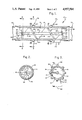
- FIG. 1 is a sectional view through the implantable blood pump of this invention.
- FIG. 2 is a sectional view taken generally along the line 2--2 in FIG. 1.
- FIG. 3 is a sectional view taken generally along the line 3--3 in FIG. 1.
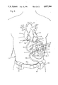
- FIG. 4 is a partial view of a human torso showing the manner in which two implantable blood pumps are connected to the apex of the left ventricle at one end and the descending aorta at the other end.
- FIGS. 1 through 3 A section of the implantable blood pump of this invention is illustrated in FIGS. 1 through 3, the pump being indicated generally at 10.
- the pump 10 is made of the fewest possible number of moving parts as practical.
- the pump is an integral part of an electric motor, the rotor of the motor serving as the device which, when rotated, causes the flow of blood through the pump casing, the casing in turn being the motor stator.
- the pump consists of only one moving part, this being a rotor indicated generally at 12, the rotor being mounted for rotation within the cylindrical opening 14 of a stator 16.
- the rotor consists essentially of an Archimedes screw or helix 18 which is supported by a shaft 20 having reduced end portions 22.
- the outer peripheral surface 24 of the helix 18 lies in a cylinder generated about the axis of the shaft 20, the axis being indicated by the dot-dash line 26. While only a single flighted rotor is shown, if desirable a rotor employing more than one flight may be employed. Similarly, while only a fixed-pitch flight is shown, if desirable a variable-pitched flight or flights may be employed.
- the rotor is mounted in such a manner that its axis is concentric with the axis of the cylindrical opening 14, and it should be noted that the periphery 24 of the rotor is disposed close to the surface of the cylindrical opening 14.
- each bearing 28 consists essentially of two or more radially extending arms 30, three being shown, the outer ends of which are joined with the stator, and the inner ends of the arms terminating in an annular bearing portion 32 which receives the reduced end portion 22 of the rotor 12.
- a reduced portion 22 at the end of the shaft 20 a step surface being formed between the reduced end portion and the shaft, which step surface may act as a thrust bearing.
- a bearing sleeve 34 within the annular portion 32 of the bearing, the bearing sleeve being formed of a suitable non-thrombogenic material.
- the rotor and stator may be formed of graphite covered by a very thin layer of pyrolitic carbon.
- the rotor and stator could be formed of silicone modified polyurethane.
- Other suitable materials may be pyrolitic carbon over metal, or polished and waxed Vitallium, an alloy of chromium, by molybdenum and cobalt. The above materials are given merely as examples and applicant does not intend to be limited to such examples as other suitable non-thrombogenic materials may be used.
- each array consists of a plurality of electromagnets which may be of any suitable design well known to those having ordinary skill in the art.
- each electromagnet may be a coil 40 wrapped about a soft iron slug 42, however other forms of electromagnets may be used.
- Each array 36, 38, of electromagnets lies in a plane which is transverse to the axis 26 of the rotor 12.
- a controller 44 in the form of a suitable electronic circuit or integrated circuit is provided, the controller being mounted upon the stator 16.
- the controller is suitably interconnected with the arrays of electromagnets so that each array may be sequentially operated, for example in the manner indicated by the arrow 46 in FIG. 3.
- the top electromagnet 40, 42 may be first energized, then the next electromagnet in the direction of the arrow 46, then each succeeding electromagnet.
- Each array of electromagnets cooperates with a permanent magnet 48 carried by the periphery of the rotor helix, there being a magnet disposed in the plane of each of the arrays 36, 38. Therefore, as the electromagnets of the arrays 36, 38 are sequentially energized in the direction of the arrow 46, the permanent magnets 48 will be caused to be rotated in the same direction thus driving the rotor 12.
- the external surface of the permanent magnets 48 are not exposed, but are in fact covered by a suitable non-thrombogenic material which is transparent to magnetic forces.
- electromagnets 40, 42 and control means 44 are shown exposed to the exterior side of the stator 16, they are preferably covered.
- the electromagnets and controller 44 may be embedded in a suitable potting compound which is either compatible with its surroundings, or which may be covered by a material having a suitable biocompatability, such as for example a dacron mesh which would promote tissue ingrowth.
- an external cylindrical structure may be disposed about the electromagnets, as for example a sleeve having two reduced end portions.
- a sleeve could be formed of a polyurethane or silicone rubber or other materials known to be suitable for implantation in human tissue.
- any suitable connections may be utilized.
- the closed helix 18 be made of a light weight material.
- a light weight material such as graphite covered with pyrolitic carbon
- the pump When used as a pulsatile pump the pump may be accelerated from a low speed or free wheeling condition to a speed as high as approximately 1200 rpms in a very brief time interval and then be permitted to coast down to a speed of approximately 50 rpm or whatever minimum speed is necessary to prevent the blood from stagnating within the pump, thus further minimizing the possibility of clots forming within the blood.
- the heart beat sensing means may be an EKG pick-up device 50 (Fig. 4) mounted upon any suitable location of the heart H. Alternatively, pressure or motion sensing devices may also be used to sense contractions of the heart. In any event, the heart beat sensing means will be suitably interconnected with the controller 44 by lead wires, such as that shown at 52.
- rotor sensing devices may also be used, and one such rotor sensing device may be a Hall-effect sensor 54 (FIG. 3) mounted between two adjacent electromagnets 40, 42, the Hall-effect sensor in turn being interconnected with the controller 44 by suitable lead wires 56. While a Hall-effect sensor is shown, it should be appreciated that other forms of devices may be used to sense either rotational speed of the rotor or even alternatively the pump output.
- the small diameter of the pump permits such variations as may be desired, and additionally, by ensuring that the pump never comes to rest by always maintaining a suitable munimum speed, it is possible to prevent blood stagnation and, with the use of suitable non-thrombogenic materials, minimize clot formation.
- the pump of this invention may be powered by external rechargeable battery packs carried in pockets 58 on the belt 60. Also mounted on the belt 60 is an external controller 62 which may be utilized to adjust the operation of the internal controller 44.
- the controller and battery packs are interconnected with the controllers 44 by a transcutaneous port (not shown) and wiring harness 64.
- the pump Because of the relatively small size of the pump, which may be 3/4-inch in diameter by 21/2 inches in length, because of its ability to produce either continuous or pulsatile blood flow, and also because of its capacity which may range from 1 to 4 liters per minute per pump, the pump may be used in a number of differing applications. In addition, by merely varying the diameter of the pump or by changing the flighting of the rotor it is possible also to vary the flow range of the pump in a manner well known in the art. Therefore, while the output of the preferred pump size may range from 1 to 4 liters per minute, it is possible to substantially increase the output of a single pump up to approximately 8 liters per minute or more. In any event because of its wide flexibility the pump may be used as either a heart assist device, or for substituting for total heart action depending on the connections made to the cardiovascular system.
- FIG. 4 one application of the implantable heart pump of this invention is illustrated wherein two parallel pumps are used as a left ventricular assist device.
- the patient's thorax is indicated by the letter T
- the diaphragm by the letter D
- the heart by the letter H
- the aorta by the letter A.
- the aortic arch is represented at AA
- the left ventricle at LV
- the apex of the left ventricle at LVA two pumps 10.1 and 10.2 are mounted in parallel and are used as a left ventricular assist.
- each of the two pumps is connected to the outer end of one of two branches 66 of a first bifurcated synthetic arterial prosthesis, frequently called a graft, indicated generally at 68, the outer end of the main trunk 70 of the arterial prosthesis 68 being sutured or otherwise suitably secured to the apex LVA of the left ventricle LV.
- the outlet ends of the two parallel pumps are in turn connected to the outer end of the branches 72 of a second bifurcated graft 74, the outer end of the trunk portion 76 being interconnected with the descending aorta A by suturing or the like below the renal artery (not indicated).
- the manner in which each of the pumps is connected to the branches will be apparent to those of ordinary skill in the art.
- the controller 44 of each of the pumps 10.1 and 10.2 will be interconnected with each other by means of a harness 78.
- the lead wires 52 and 56 from the heart beat sensing device 50 and the rotor speed sensing means 54 will in turn be interconnected with one of the controllers 44, but by interconnecting the controllers to each other through the harness 78, it will be possible to control each of the pumps in response to the sensed signal.
- one of the two pumps can be run continuously while the other of the two pumps can be operated as a pulsatile pump in response to heart beats.
- both pumps could be run as pulsatile pumps, continuous pumps, or the pumps could alternate between pulsatile peak output and continuous flow.
- pump 10.1 can be run up to a pulsatile pump peak output of say approximately 1200 rpms during a first heart beat, be permitted to coast down to a continuous flow operating range of approximately 400 rpms during a second heart beat, and then be run up to a pulsatile peak output of approximately 1200 rpm during a third heart beat, and so on.
- the other pump 10.2 can start out initially at a continuous flow speed of approximately 400 rpm during the first heart beat, then be run up to pulsatile peak speed of approximately 1200 rpm during the second heart beat, and then be permitted to coast down to continuous flow speed of approximately 400 rpm during a third heart beat, and so on.
- Bifurcated arterial prosthesis are well known in the art and one such arterial prosthesis is the aorta-femoral arterial prosthesis. Other suitable arterial prosthesis may be employed or developed.
- the pumps 10 may be desirable to use the pumps 10 in other arrangements.
- total heart function may be achieved where the left ventricle is interconnected with the aorta arch by one or more pumps and the right ventricle is interconnected with another pump for discharge to the pulmonary artery.
- an auricle may be tapped.
- a single pump may be utilized to connect the apex of the left ventricle to the aorta.
- Other applications of the implantable blood pump of this design will be apparent to those of ordinary skill in the art. While the pumps are shown below the diaphragm D in FIG. 4, one or more pumps may be disposed above the diaphragm, with all connections being above the diaphragm.
- the above pump design which is very simple in construction, avoids the pitfalls of bladder type devices which have been associated with clotting and emboli.
- the present device does not require any valves and is of a very simple design.
- the pump 10 depending upon the manner in which it is energized, can provide either continuous flow or a pulsatile flow. In addition it is possible to achieve both pulsatile or continuous flow. As the capacity of the pump can be increased by simply increasing its diameter, say for example from three quarters of an inch to one inch, the flow can be varied from a partial assist to a total assist.
- the power supply is connected to the pump by a cable fed through a transcutaneous port it is also possible to transmit electrical power from an externally located coil to a subcutaneously implanted coil, thus avoiding all transcutaneous pathways.
- the internal controller(s) 44 may be reprogrammed by radio frequency signals through intact skin rather than by harness 64.
Abstract
An implantable blood pump (10) for providing either continuous or pulsatile blood flow to the heart. The pump includes a stator (16) having a cylindrical opening (14), an annular array (36 or 38) of electromagnets (40, 42) carried by the stator concentric with the cylindrical opening and lying in a plane transverse to the axis (26) of the opening, a bearing (28) carried by the stator and extending across the cylindrical opening, and a rotor (12) supported by the bearing for rotation about the axis of the cylindrical opening, the rotor being in the form of an Archimedes screw and having a permanent magnet (48) in its periphery which lies in the same plane as the array of electromagnets. A controller (44) is provided which is capable of causing the array of electromagnets to be sequentially energized to cause the rotor to rotate. A heart beat sensing device (50) and a rotor speed sensing device (54) may be associated with the controller so the controller may vary the rotational speed of the rotor so that the output of the pump is varied between a high ouptut synchronized with a heart beat and a low output.
Description
This invention relates generally to implantable blood pumps, and more particularly to a rotary blood pump capable of providing continuous or pulsatile blood flow to the body, the pump being of a reliable design and having power requirements that can be satisfied by presently available rechargeable batteries small enough to allow the patient to lead a normal life.
In advanced cardiac or heart failure the output of the heart may drop from its normal resting output of about 5 liters a minute to an output approaching 2 liters of blood per minute. As output reaches this low level, the kidneys, liver, and brain become irreversibly damaged. In recent years different approaches have been used to treat irreversible cardiac failure. One approach is the removal of the heart and transplantation of a donar organ. While recipients now have a good chance of leading a normal life, obviously the supply of donor organs is limited. Artificial hearts have not been successful as permanent replacements, but have been used on a temporary basis as a "bridge" until a donor heart becomes available. Temporary partial assist devices have been used for acutely failing hearts expected to recover within a matter of days. One such partial assist design is shown in U.S. Pat. No. 4,704,121 which discloses a transarterial insertable blood pump. This device requires a drive cable which extends to the outside of the body of the patient. The pump of this design rotates at an extremely high speed. While this patent does address the problem of blood clotting, the complexities of its design detract from its reliability and additionally the high speed operation has created problems of drive cable reliability. This device also requires an external or internal purge supply, so constant replenishment of the fluid is necessary. In addition to the assist device of the above patent, a mechanical device which entirely replaces heart function has also been proposed, and one such example is shown in the Jarvik patent No. 4,173,796. This type of pump relies upon bladders shifting the blood between two chambers and also requires valves. Typically there is blood stagnation within this form of pump causing the formation of blood clots. This design is also unduly complicated because of its requirement for valves.
All prior art mechanical devices known to date have produced thrombosis and embolization in excess of that normaly produced by the body. In addition, the designs have been complicated and required bulky power supples thereby preventing a normal life.
It is an object of the present invention to provide an implantable blood pump which overcomes the disadvantages of prior art mechanical implantable blood pumps.
More specifically, it is an object of the present invention to provide an implantable blood pump which is simple, has no valves, is capable of producing from 2 to 8 liters per minute against a mean pressure head of 100 to 120 ml, minimizes clotting, does not require removal of the heart, and yet will permit the patient to lead a normal life.
It is another object of the present invention to provide an implantable blood pump which, as understood in physiology, is capable of pulsatile or continuous flow.
It is another object of the present invention to provide an implantable blood pump wherein the blood pump has only a single moving part, this being the rotor of an electromagnetic motor, the rotor being disposed within a stator which forms the pump casing, and the rotor being in the form of a helix of Archimedes screw.
In accordance with the present invention there is provided an implantable blood pump capable of providing either continuous or pulsatile blood flow to the body. The pump includes a stator having a cylindrical opening, an array of electromagnets carried by the stator, a bearing member carried by the stator and extending across the cylindrical opening, and a rotor supported by the bearing member for rotation about the axis of the cylindrical opening. The electromagnets are disposed adjacent the inner surface of the stator, concentric with and in a plane transverse to the axis of the cylindrical opening and are capable of being sequentially energized. The rotor is in the form of a helix and includes at least one permanent magnet embedded in the periphery thereof, the permanent magnet lying in the plane of the annular array of electromagnets so that when the electromagnets are sequentially energized the rotor will be caused to rotate. The surfaces of the stator and the rotor which are exposed to blood flow are constructed of biocompatible materials known to be thrombo-resistant.
The foregoing and other objects and advantages of this invention will become more apparent after a consideration of the following detailed description taken in conjunction with the accompanying drawings in which preferred form of this invention is illustrated.
FIG. 1 is a sectional view through the implantable blood pump of this invention.
FIG. 2 is a sectional view taken generally along the line 2--2 in FIG. 1.
FIG. 3 is a sectional view taken generally along the line 3--3 in FIG. 1.
FIG. 4 is a partial view of a human torso showing the manner in which two implantable blood pumps are connected to the apex of the left ventricle at one end and the descending aorta at the other end.
A section of the implantable blood pump of this invention is illustrated in FIGS. 1 through 3, the pump being indicated generally at 10. In order to increase reliability of design the pump 10 is made of the fewest possible number of moving parts as practical. As will become apparent the pump is an integral part of an electric motor, the rotor of the motor serving as the device which, when rotated, causes the flow of blood through the pump casing, the casing in turn being the motor stator. Thus, the pump consists of only one moving part, this being a rotor indicated generally at 12, the rotor being mounted for rotation within the cylindrical opening 14 of a stator 16. The rotor consists essentially of an Archimedes screw or helix 18 which is supported by a shaft 20 having reduced end portions 22. The outer peripheral surface 24 of the helix 18 lies in a cylinder generated about the axis of the shaft 20, the axis being indicated by the dot-dash line 26. While only a single flighted rotor is shown, if desirable a rotor employing more than one flight may be employed. Similarly, while only a fixed-pitch flight is shown, if desirable a variable-pitched flight or flights may be employed. The rotor is mounted in such a manner that its axis is concentric with the axis of the cylindrical opening 14, and it should be noted that the periphery 24 of the rotor is disposed close to the surface of the cylindrical opening 14. To this end, the rotor is supported by suitable bearings indicated generally at 28, which bearings are carried by the stator and extend across the cylindrical opening, there being a bearing 28 at either end of the stator 16. Each bearing 28 consists essentially of two or more radially extending arms 30, three being shown, the outer ends of which are joined with the stator, and the inner ends of the arms terminating in an annular bearing portion 32 which receives the reduced end portion 22 of the rotor 12. In the bearing shown, a reduced portion 22 at the end of the shaft 20, a step surface being formed between the reduced end portion and the shaft, which step surface may act as a thrust bearing. It may be desirable in certain situations to provide a bearing sleeve 34 within the annular portion 32 of the bearing, the bearing sleeve being formed of a suitable non-thrombogenic material. In this connection it should also be noted that all surfaces of the rotor, stator and bearings which are exposed to the blood being pumped by pump 10 are similarly formed of non-thrombogenic materials. For example, the rotor and stator may be formed of graphite covered by a very thin layer of pyrolitic carbon. Similarly, the rotor and stator could be formed of silicone modified polyurethane. Other suitable materials may be pyrolitic carbon over metal, or polished and waxed Vitallium, an alloy of chromium, by molybdenum and cobalt. The above materials are given merely as examples and applicant does not intend to be limited to such examples as other suitable non-thrombogenic materials may be used.
In a preferred design two annular arrays of electromagnets are carried by the stator, the first array being indicated generally at 36, and the second array being indicated generally at 38. Each array consists of a plurality of electromagnets which may be of any suitable design well known to those having ordinary skill in the art. Thus, as shown in the drawings, each electromagnet may be a coil 40 wrapped about a soft iron slug 42, however other forms of electromagnets may be used. Each array 36, 38, of electromagnets lies in a plane which is transverse to the axis 26 of the rotor 12. In order to properly operate the electromagnets a controller 44 in the form of a suitable electronic circuit or integrated circuit is provided, the controller being mounted upon the stator 16. The controller is suitably interconnected with the arrays of electromagnets so that each array may be sequentially operated, for example in the manner indicated by the arrow 46 in FIG. 3. Thus, with further reference to FIG. 3, the top electromagnet 40, 42 may be first energized, then the next electromagnet in the direction of the arrow 46, then each succeeding electromagnet. Each array of electromagnets cooperates with a permanent magnet 48 carried by the periphery of the rotor helix, there being a magnet disposed in the plane of each of the arrays 36, 38. Therefore, as the electromagnets of the arrays 36, 38 are sequentially energized in the direction of the arrow 46, the permanent magnets 48 will be caused to be rotated in the same direction thus driving the rotor 12. The external surface of the permanent magnets 48 are not exposed, but are in fact covered by a suitable non-thrombogenic material which is transparent to magnetic forces. When the helix 18 is rotated blood will be pumped through the pump casing or stator 16.
While the electromagnets 40, 42 and control means 44 are shown exposed to the exterior side of the stator 16, they are preferably covered. Thus, the electromagnets and controller 44 may be embedded in a suitable potting compound which is either compatible with its surroundings, or which may be covered by a material having a suitable biocompatability, such as for example a dacron mesh which would promote tissue ingrowth. Alternatively, an external cylindrical structure may be disposed about the electromagnets, as for example a sleeve having two reduced end portions. Such a sleeve could be formed of a polyurethane or silicone rubber or other materials known to be suitable for implantation in human tissue. Also, while the manner in which the coils 40 are connected to the controller 44 is not shown, it should be appreciated that any suitable connections may be utilized.
It is desirable that the closed helix 18 be made of a light weight material. By utilizing a light weight material, such as graphite covered with pyrolitic carbon, there are low inertial forces. This is particularly desirable when the rotor is to be selectively energized as when the pump is to be used to produce a pulsatile flow. When used as a pulsatile pump the pump may be accelerated from a low speed or free wheeling condition to a speed as high as approximately 1200 rpms in a very brief time interval and then be permitted to coast down to a speed of approximately 50 rpm or whatever minimum speed is necessary to prevent the blood from stagnating within the pump, thus further minimizing the possibility of clots forming within the blood. In order to properly time pulsatile blood flow it is necessary to provide heart beat sensing means and to have the maximum blood flow coincide with a heart beat. Similarly, in order to maintain a minimum blood flow to prevent the formation of blood clots. Which minimum flow blood flow may be between every other heart beat, it is necessary to provide rotor speed sensing means. The heart beat sensing means may be an EKG pick-up device 50 (Fig. 4) mounted upon any suitable location of the heart H. Alternatively, pressure or motion sensing devices may also be used to sense contractions of the heart. In any event, the heart beat sensing means will be suitably interconnected with the controller 44 by lead wires, such as that shown at 52. Various forms of rotor sensing devices may also be used, and one such rotor sensing device may be a Hall-effect sensor 54 (FIG. 3) mounted between two adjacent electromagnets 40, 42, the Hall-effect sensor in turn being interconnected with the controller 44 by suitable lead wires 56. While a Hall-effect sensor is shown, it should be appreciated that other forms of devices may be used to sense either rotational speed of the rotor or even alternatively the pump output.
By using the particular pump described above it is possible to either provide continuous blood flow where the electromagnets are sequentially operated at a constant speed or a pulsatile blood flow where the speed of the electromagnets varies to impart varying rotational speeds to the rotor. In any event, the small diameter of the pump permits such variations as may be desired, and additionally, by ensuring that the pump never comes to rest by always maintaining a suitable munimum speed, it is possible to prevent blood stagnation and, with the use of suitable non-thrombogenic materials, minimize clot formation.
As shown in FIG. 4 the pump of this invention may be powered by external rechargeable battery packs carried in pockets 58 on the belt 60. Also mounted on the belt 60 is an external controller 62 which may be utilized to adjust the operation of the internal controller 44. The controller and battery packs are interconnected with the controllers 44 by a transcutaneous port (not shown) and wiring harness 64.
Because of the relatively small size of the pump, which may be 3/4-inch in diameter by 21/2 inches in length, because of its ability to produce either continuous or pulsatile blood flow, and also because of its capacity which may range from 1 to 4 liters per minute per pump, the pump may be used in a number of differing applications. In addition, by merely varying the diameter of the pump or by changing the flighting of the rotor it is possible also to vary the flow range of the pump in a manner well known in the art. Therefore, while the output of the preferred pump size may range from 1 to 4 liters per minute, it is possible to substantially increase the output of a single pump up to approximately 8 liters per minute or more. In any event because of its wide flexibility the pump may be used as either a heart assist device, or for substituting for total heart action depending on the connections made to the cardiovascular system.
Referring now to FIG. 4, one application of the implantable heart pump of this invention is illustrated wherein two parallel pumps are used as a left ventricular assist device. In this view the patient's thorax is indicated by the letter T, the diaphragm by the letter D, the heart by the letter H, and the aorta by the letter A. In addition, the aortic arch is represented at AA, the left ventricle at LV, and the apex of the left ventricle at LVA. In the application shown in this figure, two pumps 10.1 and 10.2 are mounted in parallel and are used as a left ventricular assist. To this end, the inlet end of each of the two pumps is connected to the outer end of one of two branches 66 of a first bifurcated synthetic arterial prosthesis, frequently called a graft, indicated generally at 68, the outer end of the main trunk 70 of the arterial prosthesis 68 being sutured or otherwise suitably secured to the apex LVA of the left ventricle LV. The outlet ends of the two parallel pumps are in turn connected to the outer end of the branches 72 of a second bifurcated graft 74, the outer end of the trunk portion 76 being interconnected with the descending aorta A by suturing or the like below the renal artery (not indicated). The manner in which each of the pumps is connected to the branches will be apparent to those of ordinary skill in the art. The controller 44 of each of the pumps 10.1 and 10.2 will be interconnected with each other by means of a harness 78. The lead wires 52 and 56 from the heart beat sensing device 50 and the rotor speed sensing means 54 will in turn be interconnected with one of the controllers 44, but by interconnecting the controllers to each other through the harness 78, it will be possible to control each of the pumps in response to the sensed signal. In this embodiment one of the two pumps can be run continuously while the other of the two pumps can be operated as a pulsatile pump in response to heart beats. Alternatively, both pumps could be run as pulsatile pumps, continuous pumps, or the pumps could alternate between pulsatile peak output and continuous flow. For example, pump 10.1 can be run up to a pulsatile pump peak output of say approximately 1200 rpms during a first heart beat, be permitted to coast down to a continuous flow operating range of approximately 400 rpms during a second heart beat, and then be run up to a pulsatile peak output of approximately 1200 rpm during a third heart beat, and so on. Meanwhile, the other pump 10.2 can start out initially at a continuous flow speed of approximately 400 rpm during the first heart beat, then be run up to pulsatile peak speed of approximately 1200 rpm during the second heart beat, and then be permitted to coast down to continuous flow speed of approximately 400 rpm during a third heart beat, and so on. In this way the load is constantly switched between the two pumps, and pulsatile flow is achieved. By discharging into the descending aorta below the renal arteries there is less potential chance of injury to the patient due to the formation of very small blood clots as the circulatory system below the renal artery is capable of dissolving small clots which are formed during normal circulation. Bifurcated arterial prosthesis are well known in the art and one such arterial prosthesis is the aorta-femoral arterial prosthesis. Other suitable arterial prosthesis may be employed or developed.
While a novel parallel pump application is shown, it may be desirable to use the pumps 10 in other arrangements. For example, total heart function may be achieved where the left ventricle is interconnected with the aorta arch by one or more pumps and the right ventricle is interconnected with another pump for discharge to the pulmonary artery. Instead of connecting to a ventricle an auricle may be tapped. Alternatively, as an assist device only a single pump may be utilized to connect the apex of the left ventricle to the aorta. Other applications of the implantable blood pump of this design will be apparent to those of ordinary skill in the art. While the pumps are shown below the diaphragm D in FIG. 4, one or more pumps may be disposed above the diaphragm, with all connections being above the diaphragm.
The above pump design, which is very simple in construction, avoids the pitfalls of bladder type devices which have been associated with clotting and emboli. In addition, the present device does not require any valves and is of a very simple design. The pump 10, depending upon the manner in which it is energized, can provide either continuous flow or a pulsatile flow. In addition it is possible to achieve both pulsatile or continuous flow. As the capacity of the pump can be increased by simply increasing its diameter, say for example from three quarters of an inch to one inch, the flow can be varied from a partial assist to a total assist.
It should be noted that while in this description the power supply is connected to the pump by a cable fed through a transcutaneous port it is also possible to transmit electrical power from an externally located coil to a subcutaneously implanted coil, thus avoiding all transcutaneous pathways. Also, the internal controller(s) 44 may be reprogrammed by radio frequency signals through intact skin rather than by harness 64.
While a preferred structure in which the principles of the present invention have been incorporated is shown and described above, it is to be understood that this invention is not to be limited to the particular details shown and described above, but that, in fact, widely differing means may be employed in the broader aspects of this invention.
Claims (9)
1. An implantable and biocompatible blood pump capable of providing either continuous or pulsatile blood flow, the pump comprising:
a stator having a cylindrical opening;
bearing means carried by the stator and extending across the cylindrical opening;
a rotor supported by the bearing means for rotation about the axis of the cylindrical opening, the rotor being in the form of a helix; and
electromagnetic means carried by the stator for driving the rotor.
2. The pump as set forth in claim 1, wherein a permanent magnet is embedded in the periphery of the rotor and the electromagnetic means is an annular array of electromagnets carried by the stator and concentric with the axis of the cylindrical opening, the array lying in a plane transverse to the axis of the cylindrical opening, which plane passes through the permanent magnet carried by the rotor, and wherein the electromagnets are capable of being sequentially energized.
3. The pump as set forth in claim 2 wherein a second annular array of electromagnets is carried by the stator in a second plane parallel to the first plane, there being a second permanent magnet carried by the rotor and lying in the plane of the second array of electromagnets.
4. The pump set forth in claim 1 wherein the helix is closed.
5. The pump as set forth in claim 1 wherein the bearing means are disposed at both ends of the cylindrical opening, opposite ends of the helix being supported by the bearing means.
6. The pump as set forth in claim 1 wherein all surfaces of the stator, rotor, and bearing which are exposed to the blood being pumped are made of non-thrombogenic materials.
7. The pump as set forth in claim 1 further comprising control means interconnected with the electromagnetic means and capable of operating the electromagnetic means in such a manner that the rotor is driven at varying speeds.
8. The pump as set forth in claim 7 further comprising heart beat sensing means capable of sensing a heart beat, the heart beat sensing means being interconnected with the control means, the control means being capable of increasing the output of the pump in sychronism with the heart beat.
9. The pump as set forth in claim 8 further comprising rotor sensing means capable of sensing the rotational speed of the rotor, said control means additionally being interconnected with the rotor sensing means and said control means being capable of ensuring that the rotor will be rotated at all times to ensure that blood within the pump is always in motion and does not stagnate.
Priority Applications (1)
| Application Number | Priority Date | Filing Date | Title |
|---|---|---|---|
| US07/278,788 US4957504A (en) | 1988-12-02 | 1988-12-02 | Implantable blood pump |
Applications Claiming Priority (1)
| Application Number | Priority Date | Filing Date | Title |
|---|---|---|---|
| US07/278,788 US4957504A (en) | 1988-12-02 | 1988-12-02 | Implantable blood pump |
Publications (1)
| Publication Number | Publication Date |
|---|---|
| US4957504A true US4957504A (en) | 1990-09-18 |
Family
ID=23066366
Family Applications (1)
| Application Number | Title | Priority Date | Filing Date |
|---|---|---|---|
| US07/278,788 Expired - Fee Related US4957504A (en) | 1988-12-02 | 1988-12-02 | Implantable blood pump |
Country Status (1)
| Country | Link |
|---|---|
| US (1) | US4957504A (en) |
Cited By (226)
| Publication number | Priority date | Publication date | Assignee | Title |
|---|---|---|---|---|
| US4994078A (en) * | 1988-02-17 | 1991-02-19 | Jarvik Robert K | Intraventricular artificial hearts and methods of their surgical implantation and use |
| US5092844A (en) * | 1990-04-10 | 1992-03-03 | Mayo Foundation For Medical Education And Research | Intracatheter perfusion pump apparatus and method |
| US5112200A (en) * | 1990-05-29 | 1992-05-12 | Nu-Tech Industries, Inc. | Hydrodynamically suspended rotor axial flow blood pump |
| US5112349A (en) * | 1988-09-27 | 1992-05-12 | American Biomed, Inc. | Heart assist pump |
| US5163910A (en) * | 1990-04-10 | 1992-11-17 | Mayo Foundation For Medical Education And Research | Intracatheter perfusion pump apparatus and method |
| US5205721A (en) * | 1991-02-13 | 1993-04-27 | Nu-Tech Industries, Inc. | Split stator for motor/blood pump |
| US5211546A (en) * | 1990-05-29 | 1993-05-18 | Nu-Tech Industries, Inc. | Axial flow blood pump with hydrodynamically suspended rotor |
| US5219276A (en) * | 1991-02-27 | 1993-06-15 | Fresenius Ag | Pump, in particular an enclosed medical pump |
| EP0560000A2 (en) * | 1991-11-05 | 1993-09-15 | Roberto Parravicini | Ventricular pumping device |
| US5290227A (en) * | 1992-08-06 | 1994-03-01 | Pasque Michael K | Method of implanting blood pump in ascending aorta or main pulmonary artery |
| US5300112A (en) * | 1992-07-14 | 1994-04-05 | Aai Corporation | Articulated heart pump |
| US5344385A (en) * | 1991-09-30 | 1994-09-06 | Thoratec Laboratories Corporation | Step-down skeletal muscle energy conversion system |
| US5376114A (en) * | 1992-10-30 | 1994-12-27 | Jarvik; Robert | Cannula pumps for temporary cardiac support and methods of their application and use |
| WO1995023000A2 (en) * | 1994-02-25 | 1995-08-31 | General Dynamics Corporation | Reciprocating pump arrangement |
| US5527159A (en) * | 1993-11-10 | 1996-06-18 | The United States Of America As Represented By The Administrator Of The National Aeronautics And Space Administration | Rotary blood pump |
| US5613935A (en) * | 1994-12-16 | 1997-03-25 | Jarvik; Robert | High reliability cardiac assist system |
| US5643215A (en) * | 1995-02-24 | 1997-07-01 | The Research Foundation Of State University Of New York | Gas exchange apparatus and method |
| WO1998028543A2 (en) | 1996-12-23 | 1998-07-02 | Nuesser Peter | Device for feeding single-phase and polyphase fluids |
| US5828149A (en) * | 1996-07-18 | 1998-10-27 | Baker Hughes Incorported | Lubricant inducer pump for electrical motor |
| US5840070A (en) * | 1996-02-20 | 1998-11-24 | Kriton Medical, Inc. | Sealless rotary blood pump |
| US5851174A (en) * | 1996-09-17 | 1998-12-22 | Robert Jarvik | Cardiac support device |
| WO1999017819A1 (en) * | 1997-10-02 | 1999-04-15 | Micromed Technology, Inc. | Implantable pump system |
| WO1999019010A1 (en) * | 1997-10-09 | 1999-04-22 | Fore Flow Corporation | Implantable heart assist system |
| EP0884064A3 (en) * | 1997-06-12 | 1999-06-09 | Schneider (Usa) Inc. | Balloon Catheter with impeller for perusing blood |
| US5941813A (en) * | 1996-07-23 | 1999-08-24 | Cardiotools Herzchirurgietechnik Gmbh | Cardiac assist device |
| US5947892A (en) * | 1993-11-10 | 1999-09-07 | Micromed Technology, Inc. | Rotary blood pump |
| US5951262A (en) * | 1997-04-18 | 1999-09-14 | Centriflow Llc | Mechanism for providing motive force and for pumping applications |
| GB2335146A (en) * | 1997-11-26 | 1999-09-15 | Vascor Inc | Magnetically suspended fluid pump and control system |
| US5957672A (en) * | 1993-11-10 | 1999-09-28 | The United States Of America As Represented By The Administrator Of The National Aeronautics And Space Administration | Blood pump bearing system |
| US5965089A (en) * | 1996-10-04 | 1999-10-12 | United States Surgical Corporation | Circulatory support system |
| US6015272A (en) * | 1996-06-26 | 2000-01-18 | University Of Pittsburgh | Magnetically suspended miniature fluid pump and method of designing the same |
| GB2340404A (en) * | 1997-11-26 | 2000-02-23 | Vascor Inc | Apparatus for operating a blood pump |
| US6042347A (en) * | 1998-07-27 | 2000-03-28 | Scholl; Frank G. | Pedia-cadio pump |
| US6048363A (en) * | 1997-05-13 | 2000-04-11 | Nagyszalanczy; Lorant | Centrifugal blood pump apparatus |
| JP2000102605A (en) * | 1998-09-29 | 2000-04-11 | Kyocera Corp | Centrifugal blood pump |
| US6120537A (en) * | 1997-12-23 | 2000-09-19 | Kriton Medical, Inc. | Sealless blood pump with means for avoiding thrombus formation |
| US6123725A (en) * | 1997-07-11 | 2000-09-26 | A-Med Systems, Inc. | Single port cardiac support apparatus |
| WO2000061207A1 (en) * | 1999-04-09 | 2000-10-19 | Orqis Medical Corporation | Heart assist system |
| WO2000062842A1 (en) | 1999-04-20 | 2000-10-26 | Berlin Heart Ag | Device for the axial transport of fluid media |
| US6149683A (en) * | 1998-10-05 | 2000-11-21 | Kriton Medical, Inc. | Power system for an implantable heart pump |
| WO2001026202A1 (en) * | 1999-10-07 | 2001-04-12 | Advanced Rotary Systems, Llc | Axial fluid flow inducing device with multiple magnetically driven impellers |
| US6234772B1 (en) | 1999-04-28 | 2001-05-22 | Kriton Medical, Inc. | Rotary blood pump |
| US6245007B1 (en) | 1999-01-28 | 2001-06-12 | Terumo Cardiovascular Systems Corporation | Blood pump |
| US6244835B1 (en) * | 1996-06-26 | 2001-06-12 | James F. Antaki | Blood pump having a magnetically suspended rotor |
| US6254359B1 (en) * | 1996-05-10 | 2001-07-03 | The United States Of America As Represented By The Administrator Of The National Aeronautics And Space Administration | Method for providing a jewel bearing for supporting a pump rotor shaft |
| US6293901B1 (en) | 1997-11-26 | 2001-09-25 | Vascor, Inc. | Magnetically suspended fluid pump and control system |
| US6331188B1 (en) | 1994-08-31 | 2001-12-18 | Gore Enterprise Holdings, Inc. | Exterior supported self-expanding stent-graft |
| GB2365348A (en) * | 1999-02-09 | 2002-02-20 | Vascor Inc | Blood pump and control system |
| US6352561B1 (en) | 1996-12-23 | 2002-03-05 | W. L. Gore & Associates | Implant deployment apparatus |
| US6352553B1 (en) | 1995-12-14 | 2002-03-05 | Gore Enterprise Holdings, Inc. | Stent-graft deployment apparatus and method |
| US6361637B2 (en) | 1995-12-14 | 2002-03-26 | Gore Enterprise Holdings, Inc. | Method of making a kink resistant stent-graft |
| US6390969B1 (en) | 1997-10-09 | 2002-05-21 | Orqis Medical Corporation | Implantable heart assist system and method of applying same |
| US6422990B1 (en) | 1997-11-26 | 2002-07-23 | Vascor, Inc. | Blood pump flow rate control method and apparatus utilizing multiple sensors |
| GB2371230A (en) * | 2001-02-08 | 2002-07-24 | Tayside Flow Technologies Ltd | Pumps |
| US20020188167A1 (en) * | 2001-06-06 | 2002-12-12 | Anthony Viole | Multilumen catheter for minimizing limb ischemia |
| US20030069468A1 (en) * | 1997-10-09 | 2003-04-10 | Bolling Steven F. | Implantable heart assist system and method of applying same |
| US6551350B1 (en) | 1996-12-23 | 2003-04-22 | Gore Enterprise Holdings, Inc. | Kink resistant bifurcated prosthesis |
| US6610004B2 (en) | 1997-10-09 | 2003-08-26 | Orqis Medical Corporation | Implantable heart assist system and method of applying same |
| US6613072B2 (en) | 1994-09-08 | 2003-09-02 | Gore Enterprise Holdings, Inc. | Procedures for introducing stents and stent-grafts |
| NL1023970C2 (en) * | 1999-02-09 | 2003-11-28 | Vascor Inc | Blood pump with magnetically suspended stator and rotor element with a flow rate controller. |
| US20040000554A1 (en) * | 2002-05-01 | 2004-01-01 | Jeffery Griffin | Static charge dissipater for filler neck closure |
| US20040024285A1 (en) * | 2002-06-21 | 2004-02-05 | Helmut Muckter | Blood pump with impeller |
| US20040028525A1 (en) * | 1997-09-05 | 2004-02-12 | Woodard John C. | Rotary pump with exclusively hydrodynamically suspended impeller |
| US20040030216A1 (en) * | 1997-09-05 | 2004-02-12 | Woodard John Campbell | Rotary pump with hydrodynamically suspended impeller |
| US20040080224A1 (en) * | 2001-04-19 | 2004-04-29 | Knox Dick L. | Pressurized bearing system for submersible motor |
| US20040097782A1 (en) * | 2001-03-13 | 2004-05-20 | Theodosios Korakianitis | Optimized pulsatile-flow ventricular-assist device and total artificial heart |
| US6742999B1 (en) | 1999-04-20 | 2004-06-01 | Berlin Heart Ag | Device for delivering single-phase or multiphase fluids without altering the properties thereof |
| US20040115038A1 (en) * | 2001-02-16 | 2004-06-17 | Peter Nuesser | Device for axially conveying fluids |
| US20040138519A1 (en) * | 2001-06-06 | 2004-07-15 | Anthony Viole | Multilumen catheter for minimizing limb ischemia |
| US20040215050A1 (en) * | 2002-01-07 | 2004-10-28 | Micromed Technology, Inc. | Blood pump system and method of operation |
| US20050071001A1 (en) * | 2003-09-30 | 2005-03-31 | Robert Jarvik | Artificial heart power and control system |
| US20050131271A1 (en) * | 2002-01-07 | 2005-06-16 | Micromed Technology Inc. | Method and system for physiologic control of an implantable blood pump |
| US20050228211A1 (en) * | 2004-04-12 | 2005-10-13 | Bryan Leasure | Cyclical pressure coronary assist pump |
| US20050261543A1 (en) * | 2004-05-18 | 2005-11-24 | Yusuke Abe | Implantable artificial ventricular assist device |
| US20050269885A1 (en) * | 2001-04-19 | 2005-12-08 | Baker Hughes Incorporated | Pressurized bearing system for submersible motor |
| US20060241544A1 (en) * | 2003-02-19 | 2006-10-26 | Axel Haverich | Methods and devices for improving cardiac output |
| US20060241335A1 (en) * | 2002-06-26 | 2006-10-26 | Benkowski Robert J | Method and system for physiologic control of a blood pump |
| US20060245959A1 (en) * | 2005-04-29 | 2006-11-02 | Larose Jeffrey A | Multiple rotor, wide blade, axial flow pump |
| US7182727B2 (en) | 1997-07-11 | 2007-02-27 | A—Med Systems Inc. | Single port cardiac support apparatus |
| US20070092382A1 (en) * | 2004-12-22 | 2007-04-26 | Pratt & Whitney Canada Corp. | Pump and method |
| US20070156006A1 (en) * | 2005-06-06 | 2007-07-05 | The Cleveland Clinic Foundation And Foster-Miller, Inc. | Blood pump |
| US20070265703A1 (en) * | 2006-05-09 | 2007-11-15 | Ventrassist Pty Ltd. | Pulsatile control system for a rotary blood pump |
| EP1893075A2 (en) * | 2005-06-08 | 2008-03-05 | Micromed Technology, Inc. | Artificial heart system |
| US20080056883A1 (en) * | 2006-09-01 | 2008-03-06 | Richard Lee | Axial-Flow Fluid Pressurizer |
| WO2008116765A2 (en) * | 2007-03-24 | 2008-10-02 | Abiomed Europe Gmbh | Blood pump comprising a micromotor |
| US7445592B2 (en) | 2004-06-10 | 2008-11-04 | Orqis Medical Corporation | Cannulae having reduced flow resistance |
| US20090138080A1 (en) * | 2005-04-16 | 2009-05-28 | Thorsten Siess | Method for Controlling a Blood Pump |
| US20090226328A1 (en) * | 2004-11-16 | 2009-09-10 | Micromed Technology, Inc. | Remote Data Monitor For Heart Pump System |
| US20100185280A1 (en) * | 1999-04-23 | 2010-07-22 | Ventrassist Pty. Ltd | Rotary blood pump and control system therefor |
| US20100197994A1 (en) * | 2007-07-18 | 2010-08-05 | Hormoz Mehmanesh | Cardiac Assist Device |
| US20100222633A1 (en) * | 2009-02-27 | 2010-09-02 | Victor Poirier | Blood pump system with controlled weaning |
| US20100222632A1 (en) * | 2009-02-27 | 2010-09-02 | Victor Poirier | Prevention of aortic valve fusion |
| US20100222634A1 (en) * | 2009-02-27 | 2010-09-02 | Thoratec Corporation | Blood flow meter |
| US7841976B2 (en) | 2006-03-23 | 2010-11-30 | Thoratec Corporation | Heart assist device with expandable impeller pump |
| US20110015465A1 (en) * | 2005-11-04 | 2011-01-20 | Peter Joseph Ayre | Control systems for rotary blood pumps |
| EP2292117A1 (en) * | 2009-08-28 | 2011-03-09 | Antje Schmidt | Belt holder device for an artificial heart system |
| EP2298375A1 (en) * | 2008-06-11 | 2011-03-23 | Sun Medical Technology Research Corporation | Artificial heart control device, artificial heart system, and artificial heart control method |
| US7927068B2 (en) | 2004-09-17 | 2011-04-19 | Thoratec Corporation | Expandable impeller pump |
| US7976271B2 (en) | 2006-01-13 | 2011-07-12 | Heartware, Inc. | Stabilizing drive for contactless rotary blood pump impeller |
| US20110178361A1 (en) * | 2010-01-19 | 2011-07-21 | Barry Yomtov | Physiologically responsive vad |
| US20110218384A1 (en) * | 2010-03-05 | 2011-09-08 | Minnetronix Inc. | Portable controller with integral power source for mechanical circulation support systems |
| US8118724B2 (en) | 2003-09-18 | 2012-02-21 | Thoratec Corporation | Rotary blood pump |
| WO2012040551A1 (en) * | 2010-09-24 | 2012-03-29 | Thoratec Corporation | Generating artificial pulse |
| US8449443B2 (en) | 2008-10-06 | 2013-05-28 | Indiana University Research And Technology Corporation | Active or passive assistance in the circulatory system |
| WO2013082621A1 (en) * | 2011-12-03 | 2013-06-06 | Indiana University Research And Technology Corporation | Cavopulmonary viscous impeller assist device and method |
| US8485961B2 (en) | 2011-01-05 | 2013-07-16 | Thoratec Corporation | Impeller housing for percutaneous heart pump |
| US8535211B2 (en) | 2009-07-01 | 2013-09-17 | Thoratec Corporation | Blood pump with expandable cannula |
| US8534366B2 (en) | 2010-06-04 | 2013-09-17 | Zeitecs B.V. | Compact cable suspended pumping system for lubricator deployment |
| US8556795B2 (en) | 2010-11-23 | 2013-10-15 | Minnetronix Inc. | Portable controller with integral power source for mechanical circulation support systems |
| US20130281762A1 (en) * | 2011-11-28 | 2013-10-24 | MI-VAD, Inc. | Ventricular Assist Device and Method |
| US8579789B1 (en) | 2009-09-23 | 2013-11-12 | Leviticus Cardio Ltd. | Endovascular ventricular assist device, using the mathematical objective and principle of superposition |
| WO2013170179A1 (en) * | 2012-05-11 | 2013-11-14 | Heartware, Inc. | Silver motor stator for implantable blood pump |
| US8591393B2 (en) | 2011-01-06 | 2013-11-26 | Thoratec Corporation | Catheter pump |
| US8597170B2 (en) | 2011-01-05 | 2013-12-03 | Thoratec Corporation | Catheter pump |
| US8672611B2 (en) | 2006-01-13 | 2014-03-18 | Heartware, Inc. | Stabilizing drive for contactless rotary blood pump impeller |
| US8690749B1 (en) | 2009-11-02 | 2014-04-08 | Anthony Nunez | Wireless compressible heart pump |
| US8721517B2 (en) | 2012-05-14 | 2014-05-13 | Thoratec Corporation | Impeller for catheter pump |
| US8821365B2 (en) | 2009-07-29 | 2014-09-02 | Thoratec Corporation | Rotation drive device and centrifugal pump apparatus using the same |
| US8827661B2 (en) | 2008-06-23 | 2014-09-09 | Thoratec Corporation | Blood pump apparatus |
| US8827663B2 (en) | 2004-10-18 | 2014-09-09 | Thoratec Corporation | Rotary stability of a rotary pump |
| US8845510B2 (en) | 2012-12-11 | 2014-09-30 | Leviticus Cardio Ltd. | Flexible galvanic primary and non galvanic secondary coils for wireless coplanar energy transfer (CET) |
| US8864643B2 (en) | 2011-10-13 | 2014-10-21 | Thoratec Corporation | Pump and method for mixed flow blood pumping |
| US8894561B2 (en) | 2012-03-05 | 2014-11-25 | Thoratec Corporation | Modular implantable medical pump |
| US8900060B2 (en) | 2009-04-29 | 2014-12-02 | Ecp Entwicklungsgesellschaft Mbh | Shaft arrangement having a shaft which extends within a fluid-filled casing |
| US8905910B2 (en) | 2010-06-22 | 2014-12-09 | Thoratec Corporation | Fluid delivery system and method for monitoring fluid delivery system |
| US8926492B2 (en) | 2011-10-11 | 2015-01-06 | Ecp Entwicklungsgesellschaft Mbh | Housing for a functional element |
| US8932141B2 (en) | 2009-10-23 | 2015-01-13 | Ecp Entwicklungsgesellschaft Mbh | Flexible shaft arrangement |
| US8944748B2 (en) | 2009-05-05 | 2015-02-03 | Ecp Entwicklungsgesellschaft Mbh | Fluid pump changeable in diameter, in particular for medical application |
| WO2015021493A1 (en) * | 2013-08-16 | 2015-02-19 | Thorvascular Pty Ltd | Heart assist system and/or device |
| US8979728B2 (en) | 2011-08-22 | 2015-03-17 | Leviticus Cardio Ltd. | Safe energy transfer |
| US8979493B2 (en) | 2009-03-18 | 2015-03-17 | ECP Entwicklungsgesellscaft mbH | Fluid pump |
| US8998792B2 (en) | 2008-12-05 | 2015-04-07 | Ecp Entwicklungsgesellschaft Mbh | Fluid pump with a rotor |
| US9028216B2 (en) | 2009-09-22 | 2015-05-12 | Ecp Entwicklungsgesellschaft Mbh | Rotor for an axial flow pump for conveying a fluid |
| US9068572B2 (en) | 2010-07-12 | 2015-06-30 | Thoratec Corporation | Centrifugal pump apparatus |
| US9067005B2 (en) | 2008-12-08 | 2015-06-30 | Thoratec Corporation | Centrifugal pump apparatus |
| US9067006B2 (en) | 2009-06-25 | 2015-06-30 | Ecp Entwicklungsgesellschaft Mbh | Compressible and expandable blade for a fluid pump |
| US9089634B2 (en) | 2009-09-22 | 2015-07-28 | Ecp Entwicklungsgesellschaft Mbh | Fluid pump having at least one impeller blade and a support device |
| US9091271B2 (en) | 2010-08-20 | 2015-07-28 | Thoratec Corporation | Implantable blood pump |
| US9089670B2 (en) | 2009-02-04 | 2015-07-28 | Ecp Entwicklungsgesellschaft Mbh | Catheter device having a catheter and an actuation device |
| US9089635B2 (en) | 2010-06-22 | 2015-07-28 | Thoratec Corporation | Apparatus and method for modifying pressure-flow characteristics of a pump |
| US9133854B2 (en) | 2010-03-26 | 2015-09-15 | Thoratec Corporation | Centrifugal blood pump device |
| US9132215B2 (en) | 2010-02-16 | 2015-09-15 | Thoratee Corporation | Centrifugal pump apparatus |
| US9138518B2 (en) | 2011-01-06 | 2015-09-22 | Thoratec Corporation | Percutaneous heart pump |
| US9217442B2 (en) | 2010-03-05 | 2015-12-22 | Ecp Entwicklungsgesellschaft Mbh | Pump or rotary cutter for operation in a fluid |
| US9308302B2 (en) | 2013-03-15 | 2016-04-12 | Thoratec Corporation | Catheter pump assembly including a stator |
| US9314558B2 (en) | 2009-12-23 | 2016-04-19 | Ecp Entwicklungsgesellschaft Mbh | Conveying blades for a compressible rotor |
| US9328741B2 (en) | 2010-05-17 | 2016-05-03 | Ecp Entwicklungsgesellschaft Mbh | Pump arrangement |
| US9327067B2 (en) | 2012-05-14 | 2016-05-03 | Thoratec Corporation | Impeller for catheter pump |
| US9339598B2 (en) | 2005-10-05 | 2016-05-17 | Heartware, Inc. | Axial flow pump with multi-grooved rotor |
| US9343224B2 (en) | 2011-08-19 | 2016-05-17 | Leviticus Cardio Ltd. | Coplanar energy transfer |
| US9339596B2 (en) | 2009-12-23 | 2016-05-17 | Ecp Entwicklungsgesellschaft Mbh | Radially compressible and expandable rotor for a fluid pump |
| US20160135982A1 (en) * | 2014-11-13 | 2016-05-19 | Maurice Marcel Garcia | Gravity Independent Medical Drainage Systems |
| US9358330B2 (en) | 2009-12-23 | 2016-06-07 | Ecp Entwicklungsgesellschaft Mbh | Pump device having a detection device |
| US9358329B2 (en) | 2012-07-03 | 2016-06-07 | Thoratec Corporation | Catheter pump |
| US9366261B2 (en) | 2012-01-18 | 2016-06-14 | Thoratec Corporation | Centrifugal pump device |
| US9371826B2 (en) | 2013-01-24 | 2016-06-21 | Thoratec Corporation | Impeller position compensation using field oriented control |
| US9382908B2 (en) | 2010-09-14 | 2016-07-05 | Thoratec Corporation | Centrifugal pump apparatus |
| US9381285B2 (en) | 2009-03-05 | 2016-07-05 | Thoratec Corporation | Centrifugal pump apparatus |
| US9381288B2 (en) | 2013-03-13 | 2016-07-05 | Thoratec Corporation | Fluid handling system |
| US9410549B2 (en) | 2009-03-06 | 2016-08-09 | Thoratec Corporation | Centrifugal pump apparatus |
| US9416783B2 (en) | 2009-09-22 | 2016-08-16 | Ecp Entwicklungsgellschaft Mbh | Compressible rotor for a fluid pump |
| US9416791B2 (en) | 2010-01-25 | 2016-08-16 | Ecp Entwicklungsgesellschaft Mbh | Fluid pump having a radially compressible rotor |
| US9421311B2 (en) | 2012-07-03 | 2016-08-23 | Thoratec Corporation | Motor assembly for catheter pump |
| US9427510B2 (en) | 2012-08-31 | 2016-08-30 | Thoratec Corporation | Start-up algorithm for an implantable blood pump |
| WO2016137743A1 (en) * | 2015-02-24 | 2016-09-01 | Heartware, Inc. | Blood pump for treatment of bradycardia |
| US9446179B2 (en) | 2012-05-14 | 2016-09-20 | Thoratec Corporation | Distal bearing support |
| US9492599B2 (en) | 2012-08-31 | 2016-11-15 | Thoratec Corporation | Hall sensor mounting in an implantable blood pump |
| US9512852B2 (en) | 2006-03-31 | 2016-12-06 | Thoratec Corporation | Rotary blood pump |
| US9556873B2 (en) | 2013-02-27 | 2017-01-31 | Tc1 Llc | Startup sequence for centrifugal pump with levitated impeller |
| US9603983B2 (en) | 2009-10-23 | 2017-03-28 | Ecp Entwicklungsgesellschaft Mbh | Catheter pump arrangement and flexible shaft arrangement having a core |
| US9611743B2 (en) | 2010-07-15 | 2017-04-04 | Ecp Entwicklungsgesellschaft Mbh | Radially compressible and expandable rotor for a pump having an impeller blade |
| US9623161B2 (en) | 2014-08-26 | 2017-04-18 | Tc1 Llc | Blood pump and method of suction detection |
| US9642958B2 (en) | 2011-08-19 | 2017-05-09 | Leviticus Cardio Ltd. | Coplanar wireless energy transfer |
| US9675738B2 (en) | 2015-01-22 | 2017-06-13 | Tc1 Llc | Attachment mechanisms for motor of catheter pump |
| US9675739B2 (en) | 2015-01-22 | 2017-06-13 | Tc1 Llc | Motor assembly with heat exchanger for catheter pump |
| US9694123B2 (en) | 2014-04-15 | 2017-07-04 | Tc1 Llc | Methods and systems for controlling a blood pump |
| US9713663B2 (en) | 2013-04-30 | 2017-07-25 | Tc1 Llc | Cardiac pump with speed adapted for ventricle unloading |
| US9757502B2 (en) | 2010-09-24 | 2017-09-12 | Tci Llc | Control of circulatory assist systems |
| US9770543B2 (en) | 2015-01-22 | 2017-09-26 | Tc1 Llc | Reduced rotational mass motor assembly for catheter pump |
| US9771801B2 (en) | 2010-07-15 | 2017-09-26 | Ecp Entwicklungsgesellschaft Mbh | Rotor for a pump, produced with a first elastic material |
| US9793579B2 (en) | 2013-11-08 | 2017-10-17 | Leviticus Cardio Ltd. | Batteries for use in implantable medical devices |
| US9827356B2 (en) | 2014-04-15 | 2017-11-28 | Tc1 Llc | Catheter pump with access ports |
| US9850906B2 (en) | 2011-03-28 | 2017-12-26 | Tc1 Llc | Rotation drive device and centrifugal pump apparatus employing same |
| US9867916B2 (en) | 2010-08-27 | 2018-01-16 | Berlin Heart Gmbh | Implantable blood conveying device, manipulating device and coupling device |
| US9872947B2 (en) | 2012-05-14 | 2018-01-23 | Tc1 Llc | Sheath system for catheter pump |
| US9895475B2 (en) | 2010-07-15 | 2018-02-20 | Ecp Entwicklungsgesellschaft Mbh | Blood pump for the invasive application within a body of a patient |
| US20180058437A1 (en) * | 2015-02-16 | 2018-03-01 | The Regents Of The University Of Colorado, A Body Corporate | Pump with external controlled compression and methods of pumping with external controlled compression |
| US9907890B2 (en) | 2015-04-16 | 2018-03-06 | Tc1 Llc | Catheter pump with positioning brace |
| US9974893B2 (en) | 2010-06-25 | 2018-05-22 | Ecp Entwicklungsgesellschaft Mbh | System for introducing a pump |
| US10029037B2 (en) | 2014-04-15 | 2018-07-24 | Tc1 Llc | Sensors for catheter pumps |
| US10052420B2 (en) | 2013-04-30 | 2018-08-21 | Tc1 Llc | Heart beat identification and pump speed synchronization |
| US10107299B2 (en) | 2009-09-22 | 2018-10-23 | Ecp Entwicklungsgesellschaft Mbh | Functional element, in particular fluid pump, having a housing and a conveying element |
| US10105475B2 (en) | 2014-04-15 | 2018-10-23 | Tc1 Llc | Catheter pump introducer systems and methods |
| US10117983B2 (en) | 2015-11-16 | 2018-11-06 | Tc1 Llc | Pressure/flow characteristic modification of a centrifugal pump in a ventricular assist device |
| US10166318B2 (en) | 2015-02-12 | 2019-01-01 | Tc1 Llc | System and method for controlling the position of a levitated rotor |
| US10172985B2 (en) | 2009-08-06 | 2019-01-08 | Ecp Entwicklungsgesellschaft Mbh | Catheter device having a coupling device for a drive device |
| US10245361B2 (en) | 2015-02-13 | 2019-04-02 | Tc1 Llc | Impeller suspension mechanism for heart pump |
| US10371152B2 (en) | 2015-02-12 | 2019-08-06 | Tc1 Llc | Alternating pump gaps |
| US10391278B2 (en) | 2011-03-10 | 2019-08-27 | Ecp Entwicklungsgesellschaft Mbh | Push device for the axial insertion of an elongate, flexible body |
| US10426880B2 (en) | 2014-02-25 | 2019-10-01 | MI-VAD, Inc. | Ventricular assist device and method |
| US10449279B2 (en) | 2014-08-18 | 2019-10-22 | Tc1 Llc | Guide features for percutaneous catheter pump |
| US10506935B2 (en) | 2015-02-11 | 2019-12-17 | Tc1 Llc | Heart beat identification and pump speed synchronization |
| US10525178B2 (en) | 2013-03-15 | 2020-01-07 | Tc1 Llc | Catheter pump assembly including a stator |
| US10543303B2 (en) | 2013-11-08 | 2020-01-28 | Leviticus Cardio Ltd. | Batteries for use in implantable medical devices |
| US10561773B2 (en) | 2011-09-05 | 2020-02-18 | Ecp Entwicklungsgesellschaft Mbh | Medical product comprising a functional element for the invasive use in a patient's body |
| US10583232B2 (en) | 2014-04-15 | 2020-03-10 | Tc1 Llc | Catheter pump with off-set motor position |
| US10596307B2 (en) | 2015-09-25 | 2020-03-24 | Heartware, Inc. | Blood pump for ischemia detection and treatment |
| US10660998B2 (en) | 2016-08-12 | 2020-05-26 | Tci Llc | Devices and methods for monitoring bearing and seal performance |
| US10660997B2 (en) * | 2016-09-23 | 2020-05-26 | Heartware, Inc. | Blood pump with sensors on housing surface |
| US10724534B2 (en) | 2014-11-26 | 2020-07-28 | Tc1 Llc | Pump and method for mixed flow blood pumping |
| WO2020207834A1 (en) * | 2019-04-10 | 2020-10-15 | Fineheart | Output pivot for a magnetic coupling cardiac pump |
| US10857273B2 (en) | 2016-07-21 | 2020-12-08 | Tc1 Llc | Rotary seal for cantilevered rotor pump and methods for axial flow blood pumping |
| US10973967B2 (en) | 2018-01-10 | 2021-04-13 | Tc1 Llc | Bearingless implantable blood pump |
| US11033728B2 (en) | 2013-03-13 | 2021-06-15 | Tc1 Llc | Fluid handling system |
| US11160970B2 (en) | 2016-07-21 | 2021-11-02 | Tc1 Llc | Fluid seals for catheter pump motor assembly |
| US20210378678A1 (en) * | 2020-06-08 | 2021-12-09 | White Swell Medical Ltd | Non-thrombogenic devices for treating edema |
| US11219756B2 (en) | 2012-07-03 | 2022-01-11 | Tc1 Llc | Motor assembly for catheter pump |
| US11229786B2 (en) | 2012-05-14 | 2022-01-25 | Tc1 Llc | Impeller for catheter pump |
| US11291826B2 (en) | 2018-01-10 | 2022-04-05 | Magenta Medical Ltd. | Axially-elongatable frame and impeller |
| US11471663B2 (en) | 2019-01-24 | 2022-10-18 | Magenta Medical Ltd. | Frame for blood pump |
| US11491322B2 (en) | 2016-07-21 | 2022-11-08 | Tc1 Llc | Gas-filled chamber for catheter pump motor assembly |
| US11684275B2 (en) * | 2018-01-10 | 2023-06-27 | Magenta Medical Ltd. | Distal tip element for blood pump |
| US11690997B2 (en) | 2018-04-06 | 2023-07-04 | Puzzle Medical Devices Inc. | Mammalian body conduit intralumenal device and lumen wall anchor assembly, components thereof and methods of implantation and explanation thereof |
| US11752324B2 (en) | 2013-06-27 | 2023-09-12 | Cardiaccs As | Monitoring of a cardiac assist device |
| US11839754B2 (en) | 2016-10-25 | 2023-12-12 | Magenta Medical Ltd | Ventricular assist device |
| US11957846B2 (en) | 2010-06-25 | 2024-04-16 | Ecp Entwicklungsgesellschaft Mbh | System for introducing a pump |
Citations (9)
| Publication number | Priority date | Publication date | Assignee | Title |
|---|---|---|---|---|
| FR1061407A (en) * | 1952-08-12 | 1954-04-12 | Driving machine combined with a working machine | |
| US3273506A (en) * | 1963-08-30 | 1966-09-20 | Plessey Uk Ltd | Motor-driven pump units |
| US3719436A (en) * | 1970-09-22 | 1973-03-06 | Gorman Rupp Co | Axial flow pump |
| DE2410418A1 (en) * | 1973-03-05 | 1974-09-19 | Philips Corp | ARTIFICIAL HEART PUMP |
| US3853429A (en) * | 1972-09-14 | 1974-12-10 | Eheim G | Motor pump combination |
| GB1440821A (en) * | 1972-05-30 | 1976-06-30 | Worthington Corp | Centrifugal pump means from interchangeable modular components |
| US4004299A (en) * | 1976-02-12 | 1977-01-25 | Runge Thomas M | Cardiac replacement and assist devices |
| US4688998A (en) * | 1981-03-18 | 1987-08-25 | Olsen Don B | Magnetically suspended and rotated impellor pump apparatus and method |
| US4779614A (en) * | 1987-04-09 | 1988-10-25 | Nimbus Medical, Inc. | Magnetically suspended rotor axial flow blood pump |
-
1988
- 1988-12-02 US US07/278,788 patent/US4957504A/en not_active Expired - Fee Related
Patent Citations (9)
| Publication number | Priority date | Publication date | Assignee | Title |
|---|---|---|---|---|
| FR1061407A (en) * | 1952-08-12 | 1954-04-12 | Driving machine combined with a working machine | |
| US3273506A (en) * | 1963-08-30 | 1966-09-20 | Plessey Uk Ltd | Motor-driven pump units |
| US3719436A (en) * | 1970-09-22 | 1973-03-06 | Gorman Rupp Co | Axial flow pump |
| GB1440821A (en) * | 1972-05-30 | 1976-06-30 | Worthington Corp | Centrifugal pump means from interchangeable modular components |
| US3853429A (en) * | 1972-09-14 | 1974-12-10 | Eheim G | Motor pump combination |
| DE2410418A1 (en) * | 1973-03-05 | 1974-09-19 | Philips Corp | ARTIFICIAL HEART PUMP |
| US4004299A (en) * | 1976-02-12 | 1977-01-25 | Runge Thomas M | Cardiac replacement and assist devices |
| US4688998A (en) * | 1981-03-18 | 1987-08-25 | Olsen Don B | Magnetically suspended and rotated impellor pump apparatus and method |
| US4779614A (en) * | 1987-04-09 | 1988-10-25 | Nimbus Medical, Inc. | Magnetically suspended rotor axial flow blood pump |
Non-Patent Citations (2)
| Title |
|---|
| Hall, J. E. et al.: A pump for extracorporeal circulation. Medical Societies New Inventions, p. 347, Feb. 14, 1959. * |
| Hall, J. E. et al.: A pump for extracorporeal circulation. Medical Societies-New Inventions, p. 347, Feb. 14, 1959. |
Cited By (555)
| Publication number | Priority date | Publication date | Assignee | Title |
|---|---|---|---|---|
| US4994078A (en) * | 1988-02-17 | 1991-02-19 | Jarvik Robert K | Intraventricular artificial hearts and methods of their surgical implantation and use |
| US5112349A (en) * | 1988-09-27 | 1992-05-12 | American Biomed, Inc. | Heart assist pump |
| US5092844A (en) * | 1990-04-10 | 1992-03-03 | Mayo Foundation For Medical Education And Research | Intracatheter perfusion pump apparatus and method |
| US5163910A (en) * | 1990-04-10 | 1992-11-17 | Mayo Foundation For Medical Education And Research | Intracatheter perfusion pump apparatus and method |
| US5112200A (en) * | 1990-05-29 | 1992-05-12 | Nu-Tech Industries, Inc. | Hydrodynamically suspended rotor axial flow blood pump |
| US5211546A (en) * | 1990-05-29 | 1993-05-18 | Nu-Tech Industries, Inc. | Axial flow blood pump with hydrodynamically suspended rotor |
| US5205721A (en) * | 1991-02-13 | 1993-04-27 | Nu-Tech Industries, Inc. | Split stator for motor/blood pump |
| US5219276A (en) * | 1991-02-27 | 1993-06-15 | Fresenius Ag | Pump, in particular an enclosed medical pump |
| US5344385A (en) * | 1991-09-30 | 1994-09-06 | Thoratec Laboratories Corporation | Step-down skeletal muscle energy conversion system |
| US5653676A (en) * | 1991-09-30 | 1997-08-05 | Thoratec Laboratories Corporation | Step-down skeletal muscle energy conversion method |
| US5701919A (en) * | 1991-09-30 | 1997-12-30 | Thoratec Laboratories Corporation | Step-down skeletal muscle energy conversion system |
| US5984857A (en) * | 1991-09-30 | 1999-11-16 | Thoratec Laboratories Corporation | Step-down skeletal muscle energy conversion system |
| EP0560000A3 (en) * | 1991-11-05 | 1993-11-03 | Roberto Parravicini | Ventricular pumping device |
| EP0560000A2 (en) * | 1991-11-05 | 1993-09-15 | Roberto Parravicini | Ventricular pumping device |
| US5300112A (en) * | 1992-07-14 | 1994-04-05 | Aai Corporation | Articulated heart pump |
| US5405383A (en) * | 1992-07-14 | 1995-04-11 | Aai Corporation | Articulated heart pump and method of use |
| US5693091A (en) * | 1992-08-06 | 1997-12-02 | Electric Boat Corporation | Artificial heart and method of maintaining blood flow |
| US5879375A (en) * | 1992-08-06 | 1999-03-09 | Electric Boat Corporation | Implantable device monitoring arrangement and method |
| US5290227A (en) * | 1992-08-06 | 1994-03-01 | Pasque Michael K | Method of implanting blood pump in ascending aorta or main pulmonary artery |
| US5843129A (en) * | 1992-08-06 | 1998-12-01 | Electric Boat Corporation | Electrical circuit for equipment requiring redundant flow paths and method of use |
| US5758666A (en) * | 1992-08-06 | 1998-06-02 | Electric Boat Corporation | Reciprocating pump with imperforate piston |
| US5722930A (en) * | 1992-08-06 | 1998-03-03 | Electric Boat Corporation | Reciprocating pump circulatory assist arrangement |
| US5676651A (en) * | 1992-08-06 | 1997-10-14 | Electric Boat Corporation | Surgically implantable pump arrangement and method for pumping body fluids |
| US5676162A (en) * | 1992-08-06 | 1997-10-14 | Electric Boat Corporation | Reciprocating pump and linear motor arrangement |
| US5722429A (en) * | 1992-08-06 | 1998-03-03 | Electric Boat Corporation | Connecting arrangement for medical device |
| US5702430A (en) * | 1992-08-06 | 1997-12-30 | Electric Boat Corporation | Surgically implantable power supply |
| US5755784A (en) * | 1992-10-30 | 1998-05-26 | Jarvik; Robert | Cannula pumps for temporary cardiac support and methods of their application and use |
| US5888241A (en) * | 1992-10-30 | 1999-03-30 | Jarvik; Robert | Cannula pumps for temporary cardiac support and methods of their application and use |
| US5376114A (en) * | 1992-10-30 | 1994-12-27 | Jarvik; Robert | Cannula pumps for temporary cardiac support and methods of their application and use |
| US5776190A (en) * | 1992-10-30 | 1998-07-07 | Jarvik; Robert | Cannula pumps for temporary cardiac support and methods of their application and use |
| US5527159A (en) * | 1993-11-10 | 1996-06-18 | The United States Of America As Represented By The Administrator Of The National Aeronautics And Space Administration | Rotary blood pump |
| US5957672A (en) * | 1993-11-10 | 1999-09-28 | The United States Of America As Represented By The Administrator Of The National Aeronautics And Space Administration | Blood pump bearing system |
| US5692882A (en) * | 1993-11-10 | 1997-12-02 | The United States Of America As Represented By The Administrator Of The National Aeronautics And Space Administration | Axial pump |
| US5947892A (en) * | 1993-11-10 | 1999-09-07 | Micromed Technology, Inc. | Rotary blood pump |
| WO1995023000A3 (en) * | 1994-02-25 | 1996-01-11 | Gen Dynamics Corp | Reciprocating pump arrangement |
| WO1995023000A2 (en) * | 1994-02-25 | 1995-08-31 | General Dynamics Corporation | Reciprocating pump arrangement |
| US6331188B1 (en) | 1994-08-31 | 2001-12-18 | Gore Enterprise Holdings, Inc. | Exterior supported self-expanding stent-graft |
| US8623065B2 (en) | 1994-08-31 | 2014-01-07 | W. L. Gore & Associates, Inc. | Exterior supported self-expanding stent-graft |
| US6517570B1 (en) | 1994-08-31 | 2003-02-11 | Gore Enterprise Holdings, Inc. | Exterior supported self-expanding stent-graft |
| US6613072B2 (en) | 1994-09-08 | 2003-09-02 | Gore Enterprise Holdings, Inc. | Procedures for introducing stents and stent-grafts |
| EP0799060A1 (en) * | 1994-12-16 | 1997-10-08 | JARVIK, Robert K. | High reliability cardiac assist system |
| US5613935A (en) * | 1994-12-16 | 1997-03-25 | Jarvik; Robert | High reliability cardiac assist system |
| EP0799060A4 (en) * | 1994-12-16 | 2002-07-17 | Robert K Jarvik | High reliability cardiac assist system |
| US5643215A (en) * | 1995-02-24 | 1997-07-01 | The Research Foundation Of State University Of New York | Gas exchange apparatus and method |
| US8323328B2 (en) | 1995-12-14 | 2012-12-04 | W. L. Gore & Associates, Inc. | Kink resistant stent-graft |
| US6520986B2 (en) | 1995-12-14 | 2003-02-18 | Gore Enterprise Holdings, Inc. | Kink resistant stent-graft |
| US6361637B2 (en) | 1995-12-14 | 2002-03-26 | Gore Enterprise Holdings, Inc. | Method of making a kink resistant stent-graft |
| US6352553B1 (en) | 1995-12-14 | 2002-03-05 | Gore Enterprise Holdings, Inc. | Stent-graft deployment apparatus and method |
| US5840070A (en) * | 1996-02-20 | 1998-11-24 | Kriton Medical, Inc. | Sealless rotary blood pump |
| US6368083B1 (en) | 1996-02-20 | 2002-04-09 | Kriton Medical, Inc. | Sealless rotary blood pump |
| US6234998B1 (en) | 1996-02-20 | 2001-05-22 | Kriton Medical, Inc. | Sealless rotary blood pump |
| US7575423B2 (en) | 1996-02-20 | 2009-08-18 | Heartware, Inc. | Sealless rotary blood pump |
| US6688861B2 (en) | 1996-02-20 | 2004-02-10 | Heartware, Inc. | Sealless rotary blood pump |
| US6254359B1 (en) * | 1996-05-10 | 2001-07-03 | The United States Of America As Represented By The Administrator Of The National Aeronautics And Space Administration | Method for providing a jewel bearing for supporting a pump rotor shaft |
| US6447265B1 (en) | 1996-06-26 | 2002-09-10 | The University Of Pittsburgh | Magnetically suspended miniature fluid pump and method of designing the same |
| US6015272A (en) * | 1996-06-26 | 2000-01-18 | University Of Pittsburgh | Magnetically suspended miniature fluid pump and method of designing the same |
| US6244835B1 (en) * | 1996-06-26 | 2001-06-12 | James F. Antaki | Blood pump having a magnetically suspended rotor |
| US6447266B2 (en) * | 1996-06-26 | 2002-09-10 | University Of Pittsburgh | Blood pump having a magnetically suspended rotor |
| US5828149A (en) * | 1996-07-18 | 1998-10-27 | Baker Hughes Incorported | Lubricant inducer pump for electrical motor |
| US5941813A (en) * | 1996-07-23 | 1999-08-24 | Cardiotools Herzchirurgietechnik Gmbh | Cardiac assist device |
| US5851174A (en) * | 1996-09-17 | 1998-12-22 | Robert Jarvik | Cardiac support device |
| US20040191116A1 (en) * | 1996-10-04 | 2004-09-30 | Robert Jarvik | Circulatory support system |
| US5965089A (en) * | 1996-10-04 | 1999-10-12 | United States Surgical Corporation | Circulatory support system |
| US7264606B2 (en) | 1996-10-04 | 2007-09-04 | United States Surgical Corporation | Circulatory support system |
| US6716189B1 (en) | 1996-10-04 | 2004-04-06 | United States Surgical Corporation | Circulatory support system |
| US6551350B1 (en) | 1996-12-23 | 2003-04-22 | Gore Enterprise Holdings, Inc. | Kink resistant bifurcated prosthesis |
| US7682380B2 (en) | 1996-12-23 | 2010-03-23 | Gore Enterprise Holdings, Inc. | Kink-resistant bifurcated prosthesis |
| WO1998028543A2 (en) | 1996-12-23 | 1998-07-02 | Nuesser Peter | Device for feeding single-phase and polyphase fluids |
| US20090138066A1 (en) * | 1996-12-23 | 2009-05-28 | Leopold Eric W | Implant Deployment Apparatus |
| US6352561B1 (en) | 1996-12-23 | 2002-03-05 | W. L. Gore & Associates | Implant deployment apparatus |
| US5951262A (en) * | 1997-04-18 | 1999-09-14 | Centriflow Llc | Mechanism for providing motive force and for pumping applications |
| US6000915A (en) * | 1997-04-18 | 1999-12-14 | Centiflow Llc | Mechanism for providing motive force and for pumping applications |
| US6443983B1 (en) | 1997-05-13 | 2002-09-03 | Lorant Nagyszalanczy | Centrifugal blood pump apparatus |
| US6048363A (en) * | 1997-05-13 | 2000-04-11 | Nagyszalanczy; Lorant | Centrifugal blood pump apparatus |
| EP0884064A3 (en) * | 1997-06-12 | 1999-06-09 | Schneider (Usa) Inc. | Balloon Catheter with impeller for perusing blood |
| US7182727B2 (en) | 1997-07-11 | 2007-02-27 | A—Med Systems Inc. | Single port cardiac support apparatus |
| US6123725A (en) * | 1997-07-11 | 2000-09-26 | A-Med Systems, Inc. | Single port cardiac support apparatus |
| US6858001B1 (en) | 1997-07-11 | 2005-02-22 | A-Med Systems, Inc. | Single port cardiac support apparatus |
| US6976996B1 (en) | 1997-07-11 | 2005-12-20 | A-Med Systems, Inc. | Transport pump and organ stabilization apparatus including related methods |
| US7156802B2 (en) | 1997-09-05 | 2007-01-02 | Ventrassist Pty Ltd. And University Of Technology, Sydney | Rotary pump with hydrodynamically suspended impeller |
| US20060030748A1 (en) * | 1997-09-05 | 2006-02-09 | Ventrassist Pty Ltd | Rotary pump with hydrodynamically suspended impeller |
| US20040030216A1 (en) * | 1997-09-05 | 2004-02-12 | Woodard John Campbell | Rotary pump with hydrodynamically suspended impeller |
| US20040028525A1 (en) * | 1997-09-05 | 2004-02-12 | Woodard John C. | Rotary pump with exclusively hydrodynamically suspended impeller |
| US7476077B2 (en) | 1997-09-05 | 2009-01-13 | Ventrassist Pty Ltd. | Rotary pump with exclusively hydrodynamically suspended impeller |
| US6966748B2 (en) | 1997-09-05 | 2005-11-22 | Ventrassist PTY Ltd. and University of Technology at Sydney | Rotary pump with exclusively hydrodynamically suspended impeller |
| US8366381B2 (en) | 1997-09-05 | 2013-02-05 | Thoratec Corporation | Rotary pump with hydrodynamically suspended impeller |
| US8002518B2 (en) | 1997-09-05 | 2011-08-23 | Thoratec Corporation | Rotary pump with hydrodynamically suspended impeller |
| US20050281685A1 (en) * | 1997-09-05 | 2005-12-22 | Woodard John C | Rotary pump with exclusively hydrodynamically suspended impeller |
| US20090155049A1 (en) * | 1997-09-05 | 2009-06-18 | Ventrassist Pty Ltd. | Rotary pump with exclusively hydrodynamically suspended impeller |
| US6183412B1 (en) | 1997-10-02 | 2001-02-06 | Micromed Technology, Inc. | Implantable pump system |
| WO1999017819A1 (en) * | 1997-10-02 | 1999-04-15 | Micromed Technology, Inc. | Implantable pump system |
| US6200260B1 (en) | 1997-10-09 | 2001-03-13 | Fore Flow Corporation | Implantable heart assist system |
| US20030069468A1 (en) * | 1997-10-09 | 2003-04-10 | Bolling Steven F. | Implantable heart assist system and method of applying same |
| US7993260B2 (en) | 1997-10-09 | 2011-08-09 | Thoratec Corporation | Implantable heart assist system and method of applying same |
| US7513863B2 (en) | 1997-10-09 | 2009-04-07 | Orqis Medical Corporation | Implantable heart assist system and method of applying same |
| US7588531B2 (en) | 1997-10-09 | 2009-09-15 | Orqis Medical Corporation | Implantable heart assist system and method of applying same |
| US6428464B1 (en) | 1997-10-09 | 2002-08-06 | Orqis Medical Corporation | Implantable heart assist system |
| US7144365B2 (en) | 1997-10-09 | 2006-12-05 | Orqis Medical Corporation | Implantable heart assist system and method of applying same |
| KR100544944B1 (en) * | 1997-10-09 | 2006-01-24 | 오퀴스 메디컬 코포레이션 | Implantable Heart Assist System |
| US20060276681A1 (en) * | 1997-10-09 | 2006-12-07 | Bolling Steven F | Implantable heart assist system and method of applying same |
| US7998054B2 (en) | 1997-10-09 | 2011-08-16 | Thoratec Corporation | Implantable heart assist system and method of applying same |
| AU728804B2 (en) * | 1997-10-09 | 2001-01-18 | Thoratec Corporation | Implantable heart assist system |
| US7614997B2 (en) | 1997-10-09 | 2009-11-10 | Orqis Medical Corporation | Implantable heart assist system and method of applying same |
| US6390969B1 (en) | 1997-10-09 | 2002-05-21 | Orqis Medical Corporation | Implantable heart assist system and method of applying same |
| US7458929B2 (en) | 1997-10-09 | 2008-12-02 | Orqis Medical Corporation | Implantable heart assist system and method of applying same |
| US6610004B2 (en) | 1997-10-09 | 2003-08-26 | Orqis Medical Corporation | Implantable heart assist system and method of applying same |
| US6387037B1 (en) | 1997-10-09 | 2002-05-14 | Orqis Medical Corporation | Implantable heart assist system and method of applying same |
| US8900115B2 (en) | 1997-10-09 | 2014-12-02 | Thoratec Corporation | Implantable heart assist system and method of applying same |
| US6889082B2 (en) | 1997-10-09 | 2005-05-03 | Orqis Medical Corporation | Implantable heart assist system and method of applying same |
| US6299575B1 (en) | 1997-10-09 | 2001-10-09 | Orqis Medical Corporation | Implantable heart assist system |
| US6685621B2 (en) | 1997-10-09 | 2004-02-03 | Orois Medical Corporation | Implantable heart assist system and method of applying same |
| WO1999019010A1 (en) * | 1997-10-09 | 1999-04-22 | Fore Flow Corporation | Implantable heart assist system |
| US7591778B2 (en) | 1997-10-09 | 2009-09-22 | Orqis Medical Corporation | Implantable heart assist system and method of applying same |
| US7125376B2 (en) | 1997-10-09 | 2006-10-24 | Orqis Medical Corporation | Implantable heart assist system and method of applying same |
| US20060270892A1 (en) * | 1997-10-09 | 2006-11-30 | Bolling Steven F | Implantable heart assist system and method of applying same |
| FR2802428A1 (en) * | 1997-11-26 | 2001-06-22 | Vascor Inc | SYSTEM FOR CARDIAC ASSISTANCE AND TREATMENT OF ARRHYTHMIA |
| GB2340404A (en) * | 1997-11-26 | 2000-02-23 | Vascor Inc | Apparatus for operating a blood pump |
| US6375607B1 (en) | 1997-11-26 | 2002-04-23 | Vascor, Inc. | Magnetically suspended fluid pump and control system |
| GB2335146A (en) * | 1997-11-26 | 1999-09-15 | Vascor Inc | Magnetically suspended fluid pump and control system |
| US6422990B1 (en) | 1997-11-26 | 2002-07-23 | Vascor, Inc. | Blood pump flow rate control method and apparatus utilizing multiple sensors |
| GB2340404B (en) * | 1997-11-26 | 2000-05-03 | Vascor Inc | Apparatus for operating a blood pump |
| US6293901B1 (en) | 1997-11-26 | 2001-09-25 | Vascor, Inc. | Magnetically suspended fluid pump and control system |
| US6179773B1 (en) | 1997-11-26 | 2001-01-30 | Vascor, Inc. | Magnetically suspended fluid pump and control system |
| GB2335146B (en) * | 1997-11-26 | 2000-05-03 | Vascor Inc | Blood pumps |
| US6363276B1 (en) * | 1997-11-26 | 2002-03-26 | Vascor, Inc. | Magnetically suspended fluid pump and control system with defibrillator |
| US6120537A (en) * | 1997-12-23 | 2000-09-19 | Kriton Medical, Inc. | Sealless blood pump with means for avoiding thrombus formation |
| US6042347A (en) * | 1998-07-27 | 2000-03-28 | Scholl; Frank G. | Pedia-cadio pump |
| JP2000102605A (en) * | 1998-09-29 | 2000-04-11 | Kyocera Corp | Centrifugal blood pump |
| US6592620B1 (en) | 1998-10-05 | 2003-07-15 | Kriton Medical, Inc. | Power system for an implantable heart pump |
| US6149683A (en) * | 1998-10-05 | 2000-11-21 | Kriton Medical, Inc. | Power system for an implantable heart pump |
| US6388346B1 (en) * | 1998-10-14 | 2002-05-14 | Air Concepts, Inc. | Axial fluid flow inducing device with multiple magnetically driven impellers |
| US6245007B1 (en) | 1999-01-28 | 2001-06-12 | Terumo Cardiovascular Systems Corporation | Blood pump |
| GB2365348B (en) * | 1999-02-09 | 2003-01-15 | Vascor Inc | Fluid pump and control system |
| GB2365347B (en) * | 1999-02-09 | 2003-01-15 | Vascor Inc | Magnetically suspended fluid pump and control system |
| GB2365347A (en) * | 1999-02-09 | 2002-02-20 | Vascor Inc | Blood pump and control system |
| GB2365348A (en) * | 1999-02-09 | 2002-02-20 | Vascor Inc | Blood pump and control system |
| NL1023970C2 (en) * | 1999-02-09 | 2003-11-28 | Vascor Inc | Blood pump with magnetically suspended stator and rotor element with a flow rate controller. |
| GB2347085B (en) * | 1999-02-09 | 2002-09-25 | Vascor Inc | Magnetically suspended fluid pump and control system |
| WO2000061207A1 (en) * | 1999-04-09 | 2000-10-19 | Orqis Medical Corporation | Heart assist system |
| WO2000062842A1 (en) | 1999-04-20 | 2000-10-26 | Berlin Heart Ag | Device for the axial transport of fluid media |
| US6742999B1 (en) | 1999-04-20 | 2004-06-01 | Berlin Heart Ag | Device for delivering single-phase or multiphase fluids without altering the properties thereof |
| US8870552B2 (en) | 1999-04-23 | 2014-10-28 | Thoratec Corporation | Rotary blood pump and control system therefor |
| US20100185280A1 (en) * | 1999-04-23 | 2010-07-22 | Ventrassist Pty. Ltd | Rotary blood pump and control system therefor |
| US8282359B2 (en) | 1999-04-23 | 2012-10-09 | Thoratec Corporation | Rotary blood pump and control system therefor |
| US6234772B1 (en) | 1999-04-28 | 2001-05-22 | Kriton Medical, Inc. | Rotary blood pump |
| WO2001026202A1 (en) * | 1999-10-07 | 2001-04-12 | Advanced Rotary Systems, Llc | Axial fluid flow inducing device with multiple magnetically driven impellers |
| GB2371230A (en) * | 2001-02-08 | 2002-07-24 | Tayside Flow Technologies Ltd | Pumps |
| GB2371230B (en) * | 2001-02-08 | 2002-10-16 | Tayside Flow Technologies Ltd | Pumps |
| US20040115038A1 (en) * | 2001-02-16 | 2004-06-17 | Peter Nuesser | Device for axially conveying fluids |
| US7467929B2 (en) * | 2001-02-16 | 2008-12-23 | Berlin Heart Gmbh | Device for axially conveying fluids |
| US20040097782A1 (en) * | 2001-03-13 | 2004-05-20 | Theodosios Korakianitis | Optimized pulsatile-flow ventricular-assist device and total artificial heart |
| US20050269885A1 (en) * | 2001-04-19 | 2005-12-08 | Baker Hughes Incorporated | Pressurized bearing system for submersible motor |
| US7492069B2 (en) | 2001-04-19 | 2009-02-17 | Baker Hughes Incorporated | Pressurized bearing system for submersible motor |
| US20040080224A1 (en) * | 2001-04-19 | 2004-04-29 | Knox Dick L. | Pressurized bearing system for submersible motor |
| US20060270891A1 (en) * | 2001-06-06 | 2006-11-30 | Anthony Viole | Multilumen catheter for minimizing limb ischemia |
| US20020188167A1 (en) * | 2001-06-06 | 2002-12-12 | Anthony Viole | Multilumen catheter for minimizing limb ischemia |
| US20040138519A1 (en) * | 2001-06-06 | 2004-07-15 | Anthony Viole | Multilumen catheter for minimizing limb ischemia |
| US20060264694A1 (en) * | 2001-06-06 | 2006-11-23 | Anthony Viole | Multilumen catheter for minimizing limb ischemia |
| US20060270895A1 (en) * | 2001-06-06 | 2006-11-30 | Anthony Viole | Multilumen catheter for minimizing limb ischemia |
| US20060270965A1 (en) * | 2001-06-06 | 2006-11-30 | Anthony Viole | Multilumen catheter for minimizing limb ischemia |
| US7491163B2 (en) | 2001-06-06 | 2009-02-17 | Orqis Medical Corporation | Multilumen catheter for minimizing limb ischemia |
| US20060264689A1 (en) * | 2001-06-06 | 2006-11-23 | Anthony Viole | Multilumen catheter for minimizing limb ischemia |
| US20060264693A1 (en) * | 2001-06-06 | 2006-11-23 | Anthony Viole | Multilumen catheter for minimizing limb ischemia |
| US8323173B2 (en) | 2002-01-07 | 2012-12-04 | Micromed Technology, Inc. | Method and system for physiologic control of an implantable blood pump |
| US7951062B2 (en) | 2002-01-07 | 2011-05-31 | Micromed Technology, Inc. | Blood pump system and method of operation |
| US20080281146A1 (en) * | 2002-01-07 | 2008-11-13 | Micromed Technology, Inc. | Blood pump system and method of operation |
| US20050131271A1 (en) * | 2002-01-07 | 2005-06-16 | Micromed Technology Inc. | Method and system for physiologic control of an implantable blood pump |
| US7396327B2 (en) | 2002-01-07 | 2008-07-08 | Micromed Technology, Inc. | Blood pump system and method of operation |
| US20040215050A1 (en) * | 2002-01-07 | 2004-10-28 | Micromed Technology, Inc. | Blood pump system and method of operation |
| WO2003070299A1 (en) * | 2002-02-15 | 2003-08-28 | Orqis Medical Corporation | Implantable heart assist system |
| US7331921B2 (en) | 2002-02-15 | 2008-02-19 | Orqis Medical Corporation | Implantable heart assist system and method of applying same |
| US20040000554A1 (en) * | 2002-05-01 | 2004-01-01 | Jeffery Griffin | Static charge dissipater for filler neck closure |
| US20050003095A1 (en) * | 2002-05-01 | 2005-01-06 | Jeffery Griffin | Method for making a filler neck closure |
| US7163117B2 (en) | 2002-05-01 | 2007-01-16 | Stant Manufacturing Inc. | Static charge dissipater for filler neck closure |
| US20040024285A1 (en) * | 2002-06-21 | 2004-02-05 | Helmut Muckter | Blood pump with impeller |
| US20060241335A1 (en) * | 2002-06-26 | 2006-10-26 | Benkowski Robert J | Method and system for physiologic control of a blood pump |
| US7766811B2 (en) * | 2003-02-19 | 2010-08-03 | Corlife Gbr | Methods and devices for improving cardiac output |
| US20060241544A1 (en) * | 2003-02-19 | 2006-10-26 | Axel Haverich | Methods and devices for improving cardiac output |
| US8684902B2 (en) | 2003-09-18 | 2014-04-01 | Thoratec Corporation | Rotary blood pump |
| US8118724B2 (en) | 2003-09-18 | 2012-02-21 | Thoratec Corporation | Rotary blood pump |
| US20050071001A1 (en) * | 2003-09-30 | 2005-03-31 | Robert Jarvik | Artificial heart power and control system |
| US20050228211A1 (en) * | 2004-04-12 | 2005-10-13 | Bryan Leasure | Cyclical pressure coronary assist pump |
| US7172551B2 (en) | 2004-04-12 | 2007-02-06 | Scimed Life Systems, Inc. | Cyclical pressure coronary assist pump |
| US20050261543A1 (en) * | 2004-05-18 | 2005-11-24 | Yusuke Abe | Implantable artificial ventricular assist device |
| US7445592B2 (en) | 2004-06-10 | 2008-11-04 | Orqis Medical Corporation | Cannulae having reduced flow resistance |
| US11434921B2 (en) | 2004-09-17 | 2022-09-06 | Tc1 Llc | Expandable impeller pump |
| US8992163B2 (en) | 2004-09-17 | 2015-03-31 | Thoratec Corporation | Expandable impeller pump |
| US8376707B2 (en) | 2004-09-17 | 2013-02-19 | Thoratec Corporation | Expandable impeller pump |
| US9364593B2 (en) | 2004-09-17 | 2016-06-14 | The Penn State Research Foundation | Heart assist device with expandable impeller pump |
| US9717833B2 (en) | 2004-09-17 | 2017-08-01 | The Penn State Research Foundation | Heart assist device with expandable impeller pump |
| US10215187B2 (en) | 2004-09-17 | 2019-02-26 | Tc1 Llc | Expandable impeller pump |
| US9364592B2 (en) | 2004-09-17 | 2016-06-14 | The Penn State Research Foundation | Heart assist device with expandable impeller pump |
| US7927068B2 (en) | 2004-09-17 | 2011-04-19 | Thoratec Corporation | Expandable impeller pump |
| US11428236B2 (en) | 2004-09-17 | 2022-08-30 | Tc1 Llc | Expandable impeller pump |
| US8827663B2 (en) | 2004-10-18 | 2014-09-09 | Thoratec Corporation | Rotary stability of a rotary pump |
| US20090226328A1 (en) * | 2004-11-16 | 2009-09-10 | Micromed Technology, Inc. | Remote Data Monitor For Heart Pump System |
| US9956332B2 (en) | 2004-12-03 | 2018-05-01 | Heartware, Inc. | Axial flow pump with multi-grooved rotor |
| US7568896B2 (en) * | 2004-12-22 | 2009-08-04 | Pratt & Whitney Canada Corp. | Pump and method |
| US20070092382A1 (en) * | 2004-12-22 | 2007-04-26 | Pratt & Whitney Canada Corp. | Pump and method |
| AU2006237308B2 (en) * | 2005-04-16 | 2012-05-24 | Abiomed Europe Gmbh | Method for controlling a blood pump |
| US20090138080A1 (en) * | 2005-04-16 | 2009-05-28 | Thorsten Siess | Method for Controlling a Blood Pump |
| US8123669B2 (en) * | 2005-04-16 | 2012-02-28 | Abiomed Europe Gmbh | Method for controlling a blood pump |
| US20060245959A1 (en) * | 2005-04-29 | 2006-11-02 | Larose Jeffrey A | Multiple rotor, wide blade, axial flow pump |
| US7972122B2 (en) | 2005-04-29 | 2011-07-05 | Heartware, Inc. | Multiple rotor, wide blade, axial flow pump |
| US8177703B2 (en) | 2005-06-06 | 2012-05-15 | The Cleveland Clinic Foundation | Blood pump |
| US10369260B2 (en) | 2005-06-06 | 2019-08-06 | The Cleveland Clinic Foundation | Blood pump |
| US9950101B2 (en) | 2005-06-06 | 2018-04-24 | The Cleveland Clinic Foundation | Blood pump |
| US11185678B2 (en) | 2005-06-06 | 2021-11-30 | The Cleveland Clinic Foundation | Blood pump |
| US20070156006A1 (en) * | 2005-06-06 | 2007-07-05 | The Cleveland Clinic Foundation And Foster-Miller, Inc. | Blood pump |
| US8992407B2 (en) | 2005-06-06 | 2015-03-31 | The Cleveland Clinic Foundation | Blood pump |
| EP1893075A4 (en) * | 2005-06-08 | 2013-06-19 | Micromed Technology Inc | Artificial heart system |
| EP1893075A2 (en) * | 2005-06-08 | 2008-03-05 | Micromed Technology, Inc. | Artificial heart system |
| US10251985B2 (en) | 2005-10-05 | 2019-04-09 | Heartware, Inc. | Axial flow pump with multi-grooved rotor |
| US9737652B2 (en) | 2005-10-05 | 2017-08-22 | Heartware, Inc. | Axial flow pump with multi-grooved rotor |
| US9339598B2 (en) | 2005-10-05 | 2016-05-17 | Heartware, Inc. | Axial flow pump with multi-grooved rotor |
| US9039595B2 (en) | 2005-11-04 | 2015-05-26 | Thoratec Corporation | Control systems for rotary blood pumps |
| US20110015465A1 (en) * | 2005-11-04 | 2011-01-20 | Peter Joseph Ayre | Control systems for rotary blood pumps |
| US8657733B2 (en) | 2005-11-04 | 2014-02-25 | Thoratec Corporation | Control systems for rotary blood pumps |
| US8512013B2 (en) | 2006-01-13 | 2013-08-20 | Heartware, Inc. | Hydrodynamic thrust bearings for rotary blood pumps |
| US8932006B2 (en) | 2006-01-13 | 2015-01-13 | Heartware, Inc. | Rotary pump with thrust bearings |
| US7976271B2 (en) | 2006-01-13 | 2011-07-12 | Heartware, Inc. | Stabilizing drive for contactless rotary blood pump impeller |
| US9777732B2 (en) | 2006-01-13 | 2017-10-03 | Heartware, Inc. | Hydrodynamic thrust bearings for rotary blood pump |
| US10731652B2 (en) | 2006-01-13 | 2020-08-04 | Heartware, Inc. | Hydrodynamic thrust bearings for rotary blood pump |
| US7997854B2 (en) | 2006-01-13 | 2011-08-16 | Heartware, Inc. | Shrouded thrust bearings |
| US9050405B2 (en) | 2006-01-13 | 2015-06-09 | Heartware, Inc. | Stabilizing drive for contactless rotary blood pump impeller |
| US8672611B2 (en) | 2006-01-13 | 2014-03-18 | Heartware, Inc. | Stabilizing drive for contactless rotary blood pump impeller |
| US9242032B2 (en) | 2006-01-13 | 2016-01-26 | Heartware, Inc. | Rotary pump with thrust bearings |
| US8540477B2 (en) | 2006-01-13 | 2013-09-24 | Heartware, Inc. | Rotary pump with thrust bearings |
| US10149932B2 (en) | 2006-03-23 | 2018-12-11 | The Penn State Research Foundation | Heart assist device with expandable impeller pump |
| US11708833B2 (en) | 2006-03-23 | 2023-07-25 | The Penn State Research Foundation | Heart assist device with expandable impeller pump |
| US7841976B2 (en) | 2006-03-23 | 2010-11-30 | Thoratec Corporation | Heart assist device with expandable impeller pump |
| US10864309B2 (en) | 2006-03-23 | 2020-12-15 | The Penn State Research Foundation | Heart assist device with expandable impeller pump |
| US9512852B2 (en) | 2006-03-31 | 2016-12-06 | Thoratec Corporation | Rotary blood pump |
| US8096935B2 (en) | 2006-05-09 | 2012-01-17 | Thoratec Corporation | Pulsatile control system for a rotary blood pump |
| US7850594B2 (en) | 2006-05-09 | 2010-12-14 | Thoratec Corporation | Pulsatile control system for a rotary blood pump |
| US20070265703A1 (en) * | 2006-05-09 | 2007-11-15 | Ventrassist Pty Ltd. | Pulsatile control system for a rotary blood pump |
| US20080056883A1 (en) * | 2006-09-01 | 2008-03-06 | Richard Lee | Axial-Flow Fluid Pressurizer |
| US11781550B2 (en) | 2007-03-24 | 2023-10-10 | Abiomed Europe Gmbh | Blood pump with micromotor |
| WO2008116765A2 (en) * | 2007-03-24 | 2008-10-02 | Abiomed Europe Gmbh | Blood pump comprising a micromotor |
| WO2008116765A3 (en) * | 2007-03-24 | 2009-01-08 | Abiomed Europe Gmbh | Blood pump comprising a micromotor |
| US10808704B2 (en) * | 2007-03-24 | 2020-10-20 | Abiomed Europe Gmbh | Blood pump with micromotor |
| AU2008231896B2 (en) * | 2007-03-24 | 2013-06-27 | Abiomed Europe Gmbh | Blood pump comprising a micromotor |
| US20100041939A1 (en) * | 2007-03-24 | 2010-02-18 | Abiomed Europe Gmbh | Blood pump with micromotor |
| US8585572B2 (en) * | 2007-07-18 | 2013-11-19 | Surgery In Motion, Ltd | Cardiac assist device |
| US20100197994A1 (en) * | 2007-07-18 | 2010-08-05 | Hormoz Mehmanesh | Cardiac Assist Device |
| EP2298375A4 (en) * | 2008-06-11 | 2014-12-10 | Sun Medical Technology Res Corp | Artificial heart control device, artificial heart system, and artificial heart control method |
| US9125977B2 (en) | 2008-06-11 | 2015-09-08 | Sun Medical Technology Research Corporation | Artificial heart control device, artificial heart system and artificial heart control method |
| EP2298375A1 (en) * | 2008-06-11 | 2011-03-23 | Sun Medical Technology Research Corporation | Artificial heart control device, artificial heart system, and artificial heart control method |
| US8827661B2 (en) | 2008-06-23 | 2014-09-09 | Thoratec Corporation | Blood pump apparatus |
| US9109601B2 (en) | 2008-06-23 | 2015-08-18 | Thoratec Corporation | Blood pump apparatus |
| US8449443B2 (en) | 2008-10-06 | 2013-05-28 | Indiana University Research And Technology Corporation | Active or passive assistance in the circulatory system |
| US10495101B2 (en) | 2008-12-05 | 2019-12-03 | Ecp Entwicklungsgesellschaft Mbh | Fluid pump with a rotor |
| US8998792B2 (en) | 2008-12-05 | 2015-04-07 | Ecp Entwicklungsgesellschaft Mbh | Fluid pump with a rotor |
| US9404505B2 (en) | 2008-12-05 | 2016-08-02 | Ecp Entwicklungsgesellschaft Mbh | Fluid pump with a rotor |
| US9964115B2 (en) | 2008-12-05 | 2018-05-08 | Ecp Entwicklungsgesellschaft Mbh | Fluid pump with a rotor |
| US11852155B2 (en) | 2008-12-05 | 2023-12-26 | Ecp Entwicklungsgesellschaft Mbh | Fluid pump with a rotor |
| US10662967B2 (en) | 2008-12-05 | 2020-05-26 | Ecp Entwicklungsgesellschaft Mbh | Fluid pump with a rotor |
| US9067005B2 (en) | 2008-12-08 | 2015-06-30 | Thoratec Corporation | Centrifugal pump apparatus |
| US9089670B2 (en) | 2009-02-04 | 2015-07-28 | Ecp Entwicklungsgesellschaft Mbh | Catheter device having a catheter and an actuation device |
| US10406323B2 (en) | 2009-02-04 | 2019-09-10 | Ecp Entwicklungsgesellschaft Mbh | Catheter device having a catheter and an actuation device |
| US9649475B2 (en) | 2009-02-04 | 2017-05-16 | Ecp Entwicklungsgesellschaft Mbh | Catheter device having a catheter and an actuation device |
| US11229774B2 (en) | 2009-02-04 | 2022-01-25 | Ecp Entwicklungsgesellschaft Mbh | Catheter device having a catheter and an actuation device |
| US9981110B2 (en) | 2009-02-04 | 2018-05-29 | Ecp Entwicklungsgesellschaft Mbh | Catheter device having a catheter and an actuation device |
| US20100222633A1 (en) * | 2009-02-27 | 2010-09-02 | Victor Poirier | Blood pump system with controlled weaning |
| US9687596B2 (en) | 2009-02-27 | 2017-06-27 | Tci Llc | Prevention of aortic valve fusion |
| US8562507B2 (en) | 2009-02-27 | 2013-10-22 | Thoratec Corporation | Prevention of aortic valve fusion |
| US10046098B2 (en) | 2009-02-27 | 2018-08-14 | Tc1 Llc | Prevention of aortic valve fusion |
| US11648386B2 (en) | 2009-02-27 | 2023-05-16 | Tc1 Llc | Prevention of aortic valve fusion |
| US8715151B2 (en) | 2009-02-27 | 2014-05-06 | Thoratec Corporation | Blood flow meter |
| US10376622B2 (en) | 2009-02-27 | 2019-08-13 | Tc1 Llc | Prevention of aortic valve fusion |
| US8449444B2 (en) | 2009-02-27 | 2013-05-28 | Thoratec Corporation | Blood flow meter |
| US20100222632A1 (en) * | 2009-02-27 | 2010-09-02 | Victor Poirier | Prevention of aortic valve fusion |
| US20100222634A1 (en) * | 2009-02-27 | 2010-09-02 | Thoratec Corporation | Blood flow meter |
| US9381285B2 (en) | 2009-03-05 | 2016-07-05 | Thoratec Corporation | Centrifugal pump apparatus |
| US9410549B2 (en) | 2009-03-06 | 2016-08-09 | Thoratec Corporation | Centrifugal pump apparatus |
| US8979493B2 (en) | 2009-03-18 | 2015-03-17 | ECP Entwicklungsgesellscaft mbH | Fluid pump |
| US8900060B2 (en) | 2009-04-29 | 2014-12-02 | Ecp Entwicklungsgesellschaft Mbh | Shaft arrangement having a shaft which extends within a fluid-filled casing |
| US11577066B2 (en) | 2009-05-05 | 2023-02-14 | Ecp Entwicklundgesellschaft Mbh | Fluid pump changeable in diameter, in particular for medical application |
| US11278711B2 (en) | 2009-05-05 | 2022-03-22 | Ecp Entwicklungsgesellschaft Mbh | Fluid pump changeable in diameter, in particular for medical application |
| US9512839B2 (en) | 2009-05-05 | 2016-12-06 | Ecp Entwicklungsgesellschaft Mbh | Fluid pump changeable in diameter, in particular for medical application |
| US10265448B2 (en) | 2009-05-05 | 2019-04-23 | Ecp Entwicklungsgesellschaft Mbh | Fluid pump changeable in diameter, in particular for medical application |
| US11786718B2 (en) | 2009-05-05 | 2023-10-17 | Ecp Entwicklungsgesellschaft Mbh | Fluid pump changeable in diameter, in particular for medical application |
| US8944748B2 (en) | 2009-05-05 | 2015-02-03 | Ecp Entwicklungsgesellschaft Mbh | Fluid pump changeable in diameter, in particular for medical application |
| US11268521B2 (en) | 2009-06-25 | 2022-03-08 | Ecp Entwicklungsgesellschaft Mbh | Compressible and expandable blade for a fluid pump |
| US10330101B2 (en) | 2009-06-25 | 2019-06-25 | Ecp Entwicklungsgesellschaft Mbh | Compressible and expandable blade for a fluid pump |
| US9067006B2 (en) | 2009-06-25 | 2015-06-30 | Ecp Entwicklungsgesellschaft Mbh | Compressible and expandable blade for a fluid pump |
| US8535211B2 (en) | 2009-07-01 | 2013-09-17 | Thoratec Corporation | Blood pump with expandable cannula |
| US8684904B2 (en) | 2009-07-01 | 2014-04-01 | Thoratec Corporation | Blood pump with expandable cannula |
| US8821365B2 (en) | 2009-07-29 | 2014-09-02 | Thoratec Corporation | Rotation drive device and centrifugal pump apparatus using the same |
| US10172985B2 (en) | 2009-08-06 | 2019-01-08 | Ecp Entwicklungsgesellschaft Mbh | Catheter device having a coupling device for a drive device |
| US11116960B2 (en) | 2009-08-06 | 2021-09-14 | Ecp Entwicklungsgesellschaft Mbh | Catheter device having a coupling device for a drive device |
| EP2292117A1 (en) * | 2009-08-28 | 2011-03-09 | Antje Schmidt | Belt holder device for an artificial heart system |
| US9028216B2 (en) | 2009-09-22 | 2015-05-12 | Ecp Entwicklungsgesellschaft Mbh | Rotor for an axial flow pump for conveying a fluid |
| US10208763B2 (en) | 2009-09-22 | 2019-02-19 | Ecp Entwicklungsgesellschaft Mbh | Fluid pump having at least one impeller blade and a support device |
| US9089634B2 (en) | 2009-09-22 | 2015-07-28 | Ecp Entwicklungsgesellschaft Mbh | Fluid pump having at least one impeller blade and a support device |
| US9416783B2 (en) | 2009-09-22 | 2016-08-16 | Ecp Entwicklungsgellschaft Mbh | Compressible rotor for a fluid pump |
| US11421701B2 (en) | 2009-09-22 | 2022-08-23 | Ecp Entwicklungsgesellschaft Mbh | Compressible rotor for a fluid pump |
| US11592028B2 (en) | 2009-09-22 | 2023-02-28 | Ecp Entwicklungsgesellschaft Mbh | Fluid pump having at least one impeller blade and a support device |
| US11773861B2 (en) | 2009-09-22 | 2023-10-03 | Ecp Entwicklungsgesellschaft Mbh | Compressible rotor for a fluid pump |
| US10107299B2 (en) | 2009-09-22 | 2018-10-23 | Ecp Entwicklungsgesellschaft Mbh | Functional element, in particular fluid pump, having a housing and a conveying element |
| US8840539B2 (en) | 2009-09-23 | 2014-09-23 | Leviticus Cardio Ltd. | Endovascular ventricular assist device, using the mathematical objective and principle of superposition |
| US8961389B2 (en) | 2009-09-23 | 2015-02-24 | Leviticus Cardio Ltd. | Endovascular ventricular assist device, using the mathematical objective and principal of superposition |
| US8579789B1 (en) | 2009-09-23 | 2013-11-12 | Leviticus Cardio Ltd. | Endovascular ventricular assist device, using the mathematical objective and principle of superposition |
| US9603983B2 (en) | 2009-10-23 | 2017-03-28 | Ecp Entwicklungsgesellschaft Mbh | Catheter pump arrangement and flexible shaft arrangement having a core |
| US8932141B2 (en) | 2009-10-23 | 2015-01-13 | Ecp Entwicklungsgesellschaft Mbh | Flexible shaft arrangement |
| US10792406B2 (en) | 2009-10-23 | 2020-10-06 | Ecp Entwicklungsgesellschaft Mbh | Catheter pump arrangement and flexible shaft arrangement having a core |
| US8690749B1 (en) | 2009-11-02 | 2014-04-08 | Anthony Nunez | Wireless compressible heart pump |
| US11815097B2 (en) | 2009-12-23 | 2023-11-14 | Ecp Entwicklungsgesellschaft Mbh | Pump device having a detection device |
| US11434922B2 (en) | 2009-12-23 | 2022-09-06 | Ecp Entwicklungsgesellschaft Mbh | Radially compressible and expandable rotor for a fluid pump |
| US9795727B2 (en) | 2009-12-23 | 2017-10-24 | Ecp Entwicklungsgesellschaft Mbh | Pump device having a detection device |
| US10806838B2 (en) | 2009-12-23 | 2020-10-20 | Ecp Entwicklungsgesellschaft Mbh | Conveying blades for a compressible rotor |
| US11781557B2 (en) | 2009-12-23 | 2023-10-10 | Ecp Entwicklungsgesellschaft Mbh | Radially compressible and expandable rotor for a fluid pump |
| US11486400B2 (en) | 2009-12-23 | 2022-11-01 | Ecp Entwicklungsgesellschaft Mbh | Pump device having a detection device |
| US9903384B2 (en) | 2009-12-23 | 2018-02-27 | Ecp Entwicklungsgesellschaft Mbh | Radially compressible and expandable rotor for a fluid pump |
| US9314558B2 (en) | 2009-12-23 | 2016-04-19 | Ecp Entwicklungsgesellschaft Mbh | Conveying blades for a compressible rotor |
| US9358330B2 (en) | 2009-12-23 | 2016-06-07 | Ecp Entwicklungsgesellschaft Mbh | Pump device having a detection device |
| US11549517B2 (en) | 2009-12-23 | 2023-01-10 | Ecp Entwicklungsgesellschaft Mbh | Conveying blades for a compressible rotor |
| US10557475B2 (en) | 2009-12-23 | 2020-02-11 | Ecp Entwicklungsgesellschaft Mbh | Radially compressible and expandable rotor for a fluid pump |
| US9339596B2 (en) | 2009-12-23 | 2016-05-17 | Ecp Entwicklungsgesellschaft Mbh | Radially compressible and expandable rotor for a fluid pump |
| US11266824B2 (en) | 2009-12-23 | 2022-03-08 | Ecp Entwicklungsgesellschaft Mbh | Conveying blades for a compressible rotor |
| US10561772B2 (en) | 2009-12-23 | 2020-02-18 | Ecp Entwicklungsgesellschaft Mbh | Pump device having a detection device |
| US11773863B2 (en) | 2009-12-23 | 2023-10-03 | Ecp Entwicklungsgesellschaft Mbh | Conveying blades for a compressible rotor |
| US10124099B2 (en) | 2010-01-19 | 2018-11-13 | Heartware, Inc. | Physiologically responsive VAD |
| US8864644B2 (en) | 2010-01-19 | 2014-10-21 | Heartware, Inc. | Physiologically responsive VAD |
| US10342907B2 (en) | 2010-01-19 | 2019-07-09 | Heartware, Inc. | Physiologically responsive VAD |
| US20110178361A1 (en) * | 2010-01-19 | 2011-07-21 | Barry Yomtov | Physiologically responsive vad |
| EP2525870A4 (en) * | 2010-01-19 | 2018-02-07 | Heartware, Inc. | Physiologically responsive vad |
| US9579435B2 (en) | 2010-01-19 | 2017-02-28 | Heartware, Inc. | Physiologically responsive VAD |
| US9833552B2 (en) | 2010-01-19 | 2017-12-05 | Heartware, Inc. | Physiologically responsive VAD |
| US9416791B2 (en) | 2010-01-25 | 2016-08-16 | Ecp Entwicklungsgesellschaft Mbh | Fluid pump having a radially compressible rotor |
| US10316853B2 (en) | 2010-01-25 | 2019-06-11 | Ecp Entwicklungsgesellschaft Mbh | Fluid pump having a radially compressible rotor |
| US11517739B2 (en) | 2010-01-25 | 2022-12-06 | Ecp Entwicklungsgesellschaft Mbh | Fluid pump having a radially compressible rotor |
| US9132215B2 (en) | 2010-02-16 | 2015-09-15 | Thoratee Corporation | Centrifugal pump apparatus |
| US8394009B2 (en) | 2010-03-05 | 2013-03-12 | Minnetronix, Inc. | Portable controller with integral power source for mechanical circulation support systems |
| US20110218385A1 (en) * | 2010-03-05 | 2011-09-08 | Minnetronix Inc. | Portable controller with integral power source for mechanical circulation support systems |
| US9217442B2 (en) | 2010-03-05 | 2015-12-22 | Ecp Entwicklungsgesellschaft Mbh | Pump or rotary cutter for operation in a fluid |
| US9907891B2 (en) | 2010-03-05 | 2018-03-06 | Ecp Entwicklungsgesellschaft Mbh | Pump or rotary cutter for operation in a fluid |
| US10413646B2 (en) | 2010-03-05 | 2019-09-17 | Ecp Entwicklungsgesellschaft Mbh | Pump or rotary cutter for operation in a fluid |
| US9907892B2 (en) | 2010-03-05 | 2018-03-06 | Minnetronix Inc. | Portable controller and power source for mechanical circulation support systems |
| US8585571B2 (en) | 2010-03-05 | 2013-11-19 | Minnetronix Inc. | Portable controller with integral power source for mechanical circulation support systems |
| US20110218384A1 (en) * | 2010-03-05 | 2011-09-08 | Minnetronix Inc. | Portable controller with integral power source for mechanical circulation support systems |
| US8827888B2 (en) | 2010-03-05 | 2014-09-09 | Minnetronix Inc. | Portable controller with integral power source for mechanical circulation support systems |
| US20110218383A1 (en) * | 2010-03-05 | 2011-09-08 | Minnetronix Inc. | Portable controller and power source for mechanical circulation support systems |
| US9133854B2 (en) | 2010-03-26 | 2015-09-15 | Thoratec Corporation | Centrifugal blood pump device |
| US11168705B2 (en) | 2010-05-17 | 2021-11-09 | Ecp Entwicklungsgesellschaft Mbh | Pump arrangement |
| US9759237B2 (en) | 2010-05-17 | 2017-09-12 | Ecp Entwicklungsgesellschaft Mbh | Pump arrangement |
| US9328741B2 (en) | 2010-05-17 | 2016-05-03 | Ecp Entwicklungsgesellschaft Mbh | Pump arrangement |
| US10221866B2 (en) | 2010-05-17 | 2019-03-05 | Ecp Entwicklungsgesellschaft Mbh | Pump arrangement |
| US8534366B2 (en) | 2010-06-04 | 2013-09-17 | Zeitecs B.V. | Compact cable suspended pumping system for lubricator deployment |
| US9839733B2 (en) | 2010-06-22 | 2017-12-12 | Tc1 Llc | Apparatus and method for modifying pressure-flow characteristics of a pump |
| US8905910B2 (en) | 2010-06-22 | 2014-12-09 | Thoratec Corporation | Fluid delivery system and method for monitoring fluid delivery system |
| US9089635B2 (en) | 2010-06-22 | 2015-07-28 | Thoratec Corporation | Apparatus and method for modifying pressure-flow characteristics of a pump |
| US10898625B2 (en) | 2010-06-25 | 2021-01-26 | Ecp Entwicklungsgesellschaft Mbh | System for introducing a pump |
| US10874781B2 (en) | 2010-06-25 | 2020-12-29 | Ecp Entwicklungsgesellschaft Mbh | System for introducing a pump |
| US9974893B2 (en) | 2010-06-25 | 2018-05-22 | Ecp Entwicklungsgesellschaft Mbh | System for introducing a pump |
| US11957846B2 (en) | 2010-06-25 | 2024-04-16 | Ecp Entwicklungsgesellschaft Mbh | System for introducing a pump |
| US9068572B2 (en) | 2010-07-12 | 2015-06-30 | Thoratec Corporation | Centrifugal pump apparatus |
| US11702938B2 (en) | 2010-07-15 | 2023-07-18 | Ecp Entwicklungsgesellschaft Mbh | Rotor for a pump, produced with a first elastic material |
| US9895475B2 (en) | 2010-07-15 | 2018-02-20 | Ecp Entwicklungsgesellschaft Mbh | Blood pump for the invasive application within a body of a patient |
| US11913467B2 (en) | 2010-07-15 | 2024-02-27 | Ecp Entwicklungsgesellschaft Mbh | Radially compressible and expandable rotor for a pump having an impeller blade |
| US9771801B2 (en) | 2010-07-15 | 2017-09-26 | Ecp Entwicklungsgesellschaft Mbh | Rotor for a pump, produced with a first elastic material |
| US9611743B2 (en) | 2010-07-15 | 2017-04-04 | Ecp Entwicklungsgesellschaft Mbh | Radially compressible and expandable rotor for a pump having an impeller blade |
| US10589012B2 (en) | 2010-07-15 | 2020-03-17 | Ecp Entwicklungsgesellschaft Mbh | Blood pump for the invasive application within a body of a patient |
| US10584589B2 (en) | 2010-07-15 | 2020-03-10 | Ecp Entwicklungsgellschaft Mbh | Rotor for a pump having helical expandable blades |
| US11844939B2 (en) | 2010-07-15 | 2023-12-19 | Ecp Entwicklungsgesellschaft Mbh | Blood pump for the invasive application within a body of a patient |
| US10920596B2 (en) | 2010-07-15 | 2021-02-16 | Ecp Entwicklungsgesellschaft Mbh | Radially compressible and expandable rotor for a pump having an impeller blade |
| US10500321B2 (en) | 2010-08-20 | 2019-12-10 | Tc1 Llc | Implantable blood pump |
| US9091271B2 (en) | 2010-08-20 | 2015-07-28 | Thoratec Corporation | Implantable blood pump |
| US9675741B2 (en) | 2010-08-20 | 2017-06-13 | Tc1 Llc | Implantable blood pump |
| US11083885B2 (en) | 2010-08-27 | 2021-08-10 | Berlin Heart Gmbh | Implantable blood conveying device, manipulating device and coupling device |
| US9867916B2 (en) | 2010-08-27 | 2018-01-16 | Berlin Heart Gmbh | Implantable blood conveying device, manipulating device and coupling device |
| US9382908B2 (en) | 2010-09-14 | 2016-07-05 | Thoratec Corporation | Centrifugal pump apparatus |
| US9638202B2 (en) | 2010-09-14 | 2017-05-02 | Tc1 Llc | Centrifugal pump apparatus |
| EP3117845A1 (en) * | 2010-09-24 | 2017-01-18 | Thoratec Corporation | Generating artificial pulse |
| US9011312B2 (en) | 2010-09-24 | 2015-04-21 | Thoratec Corporation | Generating artificial pulse |
| WO2012040551A1 (en) * | 2010-09-24 | 2012-03-29 | Thoratec Corporation | Generating artificial pulse |
| US8961388B2 (en) | 2010-09-24 | 2015-02-24 | Thoratec Corporation | Generating artificial pulse |
| EP3299045A1 (en) * | 2010-09-24 | 2018-03-28 | Tc1 Llc | Generating artificial pulse |
| US9801988B2 (en) | 2010-09-24 | 2017-10-31 | Tc1 Llc | Generating artificial pulse |
| US9433717B2 (en) | 2010-09-24 | 2016-09-06 | Thoratec Corporation | Generating artificial pulse |
| US9757502B2 (en) | 2010-09-24 | 2017-09-12 | Tci Llc | Control of circulatory assist systems |
| US8506471B2 (en) | 2010-09-24 | 2013-08-13 | Thoratec Corporation | Generating artificial pulse |
| AU2011305250B2 (en) * | 2010-09-24 | 2014-10-02 | Thoratec Corporation | Generating artificial pulse |
| US10881772B2 (en) | 2010-09-24 | 2021-01-05 | Tc1 Llc | Generating artificial pulse |
| US10086122B2 (en) | 2010-09-24 | 2018-10-02 | Tc1 Llc | Generating artificial pulse |
| US11944799B2 (en) * | 2010-09-24 | 2024-04-02 | Tc1 Llc | Generating artificial pulse |
| US8956275B2 (en) | 2010-11-23 | 2015-02-17 | Minnetronix Inc. | Portable controller with integral power source for mechanical circulation support systems |
| US8753256B2 (en) | 2010-11-23 | 2014-06-17 | Minnetronix Inc. | Portable controller with integral power source for mechanical circulation support systems |
| US8556795B2 (en) | 2010-11-23 | 2013-10-15 | Minnetronix Inc. | Portable controller with integral power source for mechanical circulation support systems |
| US8597170B2 (en) | 2011-01-05 | 2013-12-03 | Thoratec Corporation | Catheter pump |
| US8485961B2 (en) | 2011-01-05 | 2013-07-16 | Thoratec Corporation | Impeller housing for percutaneous heart pump |
| US9138518B2 (en) | 2011-01-06 | 2015-09-22 | Thoratec Corporation | Percutaneous heart pump |
| US9962475B2 (en) | 2011-01-06 | 2018-05-08 | Tc1 Llc | Percutaneous heart pump |
| US8591393B2 (en) | 2011-01-06 | 2013-11-26 | Thoratec Corporation | Catheter pump |
| US10960116B2 (en) | 2011-01-06 | 2021-03-30 | Tci Llc | Percutaneous heart pump |
| US11235125B2 (en) | 2011-03-10 | 2022-02-01 | Ecp Entwicklungsgesellschaft Mbh | Push device for the axial insertion of an elongate, flexible body |
| US10391278B2 (en) | 2011-03-10 | 2019-08-27 | Ecp Entwicklungsgesellschaft Mbh | Push device for the axial insertion of an elongate, flexible body |
| US9850906B2 (en) | 2011-03-28 | 2017-12-26 | Tc1 Llc | Rotation drive device and centrifugal pump apparatus employing same |
| US9343224B2 (en) | 2011-08-19 | 2016-05-17 | Leviticus Cardio Ltd. | Coplanar energy transfer |
| US9786432B2 (en) | 2011-08-19 | 2017-10-10 | Leviticus Cardio Ltd. | Coplanar energy transfer |
| US9642958B2 (en) | 2011-08-19 | 2017-05-09 | Leviticus Cardio Ltd. | Coplanar wireless energy transfer |
| US8979728B2 (en) | 2011-08-22 | 2015-03-17 | Leviticus Cardio Ltd. | Safe energy transfer |
| US10561773B2 (en) | 2011-09-05 | 2020-02-18 | Ecp Entwicklungsgesellschaft Mbh | Medical product comprising a functional element for the invasive use in a patient's body |
| US11666746B2 (en) | 2011-09-05 | 2023-06-06 | Ecp Entwicklungsgesellschaft Mbh | Medical product comprising a functional element for the invasive use in a patient's body |
| US8926492B2 (en) | 2011-10-11 | 2015-01-06 | Ecp Entwicklungsgesellschaft Mbh | Housing for a functional element |
| US8864643B2 (en) | 2011-10-13 | 2014-10-21 | Thoratec Corporation | Pump and method for mixed flow blood pumping |
| US10279093B2 (en) | 2011-10-13 | 2019-05-07 | Tc1 Llc | Pump and method for mixed flow blood pumping |
| US9533082B2 (en) | 2011-10-13 | 2017-01-03 | Thoratec Corporation | Pump and method for mixed flow blood pumping |
| US20130281762A1 (en) * | 2011-11-28 | 2013-10-24 | MI-VAD, Inc. | Ventricular Assist Device and Method |
| US11458295B2 (en) | 2011-11-28 | 2022-10-04 | MI-VAD, Inc. | Ventricular assist device and method |
| JP2015503940A (en) * | 2011-11-28 | 2015-02-05 | ミ‐ヴァド インコーポレイテッド | Auxiliary circulation apparatus and method |
| US9107992B2 (en) * | 2011-11-28 | 2015-08-18 | MI-VAD, Inc. | Ventricular assist device and method |
| US10398822B2 (en) | 2011-11-28 | 2019-09-03 | MI-VAD, Inc. | Ventricular assist device and method |
| US9827357B2 (en) | 2011-12-03 | 2017-11-28 | Indiana University Research And Technology Corporation | Cavopulmonary viscous impeller assist device and method |
| US10744245B2 (en) | 2011-12-03 | 2020-08-18 | Indiana University Research And Technology Corporation | Cavopulmonary viscous impeller assist device and method |
| WO2013082621A1 (en) * | 2011-12-03 | 2013-06-06 | Indiana University Research And Technology Corporation | Cavopulmonary viscous impeller assist device and method |
| US9366261B2 (en) | 2012-01-18 | 2016-06-14 | Thoratec Corporation | Centrifugal pump device |
| US9387285B2 (en) | 2012-03-05 | 2016-07-12 | Thoratec Corporation | Modular implantable medical pump |
| US8894561B2 (en) | 2012-03-05 | 2014-11-25 | Thoratec Corporation | Modular implantable medical pump |
| US9186447B2 (en) | 2012-03-05 | 2015-11-17 | Thoratec Corporation | Modular implantable medical pump |
| US10874780B2 (en) | 2012-05-11 | 2020-12-29 | Heartware, Inc. | Silver motor stator for implantable blood pump |
| CN104379185A (en) * | 2012-05-11 | 2015-02-25 | 海德威公司 | Silver motor stator for implantable blood pump |
| US9849223B2 (en) | 2012-05-11 | 2017-12-26 | Heartware, Inc. | Silver motor stator for implantable blood pump |
| WO2013170179A1 (en) * | 2012-05-11 | 2013-11-14 | Heartware, Inc. | Silver motor stator for implantable blood pump |
| CN104379185B (en) * | 2012-05-11 | 2017-03-29 | 海德威公司 | For the silver-colored motor stator of implanted blood pump |
| US9675740B2 (en) | 2012-05-14 | 2017-06-13 | Tc1 Llc | Impeller for catheter pump |
| US11260213B2 (en) | 2012-05-14 | 2022-03-01 | Tc1 Llc | Impeller for catheter pump |
| US11311712B2 (en) | 2012-05-14 | 2022-04-26 | Tc1 Llc | Impeller for catheter pump |
| US11357967B2 (en) | 2012-05-14 | 2022-06-14 | Tc1 Llc | Impeller for catheter pump |
| US9446179B2 (en) | 2012-05-14 | 2016-09-20 | Thoratec Corporation | Distal bearing support |
| US9872947B2 (en) | 2012-05-14 | 2018-01-23 | Tc1 Llc | Sheath system for catheter pump |
| US11229786B2 (en) | 2012-05-14 | 2022-01-25 | Tc1 Llc | Impeller for catheter pump |
| US10765789B2 (en) | 2012-05-14 | 2020-09-08 | Tc1 Llc | Impeller for catheter pump |
| US8721517B2 (en) | 2012-05-14 | 2014-05-13 | Thoratec Corporation | Impeller for catheter pump |
| US9327067B2 (en) | 2012-05-14 | 2016-05-03 | Thoratec Corporation | Impeller for catheter pump |
| US10039872B2 (en) | 2012-05-14 | 2018-08-07 | Tc1 Llc | Impeller for catheter pump |
| US10117980B2 (en) | 2012-05-14 | 2018-11-06 | Tc1 Llc | Distal bearing support |
| US11045638B2 (en) | 2012-05-14 | 2021-06-29 | Tc1 Llc | Sheath system for catheter pump |
| US11944802B2 (en) | 2012-07-03 | 2024-04-02 | Tc1 Llc | Motor assembly for catheter pump |
| US11058865B2 (en) | 2012-07-03 | 2021-07-13 | Tc1 Llc | Catheter pump |
| US11944801B2 (en) | 2012-07-03 | 2024-04-02 | Tc1 Llc | Motor assembly for catheter pump |
| US10086121B2 (en) | 2012-07-03 | 2018-10-02 | Tc1 Llc | Catheter pump |
| US11219756B2 (en) | 2012-07-03 | 2022-01-11 | Tc1 Llc | Motor assembly for catheter pump |
| US9421311B2 (en) | 2012-07-03 | 2016-08-23 | Thoratec Corporation | Motor assembly for catheter pump |
| US9358329B2 (en) | 2012-07-03 | 2016-06-07 | Thoratec Corporation | Catheter pump |
| US10576193B2 (en) | 2012-07-03 | 2020-03-03 | Tc1 Llc | Motor assembly for catheter pump |
| US11925796B2 (en) | 2012-07-03 | 2024-03-12 | Tc1 Llc | Motor assembly for catheter pump |
| US11925797B2 (en) | 2012-07-03 | 2024-03-12 | Tc1 Llc | Motor assembly for catheter pump |
| US11833342B2 (en) | 2012-07-03 | 2023-12-05 | Tc1 Llc | Motor assembly for catheter pump |
| US11654276B2 (en) | 2012-07-03 | 2023-05-23 | Tc1 Llc | Catheter pump |
| US11660441B2 (en) | 2012-07-03 | 2023-05-30 | Tc1 Llc | Catheter pump |
| US9427510B2 (en) | 2012-08-31 | 2016-08-30 | Thoratec Corporation | Start-up algorithm for an implantable blood pump |
| US9579436B2 (en) | 2012-08-31 | 2017-02-28 | Thoratec Corporation | Sensor mounting in an implantable blood pump |
| US9731058B2 (en) | 2012-08-31 | 2017-08-15 | Tc1 Llc | Start-up algorithm for an implantable blood pump |
| US9492599B2 (en) | 2012-08-31 | 2016-11-15 | Thoratec Corporation | Hall sensor mounting in an implantable blood pump |
| US10413650B2 (en) | 2012-08-31 | 2019-09-17 | Tc1 Llc | Hall sensor mounting in an implantable blood pump |
| US10485911B2 (en) | 2012-08-31 | 2019-11-26 | Tc1 Llc | Sensor mounting in an implantable blood pump |
| US8845510B2 (en) | 2012-12-11 | 2014-09-30 | Leviticus Cardio Ltd. | Flexible galvanic primary and non galvanic secondary coils for wireless coplanar energy transfer (CET) |
| US9709061B2 (en) | 2013-01-24 | 2017-07-18 | Tc1 Llc | Impeller position compensation using field oriented control |
| US9371826B2 (en) | 2013-01-24 | 2016-06-21 | Thoratec Corporation | Impeller position compensation using field oriented control |
| US9556873B2 (en) | 2013-02-27 | 2017-01-31 | Tc1 Llc | Startup sequence for centrifugal pump with levitated impeller |
| US11033728B2 (en) | 2013-03-13 | 2021-06-15 | Tc1 Llc | Fluid handling system |
| US10632241B2 (en) | 2013-03-13 | 2020-04-28 | Tc1 Llc | Fluid handling system |
| US11850414B2 (en) | 2013-03-13 | 2023-12-26 | Tc1 Llc | Fluid handling system |
| US9381288B2 (en) | 2013-03-13 | 2016-07-05 | Thoratec Corporation | Fluid handling system |
| US11547845B2 (en) | 2013-03-13 | 2023-01-10 | Tc1 Llc | Fluid handling system |
| US10071192B2 (en) | 2013-03-15 | 2018-09-11 | Tc1 Llp | Catheter pump assembly including a stator |
| US10525178B2 (en) | 2013-03-15 | 2020-01-07 | Tc1 Llc | Catheter pump assembly including a stator |
| US10786610B2 (en) | 2013-03-15 | 2020-09-29 | Tc1 Llc | Catheter pump assembly including a stator |
| US9308302B2 (en) | 2013-03-15 | 2016-04-12 | Thoratec Corporation | Catheter pump assembly including a stator |
| US10980928B2 (en) | 2013-04-30 | 2021-04-20 | Tc1 Llc | Cardiac pump with speed adapted for ventricle unloading |
| US10052420B2 (en) | 2013-04-30 | 2018-08-21 | Tc1 Llc | Heart beat identification and pump speed synchronization |
| US9713663B2 (en) | 2013-04-30 | 2017-07-25 | Tc1 Llc | Cardiac pump with speed adapted for ventricle unloading |
| US11724094B2 (en) | 2013-04-30 | 2023-08-15 | Tc1 Llc | Cardiac pump with speed adapted for ventricle unloading |
| US10456513B2 (en) | 2013-04-30 | 2019-10-29 | Tc1 Llc | Cardiac pump with speed adapted for ventricle unloading |
| US11752324B2 (en) | 2013-06-27 | 2023-09-12 | Cardiaccs As | Monitoring of a cardiac assist device |
| US10220129B2 (en) | 2013-08-16 | 2019-03-05 | Thorvascular Pty Ltd | Heart assist system and/or device |
| WO2015021493A1 (en) * | 2013-08-16 | 2015-02-19 | Thorvascular Pty Ltd | Heart assist system and/or device |
| US10543303B2 (en) | 2013-11-08 | 2020-01-28 | Leviticus Cardio Ltd. | Batteries for use in implantable medical devices |
| US9793579B2 (en) | 2013-11-08 | 2017-10-17 | Leviticus Cardio Ltd. | Batteries for use in implantable medical devices |
| US10561775B2 (en) | 2013-11-08 | 2020-02-18 | Leviticus Cardio Ltd. | Alerting a patient |
| US10426880B2 (en) | 2014-02-25 | 2019-10-01 | MI-VAD, Inc. | Ventricular assist device and method |
| US11154700B2 (en) | 2014-02-25 | 2021-10-26 | MI-VAD, Inc. | Ventricular assist device and method |
| US10864308B2 (en) | 2014-04-15 | 2020-12-15 | Tc1 Llc | Sensors for catheter pumps |
| US9694123B2 (en) | 2014-04-15 | 2017-07-04 | Tc1 Llc | Methods and systems for controlling a blood pump |
| US11173297B2 (en) | 2014-04-15 | 2021-11-16 | Tc1 Llc | Catheter pump with off-set motor position |
| US10709829B2 (en) | 2014-04-15 | 2020-07-14 | Tc1 Llc | Catheter pump introducer systems and methods |
| US10576192B2 (en) | 2014-04-15 | 2020-03-03 | Tc1 Llc | Catheter pump with access ports |
| US10583232B2 (en) | 2014-04-15 | 2020-03-10 | Tc1 Llc | Catheter pump with off-set motor position |
| US11331470B2 (en) | 2014-04-15 | 2022-05-17 | Tc1 Llc | Catheter pump with access ports |
| US10105475B2 (en) | 2014-04-15 | 2018-10-23 | Tc1 Llc | Catheter pump introducer systems and methods |
| US10029037B2 (en) | 2014-04-15 | 2018-07-24 | Tc1 Llc | Sensors for catheter pumps |
| US11786720B2 (en) | 2014-04-15 | 2023-10-17 | Tc1 Llc | Catheter pump with off-set motor position |
| US9827356B2 (en) | 2014-04-15 | 2017-11-28 | Tc1 Llc | Catheter pump with access ports |
| US10449279B2 (en) | 2014-08-18 | 2019-10-22 | Tc1 Llc | Guide features for percutaneous catheter pump |
| US9623161B2 (en) | 2014-08-26 | 2017-04-18 | Tc1 Llc | Blood pump and method of suction detection |
| US20160135982A1 (en) * | 2014-11-13 | 2016-05-19 | Maurice Marcel Garcia | Gravity Independent Medical Drainage Systems |
| US11376151B2 (en) * | 2014-11-13 | 2022-07-05 | Maurice Marcel Garcia | Gravity independent medical drainage systems |
| US10724534B2 (en) | 2014-11-26 | 2020-07-28 | Tc1 Llc | Pump and method for mixed flow blood pumping |
| US10709830B2 (en) | 2015-01-22 | 2020-07-14 | Tc1 Llc | Reduced rotational mass motor assembly for catheter pump |
| US9675739B2 (en) | 2015-01-22 | 2017-06-13 | Tc1 Llc | Motor assembly with heat exchanger for catheter pump |
| US11633586B2 (en) | 2015-01-22 | 2023-04-25 | Tc1 Llc | Motor assembly with heat exchanger for catheter pump |
| US11497896B2 (en) | 2015-01-22 | 2022-11-15 | Tc1 Llc | Reduced rotational mass motor assembly for catheter pump |
| US9987404B2 (en) | 2015-01-22 | 2018-06-05 | Tc1 Llc | Motor assembly with heat exchanger for catheter pump |
| US11759612B2 (en) | 2015-01-22 | 2023-09-19 | Tc1 Llc | Reduced rotational mass motor assembly for catheter pump |
| US11911579B2 (en) | 2015-01-22 | 2024-02-27 | Tc1 Llc | Reduced rotational mass motor assembly for catheter pump |
| US20210077692A1 (en) * | 2015-01-22 | 2021-03-18 | Tc1 Llc | Reduced rotational mass motor assembly for catheter pump |
| US10737005B2 (en) | 2015-01-22 | 2020-08-11 | Tc1 Llc | Motor assembly with heat exchanger for catheter pump |
| US9770543B2 (en) | 2015-01-22 | 2017-09-26 | Tc1 Llc | Reduced rotational mass motor assembly for catheter pump |
| US9675738B2 (en) | 2015-01-22 | 2017-06-13 | Tc1 Llc | Attachment mechanisms for motor of catheter pump |
| US11712167B2 (en) | 2015-02-11 | 2023-08-01 | Tc1 Llc | Heart beat identification and pump speed synchronization |
| US10506935B2 (en) | 2015-02-11 | 2019-12-17 | Tc1 Llc | Heart beat identification and pump speed synchronization |
| US10856748B2 (en) | 2015-02-11 | 2020-12-08 | Tc1 Llc | Heart beat identification and pump speed synchronization |
| US11724097B2 (en) | 2015-02-12 | 2023-08-15 | Tc1 Llc | System and method for controlling the position of a levitated rotor |
| US11781551B2 (en) | 2015-02-12 | 2023-10-10 | Tc1 Llc | Alternating pump gaps |
| US10166318B2 (en) | 2015-02-12 | 2019-01-01 | Tc1 Llc | System and method for controlling the position of a levitated rotor |
| US10371152B2 (en) | 2015-02-12 | 2019-08-06 | Tc1 Llc | Alternating pump gaps |
| US10874782B2 (en) | 2015-02-12 | 2020-12-29 | Tc1 Llc | System and method for controlling the position of a levitated rotor |
| US11015605B2 (en) | 2015-02-12 | 2021-05-25 | Tc1 Llc | Alternating pump gaps |
| US10245361B2 (en) | 2015-02-13 | 2019-04-02 | Tc1 Llc | Impeller suspension mechanism for heart pump |
| US20180058437A1 (en) * | 2015-02-16 | 2018-03-01 | The Regents Of The University Of Colorado, A Body Corporate | Pump with external controlled compression and methods of pumping with external controlled compression |
| WO2016137743A1 (en) * | 2015-02-24 | 2016-09-01 | Heartware, Inc. | Blood pump for treatment of bradycardia |
| US10245362B2 (en) | 2015-02-24 | 2019-04-02 | Heartware, Inc. | Blood pump for treatment of bradycardia |
| US9907890B2 (en) | 2015-04-16 | 2018-03-06 | Tc1 Llc | Catheter pump with positioning brace |
| US10596307B2 (en) | 2015-09-25 | 2020-03-24 | Heartware, Inc. | Blood pump for ischemia detection and treatment |
| US11639722B2 (en) | 2015-11-16 | 2023-05-02 | Tc1 Llc | Pressure/flow characteristic modification of a centrifugal pump in a ventricular assist device |
| US10117983B2 (en) | 2015-11-16 | 2018-11-06 | Tc1 Llc | Pressure/flow characteristic modification of a centrifugal pump in a ventricular assist device |
| US10888645B2 (en) | 2015-11-16 | 2021-01-12 | Tc1 Llc | Pressure/flow characteristic modification of a centrifugal pump in a ventricular assist device |
| US11918800B2 (en) | 2016-07-21 | 2024-03-05 | Tc1 Llc | Gas-filled chamber for catheter pump motor assembly |
| US11491322B2 (en) | 2016-07-21 | 2022-11-08 | Tc1 Llc | Gas-filled chamber for catheter pump motor assembly |
| US11925795B2 (en) | 2016-07-21 | 2024-03-12 | Tc1 Llc | Fluid seals for catheter pump motor assembly |
| US10857273B2 (en) | 2016-07-21 | 2020-12-08 | Tc1 Llc | Rotary seal for cantilevered rotor pump and methods for axial flow blood pumping |
| US11413443B2 (en) | 2016-07-21 | 2022-08-16 | Tc1 Llc | Rotary seal for cantilevered rotor pump and methods for axial flow blood pumping |
| US11160970B2 (en) | 2016-07-21 | 2021-11-02 | Tc1 Llc | Fluid seals for catheter pump motor assembly |
| US10660998B2 (en) | 2016-08-12 | 2020-05-26 | Tci Llc | Devices and methods for monitoring bearing and seal performance |
| US10660997B2 (en) * | 2016-09-23 | 2020-05-26 | Heartware, Inc. | Blood pump with sensors on housing surface |
| US11839754B2 (en) | 2016-10-25 | 2023-12-12 | Magenta Medical Ltd | Ventricular assist device |
| US11690521B2 (en) | 2018-01-10 | 2023-07-04 | Magenta Medical Ltd. | Impeller for blood pump |
| US11684275B2 (en) * | 2018-01-10 | 2023-06-27 | Magenta Medical Ltd. | Distal tip element for blood pump |
| US11806117B2 (en) | 2018-01-10 | 2023-11-07 | Magenta Medical Ltd. | Drive cable for blood pump |
| US11806116B2 (en) | 2018-01-10 | 2023-11-07 | Magenta Medical Ltd. | Sensor for blood pump |
| US10973967B2 (en) | 2018-01-10 | 2021-04-13 | Tc1 Llc | Bearingless implantable blood pump |
| US11950889B2 (en) | 2018-01-10 | 2024-04-09 | Magenta Medical Ltd. | Ventricular assist device |
| US11844592B2 (en) | 2018-01-10 | 2023-12-19 | Magenta Medical Ltd. | Impeller and frame for blood pump |
| US11944413B2 (en) | 2018-01-10 | 2024-04-02 | Magenta Medical Ltd. | Ventricular assist device |
| US11291826B2 (en) | 2018-01-10 | 2022-04-05 | Magenta Medical Ltd. | Axially-elongatable frame and impeller |
| US11690997B2 (en) | 2018-04-06 | 2023-07-04 | Puzzle Medical Devices Inc. | Mammalian body conduit intralumenal device and lumen wall anchor assembly, components thereof and methods of implantation and explanation thereof |
| US11484699B2 (en) | 2019-01-24 | 2022-11-01 | Magenta Medical Ltd. | Welding overtube |
| US11471663B2 (en) | 2019-01-24 | 2022-10-18 | Magenta Medical Ltd. | Frame for blood pump |
| US11666747B2 (en) | 2019-01-24 | 2023-06-06 | Magenta Medical Ltd. | Manufacturing an impeller |
| US11944800B2 (en) | 2019-01-24 | 2024-04-02 | Magenta Medical Ltd. | Atraumatic balloon for blood pump |
| FR3095017A1 (en) * | 2019-04-10 | 2020-10-16 | Fineheart | Magnetically coupled heart pump output swivel. |
| WO2020207834A1 (en) * | 2019-04-10 | 2020-10-15 | Fineheart | Output pivot for a magnetic coupling cardiac pump |
| US11779752B2 (en) | 2019-04-10 | 2023-10-10 | Fineheart | Output pivot for a magnetic coupling cardiac pump |
| US20210378678A1 (en) * | 2020-06-08 | 2021-12-09 | White Swell Medical Ltd | Non-thrombogenic devices for treating edema |
Similar Documents
| Publication | Publication Date | Title |
|---|---|---|
| US4957504A (en) | Implantable blood pump | |
| US8075472B2 (en) | Permanent ventricular assist device for treating heart failure | |
| US5758666A (en) | Reciprocating pump with imperforate piston | |
| US5613935A (en) | High reliability cardiac assist system | |
| US5503615A (en) | Implantable cardiac ventricular assist device and controller thereof | |
| US5290227A (en) | Method of implanting blood pump in ascending aorta or main pulmonary artery | |
| US7037253B2 (en) | Methods, systems and devices relating to implantable fluid pumps | |
| US20060155158A1 (en) | Percutaneously introduced blood pump and related methods | |
| US4369530A (en) | Hydraulically actuated cardiac prosthesis and method of actuation | |
| US4397049A (en) | Hydraulically actuated cardiac prosthesis with three-way ventricular valving | |
| EP0986409A1 (en) | Ventricular assist device comprising an enclosed-impeller axial flow blood pump | |
| WO1982003980A1 (en) | Hydraulically actuated cardiac prosthesis | |
| Westaby | The need for artificial hearts. | |
| Kleinheyer et al. | BiVACOR Total Artificial Heart and Future Concepts | |
| US20240001102A1 (en) | Open electric pump | |
| CN114367032B (en) | Flexible diaphragm, electromagnetic driving bag type artificial heart and control method | |
| Poirier et al. | Clinical results of the HeartMate implantable blood pump | |
| Wu et al. | Ventricular Assist Devices: Current Status and Future Perspective | |
| Hosseinipour | Design and development of an intra-ventricular assistive device for end stage congestive heart failure patients: conceptual design | |
| OZAWA et al. | DEVELOPMENT OF LEFT VENTRICULAR ASSIST DEVICE FOR PERMANENT HUMAN USE |
Legal Events
| Date | Code | Title | Description |
|---|---|---|---|
| REMI | Maintenance fee reminder mailed | ||
| LAPS | Lapse for failure to pay maintenance fees | ||
| FP | Lapsed due to failure to pay maintenance fee |
Effective date: 19940921 |
|
| STCH | Information on status: patent discontinuation |
Free format text: PATENT EXPIRED DUE TO NONPAYMENT OF MAINTENANCE FEES UNDER 37 CFR 1.362 |