US4958786A - Active control mechanism for a helicopter - Google Patents
Active control mechanism for a helicopter Download PDFInfo
- Publication number
- US4958786A US4958786A US07/423,695 US42369589A US4958786A US 4958786 A US4958786 A US 4958786A US 42369589 A US42369589 A US 42369589A US 4958786 A US4958786 A US 4958786A
- Authority
- US
- United States
- Prior art keywords
- cyclic pitch
- signal
- attitude angle
- helicopter
- providing
- Prior art date
- Legal status (The legal status is an assumption and is not a legal conclusion. Google has not performed a legal analysis and makes no representation as to the accuracy of the status listed.)
- Expired - Fee Related
Links
Images


Classifications
-
- G—PHYSICS
- G05—CONTROLLING; REGULATING
- G05D—SYSTEMS FOR CONTROLLING OR REGULATING NON-ELECTRIC VARIABLES
- G05D1/00—Control of position, course or altitude of land, water, air, or space vehicles, e.g. automatic pilot
- G05D1/08—Control of attitude, i.e. control of roll, pitch, or yaw
- G05D1/0808—Control of attitude, i.e. control of roll, pitch, or yaw specially adapted for aircraft
- G05D1/0858—Control of attitude, i.e. control of roll, pitch, or yaw specially adapted for aircraft specially adapted for vertical take-off of aircraft
-
- B—PERFORMING OPERATIONS; TRANSPORTING
- B64—AIRCRAFT; AVIATION; COSMONAUTICS
- B64C—AEROPLANES; HELICOPTERS
- B64C27/00—Rotorcraft; Rotors peculiar thereto
- B64C27/54—Mechanisms for controlling blade adjustment or movement relative to rotor head, e.g. lag-lead movement
- B64C27/72—Means acting on blades
-
- Y—GENERAL TAGGING OF NEW TECHNOLOGICAL DEVELOPMENTS; GENERAL TAGGING OF CROSS-SECTIONAL TECHNOLOGIES SPANNING OVER SEVERAL SECTIONS OF THE IPC; TECHNICAL SUBJECTS COVERED BY FORMER USPC CROSS-REFERENCE ART COLLECTIONS [XRACs] AND DIGESTS
- Y02—TECHNOLOGIES OR APPLICATIONS FOR MITIGATION OR ADAPTATION AGAINST CLIMATE CHANGE
- Y02T—CLIMATE CHANGE MITIGATION TECHNOLOGIES RELATED TO TRANSPORTATION
- Y02T50/00—Aeronautics or air transport
- Y02T50/30—Wing lift efficiency
Definitions
- the present invention relates to an active control of a helicopter for the enhancement of stability, improvement of operation characteristics, reduction of vibration and an automatic control of hovering.
- the invention relates to an active control mechanism of the helicopter which is capable of changing the rotor damping and/or control power of the helicopter into the optimum values corresponding to the desired flight conditions, satisfying the contradictory characteristics of stability and quick mobility, and further, operating automatically at hovering and so on.
- the operation control mechanism of a helicopter is basically unchanged since its invention, and the rotation of the rotor which is a matter of course is dominant in every respect.
- the operability of the helicopter is said to be determined by the factors of control power and rotor damping, values which could be never improved particularly.
- SAS stability augmentation system
- the helicopter is required to have a high mobility and responsiveness in addition to a high stability.
- CAS control augmentation system
- SCAS stability and control augmentation system
- a device for obtaining the static stability is proposed to arrange the actuator in the operating system in series and actuate it as a function of the velocity or steering position.
- attitude control the difference between assumed and actual attitude angles of the fuselage is normally controlled by the feedback, and tending to be, together with the SAS, etc., integrated in an automatic operating mechanism, a so-called auto-pilot.
- U.S. Pat. No. 3,520,498 relates to "the stabilization of aircraft rotor systems having cyclic pitch, and more particularly to the generation of a signal representing rate of the change in the attitude of the rotor shaft relative to a first control axis for introducing cyclic pitch relative to a second control axis".
- the present invention is, in view of the present situation aforementioned, directed to improve an active control of a helicopter by enhancement of stability, improvement of operation characteristics, reduction of vibration and an automatic control of hovering.
- the present invention is directed to an active control mechanism of the helicopter which is capable of changing its rotor damping and/or control power into optimum values in response to the desired flight conditions, satisfying the two contradictory characteristics of stability and quick movement, and operating automatically at hovering and so on.
- a cyclic pitch control mechanism which is able to change the rotor damping and/or control power, for the purpose of stability and control augmentation, and knowing the fact that the rotor damping can be brought to an arbitrary value by controlling with the angular acceleration of the attitude angle of the fuselage at cyclic pitch control, and that the characteristic value of the control power can be also made arbitrary by the cyclic pitch control performed together with the angular velocity of the fuselage attitude angle, the operation performance which satisfies the two contradictory characteristics of stability and quick movability was obtained.
- the active control mechanism of the helicopter which is capable of operating the hovering automatically was completed.
- the rotor damping value can be made arbitrary and the operability can be changed arbitrarily.
- the control power can be brought to an arbitrary value.
- the present invention embodies the active control mechanism of the helicopter characterized in that, besides a cyclic pitch control input ⁇ signal of the pilot, by adding a signal proportional to the angular acceleration of the attitude angle ⁇ of the fuselage and a signal proportional to the angular velocity of the attitude angle ⁇ of the fuselage, or by further adding a correction signal a (relative to the angular acceleration) proportional to the cyclic pitch control input ⁇ and/or a correction signal b (relative to the angular velocity) proportional to the cyclic pitch control input ⁇ , the actuator of the control mechanism is controlled for the cyclic pitch control.
- an optimum rotor damping value and/or control power value are determined for the ideal operability, enabling both high stability and good operability at the same time and providing helicopter which responds accurately in real time in response to the changes of actual flight conditions.
- the rotor damping value and the control power value can be made arbitrary.
- the optimum rotor damping value and control power value are determined for the ideal operability, enabling both high stability and good operability at the same time, for example, controlling the hovering fully automatically without producing any vibration in the attitude control response.
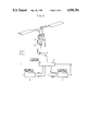
- FIG. 1 is an illustrative view showing a flight attitude of a helicopter.
- FIG. 2 is a view illustrating a control circuit according to the invention.
- FIG. 3 is a view illustrating another control circuit according to the invention.
- FIG. 4 is a graph showing step steering of a helicopter in the embodiment of the invention.
- a helicopter control comprises a vertical control effected by increasing and decreasing the rotor blade pitch, and a directional control effected by a torque effect resulting from the rotation of a rotor and a thrust of a tail rotor.
- horizontal control is effected by inclining the rotor disk (CD) of the main rotor in a desired direction relative to the mast axis (AG).
- control power The magnitude of inclined moment of the fuselage produced against a unit inclined angle of the rotor disk is called control power.
- ⁇ 0 Conning angle of the rotor blade
- Equation (1) gives
- ⁇ Angle between the mast axis (AG) and the vertical axis (YY)
- K is the control power value divided by the value of moment of inertia around the center of gravity (G) of the fuselage.
- Equation (6) giving attitude angle ⁇ response of the fuselage relative to the operating input ⁇ of a cyclic pitch control mechanism of the pilot is obtained
- Equation (6) shows that the operation performance of the helicopter is determined by the two factors of the rotor damping and control power.
- Equation (4) gives a input (proportional constant k 2 ) proportional to the angular velocity of the fuselage attitude angle ⁇ , and a input (proportional constant k 3 ) proportional to the angular acceleration of the fuselage attitude angle ⁇ .
- Equation (8) is obtained as the equation corresponding to Equation (6), ##EQU1##
- k 2 , k 3 should satisfy the following equation
- the fuselage attitude angle ⁇ response relative to the operating input ⁇ of the cyclic pitch control is, if limited to ⁇ , naturally the one shown by the fuselage having the rotor damping and control power value of T and K.
- Equation (4) gives
- Equation (13) is obtained as the equation corresponding to Equation (6),
- T T(1-k 3 K).
- Equation (4) gives
- Equation (15) is obtained as the equation corresponding to Equation (6)
- K K(1-k 2 T).
- the control mechanism according to the present invention may be provided in a control system which controls the actuator of the cyclic pitch control mechanism.
- arithmetic computers (5) are added to the control computer (4) so as to calculate k 3 ⁇ proportional to the angular acceleration of the fuselage attitude angle ⁇ , and k 2 ⁇ proportional to the angular velocity of the fuselage attitude angle ⁇ on the basis of the attitude angle input from a sensor (S), and to calculate correction input k 3 K.sub. ⁇ proportional the operating input ⁇ , and correction input -k 2 T.sub. ⁇ proportional to the operating input ⁇ on the basis of the cyclic pitch control input signal of the pilot, and by a desired control mode, to perform the cyclic pitch control by each following signal through the control computer (4), ##EQU2##
- values other than the above values may be suitably selected as the correction input proportional to the operating input ⁇ .
- various configurations can be applied such as obtaining the angular acceleration from the angular velocity gained by a rategyro, or inputting a signal gained by a known angular acceleration sensor to a desired actuator controller.
- the conventional SAS, etc. may be utilized to control by calculating and inputting only the correction signal.
- Equation (16) Equation corresponding to Equation (6)
- the fuselage attitude angle response relative to the operating input ⁇ of the cyclic pitch control is, if limited to ⁇ , naturally the one shown by the fuselage having the rotor damping and control power value of T and K. But when k 2 ⁇ and k 3 ⁇ are input in addition to ⁇ , it can be seen that ⁇ is changed completely and the same response as the one shown by the fuselage having the rotor damping and power control value different from T and K is exhibited.
- a 1 , A 2 , A 3 arbitrary constant.
- ⁇ 1 , ⁇ 2 , ⁇ 3 are roots of cubic equation
- the fuselage is shown to be converged rapidly to the desired final attitude angle .sub. ⁇ /-k 1 without producing any vibration, relative to the operating input ⁇ of the cyclic pitch control lever of the pilot.
- value k 1 showing the accuracy of automatic control is large enough, value .sub. ⁇ /-k 1 is almost zero and irrespective of .sub. ⁇ , the fuselage attitude angle ⁇ becomes zero, or the hovering attitude is retained.
- the active control of the present invention since the action of gust is same as that by the operating input .sub. ⁇ of the operating lever given by the pilot, under any gust of wind, the fuselage is always maintained hovering without any countermeasure taken by the pilot, thus the automatic control at hovering, which was difficult hitherto, is made possible.
- the active control of the present invention ensures the same automatic control in any control, besides the automatic hovering control described heretofore.
- the fuselage attitude angle always retains the assumed attitude angle ⁇ 0 input by the pilot under any external turbulence.
- the active control mechanism of the present invention may be provided in the control system controlling the actuator of the cyclic pitch control mechanism.
- arithmetic computers (5) are added to the control computer (4) so as to calculate k 3 ⁇ (proportional to the angular acceleration of the fuselage attitude angle ⁇ ) and k 2 ⁇ (proportional to the angular velocity of the fuselage attitude angle ⁇ ) on the basis of the attitude angle ⁇ input from a sensor (S), to compare the attitude angle ⁇ and the assumed attitude angle ⁇ 0 and calculate k 1 ( ⁇ - ⁇ o ) on the basis of the assumed attitude angle ⁇ 0 input from the sensor (S), and to perform the cyclic pitch control through the control computer (4) with each of above signals or
- a latest control system of a helicopter is mostly integrated with an automatic control mechanism into a combination with many kinds of inputs complicated mechanical and electrical circuits, resulting in such difficulties as securing the stability of the aircraft.
- a control mechanism controlling the actuator (3) which actuates the rod (2) coupled to the lower swash (1) by the control computer (4) it may be constructed to control the cyclic pitch through the control computer (4) by removing the arithmetic computer (5) shown, and using only the control computer (4) to calculate k 3 ⁇ (proportional to the angular acceleration and k 2 ⁇ (proportional to the angular velocity of the aircraft attitude angle ⁇ ) on the basis of attitude angle ⁇ input from the sensor (S), and adding them to the cyclic pitch control input ⁇ signal input of the pilot.
- the rotor damping and control power can be brought to their optimum values with simple construction and the excellent stability can be secured.
- the cyclic pitch control was performed by the computer simulation when k 3 ⁇ (proportional to the angular acceleration of the fuselage attitude angle ⁇ ) is 0 (one dot chain line). The result is shown in the step steering diagrams of FIG. 4.
- the present invention is very responsive as it takes only 0.5 to 1.0 second against 4 to 5 second required for the conventional SAS.
Abstract
The rotor damping and control power value can be made arbitrary by controlling a cyclic pitch control mechanism with a signal proportional to the angular acceleration of the attitude angle θ, a signal proportional to the angular velocity of the attitude angle θ, and a correction signal based upon the difference between the attitude angle θ and assumed attitude angle θ0, plus the cyclic pitch control input Ψ applied to a cyclic pitch lever of a pilot. Thus, the rotor damping and control power are brought to their optimum values in response to the actual flight conditions of a helicopter for ideal operability, resulting in both high stability and operability, and, for example, fully automatically controlled hovering can be accomplished without producing any vibration in the attitude angle control response.
Description
This application is a continuation of application Ser. No. 148,872, filed 1/27/88 now abandoned.
1. Field of the Invention
The present invention relates to an active control of a helicopter for the enhancement of stability, improvement of operation characteristics, reduction of vibration and an automatic control of hovering.
More particularly, the invention relates to an active control mechanism of the helicopter which is capable of changing the rotor damping and/or control power of the helicopter into the optimum values corresponding to the desired flight conditions, satisfying the contradictory characteristics of stability and quick mobility, and further, operating automatically at hovering and so on.
2. Description of the Prior Art
The operation control mechanism of a helicopter is basically unchanged since its invention, and the rotation of the rotor which is a matter of course is dominant in every respect.
That is to say, many benefits have occurred from its high degree of freedom in flight characteristics, while various problems have arisen in its dynamic instability and flight characteristics at hovering and low speed cruising due to the lack of means to maintain self-stability.
Also, the operability of the helicopter is said to be determined by the factors of control power and rotor damping, values which could be never improved particularly.
Conventionally, in order to increase the control power, a rigid rotor without a flapping hinge has been proposed, or for increasing the damping power, a so-called stabilizing bar and a servo-control rotor have been devised as disclosed, for example, in U.S. Pat. No. 3,050,276.
However, both techniques are still far from substantially solving such problems.
The helicopter was considered to be inherently unstable, thus forcing an excessive operating load on the pilot. Therefore, ever since the birth of helicopter, mechanical or electrical stabilizing mechanisms have been incorporated.
As a most popular electrical stabilizing mechanism, there is a stability augmentation system (SAS) wherein an actuator is arranged in a cyclic control rod or a main operating system in series, so that by an angular velocity signal of the inclined angle of a fuselage detected with various sensors, damping is given and controlled. Thereby, stability was believed to be enhanced, but the operability, in particular, a high mobility was yet to be satisfied at the same time.
Recently, due to changes in traffic and transporting conditions, the helicopter is required to have a high mobility and responsiveness in addition to a high stability.
Therefore, a control augmentation system (CAS) designed to provide both stability and operability, and a stability and control augmentation system (SCAS) combined with SAS have been developed to exclude the steering signal of the pilot from the SAS output.
Also, a device for obtaining the static stability is proposed to arrange the actuator in the operating system in series and actuate it as a function of the velocity or steering position.
Moreover, as to an attitude control, the difference between assumed and actual attitude angles of the fuselage is normally controlled by the feedback, and tending to be, together with the SAS, etc., integrated in an automatic operating mechanism, a so-called auto-pilot.
For example, U.S. Pat. No. 3,520,498 relates to "the stabilization of aircraft rotor systems having cyclic pitch, and more particularly to the generation of a signal representing rate of the change in the attitude of the rotor shaft relative to a first control axis for introducing cyclic pitch relative to a second control axis".
However, in either a conventional stability or a control augmentation system, the other mechanism is used together on the basis of SAS, resulting in a limited effect and a poor real time response corresponding to the changes of actual flight conditions, therefore the development of a more superior system and an operability which is variable in response to the desired flight conditions have been earnestly desired.
The present invention is, in view of the present situation aforementioned, directed to improve an active control of a helicopter by enhancement of stability, improvement of operation characteristics, reduction of vibration and an automatic control of hovering.
Moreover, the present invention is directed to an active control mechanism of the helicopter which is capable of changing its rotor damping and/or control power into optimum values in response to the desired flight conditions, satisfying the two contradictory characteristics of stability and quick movement, and operating automatically at hovering and so on.
According to the present invention, as a result of various studies made with respect to a cyclic pitch control mechanism which is able to change the rotor damping and/or control power, for the purpose of stability and control augmentation, and knowing the fact that the rotor damping can be brought to an arbitrary value by controlling with the angular acceleration of the attitude angle of the fuselage at cyclic pitch control, and that the characteristic value of the control power can be also made arbitrary by the cyclic pitch control performed together with the angular velocity of the fuselage attitude angle, the operation performance which satisfies the two contradictory characteristics of stability and quick movability was obtained. The active control mechanism of the helicopter which is capable of operating the hovering automatically was completed.
That is to say, according to the present invention, besides the operation control input Ψ added to the cyclic pitch control mechanism, by adding a signal proportional to the angular acceleration of the attitude angle θ or by further adding a correction signal proportional to the cyclic pitch control input Ψ to control the cyclic pitch control system, the rotor damping value can be made arbitrary and the operability can be changed arbitrarily.
Also, according to the present invention, besides the operation control input Ψ added to the cyclic pitch control mechanism, by controlling the cyclic pitch control system with a signal proportional to the angular velocity of the attitude angle θ and a correction signal proportional to the cyclic pitch control input Ψ, the control power can be brought to an arbitrary value.
Also, the present invention embodies the active control mechanism of the helicopter characterized in that, besides a cyclic pitch control input Ψ signal of the pilot, by adding a signal proportional to the angular acceleration of the attitude angle θ of the fuselage and a signal proportional to the angular velocity of the attitude angle θ of the fuselage, or by further adding a correction signal a (relative to the angular acceleration) proportional to the cyclic pitch control input Ψ and/or a correction signal b (relative to the angular velocity) proportional to the cyclic pitch control input Ψ, the actuator of the control mechanism is controlled for the cyclic pitch control.
Thus, according to the present invention, in response to the actual flight conditions of the helicopter, an optimum rotor damping value and/or control power value are determined for the ideal operability, enabling both high stability and good operability at the same time and providing helicopter which responds accurately in real time in response to the changes of actual flight conditions.
Moreover, according to the present invention, by controlling the cyclic pitch control mechanism with a signal proportional to the angular acceleration of the attitude angle θ, a signal proportional to the angular velocity of the attitude angle θ and a correction signal based upon the difference between the attitude angle θ and the assumed attitude angle θ0, the rotor damping value and the control power value can be made arbitrary.
Also, in response to the actual flight conditions of the helicopter, the optimum rotor damping value and control power value are determined for the ideal operability, enabling both high stability and good operability at the same time, for example, controlling the hovering fully automatically without producing any vibration in the attitude control response.
FIG. 1 is an illustrative view showing a flight attitude of a helicopter.
FIG. 2 is a view illustrating a control circuit according to the invention.
FIG. 3 is a view illustrating another control circuit according to the invention.
FIG. 4 is a graph showing step steering of a helicopter in the embodiment of the invention.
Reference characters in the drawings are as follows; G . . . Center of gravity of a helicopter, A . . . Center of a rotor boss metal, X--X . . . Ground level, Y--Y . . . Vertical axis, AG . . . Mast axis, R . . . Tail rotor. 1 . . . Lower swash, 2 . . . Rod, 3 . . . Actuator, 4 . . . Control computer, 5 . . . Arithmetic computer.
A helicopter control comprises a vertical control effected by increasing and decreasing the rotor blade pitch, and a directional control effected by a torque effect resulting from the rotation of a rotor and a thrust of a tail rotor.
Furthermore, horizontal control is effected by inclining the rotor disk (CD) of the main rotor in a desired direction relative to the mast axis (AG).
The magnitude of inclined moment of the fuselage produced against a unit inclined angle of the rotor disk is called control power.
Also, since the rotor disk (CD) is delayed from the mast axis (AG) when the helicopter is inclined at a certain angular velocity, a so-called damping action is produced on the rotor and the magnitude of inclined angle of the rotor disk produced in the case of unit angular velocity is called rotor damping.
In general, the equation specifying the flapping motion of the rotor blade is given as,
1/8+1/8γΩβ+Ω.sup.2 β=Ω.sup.2 β.sub.0 (1)
where
β=Flapping angle of the rotor blade
β0 =Conning angle of the rotor blade
Ω=Angular velocity of the rotor
γ=Constant
Now, applying an external unit force cos Ωt. Equation (1) gives
β=β.sub.o +(θ+Ψ){1-e.sup.-(γΩ/16)t }sinΩt (2)
As shown in FIG. 1, when
θ=Angle between the mast axis (AG) and the vertical axis (YY)
Ψ=Inclined angle of the swash plate against the mast axis (AG),
and angle between the aerodynamic direction acting vertically on the rotor disk (CD) and the vertical axis (YY) is indicated as σ, and substituting β of Equation (2) by σ gives
σ=(θ+Ψ){1-e.sup.-(γΩ/16)t } (3)
The differential equation specifying σ is,
σ=T(θ+Ψ-σ) (4)
where, T=.sub.γ Ω/16 or reciprocal number of the rotor damping,
Meanwhile, from the Newton's law,
θ=K(σ-θ) (5)
Here, K is the control power value divided by the value of moment of inertia around the center of gravity (G) of the fuselage.
When eliminating σ from Equations (4) and (5), Equation (6) giving attitude angle θ response of the fuselage relative to the operating input Ψ of a cyclic pitch control mechanism of the pilot is obtained,
θ+Tθ+Kθ=KT.sub.Ψ (6)
Equation (6) shows that the operation performance of the helicopter is determined by the two factors of the rotor damping and control power.
Meanwhile, in addition to the operating input Ψ of the cyclic pitch control mechanism of the pilot, when a input (proportional constant k2) proportional to the angular velocity of the fuselage attitude angle θ, and a input (proportional constant k3) proportional to the angular acceleration of the fuselage attitude angle θ are input to the cyclic pitch control mechanism, Equation (4) gives
σ=T(θ+Ψ+k.sub.2 θ+k.sub.3 θ-σ) (7)
Now, eliminating o from Equations (7) and (5), Equation (8) is obtained as the equation corresponding to Equation (6), ##EQU1## Here, k2, k3 should satisfy the following equation,
(1-k.sub.3 K)×(1-k.sub.2 T)=1 (11)
In the above detailed analysis, when comparing Equations (6) and (8), the fuselage attitude angle θ response relative to the operating input Ψ of the cyclic pitch control is, if limited to Ω, naturally the one shown by the fuselage having the rotor damping and control power value of T and K.
However, when k2 θ and k3 θ are input in addition to Ψ, it can be seen that θ is changed completely and the same response just as the one shown by the fuselage having the rotor damping and control power value of T' and K', which are given by Equations (9) and (10) and different from T and K is exhibited.
In the foregoing, though specific conditions were assumed and for the simplicity, conditional equations specifying k2 and k3 were established, k2 and k3 may be, in effect, given any numerical value independently and the aforementioned result can be obtained at any flight condition.
That is to say, in addition to the operating input Ψ of the cyclic pitch control mechanism of the pilot, when k3 θ proportional to the angular acceleration of the fuselage attitude angle θ, and correction input -k3 K.sub.Ψ proportional to the operating input Ψ are input to the cyclic pitch control mechanism, Equation (4) gives
σ=T(θ+.sub.Ψ +k.sub.3 θ-k.sub.3 K.sub.Ψ -σ) (12)
Eliminating σ from Equations (12) and (5), Equation (13) is obtained as the equation corresponding to Equation (6),
θ+Tθ+Kθ=KT.sub.Ψ (13)
Here, T=T(1-k3 K).
As it will be clear, by such an operation, the response of the helicopter is changed completely into the one shown when T is changed into T' (K is invariant).
Meanwhile, similarly, in addition to the operating input Ψ of the cyclic pitch control mechanism of the pilot, when k2 θ(proportional to the angular velocity of the fuselage attitude angle)θ and correcting input -k2 T.sub.Ψ (proportional to the operating input) Ψ are input to the cyclic pitch control mechanism, Equation (4) gives
σ=K(θ+.sub.Ψ +k.sub.2 θ-k.sub.2 T.sub.Ψ -σ) (14)
Now, eliminating σ from Equations (14) and (5), Equation (15) is obtained as the equation corresponding to Equation (6)
θ+Tθ+Kθ=KT.sub.Ψ (15)
Here, K=K(1-k2 T).
As it will be clear, by such an operation, the response of the helicopter is changed completely into the one shown when K is changed into K' (T is invariant).
The control mechanism according to the present invention may be provided in a control system which controls the actuator of the cyclic pitch control mechanism.
For example, as shown in FIG. 2, in the control mechanism wherein the actuator (3) actuating a rod (2) coupled to a lower swash (1) is controlled by a control computer (4), arithmetic computers (5) are added to the control computer (4) so as to calculate k3 θ proportional to the angular acceleration of the fuselage attitude angle θ, and k2 θ proportional to the angular velocity of the fuselage attitude angle θ on the basis of the attitude angle input from a sensor (S), and to calculate correction input k3 K.sub.Ψ proportional the operating input Ψ, and correction input -k2 T.sub.Ψ proportional to the operating input Ψ on the basis of the cyclic pitch control input signal of the pilot, and by a desired control mode, to perform the cyclic pitch control by each following signal through the control computer (4), ##EQU2## Also, values other than the above values may be suitably selected as the correction input proportional to the operating input Ψ.
In the present invention, when providing separately from the actuator control system of the cyclic pitch control mechanism, as a control system for controlling the actuator of the cyclic pitch control mechanism by a signal proportional to the angular acceleration of the fuselage attitude angle θ, various configurations can be applied such as obtaining the angular acceleration from the angular velocity gained by a rategyro, or inputting a signal gained by a known angular acceleration sensor to a desired actuator controller.
Also, as the control system for controlling the actuator of the cyclic pitch control mechanism by the signal k2 θ proportional to the angular velocity of the fuselage attitude angle θ and the correction signal -k2 T.sub.Ψ proportional to the cyclic pitch control input Ψ, the conventional SAS, etc. may be utilized to control by calculating and inputting only the correction signal.
Now, the cyclic pitch control mechanism whereby a fully automatically controlled hovering can be accomplished without producing vibration in the attitude angle control response will be described.
Eliminating σ from Equations (7) and (5) gives Equation (16) as the equation corresponding to Equation (6),
θ+T(1-k.sub.3 K)θ+K(1-k.sub.2 T)θ=KT.sub.Ψ(16)
In this analysis, when comparing the aforementioned Equation (6) and Equation (16), the fuselage attitude angle response relative to the operating input Ψ of the cyclic pitch control is, if limited to Ψ, naturally the one shown by the fuselage having the rotor damping and control power value of T and K. But when k2 θ and k3 θ are input in addition to Ψ, it can be seen that θ is changed completely and the same response as the one shown by the fuselage having the rotor damping and power control value different from T and K is exhibited.
Meanwhile, for the purpose of automatic control, if the input (proportional constant k1) proportional to the fuselage attitude angle is input, the equation corresponding to Equation (4) gives Equation (17) and that corresponding to Equation (6) gives Equation (18),
σ=T(θ+.sub.Ψ +k.sub.3 θ+k.sub.2 θ+k.sub.1 θ-σ) (17)
θ+T(1-k.sub.3 K)θ+(1-k.sub.2 T)Kθ-k.sub.1 TKθ=KT.sub.Ψ (18)
General solution of Equation (18) is given by,
θ=A.sub.1 e.sup.Λ 1.sup.t +A.sub.2 e.sup.Λ 2.sup.t +A.sub.3 e.sup.Λ 3t+.sub.Ψ /-k.sub.1 (19)
Here, A1, A2, A3 =arbitrary constant.
Λ1, Λ2, Λ3 are roots of cubic equation
Λ.sup.3 +T(1-k.sub.3 K)Λ.sup.2 +K(1-K(1-k.sub.2 T)Λ-k.sub.1 TK=0 (20)
As it will be clear from Equation (19), the fuselage is shown to be converged rapidly to the desired final attitude angle .sub.Ψ /-k1 without producing any vibration, relative to the operating input Ψ of the cyclic pitch control lever of the pilot.
In this case, however, it is limited to the case where discriminant of Equation (20) is negative, the response of θ is non-vibratory, and all three values of Λ1, Λ2, Λ3 are negatives with large absolute values.
Also, when value k1 showing the accuracy of automatic control is large enough, value .sub.Ψ /-k1 is almost zero and irrespective of .sub.Ψ, the fuselage attitude angle θ becomes zero, or the hovering attitude is retained.
Moreover, by the active control of the present invention, since the action of gust is same as that by the operating input .sub.Ψ of the operating lever given by the pilot, under any gust of wind, the fuselage is always maintained hovering without any countermeasure taken by the pilot, thus the automatic control at hovering, which was difficult hitherto, is made possible.
The automatic control is made possible, as described hereinbefore, only when the discriminant of Equation (20) is negative and the response of θ is non-vibratory, and all three values of λ1, λ2, λ3 are negatives with large absolute values.
This is not obtained if the inherent rotor damping and control power value of the helicopter are fixed, but is obtained only when these two values are changed into the desired specific values in a very narrow range in response to the desired flight conditions by the active control of the present invention.
The active control of the present invention ensures the same automatic control in any control, besides the automatic hovering control described heretofore.
For example, inputting k1 (θ-θo) in lieu of k1 θ to Equation (17), the fuselage attitude angle always retains the assumed attitude angle θ0 input by the pilot under any external turbulence.
The active control mechanism of the present invention may be provided in the control system controlling the actuator of the cyclic pitch control mechanism.
For example, as shown in FIG. 3, in the control mechanism wherein the actuator (3) actuating a rod (2) coupled to a lower swash (1) is controlled by a control computer (4), arithmetic computers (5) are added to the control computer (4) so as to calculate k3 θ (proportional to the angular acceleration of the fuselage attitude angle θ) and k2 θ(proportional to the angular velocity of the fuselage attitude angle θ) on the basis of the attitude angle θ input from a sensor (S), to compare the attitude angle θ and the assumed attitude angle θ0 and calculate k1 (θ-θo) on the basis of the assumed attitude angle θ0 input from the sensor (S), and to perform the cyclic pitch control through the control computer (4) with each of above signals or
.sub.Ψ, k.sub.3 θ, k.sub.2 θ, k.sub.1 (θ-θ.sub.o)
besides the cyclic pitch control input Ψ signal of the pilot.
As described hereinbefore, a latest control system of a helicopter is mostly integrated with an automatic control mechanism into a combination with many kinds of inputs complicated mechanical and electrical circuits, resulting in such difficulties as securing the stability of the aircraft.
However, it is a synthetic transmitting function indicating the aircraft attitude angle θ relative to the cyclic pitch control input Ψ added to a cyclic pitch lever of a pilot, which stabilizes the aircraft.
Since the coefficient of this function becomes rotor damping and control power function, in addition to the cyclic pitch control input Ψ signal of the pilot, by adding k3 θ (proportional to the angular acceleration), and k2 θ (proportional to the angular velocity of the aircraft attitude angle θ) to control the cyclic pitch control mechanism, rotor damping and control power can be brought to their optimum values, and thus the excellent stability of the aircraft can be secured.
More specifically, as shown in FIG. 2, in a control mechanism controlling the actuator (3) which actuates the rod (2) coupled to the lower swash (1) by the control computer (4), it may be constructed to control the cyclic pitch through the control computer (4) by removing the arithmetic computer (5) shown, and using only the control computer (4) to calculate k3 θ(proportional to the angular acceleration and k2 θ(proportional to the angular velocity of the aircraft attitude angle θ) on the basis of attitude angle θ input from the sensor (S), and adding them to the cyclic pitch control input Ψ signal input of the pilot. Thus the rotor damping and control power can be brought to their optimum values with simple construction and the excellent stability can be secured.
In each of above-mentioned embodiments, though only the case using one rotor has been described, it is to be understood that when using a plurality of rotors, by adding values of respective rotors, the same effect as each embodiment can be realized.
A real aircraft of 19,000 gross lbs. was utilized as a helicopter to obtain the time required to arrive at the desired attitude angle (θf =4°) when steering to change the attitude angle at the forward flight velocity of 120 knots (moment of steering was counted as 0 second).
At this time, two types of cyclic pitch control were performed, the one is by the conventional SAS (full line) and the other is by the control mechanism of the present invention (broken line).
Furthermore, for the purpose of comparison, in controlling the cyclic pitch with the control mechanism of the present invention, the cyclic pitch control was performed by the computer simulation when k3 θ (proportional to the angular acceleration of the fuselage attitude angle θ) is 0 (one dot chain line). The result is shown in the step steering diagrams of FIG. 4.
As it will be apparent from FIG. 4, it is to be understood that the present invention is very responsive as it takes only 0.5 to 1.0 second against 4 to 5 second required for the conventional SAS.
Also, in the case of the comparative sample, a vibration curve is so awful that the control is hardly possible, showing how important the angular acceleration input of the fuselage attitude angle θ is in the cyclic pitch control.
Claims (6)
1. In a cyclic pitch control mechanism of a helicopter, an active control mechanism having a lower swash plate, comprising:
an actuator of the control mechanism;
means for providing a cyclic pitch control signal input;
means for providing a first signal proportional to the angular acceleration of an attitude angle θ of the helicopter;
means for providing a second signal compensatory to said first signal and proportional to a cyclic pitch control signal input Ψ of a pilot;
means for providing a third signal of the cyclic pitch control signal input Ψ of a pilot; and
said means for providing a cyclic pitch control signal input being responsive to said first, second and third signals for controlling said actuator and swash plate.
2. In a cyclic pitch control mechanism of a helicopter, an active control mechanism having a lower swash plate, comprising:
an actuator of the control mechanism;
means for providing a cyclic pitch control signal input Ψ;
means for providing a first signal proportional to the angular velocity of an attitude angle θ of the helicopter;
means for providing a second signal compensatory to said first signal and proportional to a cyclic pitch control signal input Ψ of a pilot;
means for providing a third signal of the cyclic pitch control signal input Ψ of a pilot; and
said means for providing a cyclic pitch control signal input being responsive to said first, second and third signals for providing a control signal for controlling said swash plate and said actuator.
3. In a cyclic pitch control mechanism of a helicopter, an active control mechanism having a lower swash plate, comprising:
an actuator of the control mechanism;
means for providing a cyclic pitch control signal input Ψ;
means for providing first two signals proportional to the angular velocity of an attitude angle θ of the helicopter and proportional to the angular acceleration of the attitude angle θ;
means for providing second two signals compensatory to the angular velocity signal and angular acceleration signal and both proportional to a cyclic pitch control signal input Ψ of a pilot
means for providing a third signal of the cyclic pitch control input Ψ of a pilot; and
said means for providing a cyclic pitch control signal input being responsive to said first two signals, second two signals and said third signal for controlling said actuator and swash plate.
4. In a cyclic pitch control mechanism of a helicopter, an active control mechanism of the helicopter having a lower swash plate, comprising:
an actuator of the control mechanism;
means for providing a cyclic pitch control signal input Ψ;
means for providing first two signals proportional to the angular velocity of the attitude angle θ of the helicopter and proportional to the angular acceleration of the attitude angle θ;
means for providing a second signal proportional to the difference between the attitude angle θ and an assumed attitude angle θ0 ;
means for providing a third signal of the cyclic pitch control signal input Ψ of a pilot; and
said means for providing a cyclic pitch control signal input being responsive to said first two signals, said second signal and said third signal for controlling said actuator and swash plate.
5. In a cyclic pitch control mechanism of a helicopter,
an active control mechanism of the helicopter and having, a lower swash plate, comprising:
means for providing an attitude signal θ representing the attitude angle of the helicopter;
first processing means responsive to said attitude signal for generating a signal k2 θ proportional to the angular velocity of said attitude angle and a signal k3 θ proportional to the angular acceleration of said attitude angle;
second processing means responsive to the cyclic pitch control signal input Ψ from the pilot of the helicopter for generating a correction signal -k4 T Ψ and a correction signal -k5 K Ψ, where T is defined as the reciprocal number of rotor damping, K is defined as the control power value divided by the value moment of inertia around the center of gravity of the fuselage and k2, k3, k4 and k5 are constants;
a control computer responsive to signals k2 θ and k3 θ and correction signals -k4 T Ψ and -k5 K Ψ and the cyclic pitch control signal input Ψ from the pilot for generating a control signal; and
actuator means responsive to said control signal for controlling said lower swash plate.
6. In a cyclic pitch control mechanism of a helicopter,
an active control mechanism of the helicopter and having, a lower swash plate, comprising:
means for providing an attitude signal θ representing the attitude angle of the helicopter;
first processing means responsive to said attitude signal for producing a signal k2 θ proportional to the angular velocity of said attitude angle a signal k3 θ proportional to the angular acceleration of said attitude angle, where k2 and k3 are constants;
second processing means responsive to said attitude angle and an assumed attitude angle θo for producing a signal k1 (θ-θo);
a control computer responsive to said signals k2 θ and k3 θ and a cyclic pitch control signal input from the pilot of the helicopter and said signal k1 (θ-θo) for generating a control signal, where k1 is a constant; and
actuator means responsive to said control signal for controlling said lower swash plate.
Applications Claiming Priority (4)
| Application Number | Priority Date | Filing Date | Title |
|---|---|---|---|
| JP2278487A JPS63192697A (en) | 1987-02-03 | 1987-02-03 | Active control mechanism of helicopter |
| JP62-22784 | 1987-02-03 | ||
| JP2278587A JPS63192698A (en) | 1987-02-03 | 1987-02-03 | Active control mechanism of helicopter |
| JP62-22785 | 1987-02-03 |
Related Parent Applications (1)
| Application Number | Title | Priority Date | Filing Date |
|---|---|---|---|
| US07148872 Continuation | 1988-01-27 |
Publications (1)
| Publication Number | Publication Date |
|---|---|
| US4958786A true US4958786A (en) | 1990-09-25 |
Family
ID=26360045
Family Applications (1)
| Application Number | Title | Priority Date | Filing Date |
|---|---|---|---|
| US07/423,695 Expired - Fee Related US4958786A (en) | 1987-02-03 | 1989-10-18 | Active control mechanism for a helicopter |
Country Status (1)
| Country | Link |
|---|---|
| US (1) | US4958786A (en) |
Cited By (20)
| Publication number | Priority date | Publication date | Assignee | Title |
|---|---|---|---|---|
| US5316240A (en) * | 1991-08-29 | 1994-05-31 | Aerospatiale Societe Nationale Industrielle | Method and device for filtering the vibratory excitations transmitted between two parts especially between the rotor and the fuselage of a helicopter |
| US5405104A (en) * | 1993-01-04 | 1995-04-11 | Pande; John B. | Stopped rotor aircraft utilizing a flipped airfoil X-wing |
| EP0727350A1 (en) * | 1995-02-15 | 1996-08-21 | Bruno Ziegler | Rotorcraft with gyroscopic rotor stabilisation |
| US5799901A (en) * | 1995-12-06 | 1998-09-01 | Mcdonnell Douglas Helicopter Co. | Rotor blade swashplate-axis rotation and gyroscopic moments compensator |
| US5860807A (en) * | 1996-04-22 | 1999-01-19 | The United States Of America As Represented By The National Aeronautics And Space Administration | System and method for finite element simulation of helicopter turbulence |
| US6254037B1 (en) | 1999-08-06 | 2001-07-03 | Bell Helicopter Textron Inc. | Variable gradient control stick force feel adjustment system |
| WO2002093283A1 (en) * | 2001-05-15 | 2002-11-21 | Bernard De Salaberry | Control steering device for vertical-takeoff aircraft |
| US6533549B1 (en) * | 1999-03-10 | 2003-03-18 | Zf Luftfahrttechnik Gmbh | Helicopter |
| US20090047861A1 (en) * | 2006-01-19 | 2009-02-19 | Silverlit Toys Manufactory Ltd. | Remote controlled toy helicopter |
| US20100022157A1 (en) * | 2006-01-19 | 2010-01-28 | Silverlit Toys Manufactory Ltd. | Helicopter |
| US20100023186A1 (en) * | 2007-07-02 | 2010-01-28 | Vineet Sahasrabudhe | Fly-by-wire flight control system with electronic lead/lag damper algorithm |
| US7662013B2 (en) * | 2006-01-19 | 2010-02-16 | Silverlit Toys Manufactory Ltd. | Helicopter with horizontal control |
| WO2011000146A1 (en) * | 2009-06-30 | 2011-01-06 | Tian Yu | Remote-control model helicopter |
| US8002604B2 (en) * | 2006-01-19 | 2011-08-23 | Silverlit Limited | Remote controlled toy helicopter |
| CN101869769B (en) * | 2008-04-21 | 2012-05-23 | 上海九鹰电子科技有限公司 | Mechanical maneuvering system of single-rotor wing model helicopter |
| CN104843183A (en) * | 2015-04-01 | 2015-08-19 | 天峋创新(北京)科技有限公司 | Tail rotor pitch structure of unmanned helicopter |
| US9266608B2 (en) | 2013-03-18 | 2016-02-23 | Sikorsky Aircraft Corporation | Compensating for lead-lag in rotor system |
| CN106553768A (en) * | 2016-11-30 | 2017-04-05 | 中国直升机设计研究所 | A kind of main oar steering wheel benchmark method of adjustment |
| CN108100234A (en) * | 2017-12-03 | 2018-06-01 | 中国直升机设计研究所 | A kind of helicopter tail rotor servo actuator benchmark method of adjustment |
| CN108495789A (en) * | 2017-05-23 | 2018-09-04 | 深圳市大疆创新科技有限公司 | Installation error detection method, equipment and the unmanned plane of accelerometer |
Citations (5)
| Publication number | Priority date | Publication date | Assignee | Title |
|---|---|---|---|---|
| US3010679A (en) * | 1957-03-04 | 1961-11-28 | Bell Aerospace Corp | Dephased accelerometer |
| US3050276A (en) * | 1958-09-02 | 1962-08-21 | United Aircraft Corp | Automatic stabilization device |
| US3429376A (en) * | 1966-10-18 | 1969-02-25 | Kurt H Hohenemser | Automatic control system for aircraft lifting rotor |
| US3520498A (en) * | 1967-12-20 | 1970-07-14 | Bell Aerospace Corp | Stabilization of aircraft rotors having cyclic pitch |
| US4834318A (en) * | 1986-12-15 | 1989-05-30 | Westland Group Plc | Helicopter flight control systems |
-
1989
- 1989-10-18 US US07/423,695 patent/US4958786A/en not_active Expired - Fee Related
Patent Citations (5)
| Publication number | Priority date | Publication date | Assignee | Title |
|---|---|---|---|---|
| US3010679A (en) * | 1957-03-04 | 1961-11-28 | Bell Aerospace Corp | Dephased accelerometer |
| US3050276A (en) * | 1958-09-02 | 1962-08-21 | United Aircraft Corp | Automatic stabilization device |
| US3429376A (en) * | 1966-10-18 | 1969-02-25 | Kurt H Hohenemser | Automatic control system for aircraft lifting rotor |
| US3520498A (en) * | 1967-12-20 | 1970-07-14 | Bell Aerospace Corp | Stabilization of aircraft rotors having cyclic pitch |
| US4834318A (en) * | 1986-12-15 | 1989-05-30 | Westland Group Plc | Helicopter flight control systems |
Cited By (25)
| Publication number | Priority date | Publication date | Assignee | Title |
|---|---|---|---|---|
| US5316240A (en) * | 1991-08-29 | 1994-05-31 | Aerospatiale Societe Nationale Industrielle | Method and device for filtering the vibratory excitations transmitted between two parts especially between the rotor and the fuselage of a helicopter |
| US5405104A (en) * | 1993-01-04 | 1995-04-11 | Pande; John B. | Stopped rotor aircraft utilizing a flipped airfoil X-wing |
| EP0727350A1 (en) * | 1995-02-15 | 1996-08-21 | Bruno Ziegler | Rotorcraft with gyroscopic rotor stabilisation |
| US5799901A (en) * | 1995-12-06 | 1998-09-01 | Mcdonnell Douglas Helicopter Co. | Rotor blade swashplate-axis rotation and gyroscopic moments compensator |
| US5860807A (en) * | 1996-04-22 | 1999-01-19 | The United States Of America As Represented By The National Aeronautics And Space Administration | System and method for finite element simulation of helicopter turbulence |
| US6533549B1 (en) * | 1999-03-10 | 2003-03-18 | Zf Luftfahrttechnik Gmbh | Helicopter |
| US6254037B1 (en) | 1999-08-06 | 2001-07-03 | Bell Helicopter Textron Inc. | Variable gradient control stick force feel adjustment system |
| WO2002093283A1 (en) * | 2001-05-15 | 2002-11-21 | Bernard De Salaberry | Control steering device for vertical-takeoff aircraft |
| FR2824924A1 (en) * | 2001-05-15 | 2002-11-22 | Salaberry Bernard Lucien Ch De | Steering system for vertical take-off aircraft includes two contra-rotating propellers with axis adjustable to control steering direction |
| US7662013B2 (en) * | 2006-01-19 | 2010-02-16 | Silverlit Toys Manufactory Ltd. | Helicopter with horizontal control |
| US20090047861A1 (en) * | 2006-01-19 | 2009-02-19 | Silverlit Toys Manufactory Ltd. | Remote controlled toy helicopter |
| US20100022157A1 (en) * | 2006-01-19 | 2010-01-28 | Silverlit Toys Manufactory Ltd. | Helicopter |
| US8002604B2 (en) * | 2006-01-19 | 2011-08-23 | Silverlit Limited | Remote controlled toy helicopter |
| US8357023B2 (en) * | 2006-01-19 | 2013-01-22 | Silverlit Limited | Helicopter |
| US8548648B2 (en) * | 2007-07-02 | 2013-10-01 | Sikorsky Aircraft Corporation | Fly-by-wire flight control system with electronic lead/lag damper algorithm |
| US20100023186A1 (en) * | 2007-07-02 | 2010-01-28 | Vineet Sahasrabudhe | Fly-by-wire flight control system with electronic lead/lag damper algorithm |
| CN101869769B (en) * | 2008-04-21 | 2012-05-23 | 上海九鹰电子科技有限公司 | Mechanical maneuvering system of single-rotor wing model helicopter |
| WO2011000146A1 (en) * | 2009-06-30 | 2011-01-06 | Tian Yu | Remote-control model helicopter |
| US9266608B2 (en) | 2013-03-18 | 2016-02-23 | Sikorsky Aircraft Corporation | Compensating for lead-lag in rotor system |
| CN104843183A (en) * | 2015-04-01 | 2015-08-19 | 天峋创新(北京)科技有限公司 | Tail rotor pitch structure of unmanned helicopter |
| CN106553768A (en) * | 2016-11-30 | 2017-04-05 | 中国直升机设计研究所 | A kind of main oar steering wheel benchmark method of adjustment |
| CN106553768B (en) * | 2016-11-30 | 2018-10-02 | 中国直升机设计研究所 | A kind of main paddle steering engine benchmark method of adjustment |
| CN108495789A (en) * | 2017-05-23 | 2018-09-04 | 深圳市大疆创新科技有限公司 | Installation error detection method, equipment and the unmanned plane of accelerometer |
| WO2018214014A1 (en) * | 2017-05-23 | 2018-11-29 | 深圳市大疆创新科技有限公司 | Method and device for measuring mounting error of accelerometer, and unmanned aerial vehicle |
| CN108100234A (en) * | 2017-12-03 | 2018-06-01 | 中国直升机设计研究所 | A kind of helicopter tail rotor servo actuator benchmark method of adjustment |
Similar Documents
| Publication | Publication Date | Title |
|---|---|---|
| US4958786A (en) | Active control mechanism for a helicopter | |
| US4025230A (en) | Advanced control system for a rotor and/or a compound or rotary wing vehicle | |
| US6246929B1 (en) | Enhanced stall and recovery control system | |
| RU2086476C1 (en) | Helicopter with one main rotor and method of compensation of contra-rotating torque of main rotor of single-rotor helicopter | |
| US4168045A (en) | Speed and collective pitch bias of helicopter longitudinal cyclic pitch | |
| US5001646A (en) | Automated helicopter flight control system | |
| US4723214A (en) | Automatic camber control | |
| US6053452A (en) | Compensation apparatus for main rotor torque | |
| US4411595A (en) | Control system for gas turbine engine | |
| JP3420764B2 (en) | Improved model following control system | |
| US11634209B2 (en) | Method for controlling at least one aerodynamic stabilizer member of a hybrid helicopter, and a hybrid helicopter | |
| US11312480B2 (en) | System and method for controlling rotorcraft | |
| GB2131979A (en) | Estimator means for a gas turbine powered helicopter | |
| EP0115401B1 (en) | Airspeed control for aircraft | |
| US5676334A (en) | Cyclic minimizer through alignment of the center of gravity and direction of flight vectors | |
| CN111498095A (en) | System and method for controlling a rotorcraft | |
| US6622065B2 (en) | Flight control device for an aircraft, in particular for a helicopter | |
| EP0290532B1 (en) | Synthetic speed stability flight control system | |
| US6290171B1 (en) | Device for controlling a helicopter hybrid countertorque system | |
| US3095169A (en) | Flight path control system | |
| IL72461A (en) | Rotorcraft load factor enhancer | |
| US2948494A (en) | Control systems for dirigible craft | |
| Stapleford | An analytical study of v/stol handling qualities in hover and transition | |
| JPH06293295A (en) | Piloting device | |
| JPS63192698A (en) | Active control mechanism of helicopter |
Legal Events
| Date | Code | Title | Description |
|---|---|---|---|
| FPAY | Fee payment |
Year of fee payment: 4 |
|
| REMI | Maintenance fee reminder mailed | ||
| LAPS | Lapse for failure to pay maintenance fees | ||
| FP | Lapsed due to failure to pay maintenance fee |
Effective date: 19980925 |
|
| STCH | Information on status: patent discontinuation |
Free format text: PATENT EXPIRED DUE TO NONPAYMENT OF MAINTENANCE FEES UNDER 37 CFR 1.362 |