US4960630A - Apparatus for producing symmetrical fluid entangled non-woven fabrics and related method - Google Patents
Apparatus for producing symmetrical fluid entangled non-woven fabrics and related method Download PDFInfo
- Publication number
- US4960630A US4960630A US07/181,284 US18128488A US4960630A US 4960630 A US4960630 A US 4960630A US 18128488 A US18128488 A US 18128488A US 4960630 A US4960630 A US 4960630A
- Authority
- US
- United States
- Prior art keywords
- web
- entangling
- curtain
- fibers
- set forth
- Prior art date
- Legal status (The legal status is an assumption and is not a legal conclusion. Google has not performed a legal analysis and makes no representation as to the accuracy of the status listed.)
- Expired - Lifetime
Links
Images


Classifications
-
- D—TEXTILES; PAPER
- D04—BRAIDING; LACE-MAKING; KNITTING; TRIMMINGS; NON-WOVEN FABRICS
- D04H—MAKING TEXTILE FABRICS, e.g. FROM FIBRES OR FILAMENTARY MATERIAL; FABRICS MADE BY SUCH PROCESSES OR APPARATUS, e.g. FELTS, NON-WOVEN FABRICS; COTTON-WOOL; WADDING ; NON-WOVEN FABRICS FROM STAPLE FIBRES, FILAMENTS OR YARNS, BONDED WITH AT LEAST ONE WEB-LIKE MATERIAL DURING THEIR CONSOLIDATION
- D04H1/00—Non-woven fabrics formed wholly or mainly of staple fibres or like relatively short fibres
- D04H1/40—Non-woven fabrics formed wholly or mainly of staple fibres or like relatively short fibres from fleeces or layers composed of fibres without existing or potential cohesive properties
- D04H1/44—Non-woven fabrics formed wholly or mainly of staple fibres or like relatively short fibres from fleeces or layers composed of fibres without existing or potential cohesive properties the fleeces or layers being consolidated by mechanical means, e.g. by rolling
-
- B—PERFORMING OPERATIONS; TRANSPORTING
- B29—WORKING OF PLASTICS; WORKING OF SUBSTANCES IN A PLASTIC STATE IN GENERAL
- B29C—SHAPING OR JOINING OF PLASTICS; SHAPING OF MATERIAL IN A PLASTIC STATE, NOT OTHERWISE PROVIDED FOR; AFTER-TREATMENT OF THE SHAPED PRODUCTS, e.g. REPAIRING
- B29C59/00—Surface shaping of articles, e.g. embossing; Apparatus therefor
- B29C59/02—Surface shaping of articles, e.g. embossing; Apparatus therefor by mechanical means, e.g. pressing
-
- D—TEXTILES; PAPER
- D04—BRAIDING; LACE-MAKING; KNITTING; TRIMMINGS; NON-WOVEN FABRICS
- D04H—MAKING TEXTILE FABRICS, e.g. FROM FIBRES OR FILAMENTARY MATERIAL; FABRICS MADE BY SUCH PROCESSES OR APPARATUS, e.g. FELTS, NON-WOVEN FABRICS; COTTON-WOOL; WADDING ; NON-WOVEN FABRICS FROM STAPLE FIBRES, FILAMENTS OR YARNS, BONDED WITH AT LEAST ONE WEB-LIKE MATERIAL DURING THEIR CONSOLIDATION
- D04H1/00—Non-woven fabrics formed wholly or mainly of staple fibres or like relatively short fibres
- D04H1/40—Non-woven fabrics formed wholly or mainly of staple fibres or like relatively short fibres from fleeces or layers composed of fibres without existing or potential cohesive properties
- D04H1/44—Non-woven fabrics formed wholly or mainly of staple fibres or like relatively short fibres from fleeces or layers composed of fibres without existing or potential cohesive properties the fleeces or layers being consolidated by mechanical means, e.g. by rolling
- D04H1/46—Non-woven fabrics formed wholly or mainly of staple fibres or like relatively short fibres from fleeces or layers composed of fibres without existing or potential cohesive properties the fleeces or layers being consolidated by mechanical means, e.g. by rolling by needling or like operations to cause entanglement of fibres
- D04H1/492—Non-woven fabrics formed wholly or mainly of staple fibres or like relatively short fibres from fleeces or layers composed of fibres without existing or potential cohesive properties the fleeces or layers being consolidated by mechanical means, e.g. by rolling by needling or like operations to cause entanglement of fibres by fluid jet
- D04H1/495—Non-woven fabrics formed wholly or mainly of staple fibres or like relatively short fibres from fleeces or layers composed of fibres without existing or potential cohesive properties the fleeces or layers being consolidated by mechanical means, e.g. by rolling by needling or like operations to cause entanglement of fibres by fluid jet for formation of patterns, e.g. drilling or rearrangement
-
- D—TEXTILES; PAPER
- D04—BRAIDING; LACE-MAKING; KNITTING; TRIMMINGS; NON-WOVEN FABRICS
- D04H—MAKING TEXTILE FABRICS, e.g. FROM FIBRES OR FILAMENTARY MATERIAL; FABRICS MADE BY SUCH PROCESSES OR APPARATUS, e.g. FELTS, NON-WOVEN FABRICS; COTTON-WOOL; WADDING ; NON-WOVEN FABRICS FROM STAPLE FIBRES, FILAMENTS OR YARNS, BONDED WITH AT LEAST ONE WEB-LIKE MATERIAL DURING THEIR CONSOLIDATION
- D04H18/00—Needling machines
- D04H18/04—Needling machines with water jets
-
- D—TEXTILES; PAPER
- D06—TREATMENT OF TEXTILES OR THE LIKE; LAUNDERING; FLEXIBLE MATERIALS NOT OTHERWISE PROVIDED FOR
- D06C—FINISHING, DRESSING, TENTERING OR STRETCHING TEXTILE FABRICS
- D06C23/00—Making patterns or designs on fabrics
-
- B—PERFORMING OPERATIONS; TRANSPORTING
- B29—WORKING OF PLASTICS; WORKING OF SUBSTANCES IN A PLASTIC STATE IN GENERAL
- B29K—INDEXING SCHEME ASSOCIATED WITH SUBCLASSES B29B, B29C OR B29D, RELATING TO MOULDING MATERIALS OR TO MATERIALS FOR MOULDS, REINFORCEMENTS, FILLERS OR PREFORMED PARTS, e.g. INSERTS
- B29K2313/00—Use of textile products or fabrics as reinforcement
-
- Y—GENERAL TAGGING OF NEW TECHNOLOGICAL DEVELOPMENTS; GENERAL TAGGING OF CROSS-SECTIONAL TECHNOLOGIES SPANNING OVER SEVERAL SECTIONS OF THE IPC; TECHNICAL SUBJECTS COVERED BY FORMER USPC CROSS-REFERENCE ART COLLECTIONS [XRACs] AND DIGESTS
- Y10—TECHNICAL SUBJECTS COVERED BY FORMER USPC
- Y10T—TECHNICAL SUBJECTS COVERED BY FORMER US CLASSIFICATION
- Y10T428/00—Stock material or miscellaneous articles
- Y10T428/24—Structurally defined web or sheet [e.g., overall dimension, etc.]
- Y10T428/24273—Structurally defined web or sheet [e.g., overall dimension, etc.] including aperture
-
- Y—GENERAL TAGGING OF NEW TECHNOLOGICAL DEVELOPMENTS; GENERAL TAGGING OF CROSS-SECTIONAL TECHNOLOGIES SPANNING OVER SEVERAL SECTIONS OF THE IPC; TECHNICAL SUBJECTS COVERED BY FORMER USPC CROSS-REFERENCE ART COLLECTIONS [XRACs] AND DIGESTS
- Y10—TECHNICAL SUBJECTS COVERED BY FORMER USPC
- Y10T—TECHNICAL SUBJECTS COVERED BY FORMER US CLASSIFICATION
- Y10T442/00—Fabric [woven, knitted, or nonwoven textile or cloth, etc.]
- Y10T442/60—Nonwoven fabric [i.e., nonwoven strand or fiber material]
- Y10T442/689—Hydroentangled nonwoven fabric
Definitions
- This invention generally relates to an apparatus for use in-line with carding apparatus for entangling a non-woven web. More particularly, it is concerned with a divergent jet fluid entangling apparatus and related process which precisely orient fibers in a non-woven web into prescribed patterns without requirement of complex filtration, scrambler and air lay systems of the prior art.
- Non-woven fabrics produced by the method of the invention have a patterned symmetrical structure with machine and cross-direction ("MD/CD”) randomization ratios in the range of 1:1-4:1 and corresponding MD/CD tensile strengths.
- non-woven fibers are treated with high pressure fluids while supported on apertured patterning screens.
- the patterning screen is provided on a drum or continuous conveyor which traverses pressurized fluid jets. Entanglement is effected by employing columnar jet streams which entangle fibers in the web into ordered groups and configurations corresponding to the aperture array in the patterning screen.
- Non-woven fabrics having MD and CD tensile strengths and randomized structures are produced by action of the jet streams which cause fibers in the web to migrate to apertured or void areas in the screen, entangle and intertwine.
- carded web may be randomized by scrambling and air lay systems prior to entangling.
- Vacuum and screen baffling systems of the prior art introduce machine complexity and associated tooling costs.
- Top screens lower energy efficiency of the entangling process by reducing the energy flux of fluids which impinge upon the web, restricting movement of the fibers. See U.S. Pat. No. 2,862,251 to F. Kalwaites.
- the present invention is directed to a fluid entangling process and related apparatus for producing novel non-woven fabrics without requirement of the complex machinery of the prior art.
- the present invention employs pressurized fan jets with wide diameter outlet orifices to direct divergent fluid sprays to non-randomized fibrous webs.
- the divergent jets coact with specially configured forming members which support the web.
- Wide diameter divergent jet nozzles employed in the invention facilitate recirculation of jet streams without requirement of complex filtration systems.
- a more specific object of the invention is to provide hydroentangling apparatus which is mechanically less complex than employed in prior art processes.
- a further object of the invention is to provide a hydroentangling apparatus and process which produce non-woven fabrics having symmetrical structures and MD/CD randomization ratios in the range of 1:1-4:1.
- a still further object of the invention is to produce non-wovens having improved tensile strength characteristics employing apparatus and processes which are less complex as compared to the prior art.
- an apparatus and related process for entangling a staple, non-randomized fibrous web which employs divergent fluid jets to randomize and entangle web fibers.
- the web is advanced through an entangling station on a conveying means which supports an entangling member or forming screen having a symmetrical pattern of fluid pervious void areas.
- Divergent jet sprays which are disposed above the entangling member direct a continuous curtain of fluid onto the web, coacting with the entangling member to precisely orient the fiber structure and entangle the web fibers into a coherent lattice structure.
- control means which includes a baffle plate and coacting means for directing an air curtain to the web at an entry area of the entangling station.
- the control means also includes a generally hollow perforated cylindrical roll disposed for frictional rotatable movement on the web at a terminal end area of the entangling station.
- a plurality of divergent jet nozzles are mounted on closely packed cross-directionally aligned spaced manifolds. Divergent jets oriented in the CD are provided with angles of divergence in the range of 2 to 30 degrees, and located within 3 to 6 inches from the entangling member. Pressure is preferably ramped in the MD from manifold to manifold over a pressure range of 200-1100 psi to impart energy to the web of approximately 1.0 hp-hr/lb of fabric.
- an entangling member which has a symmetrical pattern of void areas which correspond to preferred fabric patterns.
- the void areas preferably occupy at least 25 per cent of the entangling member area.
- Improved MD and/or CD tensile strengths are obtained by void patterns having varying MD/CD configurations.
- the preferred pattern includes a plurality of apertures arranged so that the spacing ratio of MD apertures is greater than CD apertures. This pattern yields a novel fabric pattern in which an array of dense nodes are connected by a diamond shaped pattern of interstitial fibers.
- the apparatus and related method of the invention advance the art by use of a divergent jet system which is less complex and precision demanding than hydroentangling systems of the prior art.
- Divergent jet nozzles employed in the invention have wide orifice diameters as compared to prior art columnar jet systems and, accordingly, do not require the exacting filtration systems of the prior art. Fiber debris contained in fluid recirculated to the divergent jet nozzles in the entangling process pass through the wide diameter orifices without clogging as is prevalent in prior art columnar systems which have small diameter orifices.
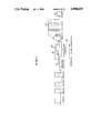
- FIG. 1 is a schematic view of a production line including an entangling station in accordance with the invention for the continuous production of symmetrical hydroentangled non-woven fabrics;
- FIG. 2 is a schematic illustration of the hydroentangling process of the invention
- FIG. 3 is an isometric view of the apparatus represented by the hydroentangling entangling station of FIG. 1 showing the manner in which carded web is advanced through an entangling jet fluid curtain supported on a generally planar conveyor and fabric entangling and forming member;
- FIG. 4 is a cross-section of the entangling apparatus of FIG. 3 which also includes a schematic illustration of a pumping and filtration system employed in the invention
- FIG. 5 is a cross-section of an alternative embodiment of the hydroentangling apparatus in which an entangling member having a cylindrical configuration is substituted for the generally planar conveyor and fabric forming member of FIG. 3;
- FIG. 6A is a plan view of MD aligned carded web overlying an apertured fabric forming member prior to entanglement of web fibers, the forming screen having an aperture pattern including a larger spacing ratio between MD than CD apertures;
- FIG. 6B illustrates the entangled fiber pattern formed on the screen of FIG. 6A employing the hydroentangling apparatus and process of the invention
- FIG. 7 is an illustration similar to FIG. 6B in which the forming member has an aperture pattern including a larger spacing ratio between CD than MD apertures;
- FIG. 8 illustrates an alternative woven entangling member weave structured non-woven fabric produced in accordance with the apparatus and process of the invention
- FIG. 9 is a cross-section of an alternative entangling apparatus embodiment, similar to FIG. 4, in which baffles are arranged in proximity to the web between spaced manifolds;
- FIGS. 1OA and B are photographs at 1O ⁇ magnification of a hydroentangled non-woven cotton fabric produced as disclosed in Example 1 on the apertured entangling member illustrated in FIGS. 6A and 6B;
- FIGS. 11A and B are photographs at 10 ⁇ magnification of a hydroentangled non-woven cotton fabric produced as disclosed in Example 3 on the apertured entangling member illustrated in FIG. 7;
- FIG. 12 is a photograph at 1.8 ⁇ magnification of a hydroentangled non-woven cotton fabric produced as disclosed in Example 4 on a planar fine mesh reverse dutch woven screen (not illustrated);
- FIG. 13 is a photograph at 1.8 ⁇ magnification of a hydroentangled non-woven cotton fabric produced as disclosed in Example 5 on a planar mesh reverse dutch screen (not illustrated);
- FIG. 14 is a photograph at 1.8 ⁇ magnification of a hydroentangled non-woven cotton fabric produced as disclosed in Example 6 on a planar woven screen overlaid with a hexagonal screen (not illustrated);
- FIG. 15 is a photograph at 10 ⁇ magnification of a hydroentangled non-woven cotton fabric produced as disclosed in Examples 7 and 8 on the woven forming screen illustrated in FIG. 8.
- FIG. 1 a view of preferred embodiment of the entangling apparatus 10 is shown in FIG. 1 situated at the output end of a series of conventional carding apparatus C1-C4.
- the apparatus 10 provides a system for entangling non-woven fibrous materials by a novel fluid entangling process. Particular advantage is obtained when the entangling process of the invention is applied to a non-randomized fibrous web 12.
- FIG. 1 illustrates a preferred application of the apparatus 10 in-line with conventional carding apparatus C1-C4 which output machine direction ("MD") oriented carded web to a peeler roller (not shown) and inclined conveyor 14 for processing in the apparatus of the invention.
- MD machine direction
- water is employed to hydroentangle and randomize the fibers in the carded web 12 in an entangling station 16 in a manner to be hereinafter described.
- the web is conveyed to a conventional padder 18 and dry can 20 apparatus to provide a finished non-woven fabric for stock rolling on a winder 22.
- this unit includes an endless conveyor means for advancing the non-randomized web through the entangling station 16.
- the conveyor means includes an entangling member 24 which is supported on rollers 26, 28 and drive means (not shown) for rotation of the rollers.
- Preferred line speeds for the conveyor are in the range of 30 to 500 ft/min.
- the entangling member 24 which preferably has a planar configuration, includes a symmetrical pattern of void areas which are fluid pervious and define an entangling pattern for the fibrous web 12.
- the void areas occupy at least 25 per cent of the area of the entangling member 24.
- the entangling member may be provided with a variety of patterns which produce distinct novel fabrics. Representative entangling members are illustrated in FIGS. 6A, 7, and 8.
- each manifold 30 includes a plurality of closely aligned and spaced divergent jet nozzles 32.
- Preferred manifolds have specifications designed to deliver fluid pressures to the nozzles in the range of 200 to 2500 psi. Advantage in the entangling process is obtained by ramping the manifold pressure in the MD so that increased fluid flows impinge the web as its lattice structure and coherence develop.
- the nozzles are spaced approximately 1 inch apart on the manifolds which in turn are positioned 3 to 6 inches above the entangling member 24.
- the nozzles 32 eject sprays 34 having a divergent fan shaped configuration downwardly onto the web 12 as it is advanced through the entangling apparatus.
- the close packed manifold arrangement and spacing of the nozzles 32 define a curtain of fluid which continuously impinges upon the web 12 and coacts with the entangling member 24.
- the jet sprays 34 diverge in the CD relative to a central nozzle axis 36 which is perpendicular to the web.
- a divergence angle of approximately 18 degrees yields optimum entanglement and randomization of the web.
- the curtain fluid must output energy to the web 12 of at least 0.1 hp-hr/lb and preferably in the range of 0.4-2.0 Hp-hr/lb.
- Preferred nozzles 32 for use in the invention are of the type manufactured by Spraying Systems Co., distributed by J. W. Sowden & Associates, P.0. Box 5046, Manchester, N.H. 03108, under product designation 0503-TC.
- This nozzle has a tungsten carbide spray tip which has been found effective for providing regulated pressure sprays.
- Ejection orifices in the nozzle have a non-circular shaped configurations.
- the preferred nozzle has an effective diameter of 0.043 inches and flow of 1.5 gallons/min at an air included jet spray angle of 18° and 1000 psi.
- Air entrained by the divergent jet sprays 34 is deflected by the web 12 generating turbulence which lifts the web relative to the entangling member and results in blistering of the web and fabric irregularities.
- a control means is provided which includes stabilizing mechanisms at entry and terminal end areas 38, 40 of the entangling station.
- an air curtain means for directing air to the web 12 may be provided to coact with a baffle plate 42 which extends from a position outboard of the fluid curtain upwardly on an angle into the curtain. See FIGS. 3 and 4.
- the air curtain means includes an air nozzle 44 which directs a continuous curtain of air beneath the baffle 42 to control entrained air in the entry area 38 of the entangling station 16.
- a generally hollow perforated cylindrical roll 46 is spaced above the web 12. Counterclockwise rotation of the roll 46 by a friction drive means dissipates air entrained by the air curtain. Frictional movement of the roll 46 over the web 12 also presses fluid from the web through the entangling member 24.
- the continuous curtain of aqueous fluid counterbalances the effect of entrained air when the manifolds 30 are arranged in close proximity, e.g., spacing of approximately 3 to 4.5 inches, as illustrated in FIG. 4.
- baffle members 48 are spaced from the web. See FIG. 9.
- Baffle members 48 have a generally V-shaped configuration to shield the web 12 from the effects of entrained air. Further advantage can be obtained by perforating the baffle members 48 to enable entrained air to escape.
- the manifolds 30 are spaced approximately 7 inches apart and the baffles 48 extend in the CD of the web.
- a collecting tank 50 is located below the entangling member 24 for receiving fluids employed in the entangling process.
- the collecting tank 50 directs fluids to a filter 52 which removes fiber debris, and a pump 54 for recirculation of fluid to the manifolds 30.
- Pressure regulators 56 are located on a manifold connecting line 58 to provide controlled nozzle 32 pressures and transfer of energy to the web 12.
- FIG. 5 An alternative conveyor means structure is illustrated in FIG. 5 which includes a cylindrical entangling member 60.
- this embodiment functions in the manner of the planar entangling member systems of FIGS. 3 and 4.
- Manifolds 30 are stacked in close proximity spaced from the entangling member 60, and the control means of FIG. 3 is provided to dissipate and counteract air entrained at the web surface.
- FIG. 5 also illustrates a preferred filtration system which may be employed in the invention.
- the filtration system is of the type manufactured by Dorr Oliver Inc., 77 Havemeyer Lane, Stamford, Conn. 06900, and offered under product designation 120° DSM SCREEN.
- the DSM system includes a dispensing nozzle 64 and filter screen 66 which directs fiber debris 68 into discharge receptacle 70 and filtered fluid to a pump 72 for recirculation to the manifolds 30.
- Filter screen 66 employs an arrangement of slats.
- the non-randomized web 12 is advanced to an entanglement station and then to conventional treatment stations to produce hydroentangled fabric.
- a curtain of divergent jets impinge upon the web 12 to randomize and intertwine fibers in the web into a coherent lattice pattern which approximates an isotropic configuration. It is a feature of the invention to provide an entangling member 24 having a pattern of voids which coact with divergent jet sprays 34 to produce novel fabric. Divergent jets 34 yield a preferred fabric when the void areas of the entangling member occupy at least 25 per cent of the member.
- FIG. 6A illustrates a preferred entangling member 24 which includes a plurality of symmetrical apertures 74 arranged so that the spacing between MD apertures is greater than CD apertures.
- the apertures may have diameters of 1/16 inch and a center to center staggered aperture spacing of 3/32 inch.
- the MD and CD apertures respectively have center to center spacings of 0.16 and 0.092 inches.
- An entangling member 24 having this aperture configuration produces the fabric illustrated in FIGS. 10A and B in accordance with process parameters described in Example 1.
- FIGS. 6A and B illustrates the manner in which entangling of web fibers is achieved with the apparatus and process of the invention.
- MD oriented web 12 shown in FIG. 6A is advanced through the entangling station to yield the symmetrical diamond shaped randomized and entangled structure of FIG. 6B.
- Non-woven fabric produced by this process and entangling member 24 of FIG. 6A has a generally uniform tensile strength including, dense nodes 76 formed in the apertures 74 by migrating fibers, and spaced parallel rows of criss-crossing fibrous bands 78 which intersect the nodes 76. The nodes are also connected by CD oriented interstitial fibers 80 which further enhance CD tensile strength of the fabric.
- FIGS. 10A and B are photographs at 10 ⁇ magnification of a non-woven cotton fabric produced on the FIG. 6A screen. The magnified view of the fabric shows the coherent and uniform lattice structure in which essentially all loose fiber ends are entangled within the nodes 76.
- the curtain of divergent jet sprays 34 are directed onto the web passing through void areas in the entangling member 14. Simultaneously, the conveyor means advances the web 12 so that it traverses the divergent jet curtain and fibers in the web. Combination of the divergent jet sprays 34 and continuously moving entangling member 24 subjects the web 12 to vector forces in machine and cross directions which randomize and entangle web fibers.
- FIGS. 7 and 8 Alternative entangling members are illustrated in FIGS. 7 and 8.
- the entangling member 24 of FIG. 7 is similar to the aperture arrangement of FIGS. 6A and B except that the spacing between apertures is greater in the cross than machine directions.
- MD and CD apertures may have center to center spacing of 0.092 and 0.160 inches.
- Apertures in this entangling member 24 are dimensioned and staggered to the specifications of the FIG. 6A member.
- This aperture pattern yields a diamond shaped lattice pattern characterized by dense MD aligned fibrous bands 82 which connect dense nodes 84.
- This structure has particular advantage where superior MD tensile strength is required in that it limits fabric necking in associated with an MD load which pulls the patterned fabric from the entangling screen.
- FIG. 8 illustrates an entangling member 24 in the form of a conventional wire woven screen 86 having a mesh spacing of 12 wires/inch in the machine and cross directions, a wire diameter of 0.030 inches, and an open area of 41 per cent.
- Use of such a screen in the process of this invention yields a structure having a woven appearance which corresponds to the configuration of the screen. See Examples 7 and 8.
- the divergent jet sprays 34 of the fluid curtain entangle web fibers so that they migrate to overlie the mesh pattern of the screen.
- Examples 1-8 and corresponding FIGS. 10-15 describe and illustrate representative cotton fabrics produced by the method of the invention employing entangling members 24 having planar and cylindrical configurations and the spaced manifold arrangement of FIGS. 3 and 5.
- the Examples employ webs of predominantly MD fibers prepared using a conventional carding system equipped with peeler rolls.
- the web consisted of No. 2 comber bleached non-continuous staple cotton fibers.
- jet discharge coefficient (C) was taken as follows:
- Total Energy is computed by calculating energy output for each manifold and adding the resulting energies.
- a diamond structured cotton fabric of type illustrated in FIGS. 10A and B was produced employing a cylindrical entangling member having the apertured configuration of FIG. 6A.
- the entangling member included 1/16 inch diameter apertures on 3/32 inch centers with apertures staggered to form an equilateral triangle.
- MD and CD apertures, respectively, were provided with center to center spacing of 0.16 and 0.092 inches.
- a hydroentangling apparatus illustrated in FIGS. 1 and 5 was employed at a process speed of 40 feet/minute. Web from the carding apparatus and peeler rollers was advanced to the entangling station 16 and onto the entangling member 24 where it was wetted down and then hydroentangled. Manifold pressures were ramped with the first manifold set at 150 psi and successive manifolds having pressures of 300, 500, 700 and 900 psi.
- the entangled web was advanced to padder 18, and dry cans having a steam pressure of 80 psi to provide a coherent fabric structure having an MD/CD ratio of 2.5:1, weight of 38 gsy, and grab tensile strength in machine and cross directions of 5.6 and 2.2 lbs/in.
- Fabric similar to the that illustrated in FIGS. 10A and B and described in Example 1 was produced on a planar entangling member 24 employing the apparatus of FIGS. 1 and 3. Specifications for the entangling member 24 were identical to the apertured screen of Example 1.
- the packed manifold arrangement of FIG. 3 was simulated on a prototype system by successively traversing the web beneath a single manifold at pressures of 300, 500, 700, 900 and 1100 psi at a process speed of 60 feet per minute.
- the resulting fabric structure was characterized by an MD/CD ratio of 2.0:1, weight of 24.5 gsy, and grab tensile strength in machine and cross directions of 7.3 and 3.5 lbs/in.
- Fabric having the characteristics illustrated in FIBS. 11A and B was produced employing the prototype system and process conditions of Example 2. Apparatus in this Example differed in that the planar apertured entangling member was shifted 90 degrees to orient apertures so that the spacing between MD apertures was greater than CD apertures. MD and CD apertures, respectively, had center to center spacings of 0.092 and 0.16 inches. See FIG. 7.
- This Example produced a diamond structured non-woven fabric with predominant MD yarns which are capable of bearing higher MD loads without necking than fabrics of Examples 1 and 2.
- the resulting fabric structure was characterized by an MD/CD ratio of 1.7:1, weight of 25.5 gsy, and grab tensile strength in machine and cross directions of 7.0 and 4.1 lbs/in.
- the ribbed fabric illustrated in FIG. 12 was produced on a planar reverse dutch woven entangling entangling member employing the prototype apparatus and processing conditions described in Example 2--process line speed of 60 feet/minutes and manifold pressures ramped between 300 and 1100 psi.
- the reverse dutch entangling member includes a fine mesh including 12 wires/inch in the cross-direction (0.022" diameter) and 68 wires/inch in the machine direction (0.015" diameter).
- the ribbed fabric produced in this Example is characterized by CD ribs and connecting interstitial fibers which provide a superior wipe material.
- FIG. 13 An alternative ribbed non-woven, illustrated in FIG. 13, was produced in the manner described in Example 4 employing a coarse mesh reverse dutch entangling member.
- This screen includes 0.085 inch diameter wires arranged in the cross-direction with a spacing of 4 wires/inch, and 0.15 inch diameter wires positioned between the 0.085 inch wires.
- the screen also includes machine direction wires having a 0.015 inch diameter and spacing of 60 wires/inch.
- a hexagon patterned non-woven fabric, illustrated in FIG. 14, was produced in accordance with the process conditions of Example 2--process line speed of 60 feet/minute and manifold pressures ramped between 300 to 1100 psi.
- the entangling member included the planar reverse dutch woven screen described in Example 4 overlaid with a perforated metal screen having a hexagon pattern.
- the hexagons of the metal screen were defined by 1/4 inch flats separated by 1/16 inch wide surrounding metal areas.
- a predominantly machine direction oriented fabric similar the fabric illustrated in FIG. 15, was produced on a cylindrical 12 ⁇ 12 woven wire entangling member under the process conditions of Example 1--process speed of 40 feet/minute and ramped manifold pressures ranging from 150 to 900 psi.
- the woven screen which was of the type illustrated in FIG. 8, had a wire diameter of 0.030 inches and open void areas which formed 41 per cent of the screen.
- the hydroentangled fabric of this example had the following properties: MD/CD ratio of 3.9:1, weight of 33 gsy, and grab tensile strength in machine and cross directions of 3.4 and 0.9 lbs/in.
- Example 7 The fabric of this is similar to Example 7 and fabric illustrated in FIG. 15.
- the woven screen of Example 7 was provided with a planar configuration and employed under the process conditions of Example 2--line speed of 60 feet/minute and manifold pressures ramped between 300 and 1100 psi.
- the hydroentangled fabric of this example had the following properties: MD/CD ratio of 1.5:1, weight of 22.5 gsy, and grab tensile strength in machine and cross directions of 3.9 and 2.6 lbs/in.
- An entangling apparatus 10 of uncomplex design which entangles a non-randomized web 12 of fibrous material employing divergent jet sprays 34 and a coacting entangling member 24.
- Advantage is obtained in the invention by use of jet sprays 34 which have wide orifice openings as compared to conventional columnar jet nozzles. Such nozzles do not clog with fiber debris as is the case with prior art columnar nozzles which have small diameters. As a consequence, filtration systems employed in the invention require less exacting specifications than in prior art entangling systems.
- the apparatus and process of the invention have wide application in the production of a diversity of patterned non-woven fabrics with characteristics determined by the design and specifications of entangling members 24.
- the cotton fabrics illustrated in the Examples have particular application as low cost gauze fabric substitutes.
- the preferred process of the invention employs water as the entangling medium.
- Other fluids including binders may be introduced into the fabric in the entangling process.
- selected entangling members 24 are illustrated in the drawings, it will be recognized that other configurations are within the scope of the invention.
Abstract
Description
______________________________________
Pressure   Discharge Coefficient (C)
(psi)      (dimensionless)
______________________________________
200        0.64
300        0.74
400        0.81
500        0.85
>500       0.85
______________________________________
              TABLE I
______________________________________
       Pressure Flow/Man  Energy/Man
Manifold
       (psi)    (gall/in) (hp-hr/lb fiber)
                                    Total Energy
______________________________________
1      300      0.707     0.069     0.069
2      500      0.999     0.162     0.230
3      700      1.241     0.281     0.512
4      900      1.407     0.410     0.922
5      1100     1.550     0.554     1.475
______________________________________
              TABLE II
______________________________________
Summary of Test Results
                             Grab Tensile
                    Weight   (lbs/in) MD/CD
Example Screen Type (gsy)    MD    CD    Ratio
______________________________________
1       Perforated  38       5.6   2.2  2.5:1
        1/16 dia on
        3/32 crs
2       Perforated  24.5     7.3   3.5  2.0:1
        1/16 dia on
        3/32 crs
3       Perforated  25.5     7.0   4.1  1.7:1
        1/16 dia on
        3/32 crs
7       Woven       33       3.4   0.9  3.9:1
        12 × 12 - 90
8       Woven       22.5     3.9   2.6  1.5:1
        12 × 12 - 90
______________________________________
Claims (49)
Priority Applications (22)
| Application Number | Priority Date | Filing Date | Title |
|---|---|---|---|
| US07/181,284 US4960630A (en) | 1988-04-14 | 1988-04-14 | Apparatus for producing symmetrical fluid entangled non-woven fabrics and related method |
| CA 596177 CA1312192C (en) | 1988-04-14 | 1989-04-10 | Apparatus for producing symmetrical fluid entangled non-woven fabrics and related method |
| DE1989613325 DE68913325T2 (en) | 1988-04-14 | 1989-04-13 | Device for the production of symmetrical, interwoven by means of a liquid, non-woven material web and corresponding process. |
| CA 596622 CA1333000C (en) | 1988-04-14 | 1989-04-13 | Apparatus and method for hydropatterning fabric |
| EP19890106586 EP0337451B1 (en) | 1988-04-14 | 1989-04-13 | Apparatus for producing symmetrical fluid entangled non-woven fabrics and related method |
| AU34222/89A AU3422289A (en) | 1988-04-14 | 1989-04-14 | Apparatus and method for hydropatterning fabric |
| JP9326389A JPH0781229B2 (en) | 1988-04-14 | 1989-04-14 | Apparatus and method for entanglement of fibers using water pressure to make a non-woven fabric with symmetrical pattern |
| AT89904683T ATE143706T1 (en) | 1988-04-14 | 1989-04-14 | METHOD AND DEVICE FOR ATTACHING CARTRIDGES TO TISSUE USING WATER CONTAINING MEDIUM |
| MX015669A MX170089B (en) | 1988-04-14 | 1989-04-14 | APPARATUS AND METHOD FOR FORMING WATER DRAWINGS IN TISSUES |
| UA4831450A UA19170A1 (en) | 1988-04-14 | 1989-04-14 | Method and appliance top obtain pattern on fabric with hydraulic method |
| DE1989627297 DE68927297T2 (en) | 1988-04-14 | 1989-04-14 | METHOD AND DEVICE FOR APPLYING CARTRIDGES TO TISSUE BY MEANS OF WATER-BASED MEDIUM |
| US07/411,491 US4995151A (en) | 1988-04-14 | 1989-04-14 | Apparatus and method for hydropatterning fabric |
| EP19890904683 EP0459976B1 (en) | 1988-04-14 | 1989-04-14 | Apparatus and method for hydropatterning fabric |
| PCT/US1989/001585 WO1989009850A1 (en) | 1988-04-14 | 1989-04-14 | Apparatus and method for hydropatterning fabric |
| JP50439489A JP3161714B2 (en) | 1988-04-14 | 1989-04-14 | Woven and knitted pattern forming apparatus and pattern forming method |
| KR1019890702333A KR940002696B1 (en) | 1984-04-14 | 1989-04-14 | Apparatus and method for hydropatterning fabric and the hydropatterned fabric |
| ES8901310A ES2013436A6 (en) | 1988-04-14 | 1989-04-14 | Apparatus for producing symmetrical fluid entangled non-woven fabrics and related method. |
| CN89102332A CN1046773C (en) | 1988-04-14 | 1989-04-14 | Apparatus and method for hydropatterning fabric |
| SU4831450/12A RU2012699C1 (en) | 1988-04-14 | 1990-10-12 | Hydraulic method for producing pattern on fabric |
| CA000616914A CA1338950C (en) | 1988-04-14 | 1994-09-12 | Apparatus and method for hydropatterning fabric |
| US08/381,282 US5632072A (en) | 1988-04-14 | 1995-01-05 | Method for hydropatterning napped fabric |
| US08/804,823 US5737813A (en) | 1988-04-14 | 1997-02-24 | Method and apparatus for striped patterning of dyed fabric by hydrojet treatment |
Applications Claiming Priority (1)
| Application Number | Priority Date | Filing Date | Title |
|---|---|---|---|
| US07/181,284 US4960630A (en) | 1988-04-14 | 1988-04-14 | Apparatus for producing symmetrical fluid entangled non-woven fabrics and related method |
Related Child Applications (2)
| Application Number | Title | Priority Date | Filing Date |
|---|---|---|---|
| US07/411,491 Continuation-In-Part US4995151A (en) | 1988-04-14 | 1989-04-14 | Apparatus and method for hydropatterning fabric |
| US66075391A Continuation-In-Part | 1988-04-14 | 1991-02-25 |
Publications (1)
| Publication Number | Publication Date |
|---|---|
| US4960630A true US4960630A (en) | 1990-10-02 |
Family
ID=22663623
Family Applications (2)
| Application Number | Title | Priority Date | Filing Date |
|---|---|---|---|
| US07/181,284 Expired - Lifetime US4960630A (en) | 1984-04-14 | 1988-04-14 | Apparatus for producing symmetrical fluid entangled non-woven fabrics and related method |
| US07/411,491 Expired - Lifetime US4995151A (en) | 1988-04-14 | 1989-04-14 | Apparatus and method for hydropatterning fabric |
Family Applications After (1)
| Application Number | Title | Priority Date | Filing Date |
|---|---|---|---|
| US07/411,491 Expired - Lifetime US4995151A (en) | 1988-04-14 | 1989-04-14 | Apparatus and method for hydropatterning fabric |
Country Status (14)
| Country | Link |
|---|---|
| US (2) | US4960630A (en) |
| EP (2) | EP0337451B1 (en) |
| JP (2) | JP3161714B2 (en) |
| KR (1) | KR940002696B1 (en) |
| CN (1) | CN1046773C (en) |
| AT (1) | ATE143706T1 (en) |
| AU (1) | AU3422289A (en) |
| CA (2) | CA1312192C (en) |
| DE (2) | DE68913325T2 (en) |
| ES (1) | ES2013436A6 (en) |
| MX (1) | MX170089B (en) |
| RU (1) | RU2012699C1 (en) |
| UA (1) | UA19170A1 (en) |
| WO (1) | WO1989009850A1 (en) |
Cited By (29)
| Publication number | Priority date | Publication date | Assignee | Title |
|---|---|---|---|---|
| US5098764A (en) * | 1990-03-12 | 1992-03-24 | Chicopee | Non-woven fabric and method and apparatus for making the same |
| US5142752A (en) * | 1990-03-16 | 1992-09-01 | International Paper Company | Method for producing textured nonwoven fabric |
| US5244711A (en) * | 1990-03-12 | 1993-09-14 | Mcneil-Ppc, Inc. | Apertured non-woven fabric |
| US5311389A (en) * | 1990-04-16 | 1994-05-10 | International Paper Company | Hydroentangled fabric diskette liner |
| EP0636727A1 (en) * | 1993-07-27 | 1995-02-01 | Japan Vilene Company, Ltd. | A non-woven fabric and method for producing the same |
| WO1996041046A1 (en) * | 1995-06-07 | 1996-12-19 | International Paper Company | Filament cloth with hydraulic fluid treatment |
| US5620694A (en) * | 1992-07-27 | 1997-04-15 | The Procter & Gamble Company | Laminated dual textured treatment pads |
| US5632072A (en) | 1988-04-14 | 1997-05-27 | International Paper Company | Method for hydropatterning napped fabric |
| US5657520A (en) * | 1995-01-26 | 1997-08-19 | International Paper Company | Method for tentering hydroenhanced fabric |
| US5737813A (en) | 1988-04-14 | 1998-04-14 | International Paper Company | Method and apparatus for striped patterning of dyed fabric by hydrojet treatment |
| AU693461B2 (en) * | 1993-09-13 | 1998-07-02 | Mcneil-Ppc, Inc. | Tricot nonwoven fabric |
| US5791028A (en) * | 1997-09-03 | 1998-08-11 | Valmet Inc. | Reciprocating hydroenhancement system |
| US5862575A (en) * | 1997-09-03 | 1999-01-26 | Valmet, Inc. | On-line hydroenhancement evaluation technique |
| US5870807A (en) * | 1995-11-17 | 1999-02-16 | Bba Nonwovens Simpsonville, Inc. | Uniformity and product improvement in lyocell garments with hydraulic fluid treatment |
| WO1999029950A1 (en) * | 1997-12-05 | 1999-06-17 | Bba Nonwovens Simpsonville, Inc. | Turbulence-induced hydroenhancing for improved enhancing efficiency |
| US6022447A (en) * | 1996-08-30 | 2000-02-08 | Kimberly-Clark Corp. | Process for treating a fibrous material and article thereof |
| US20020116801A1 (en) * | 2000-08-04 | 2002-08-29 | Oathout James Marshall | Process and apparatus for increasing the isotropy in nonwoven fabrics |
| US20030146545A1 (en) * | 2000-11-03 | 2003-08-07 | Wenstrup David E. | Method of forming a molded nonwoven knitted material |
| US20050056956A1 (en) * | 2003-09-16 | 2005-03-17 | Biax Fiberfilm Corporation | Process for forming micro-fiber cellulosic nonwoven webs from a cellulose solution by melt blown technology and the products made thereby |
| US20050211803A1 (en) * | 2001-08-03 | 2005-09-29 | Oathout James M | Apparatus for increasing the isotropy in nonwoven fabrics |
| US20060021205A1 (en) * | 2004-07-29 | 2006-02-02 | Muenstermann Ullrich | Device for the treatment of a fabric, in particular, by means of hydrodynamic needling |
| US20070000064A1 (en) * | 2005-02-06 | 2007-01-04 | Jianquan Li | Method for producing spunlace non-woven cloth, method for producing spunlace non-woven cloth with X-ray detectable element, spunlace non-woven cloth with X-ray detectable element produced thereby |
| US20080120794A1 (en) * | 2004-12-21 | 2008-05-29 | Jurgen Heller | Method and Apparatus for Creating Patterns in Dyed Textiles by Water-Jet Treatment |
| US7467446B2 (en) * | 2006-03-28 | 2008-12-23 | North Carolina State University | System and method for reducing jet streaks in hydroentangled fibers |
| US20100242201A1 (en) * | 2007-11-23 | 2010-09-30 | Ball Burnishing Machine Tools, Ltd. | Friction Tool For Use In A Cosmetic Method |
| US20150282686A1 (en) * | 2012-12-04 | 2015-10-08 | Kao Corporation | Non-woven fabric substrate for wiping sheet |
| US20150297053A1 (en) * | 2012-12-04 | 2015-10-22 | Kao Corporation | Non-woven fabric substrate for wiping sheet |
| US9340909B2 (en) | 2010-09-30 | 2016-05-17 | Unicharm Corporation | Nonwoven fabric, absorbent article comprising the same, and method of forming the same |
| US20210388547A1 (en) * | 2018-11-30 | 2021-12-16 | Kimberly-Clark Worldwide, Inc. | Three-dimensional nonwoven materials and methods of manufacturing thereof |
Families Citing this family (54)
| Publication number | Priority date | Publication date | Assignee | Title |
|---|---|---|---|---|
| US5235733A (en) * | 1984-09-28 | 1993-08-17 | Milliken Research Corporation | Method and apparatus for patterning fabrics and products |
| US5080952A (en) * | 1984-09-28 | 1992-01-14 | Milliken Research Corporation | Hydraulic napping process and product |
| US5136761A (en) * | 1987-04-23 | 1992-08-11 | International Paper Company | Apparatus and method for hydroenhancing fabric |
| US5066535A (en) * | 1987-05-01 | 1991-11-19 | Milliken Research Corporation | Fabric patterning process and product |
| US5042722A (en) * | 1987-07-13 | 1991-08-27 | Honeycomb Systems, Inc. | Apparatus for jetting high velocity liquid streams onto fibrous materials |
| US5026587A (en) * | 1989-10-13 | 1991-06-25 | The James River Corporation | Wiping fabric |
| US5238644A (en) * | 1990-07-26 | 1993-08-24 | Johnson & Johnson Inc. | Low fluid pressure dual-sided fiber entanglement method, apparatus and resulting product |
| JP3171457B2 (en) * | 1991-04-26 | 2001-05-28 | 日本フイルコン株式会社 | Belt for producing nonwoven fabric provided with projections and method for producing nonwoven fabric having pattern formed |
| US5204158A (en) * | 1991-05-30 | 1993-04-20 | Chicopee | Irregular patterned entangled nonwoven fabrics and their production |
| FR2679573B1 (en) * | 1991-07-25 | 1993-09-24 | Perfojet Sa | PROCESS FOR THE MANUFACTURE OF A WASHABLE, COTTON-BASED TABLECLOTH, AND TABLECLOTH THUS OBTAINED. |
| GB2264512A (en) * | 1992-02-28 | 1993-09-01 | Lantor | Hydro-entangled non-woven fabric |
| WO1995006150A1 (en) * | 1993-03-01 | 1995-03-02 | American Nonwovens, Corporation | Non-woven fabrics |
| US5475905A (en) * | 1993-01-21 | 1995-12-19 | Milliken Research Corporation | Apparatus to create an improved moire fabric |
| US5337460A (en) * | 1993-01-21 | 1994-08-16 | Milliken Research Corporation | Method and apparatus to create an improved moire fabric |
| US5585017A (en) * | 1993-09-13 | 1996-12-17 | James; William A. | Defocused laser drilling process for forming a support member of a fabric forming device |
| US5674587A (en) | 1994-09-16 | 1997-10-07 | James; William A. | Apparatus for making nonwoven fabrics having raised portions |
| US5674591A (en) † | 1994-09-16 | 1997-10-07 | James; William A. | Nonwoven fabrics having raised portions |
| USRE38505E1 (en) * | 1994-09-16 | 2004-04-20 | Mcneil-Ppc, Inc. | Nonwoven fabrics having raised portions |
| FR2731236B1 (en) * | 1995-03-02 | 1997-04-11 | Icbt Perfojet Sa | INSTALLATION FOR THE PRODUCTION OF NONWOVEN TABLECLOTHS WHICH COHESION IS OBTAINED BY THE ACTION OF FLUID JETS |
| DE69823445T2 (en) | 1997-10-08 | 2004-09-09 | Precision Fabrics Group, Inc. | Durable, comfortable and breathable anti-allergenic tissue |
| US6277770B1 (en) | 1997-10-08 | 2001-08-21 | Precision Fabrics Group, Inc. | Durable, comfortable, air-permeable allergen-barrier fabrics |
| US6442809B1 (en) * | 1997-12-05 | 2002-09-03 | Polymer Group, Inc. | Fabric hydroenhancement method and equipment for improved efficiency |
| US6016583A (en) * | 1997-12-31 | 2000-01-25 | Los Angeles Dye And Wash Co., Inc. | Method for creating patterns in dyed garments and for creating a jacquard look in garments |
| DE19956571A1 (en) * | 1999-11-24 | 2001-05-31 | Fleissner Maschf Gmbh Co | Method and device for color patterning a web by means of hydrodynamic treatment |
| JP2001164483A (en) * | 1999-12-03 | 2001-06-19 | Toray Ind Inc | Method for dyeing and finishing fiber |
| JP2001164480A (en) * | 1999-12-03 | 2001-06-19 | Toray Ind Inc | Method for dyeing polyester fabric |
| AU8306501A (en) * | 2000-07-31 | 2002-02-13 | Polymer Group Inc | Method of imaging woven textile fabric |
| EP1332250A2 (en) * | 2000-11-08 | 2003-08-06 | Milliken & Company | Hydraulic napping of fancy weave fabrics |
| US6668435B2 (en) | 2001-01-09 | 2003-12-30 | Milliken & Company | Loop pile fabrics and methods for making same |
| DE10104072A1 (en) * | 2001-01-29 | 2002-08-01 | Fleissner Gerold | Treating water-needled fiber web of any desired kind involves drying web after application of hard water jets |
| US6694581B2 (en) * | 2001-07-10 | 2004-02-24 | Textile Enhancements International, Inc. | Method for hydroenhancing fabrics using a shaped orifice |
| EP1440192A4 (en) * | 2001-10-01 | 2006-08-02 | Polymer Group Inc | Method of forming three-dimensional woven textile fabrics with contrasting aesthetic presentation |
| US7168140B2 (en) * | 2002-08-08 | 2007-01-30 | Milliken & Company | Flame resistant fabrics with improved aesthetics and comfort, and method of making same |
| US7055227B2 (en) * | 2002-11-26 | 2006-06-06 | Milliken & Company | Process for face finishing fabrics and fabrics having good strength and aesthetic characteristics |
| US20040180594A1 (en) * | 2003-03-11 | 2004-09-16 | Waddell Stephen F. | Pill-resistant sysnthetic fabric and method of making same |
| US20040229538A1 (en) * | 2003-05-15 | 2004-11-18 | Love Franklin S. | Woven stretch fabrics and methods of making same |
| EP1694893A4 (en) * | 2003-12-15 | 2007-11-28 | Univ North Carolina State | Improving physical and mechanical properties of fabrics by hydroentangling |
| DE10361339B4 (en) * | 2003-12-18 | 2015-09-03 | Paul Hartmann Ag | Cosmetic cotton pad and method of making a cosmetic cotton pad |
| JP4801404B2 (en) * | 2005-09-21 | 2011-10-26 | 三菱レイヨン株式会社 | High-speed liquid flow penetrating device and various fiber processing devices equipped with the penetrating device |
| US7500292B2 (en) | 2006-08-28 | 2009-03-10 | Hbi Branded Apparel Enterprises, Llc | Hydrodynamic treatment of tubular knitted fabrics |
| AU2008251023B2 (en) | 2007-05-15 | 2013-02-07 | Chronologic Pty Ltd | Method and system for reducing triggering latency in universal serial bus data acquisition |
| US20100062671A1 (en) * | 2008-09-05 | 2010-03-11 | Nutek Disposables, Inc. | Composite wipe |
| WO2010030298A1 (en) * | 2008-09-11 | 2010-03-18 | Albany International Corp. | Permeable belt for the manufacture of tissue, towel and nonwovens |
| US8822009B2 (en) * | 2008-09-11 | 2014-09-02 | Albany International Corp. | Industrial fabric, and method of making thereof |
| DE102008059586A1 (en) | 2008-11-28 | 2010-06-02 | Gardeur Gmbh | Separate treatment of hem or waistband of jeans or other clothing to confer worn appearance, employs suitably-angled high pressure water jet to cause local dye removal |
| US8764943B2 (en) | 2008-12-12 | 2014-07-01 | Albany International Corp. | Industrial fabric including spirally wound material strips with reinforcement |
| KR101659370B1 (en) | 2008-12-12 | 2016-09-23 | 알바니 인터내셔널 코포레이션 | Industrial fabric including spirally wound material strips |
| US8728280B2 (en) | 2008-12-12 | 2014-05-20 | Albany International Corp. | Industrial fabric including spirally wound material strips with reinforcement |
| PL2391768T3 (en) | 2009-01-28 | 2021-11-15 | Albany International Corp. | Papermaking fabric for producing tissue and towel products, and system and method for making the fabric |
| CN101967734B (en) * | 2010-09-14 | 2012-10-31 | 南通纺织职业技术学院 | Integral multi-functional finishing device for small and medium-sized tufted carpet |
| ITBO20120527A1 (en) | 2012-09-27 | 2014-03-28 | I T V Ind Tessile Del Vomano S R L | PLANT, AND ITS PROCEDURE, FOR THE TREATMENT OF CLOTHING GARMENTS, IN PARTICULAR JEANS |
| DE102015106490B3 (en) * | 2015-04-28 | 2016-09-29 | TRüTZSCHLER GMBH & CO. KG | Plant and process for the consolidation and structuring of fibers into a nonwoven |
| CN112048824B (en) * | 2020-09-09 | 2021-10-22 | 安庆市景皇护理用品有限公司 | Method for manufacturing double-sided water-pressing rolling type fiber separation double-sided water-punching rolling type cotton piece |
| CN114032635B (en) * | 2021-11-02 | 2023-06-02 | 上海群德纺织科技有限公司 | Double-sided foaming knitted fabric with yin-yang effects and weaving process thereof |
Citations (19)
| Publication number | Priority date | Publication date | Assignee | Title |
|---|---|---|---|---|
| US2862251A (en) * | 1955-04-12 | 1958-12-02 | Chicopee Mfg Corp | Method of and apparatus for producing nonwoven product |
| US2981999A (en) * | 1956-07-09 | 1961-05-02 | Apparatus and method for forming porous | |
| US3081515A (en) * | 1954-06-16 | 1963-03-19 | Johnson & Johnson | Foraminous nonwoven fabric |
| US3113349A (en) * | 1959-06-25 | 1963-12-10 | Pellon Corp | Methods and apparatus for the production of perforated non-woven fiber webs |
| US3434188A (en) * | 1967-01-06 | 1969-03-25 | Du Pont | Process for producing nonwoven fabrics |
| US3458905A (en) * | 1966-07-05 | 1969-08-05 | Du Pont | Apparatus for entangling fibers |
| US3485708A (en) * | 1968-01-18 | 1969-12-23 | Du Pont | Patterned nonwoven fabric of multifilament yarns and jet stream process for its production |
| US3485706A (en) * | 1968-01-18 | 1969-12-23 | Du Pont | Textile-like patterned nonwoven fabrics and their production |
| US3485709A (en) * | 1966-05-16 | 1969-12-23 | Du Pont | Acrylic nonwoven fabric of high absorbency |
| US3486168A (en) * | 1966-12-01 | 1969-12-23 | Du Pont | Tanglelaced non-woven fabric and method of producing same |
| US3493462A (en) * | 1962-07-06 | 1970-02-03 | Du Pont | Nonpatterned,nonwoven fabric |
| US3494821A (en) * | 1967-01-06 | 1970-02-10 | Du Pont | Patterned nonwoven fabric of hydraulically entangled textile fibers and reinforcing fibers |
| US3498874A (en) * | 1965-09-10 | 1970-03-03 | Du Pont | Apertured tanglelaced nonwoven textile fabric |
| US3508308A (en) * | 1962-07-06 | 1970-04-28 | Du Pont | Jet-treatment process for producing nonpatterned and line-entangled nonwoven fabrics |
| US3531363A (en) * | 1967-01-06 | 1970-09-29 | Du Pont | Nonwoven fabric |
| US3750237A (en) * | 1970-03-24 | 1973-08-07 | Johnson & Johnson | Method for producing nonwoven fabrics having a plurality of patterns |
| US4152480A (en) * | 1976-06-28 | 1979-05-01 | Mitsubishi Rayon Company, Limited | Method for making nonwoven fabric and product |
| US4379799A (en) * | 1981-02-20 | 1983-04-12 | Chicopee | Nonwoven fabric having the appearance of apertured, ribbed terry cloth |
| US4647490A (en) * | 1983-05-20 | 1987-03-03 | Johnson & Johnson | Cotton patterned fabric |
Family Cites Families (41)
| Publication number | Priority date | Publication date | Assignee | Title |
|---|---|---|---|---|
| US3256581A (en) * | 1966-06-21 | Apparatus for creating designs in pile fabrics | ||
| BE423490A (en) * | 1936-09-11 | |||
| US3088859A (en) * | 1958-08-18 | 1963-05-07 | Johnson & Johnson | Methods and apparatus for making and bonding nonwoven fabrics |
| US3157633A (en) * | 1960-11-28 | 1964-11-17 | Deering Milliken Res Corp | Polyethyleneoxy fugitive tints |
| CH465545A (en) * | 1962-07-06 | 1968-02-15 | Du Pont | Process for the production of solidified, non-perforated textile fabrics as well as fabrics produced afterwards |
| US3403862A (en) * | 1967-01-06 | 1968-10-01 | Du Pont | Apparatus for preparing tanglelaced non-woven fabrics by liquid stream jets |
| US3537945A (en) * | 1967-01-06 | 1970-11-03 | Du Pont | Nonwovens from bulk-yarn warps |
| US3523346A (en) * | 1967-12-07 | 1970-08-11 | Canton Textile Mills | Method for modifying the surface texturing of fabrics |
| US3613186A (en) * | 1969-10-07 | 1971-10-19 | Stevens & Co Inc J P | Apparatus for producing sculptured effects on pile fabrics |
| US3635625A (en) * | 1970-01-12 | 1972-01-18 | Phillips Petroleum Co | Apparatus for carving a material sheet |
| US3750236A (en) * | 1970-03-24 | 1973-08-07 | Johnson & Johnson | Method and apparatus (discontinuous imperforate portions on backing means of open sandwich) |
| US3769659A (en) * | 1970-03-24 | 1973-11-06 | Johnson & Johnson | Method and apparatus (continuous imperforate portions on backing means of open sandwich) |
| IE44984B1 (en) * | 1976-04-22 | 1982-06-02 | Low & Bonar Textiles Ltd | Improvements in or relating to woven fabrics |
| DE2625836C3 (en) * | 1976-06-09 | 1985-03-14 | Kuraray Co., Ltd., Kurashiki, Okayama | Nonwoven fabric with a lattice structure consisting of two different patterns and method for its manufacture |
| US4085485A (en) * | 1976-07-26 | 1978-04-25 | International Paper Company | Process and device for forming non-woven fabrics |
| JPS5411433A (en) * | 1977-06-28 | 1979-01-27 | Hitachi Maxell | Alkaline cell |
| US4497095A (en) * | 1978-04-13 | 1985-02-05 | Teijin Limited | Apparatus for preparing a suede-like raised woven or knitted fabric |
| JPS5562256A (en) * | 1978-11-01 | 1980-05-10 | Asahi Chemical Ind | Fluid entangling appartus for nonwoven fabric |
| US4233349A (en) * | 1979-03-26 | 1980-11-11 | E. I. Du Pont De Nemours And Company | Suede-like product and process therefor |
| JPS55142756A (en) * | 1979-04-18 | 1980-11-07 | Asahi Chemical Ind | Raised artificial leather with excellent dyeing fastness and production |
| US4499637A (en) * | 1979-12-14 | 1985-02-19 | Milliken Research Corporation | Method for the production of materials having visual surface effects |
| US4364156A (en) * | 1981-01-23 | 1982-12-21 | Milliken Research Corporation | Apparatus for heated pressurized fluid stream treatment of substrate material |
| US4393562A (en) * | 1981-01-23 | 1983-07-19 | Milliken Research Corporation | Apparatus for imparting visual surface effects to relatively moving materials |
| US4418451A (en) * | 1981-01-23 | 1983-12-06 | Milliken Research Corporation | Methods for the production of multi-level surface patterned materials |
| US4471514A (en) * | 1981-07-10 | 1984-09-18 | Milliken Research Corporation | Apparatus for imparting visual surface effects to relatively moving materials |
| JPS58132155A (en) * | 1982-01-31 | 1983-08-06 | ユニ・チヤ−ム株式会社 | Production of nonwoven fabric with pattern |
| JPS58132154A (en) * | 1982-01-31 | 1983-08-06 | ユニ・チヤ−ム株式会社 | Nonwoven fabric and production thereof |
| JPS59125954A (en) * | 1982-12-31 | 1984-07-20 | ユニ・チャ−ム株式会社 | Production of non-woven fabric |
| US4695422A (en) * | 1984-02-16 | 1987-09-22 | The Procter & Gamble Company | Production of formed material by solid-state formation with a high-pressure liquid stream |
| JPH0673445B2 (en) * | 1984-08-31 | 1994-09-21 | 麒麟麦酒株式会社 | Liquor manufacturing method |
| JPS616368A (en) * | 1984-06-18 | 1986-01-13 | 東レ株式会社 | Prevention of pilling of knitted fabric |
| IL76495A (en) * | 1984-09-28 | 1990-09-17 | Milliken Res Corp | Method and apparatus for texturing fabrics |
| US4767584A (en) * | 1985-04-03 | 1988-08-30 | Massachusetts Institute Of Technology | Process of and apparatus for producing design patterns in materials |
| JPS61252339A (en) * | 1985-04-30 | 1986-11-10 | 東レ株式会社 | Knitted fabric and its production |
| JPS6228466A (en) * | 1985-07-25 | 1987-02-06 | 東レ株式会社 | Cloth having interference color and its production |
| JPS6255253A (en) * | 1985-09-04 | 1987-03-10 | Akebono Brake Res & Dev Center Ltd | Hydraulic booster with brake pressure retaining function |
| JPH073028B2 (en) * | 1985-09-20 | 1995-01-18 | 東レ株式会社 | Fiber entanglement sheet manufacturing equipment |
| EP0215684B1 (en) * | 1985-09-20 | 1992-05-13 | Uni-Charm Corporation | Apparatus and process for producing apertured non-woven fabric |
| US4693922A (en) * | 1985-09-26 | 1987-09-15 | Chicopee | Light weight entangled non-woven fabric having excellent machine direction and cross direction strength and process for making the same |
| JPS62149961A (en) * | 1985-12-23 | 1987-07-03 | 東レ株式会社 | Production of raised fabric having regular pattern |
| US4777960A (en) * | 1986-08-18 | 1988-10-18 | Massachusetts Institute Of Technology | Method and apparatus for the assessment of autonomic response by broad-band excitation |
-
1988
- 1988-04-14 US US07/181,284 patent/US4960630A/en not_active Expired - Lifetime
-
1989
- 1989-04-10 CA CA 596177 patent/CA1312192C/en not_active Expired - Fee Related
- 1989-04-13 EP EP19890106586 patent/EP0337451B1/en not_active Expired - Lifetime
- 1989-04-13 DE DE1989613325 patent/DE68913325T2/en not_active Expired - Fee Related
- 1989-04-13 CA CA 596622 patent/CA1333000C/en not_active Expired - Fee Related
- 1989-04-14 MX MX015669A patent/MX170089B/en unknown
- 1989-04-14 DE DE1989627297 patent/DE68927297T2/en not_active Expired - Fee Related
- 1989-04-14 AU AU34222/89A patent/AU3422289A/en not_active Abandoned
- 1989-04-14 WO PCT/US1989/001585 patent/WO1989009850A1/en active IP Right Grant
- 1989-04-14 JP JP50439489A patent/JP3161714B2/en not_active Expired - Fee Related
- 1989-04-14 EP EP19890904683 patent/EP0459976B1/en not_active Expired - Lifetime
- 1989-04-14 UA UA4831450A patent/UA19170A1/en unknown
- 1989-04-14 AT AT89904683T patent/ATE143706T1/en not_active IP Right Cessation
- 1989-04-14 US US07/411,491 patent/US4995151A/en not_active Expired - Lifetime
- 1989-04-14 KR KR1019890702333A patent/KR940002696B1/en not_active IP Right Cessation
- 1989-04-14 CN CN89102332A patent/CN1046773C/en not_active Expired - Fee Related
- 1989-04-14 ES ES8901310A patent/ES2013436A6/en not_active Expired - Fee Related
- 1989-04-14 JP JP9326389A patent/JPH0781229B2/en not_active Expired - Lifetime
-
1990
- 1990-10-12 RU SU4831450/12A patent/RU2012699C1/en not_active IP Right Cessation
Patent Citations (19)
| Publication number | Priority date | Publication date | Assignee | Title |
|---|---|---|---|---|
| US3081515A (en) * | 1954-06-16 | 1963-03-19 | Johnson & Johnson | Foraminous nonwoven fabric |
| US2862251A (en) * | 1955-04-12 | 1958-12-02 | Chicopee Mfg Corp | Method of and apparatus for producing nonwoven product |
| US2981999A (en) * | 1956-07-09 | 1961-05-02 | Apparatus and method for forming porous | |
| US3113349A (en) * | 1959-06-25 | 1963-12-10 | Pellon Corp | Methods and apparatus for the production of perforated non-woven fiber webs |
| US3508308A (en) * | 1962-07-06 | 1970-04-28 | Du Pont | Jet-treatment process for producing nonpatterned and line-entangled nonwoven fabrics |
| US3493462A (en) * | 1962-07-06 | 1970-02-03 | Du Pont | Nonpatterned,nonwoven fabric |
| US3498874A (en) * | 1965-09-10 | 1970-03-03 | Du Pont | Apertured tanglelaced nonwoven textile fabric |
| US3485709A (en) * | 1966-05-16 | 1969-12-23 | Du Pont | Acrylic nonwoven fabric of high absorbency |
| US3458905A (en) * | 1966-07-05 | 1969-08-05 | Du Pont | Apparatus for entangling fibers |
| US3486168A (en) * | 1966-12-01 | 1969-12-23 | Du Pont | Tanglelaced non-woven fabric and method of producing same |
| US3494821A (en) * | 1967-01-06 | 1970-02-10 | Du Pont | Patterned nonwoven fabric of hydraulically entangled textile fibers and reinforcing fibers |
| US3434188A (en) * | 1967-01-06 | 1969-03-25 | Du Pont | Process for producing nonwoven fabrics |
| US3531363A (en) * | 1967-01-06 | 1970-09-29 | Du Pont | Nonwoven fabric |
| US3485706A (en) * | 1968-01-18 | 1969-12-23 | Du Pont | Textile-like patterned nonwoven fabrics and their production |
| US3485708A (en) * | 1968-01-18 | 1969-12-23 | Du Pont | Patterned nonwoven fabric of multifilament yarns and jet stream process for its production |
| US3750237A (en) * | 1970-03-24 | 1973-08-07 | Johnson & Johnson | Method for producing nonwoven fabrics having a plurality of patterns |
| US4152480A (en) * | 1976-06-28 | 1979-05-01 | Mitsubishi Rayon Company, Limited | Method for making nonwoven fabric and product |
| US4379799A (en) * | 1981-02-20 | 1983-04-12 | Chicopee | Nonwoven fabric having the appearance of apertured, ribbed terry cloth |
| US4647490A (en) * | 1983-05-20 | 1987-03-03 | Johnson & Johnson | Cotton patterned fabric |
Cited By (43)
| Publication number | Priority date | Publication date | Assignee | Title |
|---|---|---|---|---|
| US5632072A (en) | 1988-04-14 | 1997-05-27 | International Paper Company | Method for hydropatterning napped fabric |
| US5737813A (en) | 1988-04-14 | 1998-04-14 | International Paper Company | Method and apparatus for striped patterning of dyed fabric by hydrojet treatment |
| US5244711A (en) * | 1990-03-12 | 1993-09-14 | Mcneil-Ppc, Inc. | Apertured non-woven fabric |
| US5098764A (en) * | 1990-03-12 | 1992-03-24 | Chicopee | Non-woven fabric and method and apparatus for making the same |
| US5142752A (en) * | 1990-03-16 | 1992-09-01 | International Paper Company | Method for producing textured nonwoven fabric |
| US5281461A (en) * | 1990-03-16 | 1994-01-25 | International Paper Company | Textured nonwoven fabric |
| US5311389A (en) * | 1990-04-16 | 1994-05-10 | International Paper Company | Hydroentangled fabric diskette liner |
| US5744149A (en) * | 1992-07-27 | 1998-04-28 | The Procter & Gamble Company | Laminated dual textured treatment pads |
| US5620694A (en) * | 1992-07-27 | 1997-04-15 | The Procter & Gamble Company | Laminated dual textured treatment pads |
| EP0636727A1 (en) * | 1993-07-27 | 1995-02-01 | Japan Vilene Company, Ltd. | A non-woven fabric and method for producing the same |
| US5733625A (en) * | 1993-07-27 | 1998-03-31 | Japan Vilene Company, Ltd. | Non-woven fabric |
| AU693461B2 (en) * | 1993-09-13 | 1998-07-02 | Mcneil-Ppc, Inc. | Tricot nonwoven fabric |
| US5657520A (en) * | 1995-01-26 | 1997-08-19 | International Paper Company | Method for tentering hydroenhanced fabric |
| US5806155A (en) * | 1995-06-07 | 1998-09-15 | International Paper Company | Apparatus and method for hydraulic finishing of continuous filament fabrics |
| WO1996041046A1 (en) * | 1995-06-07 | 1996-12-19 | International Paper Company | Filament cloth with hydraulic fluid treatment |
| US5983469A (en) * | 1995-11-17 | 1999-11-16 | Bba Nonwovens Simpsonville, Inc. | Uniformity and product improvement in lyocell fabrics with hydraulic fluid treatment |
| US5870807A (en) * | 1995-11-17 | 1999-02-16 | Bba Nonwovens Simpsonville, Inc. | Uniformity and product improvement in lyocell garments with hydraulic fluid treatment |
| US6022447A (en) * | 1996-08-30 | 2000-02-08 | Kimberly-Clark Corp. | Process for treating a fibrous material and article thereof |
| US6190735B1 (en) | 1996-08-30 | 2001-02-20 | Kimberly-Clark Worldwide, Inc. | Process for treating a fibrous material and article thereof |
| US5862575A (en) * | 1997-09-03 | 1999-01-26 | Valmet, Inc. | On-line hydroenhancement evaluation technique |
| US5791028A (en) * | 1997-09-03 | 1998-08-11 | Valmet Inc. | Reciprocating hydroenhancement system |
| WO1999029950A1 (en) * | 1997-12-05 | 1999-06-17 | Bba Nonwovens Simpsonville, Inc. | Turbulence-induced hydroenhancing for improved enhancing efficiency |
| US5933931A (en) * | 1997-12-05 | 1999-08-10 | Bba Nonwovens Simpsonville, Inc. | Turbulence-induced hyrdroenhancing for improved enhancing efficiency |
| US20020116801A1 (en) * | 2000-08-04 | 2002-08-29 | Oathout James Marshall | Process and apparatus for increasing the isotropy in nonwoven fabrics |
| US6877196B2 (en) | 2000-08-04 | 2005-04-12 | E. I. Du Pont De Nemours And Company | Process and apparatus for increasing the isotropy in nonwoven fabrics |
| US20030146545A1 (en) * | 2000-11-03 | 2003-08-07 | Wenstrup David E. | Method of forming a molded nonwoven knitted material |
| US20050211803A1 (en) * | 2001-08-03 | 2005-09-29 | Oathout James M | Apparatus for increasing the isotropy in nonwoven fabrics |
| US20050056956A1 (en) * | 2003-09-16 | 2005-03-17 | Biax Fiberfilm Corporation | Process for forming micro-fiber cellulosic nonwoven webs from a cellulose solution by melt blown technology and the products made thereby |
| US20060021205A1 (en) * | 2004-07-29 | 2006-02-02 | Muenstermann Ullrich | Device for the treatment of a fabric, in particular, by means of hydrodynamic needling |
| US7337512B2 (en) | 2004-07-29 | 2008-03-04 | Fleissner Gmbh | Hydrodynamic needling apparatus |
| US20080120794A1 (en) * | 2004-12-21 | 2008-05-29 | Jurgen Heller | Method and Apparatus for Creating Patterns in Dyed Textiles by Water-Jet Treatment |
| US7409753B2 (en) * | 2005-02-06 | 2008-08-12 | Jianquan Li | Method for producing spunlace non-woven cloth, method for producing spunlace non-woven cloth with X-ray detectable element, spunlace non-woven cloth with X-ray detectable element produced thereby |
| US20070000064A1 (en) * | 2005-02-06 | 2007-01-04 | Jianquan Li | Method for producing spunlace non-woven cloth, method for producing spunlace non-woven cloth with X-ray detectable element, spunlace non-woven cloth with X-ray detectable element produced thereby |
| US7467446B2 (en) * | 2006-03-28 | 2008-12-23 | North Carolina State University | System and method for reducing jet streaks in hydroentangled fibers |
| US20100242201A1 (en) * | 2007-11-23 | 2010-09-30 | Ball Burnishing Machine Tools, Ltd. | Friction Tool For Use In A Cosmetic Method |
| US9340909B2 (en) | 2010-09-30 | 2016-05-17 | Unicharm Corporation | Nonwoven fabric, absorbent article comprising the same, and method of forming the same |
| US20150282686A1 (en) * | 2012-12-04 | 2015-10-08 | Kao Corporation | Non-woven fabric substrate for wiping sheet |
| US20150297053A1 (en) * | 2012-12-04 | 2015-10-22 | Kao Corporation | Non-woven fabric substrate for wiping sheet |
| US9782051B2 (en) * | 2012-12-04 | 2017-10-10 | Kao Corporation | Non-woven fabric substrate for wiping sheet |
| US9788701B2 (en) * | 2012-12-04 | 2017-10-17 | Kao Corporation | Non-woven fabric substrate for wiping sheet |
| US20210388547A1 (en) * | 2018-11-30 | 2021-12-16 | Kimberly-Clark Worldwide, Inc. | Three-dimensional nonwoven materials and methods of manufacturing thereof |
| US20220000680A1 (en) * | 2018-11-30 | 2022-01-06 | Kimberly-Clark Worldwide, Inc. | Three-dimensional nonwoven materials and methods of manufacturing thereof |
| US20220015960A1 (en) * | 2018-11-30 | 2022-01-20 | Kimberly-Clark Worldwide, Inc. | Three-dimensional nonwoven materials and methods of manufacturing thereof |
Also Published As
| Publication number | Publication date |
|---|---|
| ES2013436A6 (en) | 1990-05-01 |
| WO1989009850A1 (en) | 1989-10-19 |
| RU2012699C1 (en) | 1994-05-15 |
| JP3161714B2 (en) | 2001-04-25 |
| ATE143706T1 (en) | 1996-10-15 |
| JPH0781229B2 (en) | 1995-08-30 |
| DE68927297D1 (en) | 1996-11-07 |
| MX170089B (en) | 1993-08-06 |
| EP0459976A4 (en) | 1991-02-15 |
| KR940002696B1 (en) | 1994-03-30 |
| JPH0226974A (en) | 1990-01-29 |
| UA19170A1 (en) | 1997-12-25 |
| DE68913325D1 (en) | 1994-04-07 |
| EP0459976B1 (en) | 1996-10-02 |
| DE68913325T2 (en) | 1994-09-08 |
| EP0337451A2 (en) | 1989-10-18 |
| CN1036999A (en) | 1989-11-08 |
| AU3422289A (en) | 1989-11-03 |
| US4995151A (en) | 1991-02-26 |
| EP0337451A3 (en) | 1990-09-12 |
| CN1046773C (en) | 1999-11-24 |
| DE68927297T2 (en) | 1997-02-27 |
| CA1333000C (en) | 1994-11-15 |
| EP0337451B1 (en) | 1994-03-02 |
| KR900700674A (en) | 1990-08-16 |
| EP0459976A1 (en) | 1991-12-11 |
| CA1312192C (en) | 1993-01-05 |
| JPH04502788A (en) | 1992-05-21 |
Similar Documents
| Publication | Publication Date | Title |
|---|---|---|
| US4960630A (en) | Apparatus for producing symmetrical fluid entangled non-woven fabrics and related method | |
| EP0446432B1 (en) | Apparatus for producing textured nonwoven fabric and related method of manufacture | |
| EP0147904B1 (en) | Method for production of non-woven fabric | |
| US3873255A (en) | Apparatus for producing nonwoven fabric | |
| EP0215684B1 (en) | Apparatus and process for producing apertured non-woven fabric | |
| US6343410B2 (en) | Fabric hydroenhancement method & equipment for improved efficiency | |
| US3508308A (en) | Jet-treatment process for producing nonpatterned and line-entangled nonwoven fabrics | |
| US3493462A (en) | Nonpatterned,nonwoven fabric | |
| US4069563A (en) | Process for making nonwoven fabric | |
| US4016317A (en) | Nonwoven fabric | |
| US6253429B1 (en) | Multi-vane method for hydroenhancing fabrics | |
| EP0516167B1 (en) | Irregular patterned entangled nonwoven fabrics and their production | |
| EP0223965B1 (en) | Light-weight entangled non-woven fabric having a good machine and cross-direction tensile strength, and process for making it | |
| US4021284A (en) | Nonwoven fabric and method and apparatus for producing the same | |
| JPH0663165B2 (en) | Nonwoven fabric manufacturing method and apparatus | |
| JPH0655986B2 (en) | Terry-cloth non-woven fabric with streaks, and method and apparatus for producing the same | |
| JPH0784696B2 (en) | Nonwoven manufacturing method | |
| JPS6212342B2 (en) | ||
| JPS6348981B2 (en) |
Legal Events
| Date | Code | Title | Description |
|---|---|---|---|
| AS | Assignment |
Owner name: FIBER TECHNOLOGY CORPORATION, C/O INTERNATIONAL PA Free format text: ASSIGNMENT OF ASSIGNORS INTEREST.;ASSIGNORS:GREENWAY, JOHN M.;SCHORTMANN, WALTER E.;MANCINI, PETER;AND OTHERS;REEL/FRAME:004863/0530 Effective date: 19880413 Owner name: FIBER TECHNOLOGY CORPORATION, C/O INTERNATIONAL PA Free format text: ASSIGNMENT OF ASSIGNORS INTEREST;ASSIGNORS:GREENWAY, JOHN M.;SCHORTMANN, WALTER E.;MANCINI, PETER;AND OTHERS;REEL/FRAME:004863/0530 Effective date: 19880413 |
|
| AS | Assignment |
Owner name: INTERNATIONAL PAPER COMPANY, A CORP. OF NY, NEW Y Free format text: ASSIGNMENT OF ASSIGNORS INTEREST.;ASSIGNOR:VERATEC, INC.;REEL/FRAME:005371/0226 Effective date: 19900629 |
|
| STCF | Information on status: patent grant |
Free format text: PATENTED CASE |
|
| FEPP | Fee payment procedure |
Free format text: PAYOR NUMBER ASSIGNED (ORIGINAL EVENT CODE: ASPN); ENTITY STATUS OF PATENT OWNER: LARGE ENTITY |
|
| FPAY | Fee payment |
Year of fee payment: 4 |
|
| FPAY | Fee payment |
Year of fee payment: 8 |
|
| AS | Assignment |
Owner name: BBA NONWOVENS SIMPSONVILLE, INC., SOUTH CAROLINA Free format text: ASSIGNMENT OF ASSIGNORS INTEREST;ASSIGNOR:INTERNATIONAL PAPER COMPANY;REEL/FRAME:009479/0755 Effective date: 19980624 |
|
| FEPP | Fee payment procedure |
Free format text: PAYER NUMBER DE-ASSIGNED (ORIGINAL EVENT CODE: RMPN); ENTITY STATUS OF PATENT OWNER: LARGE ENTITY Free format text: PAYOR NUMBER ASSIGNED (ORIGINAL EVENT CODE: ASPN); ENTITY STATUS OF PATENT OWNER: LARGE ENTITY |
|
| REMI | Maintenance fee reminder mailed | ||
| FPAY | Fee payment |
Year of fee payment: 12 |
|
| SULP | Surcharge for late payment |
Year of fee payment: 11 |
|
| AS | Assignment |
Owner name: FIBERWEB SIMPSONVILLE, INC., SOUTH CAROLINA Free format text: CHANGE OF NAME;ASSIGNOR:BBA NONWOVENS SIMPSONVILLE, INC.;REEL/FRAME:019055/0599 Effective date: 20061117 |