US4973127A - Multifiber optical connector and method of making same - Google Patents
Multifiber optical connector and method of making same Download PDFInfo
- Publication number
- US4973127A US4973127A US07/359,453 US35945389A US4973127A US 4973127 A US4973127 A US 4973127A US 35945389 A US35945389 A US 35945389A US 4973127 A US4973127 A US 4973127A
- Authority
- US
- United States
- Prior art keywords
- grooves
- plates
- pin
- fiber
- channels
- Prior art date
- Legal status (The legal status is an assumption and is not a legal conclusion. Google has not performed a legal analysis and makes no representation as to the accuracy of the status listed.)
- Expired - Lifetime
Links
Images


Classifications
-
- G—PHYSICS
- G02—OPTICS
- G02B—OPTICAL ELEMENTS, SYSTEMS OR APPARATUS
- G02B6/00—Light guides; Structural details of arrangements comprising light guides and other optical elements, e.g. couplings
- G02B6/24—Coupling light guides
- G02B6/36—Mechanical coupling means
- G02B6/38—Mechanical coupling means having fibre to fibre mating means
- G02B6/3807—Dismountable connectors, i.e. comprising plugs
- G02B6/3873—Connectors using guide surfaces for aligning ferrule ends, e.g. tubes, sleeves, V-grooves, rods, pins, balls
- G02B6/3885—Multicore or multichannel optical connectors, i.e. one single ferrule containing more than one fibre, e.g. ribbon type
-
- G—PHYSICS
- G02—OPTICS
- G02B—OPTICAL ELEMENTS, SYSTEMS OR APPARATUS
- G02B6/00—Light guides; Structural details of arrangements comprising light guides and other optical elements, e.g. couplings
- G02B6/24—Coupling light guides
- G02B6/36—Mechanical coupling means
- G02B6/38—Mechanical coupling means having fibre to fibre mating means
- G02B6/3807—Dismountable connectors, i.e. comprising plugs
- G02B6/3833—Details of mounting fibres in ferrules; Assembly methods; Manufacture
- G02B6/3834—Means for centering or aligning the light guide within the ferrule
- G02B6/3838—Means for centering or aligning the light guide within the ferrule using grooves for light guides
- G02B6/3839—Means for centering or aligning the light guide within the ferrule using grooves for light guides for a plurality of light guides
-
- G—PHYSICS
- G02—OPTICS
- G02B—OPTICAL ELEMENTS, SYSTEMS OR APPARATUS
- G02B6/00—Light guides; Structural details of arrangements comprising light guides and other optical elements, e.g. couplings
- G02B6/24—Coupling light guides
- G02B6/36—Mechanical coupling means
- G02B6/3628—Mechanical coupling means for mounting fibres to supporting carriers
- G02B6/3632—Mechanical coupling means for mounting fibres to supporting carriers characterised by the cross-sectional shape of the mechanical coupling means
- G02B6/3636—Mechanical coupling means for mounting fibres to supporting carriers characterised by the cross-sectional shape of the mechanical coupling means the mechanical coupling means being grooves
-
- G—PHYSICS
- G02—OPTICS
- G02B—OPTICAL ELEMENTS, SYSTEMS OR APPARATUS
- G02B6/00—Light guides; Structural details of arrangements comprising light guides and other optical elements, e.g. couplings
- G02B6/24—Coupling light guides
- G02B6/36—Mechanical coupling means
- G02B6/3628—Mechanical coupling means for mounting fibres to supporting carriers
- G02B6/3648—Supporting carriers of a microbench type, i.e. with micromachined additional mechanical structures
- G02B6/3652—Supporting carriers of a microbench type, i.e. with micromachined additional mechanical structures the additional structures being prepositioning mounting areas, allowing only movement in one dimension, e.g. grooves, trenches or vias in the microbench surface, i.e. self aligning supporting carriers
-
- G—PHYSICS
- G02—OPTICS
- G02B—OPTICAL ELEMENTS, SYSTEMS OR APPARATUS
- G02B6/00—Light guides; Structural details of arrangements comprising light guides and other optical elements, e.g. couplings
- G02B6/24—Coupling light guides
- G02B6/36—Mechanical coupling means
- G02B6/3628—Mechanical coupling means for mounting fibres to supporting carriers
- G02B6/3684—Mechanical coupling means for mounting fibres to supporting carriers characterised by the manufacturing process of surface profiling of the supporting carrier
- G02B6/3696—Mechanical coupling means for mounting fibres to supporting carriers characterised by the manufacturing process of surface profiling of the supporting carrier by moulding, e.g. injection moulding, casting, embossing, stamping, stenciling, printing, or with metallic mould insert manufacturing using LIGA or MIGA techniques
-
- G—PHYSICS
- G02—OPTICS
- G02B—OPTICAL ELEMENTS, SYSTEMS OR APPARATUS
- G02B6/00—Light guides; Structural details of arrangements comprising light guides and other optical elements, e.g. couplings
- G02B6/24—Coupling light guides
- G02B6/36—Mechanical coupling means
- G02B6/38—Mechanical coupling means having fibre to fibre mating means
- G02B6/3807—Dismountable connectors, i.e. comprising plugs
- G02B6/3833—Details of mounting fibres in ferrules; Assembly methods; Manufacture
- G02B6/3863—Details of mounting fibres in ferrules; Assembly methods; Manufacture fabricated by using polishing techniques
-
- G—PHYSICS
- G02—OPTICS
- G02B—OPTICAL ELEMENTS, SYSTEMS OR APPARATUS
- G02B6/00—Light guides; Structural details of arrangements comprising light guides and other optical elements, e.g. couplings
- G02B6/24—Coupling light guides
- G02B6/36—Mechanical coupling means
- G02B6/38—Mechanical coupling means having fibre to fibre mating means
- G02B6/3807—Dismountable connectors, i.e. comprising plugs
- G02B6/3873—Connectors using guide surfaces for aligning ferrule ends, e.g. tubes, sleeves, V-grooves, rods, pins, balls
- G02B6/3882—Connectors using guide surfaces for aligning ferrule ends, e.g. tubes, sleeves, V-grooves, rods, pins, balls using rods, pins or balls to align a pair of ferrule ends
-
- Y—GENERAL TAGGING OF NEW TECHNOLOGICAL DEVELOPMENTS; GENERAL TAGGING OF CROSS-SECTIONAL TECHNOLOGIES SPANNING OVER SEVERAL SECTIONS OF THE IPC; TECHNICAL SUBJECTS COVERED BY FORMER USPC CROSS-REFERENCE ART COLLECTIONS [XRACs] AND DIGESTS
- Y10—TECHNICAL SUBJECTS COVERED BY FORMER USPC
- Y10T—TECHNICAL SUBJECTS COVERED BY FORMER US CLASSIFICATION
- Y10T29/00—Metal working
- Y10T29/49—Method of mechanical manufacture
- Y10T29/49799—Providing transitory integral holding or handling portion
-
- Y—GENERAL TAGGING OF NEW TECHNOLOGICAL DEVELOPMENTS; GENERAL TAGGING OF CROSS-SECTIONAL TECHNOLOGIES SPANNING OVER SEVERAL SECTIONS OF THE IPC; TECHNICAL SUBJECTS COVERED BY FORMER USPC CROSS-REFERENCE ART COLLECTIONS [XRACs] AND DIGESTS
- Y10—TECHNICAL SUBJECTS COVERED BY FORMER USPC
- Y10T—TECHNICAL SUBJECTS COVERED BY FORMER US CLASSIFICATION
- Y10T29/00—Metal working
- Y10T29/49—Method of mechanical manufacture
- Y10T29/49801—Shaping fiber or fibered material
Definitions
- This invention relates generally to optical fiber connectors and, more particularly, to connectors of such kind for providing make-break connections between separate pluralities of optical fibers.
- the mentioned arrangement has been successful in producing optical fiber splices having relatively low loss due to misalignment of the fibers at the splice.
- the scheme has the deficiencies, however, that, while the use of silicon chips as the carriers for the fiber channel producing "V" grooves permits those grooves to be located on the chip with great accuracy to promote the exact aligning of fibers to be optically spliced, such chips are too costly to lend themselves to extensive commercial use. Moreover such chips are so fragile as to make their use inconvenient in interconnecting optical fibers in the field. Aluminum chips would not have such deficiencies, but the author points out that aluminum chips could not be manufactured repeatedly with the high dimensional accuracy required. Indeed, it is acknowledged in the article that even the silicon chips described therein had thickness variations which were contributions to splice loss.
- each plug comprises two synthetic-resinous transversely-spaced juxtaposed guide plates having confronting inner sides in each of which is formed a set of parallel smaller grooves and a pair of larger grooves on laterally opposite sides of that set.
- the smaller grooves in the two plates of each plug register to define a plurality of channels through that plug in which are received sections of corresponding optical fibers fed into the plug to terminate at ends of the fibers at the front of the plug.
- a pair of larger grooves in the two plates of each plug likewise register to define a pair of channels in each plug for reception in each channel of an aligning pin.
- a pair of such pins are, in the use of the connector, inserted with a playless fit partly in such channels of one of such plugs and partly in such channels of the other.
- the inserted pins align the pair of plugs front-to-front, so precisely that corresponding fiber ends in one and the other of the plugs are optically spliced together with very little loss ensuing at the splice.
- the alignment of the plugs is effected by pins playlessly contacting the plugs at or near their respective transverse center planes at or near which the fiber ends are also located (rather than contacting such plugs at their transversely outer sides), misalignment of the plugs due to variations from normal in the thickness of their plates is avoided, and the transverse alignment between plugs of the ends of the fibers included therein is rendered largely or entirely independent of such thickness variations.
- FIG. 1 is a schematic plan view of a multifiber optical connector according to the invention
- FIG. 2 is a schematic front elevation of the FIG. 1 connector
- FIG. 3 is a schematic plan view of the FIG. 1 connector with its left-and right-hand plugs being uncoupled from each other;
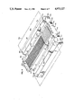
- FIG. 4 is an isometric view of a lower guide plate included in the right-hand plug of FIG. 3;
- FIG. 5 is a left side elevation of such right hand plug
- FIG. 6 is a right side elevation of such right hand plug
- FIG. 7 is a right side elevation of the left hand plug of FIG. 3;
- FIG. 8 is a left side elevation of such left hand plug
- FIG. 9 is a schematic cross-sectional fragmentary view of a manner of forming a mold insert used in fabricating the FIG. 4 guide plate and other guide plates;
- FIG. 10 is a schematic plan view of (a) a holding fixture used in the assembling of the plugs shown in FIG. 3, and (b) of the FIG. 4 guide plate received in that fixture;
- FIG. 11 is a schematic front elevation of the FIG. 10 fixture, and of both guide plates of the right hand plug received in that fixture;
- FIG. 12 is a schematic isometric view of a fixture used as an aid in polishing the front end faces of FIG. 3;
- FIG. 13 is an enlarged cross-sectional view, taken as indicated by the arrows (1-13 in FIG. 1, of a portion of the right hand plug of the FIG. 1 connector.
- the reference number 20 designates a multifiber optical connector comprising right and left hand plugs 25, 25' constituting respective terminations for separate optical fiber cables 26, 26'.
- Cable 26 comprises a synthetic resinous ribbon 27 in the body of which are embedded twelve laterally spaced optical fibers f (individually designated f1, f2 . . . f11, f12) of which some are shown in FIG. 1.
- Cable 26' comprises a similar ribbon 27' in which are embedded similar optical fibers f.
- the fibers f and f each comprise a core and cladding, and may be either single mode or multimode fibers. Lengths of the fibers pass forwardly through their corresponding plugs to terminate in fiber ends exposed at the front surfaces of the plugs.
- the two plugs are shown in FIGS. 1 and 2 as being coupled together by a pair of aligning pins 45, 45' each received partly in one plug and partly in the other to form the assembled connector 20.
- the pins 45, 45' are metal or ceramic pins dimensioned with great precision and having good dimensional stability. Those pins position the plugs relative to each other to produce an accurate alignment of the end of each fiber in plug 25 with the end of the corresponding fiber in plug 25'. The result is a low loss optical splice between the fibers f of cable 26 and their counterpart fibers f of cable 26'.
- the optical interconnection of the two sets of fibers may readily be interrupted by detaching plugs 25 and 25' from each other to become decoupled as shown in FIG. 3.
- the pins 45 and 45' are shown as remaining in the plugs 25 and 25', respectively. If desired, however, both of the pins may remain in the plug 25 or the plug 25', or both pins may be entirely separated from both plugs. Because the plugs 25 and 25' may selectively be coupled and decoupled, the described connector 20 is a make-break connector well adapted for field use.
- Plug 25 comprises lower and upper synthetic resinous guide plates 50a, 50b, plug 25' comprising similar guide plates 50a', 50b'.
- Plates 50b, 50a', 50b' are duplicates of guide plate 50a of which details are shown in FIG. 4. All such guide plates may be constituted, for example, of glass filled thermoset epoxy such as PLASKON 2929B sold by PLASKON Electronic Materials, a subsidiary of Rohm & Haas Company.
- plate 50a is a generally rectangular body having inner and outer parallel sides 51a, 52a vertically separated from each other in the transverse or thickness dimension of the plate.
- Inner side 51a has an upwardly presented face 53a extending longitudinally and laterally in a horizontal inner face plane 54a for such plate.
- Formed in a laterally central region of such inner side 51a is an array of twelve laterally spaced parallel fiber receptacle grooves 60a-71a extending transversely into the body of plate 50a from its face 53a. Those grooves are all parallel to the longitudinal axis 130 (FIG. 3) of the plate, and they all run from the plate's rear 72a to its front 73a.
- each groove has two laterally separated planar side walls defining two planes which meet at a line of intersection to define a dihedral angle bisected by the plane passing through that line and perpendicular to the face plane 54a.
- the mentioned sidewalls of each groove extend all the way down to a common intersection line to render such groove of full "V" configuration in lateral-transverse cross-section.
- those sidewalls of such V-sided grooves may, for each, terminate at a flat groove bottom short of such intersection so that the groove is of truncated "V" configuration in cross-section.
- V-defining sidewalls of such grooves need not reach all the way to the face 53a from which the grooves 60a-71a extend transversely into the plate.
- the grooves 60a-71a are divided into respective forward portions and respective rear portions lying in, respectively, a forward interval 76a and a rear interval 77a of the side 51a of the plate 50a. Over the length of the forward portion of each such groove, it is of uniform cross-section, and the same is true over the length of its rear portion. However, the rear portion of that groove is larger in cross-section than its forward portion. Between the mentioned intervals 76a and 77a is a zone 78a of short length in which the bounding walls of the grooves 60a-71a are tapered to provide faired transitions from their larger cross-section section rear portions to their smaller cross-section front portions. The enlarging of the rear parts of the grooves 60a-71a facilitates the inserting therein of the optical fibers f.
- the array of fiber grooves 60a-71a is flanked on its laterally opposite sides by a pair of pin receptacle grooves 80a, 81a formed in the inner face 53a of plate 50a and extending longitudinally in that plate from its rear 72a to its front 73a in parallel relation with grooves 60a-71a.
- the pin grooves in lateraltransverse cross-section have a cross-sectional area larger by at least one order of magnitude than that of the fiber grooves.
- the pin grooves 80a, 81a are V-sided grooves in the sense described above, they have flat bottoms so that they have a truncated "V" cross-sectional configuration rather than one which is a full "V".
- the pin grooves 80a, 81 have rear portions of slightly enlarged cross-sections relative to that of their front portions in interval 76a. In the case of the pin grooves, however, there is no tapered transition between their front and rear portions. Instead at the intersection of those portions, the bounding walls of the grooves 80a, 81a have formed therein rearward-facing shoulders 82a, 83a extending perpendicular to the axes of the grooves and adapted to act as stops.
- the plate 50a in its laterally central region has a pedestal 85a projecting forwardly from the surrounding area of the plates front end 73a and having slanted side walls 86a, 87a convergently tapering forwardly to a planar end face 88a for the pedestal.
- End face 88a is perpendicular to both the plate's inner face plane 54a and its transverse-longitudinal center plane 125a (FIGS. 6 and 7).
- the fiber grooves 60a-71a extend forwardly through pedestal 85a to openings thereof included within end face 88a.
- such end face projects forward of and is laterally inward of the forward terminations 89a, 90a of the pin grooves 80a, 81a.
- the outer side 52a of plate 50a has formed therein a pair of slots 93a, 94a extending longitudinally through the plate from its rear 72a to its front 73a.
- the slots 93a, 94a are disposed adjacent the laterally inward margins of the pin grooves 80a, 81a.
- the two slots extend transversely into the material of plate 50a to divide it into a central region 95a disposed laterally between the slots, and into two outer regions 96a, 97a outside the slots.
- the slots 93a, 94a reduce the transverse-longitudinal cross-section of the plate transversely inward of the slots so as to form necks 98a, 99a by which central region 95a is connected to the outboard regions 96a and 97a, respectively.
- FIGS. 5 and 6 the lower guide plate 50a is shown disposed in plug 25 in assembled relation with the upper guide plate 50b so that the two plates are in vertically juxtaposed relation with their respective inner faces 53a, 53b confronting each other and being separated by a transverse gap 100 between those faces.
- the two plates moreover are aligned in the lateral direction so that their respective fiber grooves 60a-71a and 60b-71b register with each other across gap 100 to define twelve fiber receptacle channels c (individually designated as c1, c2 . . . c11, c12) extending longitudinally through plug 25.
- Each such channel comprises (i) a fiber groove in the lower plate, (ii) the fiber groove in the upper plate directly above such lower fiber groove and (iii) the portion of the gap between such two grooves.
- fiber channel c1 the two grooves 60a and 71b which are components of that channel don't match in their reference numerals. That lack of match is due to the fact that plate 50b, although a duplicate of plate 50a has, from a starting position the same as plate 50a, been rotated 180° about a horizontal axes in the course of positioning plate 50b above plate 50a.
- pin grooves 80a, 81a, 80b, 81b of the two plates register with each other across gap 100 to define two pin channels 115 and 116 extending longitudinally through plug 25.
- Pin channel 115 comprises grooves 80a, 81b and the gap portion between them, while pin channel 116 comprises grooves 81a, 80b and their common gap portion.
- Channel 115 is shown as having received therein the aligning pin 45.
- the longitudinal axes 105, 106 of the pin channels 115, 116 are transversely disposed to be within gap 100.
- the optical fibers f1 . . . f12 associated with plug 25 are received in fiber channels c1 . . . c12, respectively, to extend therein forwardly to planar ends e (individually designated as e1, e2 . . . e11, e12) of such fibers at the front of the plug.
- e planar ends
- e subset of planar ends e
- portions of a body 135 FIG. 6
- the adhesive material of body 135 fills all the space in channels e not occupied by the fibers f to embed the fibers in that material.
- such material fills the lateral portions of gap 100 which lie between adjacent ones of these channels and, also, two short lateral portions of such gap which are outwards of the outside channels c1 and c12.
- the adhesive body 135 laterally terminates at edges 136, 137 for such body which are laterally inwards of the pin channels 115, 116.
- the lower and upper plates 50a, 50b are adhesively bonded together only between the edges 136 and 137. Laterally outwards of those edges, the plates remain separated by portions 138 of the gap 100 which are still air gaps.
- the pedestals 85a, 85b on guide plates 50a, 50b cooperate to form for the plug 25 a forwardly projecting nose 85 having a planar end face 88 normal to the longitudinal axis 130 of plug 25. Areas of face 88 are provided by the end faces 88a, 88b of the two pedestals, other areas are provided by the exposures (in the plane of that end face) of the adhesive material 135 in gap 100, and still other areas are provided by the exposures (in that plane) of the forward ends e of the optical fibers f.
- plug 25' duplicates that of the plug 25.
- Aligning pin 45' is received in the pin channel 115' of the plug 25'.
- the nose 85' of that plug has a planar end face 88' normal to the longitudinal axis 130' of plug 25'. Areas of that end face 88' are provided by (i) the end faces 88a', 88b' of the pedestals on the lower and upper guide plates in the plug, (ii) exposures in the plane of that end face of the material of adhesive body 135', and (iii) exposures in that plane of the ends e' of the optic fibers f received in plug 25'.
- the insert is subsequently placed in a mold in which the plates 50a, 50b, 50a', 50b' are produced by transfer molding, and in which a positive replica of the original silicon chip groove pattern appears on the inner side of each plate.
- the groove pattern can be reproduced in silicon with such accuracy that more than one master chip (each with the same groove pattern formed therein) can be used to provide different of the guide plates in the connector.
- those of its portions which do not correspond to the guide plate groove portions used for accurately positioning the fibers and aligning pins may be formed by machining rather than being derived from a silicon chip.
- the plug 25, for example, is assembled by the use of a crib fixture 160 (FIGS. 10 and 11) comprising a base 161 having upstanding therefrom vertical side walls 162, 163 and vertical front and rear walls 164, 165 with central openings 166, 167 therein.
- Walls 162-165 define on the upper surface of base 161 a rectangular enclosure within which guide plates 50a, 50b fit with small clearance in relation to such walls.
- guide plate 50a is placed on such surface in such enclosure with the plate's inner face 53a being upward. There is then passed through opening 167 into the pin grooves 80a, 81a, a pair of spacer pins 168, 168' of greater diameter than the aligning pins 45, 45' already described. On top of those pins is next added guide plate 50b (FIG. 11). The presence of the spacer pins between the plates 50a, 50b provides a preliminary alignment in the lateral direction between the grooves in the two plates.
- pins 168, 168' in contrast to pins 45, 45', serves to increase the size of the transverse gap between them to thereby make easier the insertion of the optical fibers f between the plates.
- the optical fibers f are inserted into the fiber receptacle channels c and are pushed forward therein until the fiber ends e project slightly beyond the forward terminations of those channels.
- the spacer pins 168, 168' are then removed, one at a time, from between the plates 50a, 50b. When this is done, plate 50b settles down on the fibers f to be supported above plate 50a by those fibers.
- Above guide plate 50b is positioned a horizontal pressure plate 170 fixed to a vertically movable plunger 171 and held thereby so that the lower surface of plate 170 is and remains parallel to the upper surface of base 160 during plunger operation.
- the downward force exertable by plunger 171 is controllable in magnitude.
- the plunger 171 is actuated to advance plate 170 in contact with the top of guide plate 50b and then urge it down to press together, with a moderate selected amount of force, the guide plates 50a, 50b and the fibers f therebetween. While the plate assembly is under such force, the material of adhesive body 135 is introduced into the fiber channels c and into gap 100.
- FIG. 12 shows a polishing fixture 179 comprising a hollow cylinder 180 with an open top 181 and an annular bottom 182 extending around a circular aperture (not shown) having a diameter greater than the width of ribbon 27 of cable 26 and less than the spacing between the pin channels 115, 116 (FIG. 5).
- a slot 183 passes radially through the wall of cylinder 180 and extends radially through the bottom 182 therefor from the outside of fixture 179 to the mentioned aperture.
- a pair of fixture positioning pins 184, 185 on opposite sides of such aperture.
- Cylinder 180 terminates at its top 181 in a split annular planar end face 186 providing a reference surface.
- Fixture 179 is used as follows with the assembled plug 25 and attached ribbon cable 26.
- Plug 25 is initially positioned out beyond the top of the fixture with cable 26 running past the fixture in alignment with and outside slot 183. The cable is then inserted through the slot into the interior of cylinder 180 so that the cable axially passes through the aperture in bottom 182.
- Plug 25 is then moved into the interior of fixture 179 so as to advance the fixture's pins 184, 185 into the enlarged rear portions of the pin channels 115, 116 of the plug. Such advance continues until stopped by engagement of the fronts of such pins with the shoulders 82, 83 (FIG. 4) in these channels. Fixture 179 thereby becomes fixed in position relative to plug 25.
- Plug 25' is made, assembled and polished in like manner to that set out above.
- the two completed plugs are then coupled and aligned by aligning pins 45, 45' to form connector 20, all as earlier described.
- Either of such pins may be either removably inserted into the pin channel of the plug by which that pin is carried or, alternatively, may be permanently anchored in that channel by adhesive.
- the term "nominal” refers to that positioning, size or other dimensional feature of something which it would actually have if there were no deviation whatever of such positioning, size or other dimensional feature from a numerically specified value therefor.
- the groove patterns in the upper and lower guide plates 50b and 50a are duplicates by virtue of being derived from the same groove pattern in the single master silicon chip 150 (FIG. 9) or from being derived from identical groove patterns formed in a plurality of such master silicon chips.
- the second feature is that the fiber grooves and pin grooves in each of plates 50b and 50a are bilaterally symmetrical in their positioning and dimensioning about the transverse-longitudinal center planes 125b, 125a of such plates.
- the pin grooves of such upper and lower plates also be characterized by such two features. That is so for the following reasons. It is the fact that, upon removal of the spacer pins 168, 168' from between plates 50a, 50b and subsequent application from pressure plate 170 of pressure to those two guide plates (FIG. 11), the lateral alignment ultimately assumed by the upper and lower pin grooves will be determined by the optical fibers f squeezed between these guide plates.
- the pin grooves should be characterized (to at least an extent) by the mentioned two features in order to prevent the insertion of the spacer pins into the pin channels formed by those pin grooves from laterally misaligning the upper and lower fiber grooves so far that such misalignment would, say, prevent the feeding of the optical fibers into the channels defined between the upper and lower fiber grooves.
- the pin grooves if their actual positioning in the upper and lower guide plates were to depart too much from a bilateral symmetrical positioning thereof, then after plates 50a and 50b were bonded together by adhesive as earlier described (FIGS. 10 and 11), the upper and lower pin grooves might be so laterally misaligned as to fail to define appropriate pin channels between them for insertion of the aligning pins 45, 45'.
- Plugs 25 and 25' have differentiated front and rear portions thereof in that their fronts have noses thereon while the rear portions have none, the grooves in such portions are enlarged in size at the rear of the plugs as compared to their front size, and so on.
- the groove patterns in the upper and lower guide plates need not be bilaterally symmetrical.
- the groove patterns in the two plates will still match to permit proper lateral and transverse alignment of the grooves therein. Even in that case, however, the groove patterns in the two plates should be duplicates, and it is still necessary to rotate, as described, the upper plate 180° about its longitudinal axis.
- plane 200 is the center plane of gap 100 and is disposed parallel to and midway between the respective face planes 54a, 54b of plates 50a, 50b.
- the relative cross-sectional sizes of the pin grooves and optical fibers should be chosen so that as taught in U.S. Pat. No. 3,864,018, application of such force does not reduce to zero the size of gap 100.
- That the axes a of all such fibers can so be made to be in center plane 200 is attributable to various factors such as the duplicate character of the upper and lower fiber grooves of each fiber channel in the plates 50a, 50b, the geometry favorable to that result of squeezing the fibers between pairs of V grooves on opposite sides of the fibers, and the fact that the synthetic resinous material of the plates 50a, 50b is resiliently deformable to yield to accommodate oversize fibers in the fiber channels.
- Center plane 200 includes not only the axes of the optical fibers 30-41 but also the axes 205, 205' of the aligning pins 45, 45' when received in the plugs 25 and 25'.
- the inclusion of such axes in that plane reduces or removes the possibility of transverse misalignment of the plugs 25 and 25' even when plug 25' is positioned "upside down" relative to plug 25.
- the positioning of the alignment pin axes in plane 200 cancels out the transverse misaligning effect of transverse deviations from nominal in the size of the pins and other dimensional features of plug 25. Note however that for such pin axes to be in plane 200, more of the diameter of the pins is required to be in the pin grooves than the fraction of the diameter of the fibers in the fiber grooves.
- Plug 25' will of course have the same features as those of plug 25 described above. The incorporation of such features in both plugs results not only for each, in the good “intra-plug” lateral and transverse alignment which have been considered but also in good “extra-plug” lateral, transverse and angular alignments between the two plugs when coupled together.
- the aligning pins 45, 45' are oversize in the sense that they are of such diameter in relation to the cross-sectional size of their pin channels 115, 116 in plug 25 and 115', 116' in plug 25' that the pins cannot be frictionlessly slid into such channels. Instead the pins must be forced into such channels and are received therein with a playless fit. This could be done even if such channels were in the form of circular holes continuously surrounded around their peripheries by the material of the plug in which formed. The cost, however, of such would be that, with a deviation type increase in the diameter of the pin, the force needed advance the pin into the channel would rise very rapidly.
- pin channels defined by grooves formed in sections 96, 97 of the plugs which are laterally outward of the adhesive body 135 and are thus free to resiliently deform towards or away from each other to vary the transverse size of the pin channel.
- An example of such a pin channel is the channel 115 (FIG. 3) defined between the grooves 80a, 81b in, respectively, the outboard portions 96a, 97b of the guide plates 50a, 50b of plug 25.
- aligning pin 45 can readily be made sufficiently oversize to absorb, say, variations in the size of gap 100 (caused by deviation from nominal in the optical fibers f in the plug) or thermal variations in the diameter of the pin itself without becoming loose in the pin channel.
- resiliently deformable plate portions 96, 97 Another advantage of the resiliently deformable plate portions 96, 97 is that, when they are resiliently deformed towards or away from each other as a result of variations in the diameter of the aligning pin inserted into or removed from the channel 115, the two portions will deflect symmetrically relative to the center plane 200. In consequence, the axis 205 of pin 45 will remain in such plane unaffected by such resilient deformation responsive to such variations. Similarly the axes 105, 106 of pin channels 115 and 116 (FIG. 5) will be in and stay in plane 200 at all times despite any such variations.
- end faces 88, 88' are smaller in area than the whole cross-sectional size, at their front ends, of plugs 25 and 25'.
- end faces 88, 88' are easier to polish and to render normal to the plug axes 130, 130' than would be the case for a front surface extending over the whole of such front ends.
- FIG. 1 Another benefit derived from having such noses 85, 85' is that when plugs 25, 25' are coupled together (FIG. 1), portions 210, 210' of the aligning pins are left exposed between the plugs 25, 25' to not be received in the pin channels of such plugs.
- portions 210, 210' of the aligning pins are left exposed between the plugs 25, 25' to not be received in the pin channels of such plugs.
- For the pins to have such exposed portions is advantageous because, if necessary, they are free to deflect over the lengths of such portions to accommodate any difference in the respective lateral spacings in plugs 25 and 25' of the pin channels therein.
- each such exposed portion may be made either incrementally shorter or incrementally longer in the event it is found desirable to incrementally change the angular position of one of plugs 25, 25' relative to the other.
- the connector 20 described above is adapted to splice optical fibers with a mean loss of less than 0.3 dB and a stability within 0.1 dB between -40° C. to 85° C.
Abstract
Description
Claims (28)
Priority Applications (1)
| Application Number | Priority Date | Filing Date | Title |
|---|---|---|---|
| US07/359,453 US4973127A (en) | 1989-05-31 | 1989-05-31 | Multifiber optical connector and method of making same |
Applications Claiming Priority (1)
| Application Number | Priority Date | Filing Date | Title |
|---|---|---|---|
| US07/359,453 US4973127A (en) | 1989-05-31 | 1989-05-31 | Multifiber optical connector and method of making same |
Publications (1)
| Publication Number | Publication Date |
|---|---|
| US4973127A true US4973127A (en) | 1990-11-27 |
Family
ID=23413854
Family Applications (1)
| Application Number | Title | Priority Date | Filing Date |
|---|---|---|---|
| US07/359,453 Expired - Lifetime US4973127A (en) | 1989-05-31 | 1989-05-31 | Multifiber optical connector and method of making same |
Country Status (1)
| Country | Link |
|---|---|
| US (1) | US4973127A (en) |
Cited By (64)
| Publication number | Priority date | Publication date | Assignee | Title |
|---|---|---|---|---|
| US5016972A (en) * | 1987-08-20 | 1991-05-21 | Siemens Aktiengesellschaft | Detachable multiple splicing connector for light waveguides |
| US5037179A (en) * | 1989-07-24 | 1991-08-06 | Societa' Cavi Pirelli S.P.A. | Interconnect system for coupling ribbon optical fibers and method of making the same |
| US5044711A (en) * | 1989-10-17 | 1991-09-03 | Sumitomo Electric Industries, Ltd. | Optical-fiber aligning member and method of forming the member |
| US5080461A (en) * | 1990-10-31 | 1992-01-14 | At&T Bell Laboratories | Retracting optical fiber connector |
| US5082346A (en) * | 1990-06-28 | 1992-01-21 | At&T Bell Laboratories | Field-assemblable multifiber optical connector |
| US5091988A (en) * | 1991-04-12 | 1992-02-25 | At&T Bell Laboratories | Article for connecting optical fibers |
| EP0564207A2 (en) * | 1992-03-30 | 1993-10-06 | Ngk Insulators, Ltd. | Optical fiber connector |
| US5337384A (en) * | 1993-07-06 | 1994-08-09 | At&T Bell Laboratories | Optical fiber connector |
| EP0613031A1 (en) * | 1993-02-22 | 1994-08-31 | AT&T Corp. | Methods for making optical fiber connectors |
| US5361317A (en) * | 1993-06-14 | 1994-11-01 | Motorola, Inc. | Assembly with fixture aligning and affixing an optical fiber to an optical device |
| EP0624808A1 (en) * | 1993-03-29 | 1994-11-17 | Sumitomo Electric Industries, Ltd. | Optical connector |
| US5379361A (en) * | 1992-03-30 | 1995-01-03 | Ngk Insulators, Ltd. | Optical fiber connector including L-shaped positioning standard surfaces and method of manufacturing the same |
| US5420954A (en) * | 1993-05-24 | 1995-05-30 | Photonics Research Incorporated | Parallel optical interconnect |
| US5425118A (en) * | 1992-12-28 | 1995-06-13 | Matsushita Electric Industrial Co., Ltd. | Optical component mounting substrate and method of producing the same |
| EP0665455A1 (en) * | 1994-01-27 | 1995-08-02 | AT&T Corp. | Optical fiber connector techniques |
| US5685945A (en) * | 1995-12-29 | 1997-11-11 | Lucent Technologies Inc. | Method and apparatus for separating one or more optical fibers from an optical fiber ribbon |
| EP0826996A1 (en) * | 1996-07-31 | 1998-03-04 | Kyocera Corporation | Optical element retaining member and method of manufacturing same |
| US5737463A (en) * | 1995-12-22 | 1998-04-07 | Weiss; Roger E. | Massive parallel optical interconnect system |
| US5748818A (en) * | 1995-12-22 | 1998-05-05 | Weiss; Roger E. | Massive parallel optical interconnect system |
| US5838856A (en) * | 1995-10-31 | 1998-11-17 | Daewoo Telecom, Ltd. | Optical-fiber cable connector assembly |
| US5944949A (en) * | 1997-11-12 | 1999-08-31 | Lucent Technologies Inc. | Method and apparatus for separating one or more optical fibers from an optical fiber ribbon |
| US6045270A (en) * | 1995-12-22 | 2000-04-04 | Methode Electronics, Inc. | Massive parallel optical interconnect system |
| EP1033595A1 (en) * | 1999-03-04 | 2000-09-06 | Lucent Technologies Inc. | Stackable multi-fiber ferrules having improved interconnection density |
| EP1033594A1 (en) * | 1999-03-04 | 2000-09-06 | Lucent Technologies Inc. | Stackable multi-fiber ferrule assembly methods and tools |
| EP1039322A1 (en) * | 1999-03-25 | 2000-09-27 | Lucent Technologies Inc. | Small form factor multi-fiber optical connectors and methods for making same |
| EP1039324A1 (en) * | 1999-03-23 | 2000-09-27 | W.L. GORE & ASSOCIATES GmbH | Conductor guiding device for connector plug |
| US6234681B1 (en) | 1999-05-21 | 2001-05-22 | Lucent Technologies Inc. | Apparatus and method for interconnecting optical fibers |
| US6266472B1 (en) | 1999-09-03 | 2001-07-24 | Corning Incorporated | Polymer gripping elements for optical fiber splicing |
| US6298192B1 (en) * | 1999-01-12 | 2001-10-02 | Samsung Electronics Co., Ltd. | Optical waveguide device and method for fabricating the same |
| US20010041026A1 (en) * | 2000-04-13 | 2001-11-15 | Steinberg Dan A. | Optical waveguide switch |
| US20010048785A1 (en) * | 2000-04-14 | 2001-12-06 | Steinberg Dan A. | Fiber optic array switch |
| US20020025107A1 (en) * | 2000-08-28 | 2002-02-28 | Noel Heiks | Optical switch assembly and method for making |
| US6352372B1 (en) | 1999-10-11 | 2002-03-05 | Lucent Technologies Inc. | High-density optical connectors |
| US20020028037A1 (en) * | 2000-05-19 | 2002-03-07 | Steinberg Dan A. | Optical waveguide devices and methods of fabricating the same |
| US20020051618A1 (en) * | 2000-09-21 | 2002-05-02 | Ten Eyck Gregory A. | Fiber array with support post |
| US6447171B1 (en) * | 2000-02-04 | 2002-09-10 | Fci Americas Technology, Inc | Multi-fiber array connector system |
| US20020146194A1 (en) * | 2000-08-24 | 2002-10-10 | Sherrer David W. | Optical switch and method for making |
| US6474877B1 (en) | 2001-04-12 | 2002-11-05 | Fitel Usa Corporation | Alignment assembly for multi-optical fiber ferrules |
| US20030108272A1 (en) * | 2000-12-20 | 2003-06-12 | Sherrer David W. | Optical switch assembly with flex plate and method for making |
| WO2003065091A2 (en) * | 2002-01-29 | 2003-08-07 | Qinetiq Limited | Optical circuit including hollow core optical waveguides |
| US6628865B2 (en) | 2000-12-15 | 2003-09-30 | Intel Corporation | Alignment of optical fibers to an etched array waveguide |
| US6695488B2 (en) | 2001-07-19 | 2004-02-24 | Cinch Connectors, Inc. | Tool and method for forming a multi fiber ferrule |
| US6707970B2 (en) | 2000-12-15 | 2004-03-16 | Intel Corporation | Alignment of fiber optic bundle to array waveguide using an epoxy |
| US20040086255A1 (en) * | 2002-10-31 | 2004-05-06 | Botet Alfred D. | Stacked optical fiber arrays |
| US6799902B2 (en) | 2000-12-26 | 2004-10-05 | Emcore Corporation | Optoelectronic mounting structure |
| US6832016B2 (en) | 2000-04-13 | 2004-12-14 | Shipley Company, L.L.C. | Fiber array switch having micromachined front face with roller balls |
| US6842552B1 (en) | 2000-04-13 | 2005-01-11 | Shipley Company, L.L.C. | Optical waveguide switch |
| US6863444B2 (en) | 2000-12-26 | 2005-03-08 | Emcore Corporation | Housing and mounting structure |
| US6863453B2 (en) | 2003-01-28 | 2005-03-08 | Emcore Corporation | Method and apparatus for parallel optical transceiver module assembly |
| US6867377B2 (en) | 2000-12-26 | 2005-03-15 | Emcore Corporation | Apparatus and method of using flexible printed circuit board in optical transceiver device |
| US6886989B2 (en) * | 2000-12-15 | 2005-05-03 | Intel Corporation | Alignment of fiber optic bundle to array waveguide using pins |
| US6905260B2 (en) | 2000-12-26 | 2005-06-14 | Emcore Corporation | Method and apparatus for coupling optical elements to optoelectronic devices for manufacturing optical transceiver modules |
| US7021836B2 (en) | 2000-12-26 | 2006-04-04 | Emcore Corporation | Attenuator and conditioner |
| US7410304B2 (en) | 2001-11-08 | 2008-08-12 | Rohm And Haas Electronic Materials Llc | Optical fiber right angle transition |
| USRE43542E1 (en) | 2000-06-12 | 2012-07-24 | Adc Gmbh | Assembly and method for use in terminating an optical fiber or fibers |
| WO2012148879A1 (en) * | 2011-04-28 | 2012-11-01 | Corning Cable Systems Llc | Fiber assembly with tray feature |
| WO2013151583A1 (en) * | 2012-04-05 | 2013-10-10 | Nanoprecision Products, Inc. | Ferrule for optical fiber connector having a compliant structure for clamping alignment pins |
| US20140321809A1 (en) * | 2013-04-26 | 2014-10-30 | Tyco Electronics Corporation | Optical fiber subassembly |
| US20160154150A1 (en) * | 2012-12-10 | 2016-06-02 | Bae Systems Plc | Display comprising an optical waveguide and switchable diffraction gratings and method of producing the same |
| US20160259130A1 (en) * | 2015-03-02 | 2016-09-08 | Sumix | Methodology and design of fixtures for precision alignment of mtp/mpo connectors and mt ferrules in interferometric end-face measurements |
| JP2018072514A (en) * | 2016-10-27 | 2018-05-10 | 住友電気工業株式会社 | Optical component, optical device, and method of making optical device |
| US10663665B2 (en) * | 2017-11-30 | 2020-05-26 | Corning Research & Development Corporation | Ribbon handling device for fusion splicer and methods of fusion splicing |
| US11275211B2 (en) * | 2019-06-18 | 2022-03-15 | Cisco Technology, Inc. | Fiber array unit with unfinished endface |
| US11402582B2 (en) * | 2016-04-12 | 2022-08-02 | Nitto Denko Corporation | Optical connector member, optical connector kit, and optical interconnection |
Citations (10)
| Publication number | Priority date | Publication date | Assignee | Title |
|---|---|---|---|---|
| US3864018A (en) * | 1973-10-18 | 1975-02-04 | Bell Telephone Labor Inc | Method and means for splicing arrays of optical fibers |
| US4029390A (en) * | 1974-12-23 | 1977-06-14 | Bell Telephone Laboratories, Incorporated | Optical fiber group splicing technique and apparatus employing unique foldable holder |
| US4279468A (en) * | 1977-05-02 | 1981-07-21 | Plessey Handel Und Investments Ag | Optical fiber connectors |
| JPS57205704A (en) * | 1981-06-15 | 1982-12-16 | Nippon Telegr & Teleph Corp <Ntt> | Production of die for molding multicored connector for optical fiber |
| US4657341A (en) * | 1983-08-03 | 1987-04-14 | Siemens Aktiengesellschaft | Connector for light waveguides and method of producing same |
| US4818058A (en) * | 1988-03-03 | 1989-04-04 | American Telephone And Telegraph Company At&T Bell Laboratories | Optical connector |
| US4830456A (en) * | 1986-11-15 | 1989-05-16 | Sumitomo Electric Industries, Ltd. | Optical connector and process for producing the same |
| US4836638A (en) * | 1986-10-16 | 1989-06-06 | Siemens Aktiengesellschaft | Connector element for light waveguides |
| US4865413A (en) * | 1986-02-25 | 1989-09-12 | U.S. Philips Corp. | Arrangement for splicing optical waveguides and method of manufacturing same |
| US4898449A (en) * | 1987-08-04 | 1990-02-06 | U.S. Philips Corp. | Connector for the detachable connection of light conducting fibres |
-
1989
- 1989-05-31 US US07/359,453 patent/US4973127A/en not_active Expired - Lifetime
Patent Citations (11)
| Publication number | Priority date | Publication date | Assignee | Title |
|---|---|---|---|---|
| US3864018A (en) * | 1973-10-18 | 1975-02-04 | Bell Telephone Labor Inc | Method and means for splicing arrays of optical fibers |
| US4029390A (en) * | 1974-12-23 | 1977-06-14 | Bell Telephone Laboratories, Incorporated | Optical fiber group splicing technique and apparatus employing unique foldable holder |
| US4279468A (en) * | 1977-05-02 | 1981-07-21 | Plessey Handel Und Investments Ag | Optical fiber connectors |
| JPS57205704A (en) * | 1981-06-15 | 1982-12-16 | Nippon Telegr & Teleph Corp <Ntt> | Production of die for molding multicored connector for optical fiber |
| US4657341A (en) * | 1983-08-03 | 1987-04-14 | Siemens Aktiengesellschaft | Connector for light waveguides and method of producing same |
| US4865413A (en) * | 1986-02-25 | 1989-09-12 | U.S. Philips Corp. | Arrangement for splicing optical waveguides and method of manufacturing same |
| US4836638A (en) * | 1986-10-16 | 1989-06-06 | Siemens Aktiengesellschaft | Connector element for light waveguides |
| US4830456A (en) * | 1986-11-15 | 1989-05-16 | Sumitomo Electric Industries, Ltd. | Optical connector and process for producing the same |
| US4898449A (en) * | 1987-08-04 | 1990-02-06 | U.S. Philips Corp. | Connector for the detachable connection of light conducting fibres |
| US4818058A (en) * | 1988-03-03 | 1989-04-04 | American Telephone And Telegraph Company At&T Bell Laboratories | Optical connector |
| US4818058B1 (en) * | 1988-03-03 | 1995-04-25 | Bell Telephone Labor Inc | Optical connector. |
Non-Patent Citations (8)
| Title |
|---|
| C. M. Schroeder, "Accurate Silicone Space Chips for an Optical Fiber Cable Connector", Bell System Technical Journal, vol. 52, No. 1, Jan. 1978, pp. 91-97. |
| C. M. Schroeder, Accurate Silicone Space Chips for an Optical Fiber Cable Connector , Bell System Technical Journal, vol. 52, No. 1, Jan. 1978, pp. 91 97. * |
| Kurokama, et al., "Precisely Moulded Plastic Splices for Optical Fibres", Electronics Letters, Nov. 20, 1980, pp. 911-912. |
| Kurokama, et al., Precisely Moulded Plastic Splices for Optical Fibres , Electronics Letters, Nov. 20, 1980, pp. 911 912. * |
| Satake, et al., "Low Loss Multifibre Connectors with Plug-Guide Grooved Silicon", Electronics Letters, Nov. 29, 1981, pp. 828-830. |
| Satake, et al., "Low-Loss Plastic Molded Optical Multifiber Connector for Ribbon-to-Single Fiber Fan Out", Journal of Lightwave Technology, vol. LT-3, No. 6, Dec. 1985. |
| Satake, et al., Low Loss Multifibre Connectors with Plug Guide Grooved Silicon , Electronics Letters, Nov. 29, 1981, pp. 828 830. * |
| Satake, et al., Low Loss Plastic Molded Optical Multifiber Connector for Ribbon to Single Fiber Fan Out , Journal of Lightwave Technology, vol. LT 3, No. 6, Dec. 1985. * |
Cited By (105)
| Publication number | Priority date | Publication date | Assignee | Title |
|---|---|---|---|---|
| US5016972A (en) * | 1987-08-20 | 1991-05-21 | Siemens Aktiengesellschaft | Detachable multiple splicing connector for light waveguides |
| AU640147B2 (en) * | 1989-07-24 | 1993-08-19 | Prysmian Cavi E Sistemi Energia S.R.L. | Detachable connecting group for ribbon optical fibers and method of making the same |
| US5037179A (en) * | 1989-07-24 | 1991-08-06 | Societa' Cavi Pirelli S.P.A. | Interconnect system for coupling ribbon optical fibers and method of making the same |
| US5044711A (en) * | 1989-10-17 | 1991-09-03 | Sumitomo Electric Industries, Ltd. | Optical-fiber aligning member and method of forming the member |
| US5082346A (en) * | 1990-06-28 | 1992-01-21 | At&T Bell Laboratories | Field-assemblable multifiber optical connector |
| US5080461A (en) * | 1990-10-31 | 1992-01-14 | At&T Bell Laboratories | Retracting optical fiber connector |
| US5091988A (en) * | 1991-04-12 | 1992-02-25 | At&T Bell Laboratories | Article for connecting optical fibers |
| EP0564207A2 (en) * | 1992-03-30 | 1993-10-06 | Ngk Insulators, Ltd. | Optical fiber connector |
| EP0564207A3 (en) * | 1992-03-30 | 1994-04-20 | Ngk Insulators Ltd | |
| US5315678A (en) * | 1992-03-30 | 1994-05-24 | Nippon Telegraph & Telephone Corporation | Optical fiber connector |
| US5379361A (en) * | 1992-03-30 | 1995-01-03 | Ngk Insulators, Ltd. | Optical fiber connector including L-shaped positioning standard surfaces and method of manufacturing the same |
| US5425118A (en) * | 1992-12-28 | 1995-06-13 | Matsushita Electric Industrial Co., Ltd. | Optical component mounting substrate and method of producing the same |
| EP0613031A1 (en) * | 1993-02-22 | 1994-08-31 | AT&T Corp. | Methods for making optical fiber connectors |
| US5420952A (en) * | 1993-03-29 | 1995-05-30 | Sumitomo Electric Industries, Ltd. | Optical connector employing two different types of adhesives |
| EP0624808A1 (en) * | 1993-03-29 | 1994-11-17 | Sumitomo Electric Industries, Ltd. | Optical connector |
| US5420954A (en) * | 1993-05-24 | 1995-05-30 | Photonics Research Incorporated | Parallel optical interconnect |
| US5631988A (en) * | 1993-05-24 | 1997-05-20 | Vixel Corporation | Parallel optical interconnect |
| US5361317A (en) * | 1993-06-14 | 1994-11-01 | Motorola, Inc. | Assembly with fixture aligning and affixing an optical fiber to an optical device |
| US5337384A (en) * | 1993-07-06 | 1994-08-09 | At&T Bell Laboratories | Optical fiber connector |
| EP0665455A1 (en) * | 1994-01-27 | 1995-08-02 | AT&T Corp. | Optical fiber connector techniques |
| US5838856A (en) * | 1995-10-31 | 1998-11-17 | Daewoo Telecom, Ltd. | Optical-fiber cable connector assembly |
| US5737463A (en) * | 1995-12-22 | 1998-04-07 | Weiss; Roger E. | Massive parallel optical interconnect system |
| US5748818A (en) * | 1995-12-22 | 1998-05-05 | Weiss; Roger E. | Massive parallel optical interconnect system |
| US6045270A (en) * | 1995-12-22 | 2000-04-04 | Methode Electronics, Inc. | Massive parallel optical interconnect system |
| US6276840B1 (en) | 1995-12-22 | 2001-08-21 | Stratos Lightwave, Inc. | Massive parallel optical interconnect system |
| US5685945A (en) * | 1995-12-29 | 1997-11-11 | Lucent Technologies Inc. | Method and apparatus for separating one or more optical fibers from an optical fiber ribbon |
| EP0826996A1 (en) * | 1996-07-31 | 1998-03-04 | Kyocera Corporation | Optical element retaining member and method of manufacturing same |
| US5944949A (en) * | 1997-11-12 | 1999-08-31 | Lucent Technologies Inc. | Method and apparatus for separating one or more optical fibers from an optical fiber ribbon |
| EP1064577A1 (en) * | 1998-03-19 | 2001-01-03 | Stratos Lightwave, Inc. | Massive parallel optical interconnect system |
| EP1064577A4 (en) * | 1998-03-19 | 2006-04-26 | Stratos Int Inc | Massive parallel optical interconnect system |
| US6298192B1 (en) * | 1999-01-12 | 2001-10-02 | Samsung Electronics Co., Ltd. | Optical waveguide device and method for fabricating the same |
| US6256448B1 (en) | 1999-03-04 | 2001-07-03 | Lucent Technologies Inc. | Stackable multi-fiber ferrule assembly methods and tools |
| EP1033594A1 (en) * | 1999-03-04 | 2000-09-06 | Lucent Technologies Inc. | Stackable multi-fiber ferrule assembly methods and tools |
| US6259856B1 (en) | 1999-03-04 | 2001-07-10 | Lucent Technologies, Inc. | Small form factor multi-fiber optical connectors and methods for making same |
| US6364539B1 (en) | 1999-03-04 | 2002-04-02 | Avaya Technology Corp. | Stackable multi-fiber ferrules having improved interconnection density |
| EP1033595A1 (en) * | 1999-03-04 | 2000-09-06 | Lucent Technologies Inc. | Stackable multi-fiber ferrules having improved interconnection density |
| EP1039324A1 (en) * | 1999-03-23 | 2000-09-27 | W.L. GORE & ASSOCIATES GmbH | Conductor guiding device for connector plug |
| EP1039322A1 (en) * | 1999-03-25 | 2000-09-27 | Lucent Technologies Inc. | Small form factor multi-fiber optical connectors and methods for making same |
| US6234681B1 (en) | 1999-05-21 | 2001-05-22 | Lucent Technologies Inc. | Apparatus and method for interconnecting optical fibers |
| US6266472B1 (en) | 1999-09-03 | 2001-07-24 | Corning Incorporated | Polymer gripping elements for optical fiber splicing |
| US6352372B1 (en) | 1999-10-11 | 2002-03-05 | Lucent Technologies Inc. | High-density optical connectors |
| US6447171B1 (en) * | 2000-02-04 | 2002-09-10 | Fci Americas Technology, Inc | Multi-fiber array connector system |
| US20010041026A1 (en) * | 2000-04-13 | 2001-11-15 | Steinberg Dan A. | Optical waveguide switch |
| US6842552B1 (en) | 2000-04-13 | 2005-01-11 | Shipley Company, L.L.C. | Optical waveguide switch |
| US6832016B2 (en) | 2000-04-13 | 2004-12-14 | Shipley Company, L.L.C. | Fiber array switch having micromachined front face with roller balls |
| US6826324B2 (en) | 2000-04-13 | 2004-11-30 | Shipley Company, L.L.C. | Optical waveguide switch |
| US20010048785A1 (en) * | 2000-04-14 | 2001-12-06 | Steinberg Dan A. | Fiber optic array switch |
| US6798933B2 (en) | 2000-04-14 | 2004-09-28 | Shipley Company, L.L.C. | Fiber optic array switch |
| US6973253B2 (en) | 2000-05-19 | 2005-12-06 | Shipley Company, L.L.C. | Optical waveguide devices and methods of fabricating the same |
| US6748131B2 (en) | 2000-05-19 | 2004-06-08 | Shipley Company, L.L.C. | Optical waveguide devices and methods of fabricating the same |
| US20040208469A1 (en) * | 2000-05-19 | 2004-10-21 | Steinberg Dan A. | Optical waveguide devices and methods of fabricating the same |
| US20060275012A1 (en) * | 2000-05-19 | 2006-12-07 | Shipley Company, L.L.C. | Optical waveguide devices and methods of fabricating the same |
| US7065283B2 (en) | 2000-05-19 | 2006-06-20 | Shipley Company, L.L.C. | Optical waveguide devices and methods of fabricating the same |
| US20040228600A1 (en) * | 2000-05-19 | 2004-11-18 | Steinberg Dan A. | Optical waveguide devices and methods of fabricating the same |
| US20020028037A1 (en) * | 2000-05-19 | 2002-03-07 | Steinberg Dan A. | Optical waveguide devices and methods of fabricating the same |
| USRE43542E1 (en) | 2000-06-12 | 2012-07-24 | Adc Gmbh | Assembly and method for use in terminating an optical fiber or fibers |
| US6870981B2 (en) | 2000-08-24 | 2005-03-22 | Shipley Company, L.L.C. | Optical switch and method for making |
| US20020146194A1 (en) * | 2000-08-24 | 2002-10-10 | Sherrer David W. | Optical switch and method for making |
| US20020025107A1 (en) * | 2000-08-28 | 2002-02-28 | Noel Heiks | Optical switch assembly and method for making |
| US6853764B2 (en) * | 2000-08-28 | 2005-02-08 | Shipley Company, L.L.C. | Optical switch assembly and method for making |
| US6798968B2 (en) | 2000-09-21 | 2004-09-28 | Shipley Company, L.L.C. | Fiber array with support post |
| US20020051618A1 (en) * | 2000-09-21 | 2002-05-02 | Ten Eyck Gregory A. | Fiber array with support post |
| US20050180716A1 (en) * | 2000-12-15 | 2005-08-18 | Crafts Douglas E. | Alignment of fiber optic bundle to array waveguide using pins |
| US6707970B2 (en) | 2000-12-15 | 2004-03-16 | Intel Corporation | Alignment of fiber optic bundle to array waveguide using an epoxy |
| US6886989B2 (en) * | 2000-12-15 | 2005-05-03 | Intel Corporation | Alignment of fiber optic bundle to array waveguide using pins |
| US6628865B2 (en) | 2000-12-15 | 2003-09-30 | Intel Corporation | Alignment of optical fibers to an etched array waveguide |
| US20050074201A1 (en) * | 2000-12-20 | 2005-04-07 | Sherrer David W. | Optical switch assembly with flex plate and method for making |
| US6810162B2 (en) | 2000-12-20 | 2004-10-26 | Shipley Company, L.L.C. | Optical switch assembly with flex plate and method for making |
| US7079725B2 (en) | 2000-12-20 | 2006-07-18 | Shipley Company, L.L.C. | Optical switch assembly with flex plate and method for making |
| US20030108272A1 (en) * | 2000-12-20 | 2003-06-12 | Sherrer David W. | Optical switch assembly with flex plate and method for making |
| US6905260B2 (en) | 2000-12-26 | 2005-06-14 | Emcore Corporation | Method and apparatus for coupling optical elements to optoelectronic devices for manufacturing optical transceiver modules |
| US6867377B2 (en) | 2000-12-26 | 2005-03-15 | Emcore Corporation | Apparatus and method of using flexible printed circuit board in optical transceiver device |
| US6863444B2 (en) | 2000-12-26 | 2005-03-08 | Emcore Corporation | Housing and mounting structure |
| US7021836B2 (en) | 2000-12-26 | 2006-04-04 | Emcore Corporation | Attenuator and conditioner |
| US6799902B2 (en) | 2000-12-26 | 2004-10-05 | Emcore Corporation | Optoelectronic mounting structure |
| US6474877B1 (en) | 2001-04-12 | 2002-11-05 | Fitel Usa Corporation | Alignment assembly for multi-optical fiber ferrules |
| US20040170361A1 (en) * | 2001-07-19 | 2004-09-02 | Cinch Connectors, Inc. | Tool and method for forming a multifiber ferrule |
| US6848870B2 (en) | 2001-07-19 | 2005-02-01 | Cinch Connectors, Inc. | Tool and method for forming a multifiber ferrule |
| US6695488B2 (en) | 2001-07-19 | 2004-02-24 | Cinch Connectors, Inc. | Tool and method for forming a multi fiber ferrule |
| US7410304B2 (en) | 2001-11-08 | 2008-08-12 | Rohm And Haas Electronic Materials Llc | Optical fiber right angle transition |
| US20070165980A1 (en) * | 2002-01-28 | 2007-07-19 | Qinetiq Limited | Optical circuit fabrication method and device |
| US20050089262A1 (en) * | 2002-01-29 | 2005-04-28 | Jenkins Richard M. | Optical circuit fabrication method and device |
| WO2003065091A2 (en) * | 2002-01-29 | 2003-08-07 | Qinetiq Limited | Optical circuit including hollow core optical waveguides |
| US7428351B2 (en) | 2002-01-29 | 2008-09-23 | Qinetiq Limited | Optical circuit fabrication method and device |
| WO2003065091A3 (en) * | 2002-01-29 | 2003-11-06 | Qinetiq Ltd | Optical circuit including hollow core optical waveguides |
| US20040086255A1 (en) * | 2002-10-31 | 2004-05-06 | Botet Alfred D. | Stacked optical fiber arrays |
| US6863453B2 (en) | 2003-01-28 | 2005-03-08 | Emcore Corporation | Method and apparatus for parallel optical transceiver module assembly |
| US20150055927A1 (en) * | 2011-04-28 | 2015-02-26 | Corning Optical Communications LLC | Fiber assembly with tray feature |
| WO2012148879A1 (en) * | 2011-04-28 | 2012-11-01 | Corning Cable Systems Llc | Fiber assembly with tray feature |
| JP2015512531A (en) * | 2012-04-05 | 2015-04-27 | ナノプレシジョン プロダクツ インコーポレイテッドNanoprecision Products, Inc. | Ferrule for optical fiber connector with corresponding structure for clamping the alignment pin |
| US9507099B2 (en) * | 2012-04-05 | 2016-11-29 | Nanoprecision Products, Inc. | High density multi-fiber ferrule for optical fiber connector |
| US20130266271A1 (en) * | 2012-04-05 | 2013-10-10 | Nanoprecision Products, Inc. | High density multi-fiber ferrule for optical fiber connector |
| WO2013151583A1 (en) * | 2012-04-05 | 2013-10-10 | Nanoprecision Products, Inc. | Ferrule for optical fiber connector having a compliant structure for clamping alignment pins |
| US9279942B2 (en) | 2012-04-05 | 2016-03-08 | Nanoprecision Products, Inc. | Ferrule for optical fiber connector having a compliant structure for clamping alignment pins |
| AU2012376220B2 (en) * | 2012-04-05 | 2017-02-09 | Cudoquanta Florida, Inc. | Ferrule for optical fiber connector having a compliant structure for clamping alignment pins |
| US9664824B2 (en) * | 2012-12-10 | 2017-05-30 | Bae Systems Plc | Display comprising an optical waveguide and switchable diffraction gratings and method of producing the same |
| US20160154150A1 (en) * | 2012-12-10 | 2016-06-02 | Bae Systems Plc | Display comprising an optical waveguide and switchable diffraction gratings and method of producing the same |
| US9304264B2 (en) * | 2013-04-26 | 2016-04-05 | Tyco Electronics Corporation | Optical fiber subassembly |
| US20140321809A1 (en) * | 2013-04-26 | 2014-10-30 | Tyco Electronics Corporation | Optical fiber subassembly |
| US20160259130A1 (en) * | 2015-03-02 | 2016-09-08 | Sumix | Methodology and design of fixtures for precision alignment of mtp/mpo connectors and mt ferrules in interferometric end-face measurements |
| US9964709B2 (en) * | 2015-03-02 | 2018-05-08 | Sumix Corporation | Methodology and design of fixtures for precision alignment of MTP/MPO connectors and MT ferrules in interferometric end-face measurements |
| US11402582B2 (en) * | 2016-04-12 | 2022-08-02 | Nitto Denko Corporation | Optical connector member, optical connector kit, and optical interconnection |
| JP2018072514A (en) * | 2016-10-27 | 2018-05-10 | 住友電気工業株式会社 | Optical component, optical device, and method of making optical device |
| US10663665B2 (en) * | 2017-11-30 | 2020-05-26 | Corning Research & Development Corporation | Ribbon handling device for fusion splicer and methods of fusion splicing |
| US11275211B2 (en) * | 2019-06-18 | 2022-03-15 | Cisco Technology, Inc. | Fiber array unit with unfinished endface |
Similar Documents
| Publication | Publication Date | Title |
|---|---|---|
| US4973127A (en) | Multifiber optical connector and method of making same | |
| US5082346A (en) | Field-assemblable multifiber optical connector | |
| US5613024A (en) | Alignment of optical fiber arrays to optical integrated circuits | |
| US5379360A (en) | Optical fiber connector and method of manufacturing the same | |
| US4657341A (en) | Connector for light waveguides and method of producing same | |
| US4818059A (en) | Optical connector and splicer | |
| US4046454A (en) | Optical fiber connector | |
| EP0964276B1 (en) | An optical waveguide component and a manufacturing method therefor | |
| US4979970A (en) | Method of manufacturing integrated optical component | |
| US20050031290A1 (en) | Assembly for stacking optical fibers in an aligned two dimensional array | |
| US20120014649A1 (en) | Method and apparatus for aligning optical transports in a ferrule | |
| EP0802434A1 (en) | Optical fiber connector with enhanced bonding | |
| US5712939A (en) | Optical fiber connectors | |
| JPS5988710A (en) | Plastic multicore optical connector | |
| JP2533014Y2 (en) | Permanent splicer for ribbon-shaped multi-core optical fiber | |
| JPH03148612A (en) | Removable connection block for optical fiber ribbon connected | |
| GB2299684A (en) | Optical waveguide-fibre array assembly | |
| JPS63279206A (en) | Integrated optical part | |
| US5016972A (en) | Detachable multiple splicing connector for light waveguides | |
| JPH0843667A (en) | Device for linking optical fiber to waveguide formed on substrate | |
| US6257770B1 (en) | Optical connector and method of manufacturing the same | |
| EP0200414B1 (en) | Optical fibre terminating device and a method of terminating optical fibres | |
| US5028112A (en) | Precision multi-channel fiber optic interface and method | |
| KR19990041063A (en) | Manufacturing method of optical connector ferrule for ribbon type optical cable connection | |
| JP3316718B2 (en) | Optical connector and optical waveguide circuit |
Legal Events
| Date | Code | Title | Description |
|---|---|---|---|
| AS | Assignment |
Owner name: BELL TELEPHONE LABORATORIES, INCORPORATED, NEW JER Free format text: ASSIGNMENT OF ASSIGNORS INTEREST.;ASSIGNORS:CANNON, THOMAS C. JR.;LE FEVRE, BRUCE G.;MYERS, CLYDE J.;REEL/FRAME:005089/0349;SIGNING DATES FROM 19890503 TO 19890510 Owner name: AMERICAN TELEPHONE AND TELEGRAPH COMPANY, NEW YORK Free format text: ASSIGNMENT OF ASSIGNORS INTEREST.;ASSIGNORS:CANNON, THOMAS C. JR.;LE FEVRE, BRUCE G.;MYERS, CLYDE J.;REEL/FRAME:005089/0349;SIGNING DATES FROM 19890503 TO 19890510 |
|
| STCF | Information on status: patent grant |
Free format text: PATENTED CASE |
|
| FEPP | Fee payment procedure |
Free format text: PAYOR NUMBER ASSIGNED (ORIGINAL EVENT CODE: ASPN); ENTITY STATUS OF PATENT OWNER: LARGE ENTITY |
|
| FPAY | Fee payment |
Year of fee payment: 4 |
|
| FEPP | Fee payment procedure |
Free format text: PAYOR NUMBER ASSIGNED (ORIGINAL EVENT CODE: ASPN); ENTITY STATUS OF PATENT OWNER: LARGE ENTITY Free format text: PAYER NUMBER DE-ASSIGNED (ORIGINAL EVENT CODE: RMPN); ENTITY STATUS OF PATENT OWNER: LARGE ENTITY |
|
| FEPP | Fee payment procedure |
Free format text: PAYER NUMBER DE-ASSIGNED (ORIGINAL EVENT CODE: RMPN); ENTITY STATUS OF PATENT OWNER: LARGE ENTITY Free format text: PAYOR NUMBER ASSIGNED (ORIGINAL EVENT CODE: ASPN); ENTITY STATUS OF PATENT OWNER: LARGE ENTITY |
|
| FPAY | Fee payment |
Year of fee payment: 8 |
|
| FPAY | Fee payment |
Year of fee payment: 12 |