US4979507A - Energy saving cardiac pacemaker - Google Patents
Energy saving cardiac pacemaker Download PDFInfo
- Publication number
- US4979507A US4979507A US07/347,435 US34743589A US4979507A US 4979507 A US4979507 A US 4979507A US 34743589 A US34743589 A US 34743589A US 4979507 A US4979507 A US 4979507A
- Authority
- US
- United States
- Prior art keywords
- pacemaker
- energy
- implanted
- pulses
- pulse
- Prior art date
- Legal status (The legal status is an assumption and is not a legal conclusion. Google has not performed a legal analysis and makes no representation as to the accuracy of the status listed.)
- Expired - Lifetime
Links
Images


Classifications
-
- A—HUMAN NECESSITIES
- A61—MEDICAL OR VETERINARY SCIENCE; HYGIENE
- A61N—ELECTROTHERAPY; MAGNETOTHERAPY; RADIATION THERAPY; ULTRASOUND THERAPY
- A61N1/00—Electrotherapy; Circuits therefor
- A61N1/18—Applying electric currents by contact electrodes
- A61N1/32—Applying electric currents by contact electrodes alternating or intermittent currents
- A61N1/36—Applying electric currents by contact electrodes alternating or intermittent currents for stimulation
- A61N1/362—Heart stimulators
- A61N1/37—Monitoring; Protecting
Definitions
- the present invention relates to implanted battery operated cardiac pacemakers employing battery energy saving features, and more particularly it relates to means and methods for monitoring an implanted pacemaker to determine a minimum energy threshold stimulus pulse characteristic and for controlling the stimulus pulse characteristics accordingly to reduce battery consumption.
- U.S. Pat. No. 4,485,818 describes a multiprogrammable pacemaker on the basis of a microprocessor.
- Energy saving circuitry measures have reduced the pacemaker's current consumption.
- the development of modern electrodes that build up very small polarization voltages has also contributed to reducing the energy required for pacing.
- the pacing and excitation of the cardiac muscle is subject to the laws of electrophysiology, according to which a relation is known between pulse width, which is necessary for exciting the heart and pulse amplitude.
- the stimulus threshold curve is an individual parameter, which results from the interference of the particular pacemaker patient's heart and the electrode.
- the stimulus threshold curve is not a fixed parameter, but is influenced by many different factors. These include the size, surface and nature of the electrode. The nature of the heart also plays a crucial part.
- the energy consumption per pacing pulse is a function of the voltage, the current and the duration of the stimulus. Assuming constant resistance, the energy consumption can also be stated as:
- U o is the voltage rheobase
- the time of chronaxie t c corresponds to the pulse width at twice the rheobase voltage.
- a reduction of the pulse width oppositely has higher energy consumption due to a compensatory necessary increase in voltage.
- a reduction of the pulse width to one tenth of the chronaxie requires a compensatory increase in voltage U. From Equation 2 above, the voltage U necessary in this type of pacing is eleven times U o .
- the required amount of energy in the stated case is more than 300% the energy for pacing at the time of chronaxie. It is obvious that this energy consumption has considerable influence on the longevity of the pacemaker.
- U.S. Pat. No. 3,777,762 describes a method for non-invasive monitoring of the stimulus threshold by continuously reducing the pulse amplitude.
- U.S. Pat. No. 4,305,396 describes a pacemaker which is able to distinguish between effective and ineffective pacing pulses on the basis of the after-potential variations.
- the idea of automatically detecting the stimulus threshold does justice to the idea of safety, to prevent the pacemaker pulses from being rendered ineffective by an incorrectly low adjustment of the delivered energy and the patient from therefore undergoing asystole possibly being life threatening.
- the present invention is based on the problem of providing means for a cardiac pacemaker which adapts the individual energy demand necessary for safe and effective pacing to the particular possible minimum, and thus optimally utilizes the available electrical energy, thereby allowing for an even smaller pacemaker that imposes even less of a strain on the patient.
- the invention is thus based on the finding that if the pacemaker, or the controlling external programming system, independently measures the stimulus threshold and measurements are taken at different pulse widths and pulse amplitudes, one can determine the rheobase, which can be described as a current rheobase or as a voltage rheobase (I o or U o ). As a further means to calculate the minimum energy needed for effective pacing, the internal current consumption at the pacemaker's battery can be considered as well. In conjunction with low polarizing electrodes, one can likewise determine the chronaxie with sufficient confidence by at least two measurements with different pulse widths or pulse amplitudes. Pacing with a pulse width corresponding to the chronaxie constitutes the optimal energy consumption.
- the repeated detection of stimulus threshold values and the chronaxie contributes to adapting the pulse delivery and thus the energy delivery to the changing needs of the patient. It makes no difference for the individual pacemaker what electrode is used to pace the heart, which means, for example, that older electrodes with poorer energy consumption are checked for optimal pacing properties just as more favorable modern electrodes are.
- the repeated determination of the corresponding parameters also allows for adaptation to the different fluctuations over time in the stimulus threshold curve within the individual patient.
- the invention can also be used in connection with an external programming device.
- the stimulus threshold of the particular pacemaker patient is determined by common programming and telemetry methods.
- a special logic in the external programming device performs measurements according to the invention and determines the most energy efficient pulse duration and pulse amplitude within an individual patient by performing automatically several, at least two, measurements of the threshold value at varying pulse widths and amplitudes.
- the program unit is capable to the intracardiac signal with respect to effective and ineffective pacing impulses delivered to the heart from the implanted pacemaker, but under control of the external programming unit.
- the energy delivered to the heart is instantaneously increased again in order to prevent the pacemaker bearer from prolonged asystolic episodes.
- the data is fit into the formula for the calculation of the most energy effective individual setting, above noted, with appropriate safety margin.
- the external programming unit After the external programming unit has performed this determination of the optimal energy setting for an individual heart-electrode configuration, it also takes into consideration the internal technical situation within a given pacemaker model as far as the practical technical possibilities are concerned to select a theoretically optimal energy effective setting, since those data of different models of manufacture are stored within the logic of an external programming unit.
- a calculation of a safety margin is also performed. This practically best setting for values of pulse width and amplitude including a safety margin is shown on a display in the programming unit. After confirmation by the supervising physician or pacemaker clinitian (nurse, or technician) this setting is transmitted to the implanted pacemaker and the pacemaker is programmed accordingly.
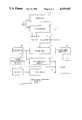
- FIG. 1 shows a schematic block diagram of a pacemaker embodiment provided in accordance with this invention
- FIG. 2 shows a diagram of the strength-duration characteristic featuring rheobase (U o ) and chronaxie (t c );
- FIG. 3 shows a diagram of the relative energy consumption of a pacemaker for pacing a heart at different relative pulse widths presented as multiple times of chronaxie t c .
- FIG. 4 shows a schematic view of an embodiment with an external programming device and a telemetrically programmable pacemaker
- FIG. 5 is a block system diagram of a pacemaker system afforded by this invention.
- FIG. 6 is a block diagram of a pulse monitoring and control embodiment of the invention.
- FIG. 7 is a graph similar to FIG. 2 showing the relationship of different individual pacemaker systems that might be encountered.
- FIG. 8 is a simplified block diagram of a computer controlled energy saving system of this invention using an external monitor programmer under the control of a computer program.
- the essential parts of the cardiac pacemaker 1 are a battery 2, a pulse generator 3, a pacing electrode 4, a sensor 5, an evaluation circuit 6 and a logic circuit 7.
- Sensor 5 is used to detect one or more physiologic parameters of a pacemaker patient. This sensor may be e.g. a temperature sensor, an activity sensor or a combination of several sensors. The signals of this sensor are evaluated in evaluation circuit 6 and are processed in the logic 7 according to given criteria. The logic then calculates the necessary pacing rate which is adequate to the current work load of the pacemaker patient. The logic then drives pulse generator 3 which accordingly delivers pacing pulses to electrode 4.
- Battery 2 supplies the various circuit components of the pacemaker with energy.
- An additional circuit 8 is provided e.g.
- Logic 7 thus determines via selection circuit 9 the voltage amplitude of the pacing pulses for electrode 4. Logic 7 also determines the pulse width of the pacing pulses. On the basis of this calculation, which will be explained below, the logic drives a selection circuit, e.g. in the form of a timer 10, that acts on the pulse generator.
- the described pacemaker additionally determines the effectiveness of a given energy applied via an electrode into the heart as far as a depolarization of the heart muscle is concerned by analyzing the de- and re-polarization of the electro-physiologic cardiac events in order to determine the stimulus threshold characteristic of the rheobase and strength-duration characteristics. This can be done, for example, as follows.
- Logic 7 in response to a program contained therein selected in a threshold determination mode, continuously lowers the pulse width of the pacing pulses by driving pulse generator 3 via selection circuit 10 at a first constant voltage U 1 of the pacing pulses, until no further cardiac activity in response to a first series of pacing pulses is registered. This process is repeated at a second voltage U 2 , or several different voltages.
- the cardiac activity test is performed with the aid of the implanted pacing stimulus electrode 4, which in this case serves simultaneously as a measuring electrode.
- the signals (intracardiac ECG, etc.) are fed to a heart depolarization sensor 12 for detecting the effective and ineffective pulses, which delivers corresponding signals to logic 7, which then determines the strength-duration threshold characteristic.
- the pulse amplitude is shown as voltage U versus pulse width t of the pacing pulses.
- This stimulus threshold curve can be plotted either as a voltage characteristic or as a current characteristic.
- the formula for the stimulus threshold curve corresponds to Equation 2 above.
- the corresponding current characteristic is of the same shape, with the voltage values being replaced by current values.
- the stimulus threshold curve has the form of a hyperbole shifted in the positive direction in the quadrant about the value U o .
- the stimulus threshold e.g.
- Pulse width t 2 is a multiple of pulse width t 1 .
- FIG. 3 shows the energy consumption for the stimulus threshold curve in FIG. 2. It can be seen that the energy consumption is lowest with pulses whose width corresponds to chronaxie, increasing very rapidly with pulses of shorter width and increasing gradually with pulses of greater width than t c . A reduction of pulse widths to values below t c requires a compensatory increase in voltage resulting in a steep increase of the relative energy needed for effective depolarization from the pacing pulses.
- a safety margin in order to achieve reliable pacing of the heart in any case. This can be done by elevating either the voltage amplitude or the pulse width. Due to the determination of the stimulus threshold curve according to the invention and the chronaxie, this safety margin need not exceed 5 to 30% if the threshold is continuously checked by a heart depolarization sensor.
- the pulse width is preferably elevated accordingly, since the energy required for pacing increases relatively slowly in this range. Such an adjustment aimed at safety with the aid of the pulse width is also much easier to do than to change the voltage level, since the timing circuit and pulse width selector can be easily designed with various graduations to deliver a greater plurality of pulse widths than available from a voltage converter.
- circuit for the pacemaker has been described as consisting of discrete elements above, it is of course conceivable for these elements to be functions of a processor, i.e. of the logic in this case.
- the described measurements for determining the rheobase-chronaxie and therefrom the optimal pacing in terms of pulse width and pulse amplitude are performed periodically at intervals which are determined by the logic itself.
- the logic is programmed in such a way that these measurements are performed after implantation of a pacemaker relatively frequently, e.g. every hour or every half a day. This makes it possible to consider changes of the rheobase e.g. due to diurnal variations and especially after implantation of the pacemaker. After a certain time the rheobase stabilizes and the changes in the rheobase are determined essentially by diurnal variations. Once this stabilized phase is reached, the measurements can be performed at larger intervals, which is also controlled by logic 7.
- FIG. 4 shows an external programming device 21 for a pacemaker.
- the external programming device is used to determine the stimulus threshold and strength-duration characteristics of a pacemaker patient by analyzing the digitized intracardiac ECG signal, delivered via electrode 4 to the pacemaker and transmitted from the pacemaker via telemetry means 26 to the telemetry equipment on the programmer's side 25 to be analyzed in heart depolarization sensor 22.
- the necessary measurement circuit 23 and a logic 24 are indicated within programming device 21. From the measured values for the stimulus threshold, the optimal pulse width and pulse amplitude for the pacing pulses of the pacemaker are determined within logic 24 as described above, including a certain safety margin.
- the external programming device also includes telemetry means, transmitter 25 and receiver, for transmitting the calculated data to implanted pacemaker 122.
- Pacemaker 122 has telemetry means 26 for receiving and transmitting coded data information connected to logic 27.
- Logic 27 then controls a pulse generator 28 connected to a pacing electrode 29 in this suggested embodiment.
- the other parts of the pacemaker such as sensors for physiologic parameters and the associated evaluation circuits, have been omitted in this example, in view of the state of the art hereinbefore set forth showing that the implementation of such embodiments is within the ordinary skill of those in this art.
- the pulse width and pulse amplitude values of the pacing pulses are calculated in external programming device 21.
- the external programming device Since the external programming device is aware of the type and model of the pacemaker, it is communicating with those individual data of the specific pacemaker characteristics activated from logic 24, where data is programmed and stored for the individual internal technical energy characteristics for a range of given models. Since each pacemaker type has its own current consumption in the non-pacing mode, variability of pulse width and pulse amplitude, this also has to be considered when calculating an optimal pacing energy in practice. Those practically most efficient energy values can differ from the theoretically calculated values determined only on an electro physiologic basis without considering the practical in-pacemaker programmability situation and energy efficiency. The theoretically optimum value is compared with the best practically achievable optimal energy value and the corresponding pulse width and pulse amplitude is then displayed in a display 30.
- a patient 50 has implanted the pacemaker 51 and the stimulus electrode 52.
- Critical to this pacemaker is the life of implanted battery 53, which supplies primarily energy for the pulse generator 54 for producing the stimulus pulses transmitted to the pacing electrode 52, but also the other power consuming parts of the pacemaker.
- the heart depolarization effectiveness using at least two different voltages and pulse width settings is sensed from a program supplied in the monitoring mode circuitry 154 by means of a sensor 55, in order to determine periodically the minimum threshold pulse energy determined at detector 56 necessary for inducing a heartbeat.
- This monitoring circuit program provides a reduction of pulse energy from pulse generator 54 until the heartbeat becomes marginal to signify the energy threshold.
- the threshold detector according to the above mentioned formulae calculates the threshold at different voltages (U 1 and U 2 ) with the corresponding pulse widths (t 1 and t 2 ), the optimal energy efficiency setting of the two particular voltages and corresponding pulse widths.
- That optimal energy setting is stored in the pulse generating mode block 57 for directing the pulse generator 54 to supply pulses of appropriate amplitude and width for conserving battery drain (with the safety factor added) until a further monitor cycle overrules the stored values.
- the monitor cycle is in effect the usual pacing pulses from lead 58 are blocked and only the monitoring pulses are used as a function of the OR circuit 59.
- the monitoring by means of 54, 55 and 56 is achieved externally with telecommunicating means or internally in the implanted pacemaker. Reduced power drain upon the pacemaker is a significant advantage of the external monitoring unit.
- control logic for the monitoring cycles may be simplified and customized for better control of pacemaker optimum energy, and may have periodic reevaluation cycles built in to take into account possible changing conditions without return to a monitoring station.
- monitoring cycles for optional setting for energy efficiency it should be clearly understood that a heart depolarization sensor, if incorporated into the pacemaker, is constantly running in order to allow a minimal low energy setting close to the strength-duration curve without a major safety margin, thereto to save additional battery energy.
- FIG. 6 provides an operational flow sequence for the threshold detection and pulse control features of this invention.
- This circuit accordingly at 61, 62 provides two pulses A and B of different known energy levels from pulse generator 54 when the sampling mode 60 is in effect.
- these two pulses with the help of the heart activity sensor 63 will determine the minimum energy characteristic and result in the derivation of an algorithm 64 for a particular patient and pacemaker system.
- the derived algorithm therefore establishes an operating pulse energy level, as before stated, preferably a variation of pulse width in circuit 65 for control of the pacing pulses formed in generator 54 as transmitted to the stimulus electrode 52 by way of OR circuit 66 which also transmits the pulses A and B alternatively to the stimulus electrode during the sampling period.
- FIG. 7 the variations between different implanted electrode are shown by the curves 70A, 70 and 70B related to the time of chronaxie t c .
- the various voltage operation levels U for the respective pacemaker systems are indicated at 72, 73 and 74 for example.
- FIG. 8 identifies the hereinbefore described system with an external monitor-programmer 83 operating over a communication link 80 to send information 82 to the implant pacemaker and receive it 81 from the pacemaker.
- a microprocessor 84 in the programmer unit may be programmed for the proper control logic and may contain in its memory the stored data relating to the technical characteristics of a range of pacemaker models.
Abstract
Description
W=U.sup.2 ×t/R (1).
U=U.sub.o (1+t.sub.c /t) (2)
W(t.sub.c)=4U.sub.o.sup.2 t.sub.c /R (3)
W=12.1U.sub.o.sup.2 t.sub.c /R.
U.sub.1 =U.sub.o (1+t.sub.c /t.sub.1) and U.sub.2 =(U.sub.o (1+t.sub.c /kt.sub.1) (4)
U.sub.o =(kU.sub.2 -U.sub.1)/(k-1) (5)
t.sub.c :=(U.sub.1 -U.sub.o)t.sub.1 /U.sub.o (6)
Claims (18)
Applications Claiming Priority (2)
| Application Number | Priority Date | Filing Date | Title |
|---|---|---|---|
| DE3816042A DE3816042A1 (en) | 1988-05-10 | 1988-05-10 | ENERGY SAVING HEART PACEMAKER |
| DE3816042 | 1988-05-10 |
Publications (1)
| Publication Number | Publication Date |
|---|---|
| US4979507A true US4979507A (en) | 1990-12-25 |
Family
ID=6354121
Family Applications (1)
| Application Number | Title | Priority Date | Filing Date |
|---|---|---|---|
| US07/347,435 Expired - Lifetime US4979507A (en) | 1988-05-10 | 1989-05-03 | Energy saving cardiac pacemaker |
Country Status (2)
| Country | Link |
|---|---|
| US (1) | US4979507A (en) |
| DE (1) | DE3816042A1 (en) |
Cited By (114)
| Publication number | Priority date | Publication date | Assignee | Title |
|---|---|---|---|---|
| US5165404A (en) * | 1990-04-24 | 1992-11-24 | Siemens Aktiengesellschaft | Biological tissue stimulation device with control means for determining stimulation sensitivity calculation timing |
| US5184617A (en) * | 1990-06-05 | 1993-02-09 | Staodyn, Inc. | Output pulse compensation for therapeutic-type electronic devices |
| US5292341A (en) * | 1992-03-02 | 1994-03-08 | Siemens Pacesetter, Inc. | Method and system for determining and automatically adjusting the sensor parameters of a rate-responsive pacemaker |
| US5320643A (en) * | 1992-10-06 | 1994-06-14 | Medtronic, Inc. | Automatic cardiac capture restoration and threshold-seeking method and apparatus |
| US5391191A (en) * | 1990-04-24 | 1995-02-21 | Siemens Aktiengesellschaft | Device for tissue stimulation |
| US5431693A (en) * | 1993-12-10 | 1995-07-11 | Intermedics, Inc. | Method of verifying capture of the heart by a pacemaker |
| US5441524A (en) * | 1993-08-30 | 1995-08-15 | Medtronic, Inc. | Energy efficient multiple sensor cardiac pacemaker |
| US5443485A (en) * | 1993-09-08 | 1995-08-22 | Intermedics, Inc. | Apparatus and method for capture detection in a cardiac stimulator |
| US5447525A (en) * | 1993-09-15 | 1995-09-05 | Medtronic, Inc. | Pacemaker which adapts to minimize current drain and provide desired capture safety margin |
| US5456692A (en) * | 1993-09-03 | 1995-10-10 | Pacesetter, Inc. | System and method for noninvasively altering the function of an implanted pacemaker |
| US5718720A (en) * | 1996-12-13 | 1998-02-17 | Sulzer Intermedics Inc. | Implantable cardiac stimulator with capture detection and impedance based autotuning of capture detection |
| US5735883A (en) * | 1996-12-13 | 1998-04-07 | Sulzer Intermedics Inc. | Implantable cardiac stimulator with impedance based autothreshold |
| US5843137A (en) * | 1994-11-30 | 1998-12-01 | Medtronic, Inc. | Capture detection method |
| US5861013A (en) * | 1997-04-29 | 1999-01-19 | Medtronic Inc. | Peak tracking capture detection circuit and method |
| US5871512A (en) * | 1997-04-29 | 1999-02-16 | Medtronic, Inc. | Microprocessor capture detection circuit and method |
| US5954756A (en) * | 1998-04-09 | 1999-09-21 | Medtronic, Inc. | Microprocessor capture detection circuit and method |
| WO2000004947A3 (en) * | 1998-07-20 | 2000-06-15 | Impulse Dynamics Nv | Pacing with hemodynamic enhancement |
| US20020013613A1 (en) * | 1999-07-07 | 2002-01-31 | Markus Haller | System and method for remote programming of an implantable medical device |
| US6456879B1 (en) | 2000-05-15 | 2002-09-24 | Pacesetter, Inc. | Method and device for optimally altering stimulation energy to maintain capture of cardiac tissue |
| US6549806B1 (en) | 2000-05-15 | 2003-04-15 | Pacesetter, Inc. | Implantable dual site cardiac stimulation device having independent automatic capture capability |
| US6615082B1 (en) | 2000-05-15 | 2003-09-02 | Pacesetter, Inc. | Method and device for optimally altering stimulation energy to maintain capture of cardiac tissue |
| US6618621B1 (en) | 1998-05-27 | 2003-09-09 | St. Jude Medical Ab | Pacemaker with stimulation threshold measuring |
| US6648823B2 (en) | 2001-07-31 | 2003-11-18 | Medtronic, Inc. | Method and system of follow-up support for a medical device |
| US20040138710A1 (en) * | 1996-01-11 | 2004-07-15 | Itsik Shemer | Signal delivery through the right ventricular septum |
| WO2005086063A3 (en) * | 2004-02-27 | 2006-03-30 | Koninkl Philips Electronics Nv | Method and system to minimize power consumption by using staged life-threatening arrhythmia detection algorithm |
| US7027863B1 (en) | 1999-10-25 | 2006-04-11 | Impulse Dynamics N.V. | Device for cardiac therapy |
| US7062318B2 (en) | 1996-01-08 | 2006-06-13 | Impulse Dynamics (Israel) Ltd | Electrical muscle controller |
| US7111179B1 (en) | 2001-10-11 | 2006-09-19 | In-Hand Electronics, Inc. | Method and apparatus for optimizing performance and battery life of electronic devices based on system and application parameters |
| US7158826B1 (en) * | 2003-04-30 | 2007-01-02 | Pacesetter, Inc. | System and method for generating pain inhibition pulses using an implantable cardiac stimulation device |
| US7167748B2 (en) | 1996-01-08 | 2007-01-23 | Impulse Dynamics Nv | Electrical muscle controller |
| US20080103559A1 (en) * | 2006-10-26 | 2008-05-01 | Advanced Bionics Corporation | Method of maintaining intensity output while adjusting pulse width or amplitude |
| US20090043352A1 (en) * | 2007-08-07 | 2009-02-12 | Brooke M Jason | Method and apparatus to perform electrode combination selection |
| US7647102B2 (en) | 1999-10-25 | 2010-01-12 | Impulse Dynamics N.V. | Cardiac contractility modulation device having anti-arrhythmic capabilities and method of operating thereof |
| US7678573B2 (en) | 1999-02-04 | 2010-03-16 | Pluristem Ltd. | Method of preparing a conditioned medium from a confluent stromal cell culture |
| US7774064B2 (en) | 2003-12-12 | 2010-08-10 | Cardiac Pacemakers, Inc. | Cardiac response classification using retriggerable classification windows |
| US7840264B1 (en) | 1996-08-19 | 2010-11-23 | Mr3 Medical, Llc | System and method for breaking reentry circuits by cooling cardiac tissue |
| US7840262B2 (en) | 2003-03-10 | 2010-11-23 | Impulse Dynamics Nv | Apparatus and method for delivering electrical signals to modify gene expression in cardiac tissue |
| US7843439B2 (en) | 2003-02-10 | 2010-11-30 | N-Trig Ltd. | Touch detection for a digitizer |
| US7908003B1 (en) | 1996-08-19 | 2011-03-15 | Mr3 Medical Llc | System and method for treating ischemia by improving cardiac efficiency |
| US7953481B1 (en) | 1999-10-25 | 2011-05-31 | Impulse Dynamics N.V. | Anti-arrhythmic device and a method of delivering anti-arrhythmic cardiac therapy |
| US8019421B2 (en) | 1999-03-05 | 2011-09-13 | Metacure Limited | Blood glucose level control |
| US8145296B2 (en) | 2005-04-28 | 2012-03-27 | Cardiac Pacemakers, Inc. | Adaptive windowing for cardiac waveform discrimination |
| US8145310B2 (en) | 2003-12-11 | 2012-03-27 | Cardiac Pacemakers, Inc. | Non-captured intrinsic discrimination in cardiac pacing response classification |
| US8185202B2 (en) | 2005-04-26 | 2012-05-22 | Cardiac Pacemakers, Inc. | Implantable cardiac device for reduced phrenic nerve stimulation |
| US20120136408A1 (en) * | 2010-05-27 | 2012-05-31 | Duke University | Waveform shapes for treating neurological disorders optimized for energy efficiency |
| US8209013B2 (en) * | 2006-09-14 | 2012-06-26 | Cardiac Pacemakers, Inc. | Therapeutic electrical stimulation that avoids undesirable activation |
| US8244371B2 (en) | 2005-03-18 | 2012-08-14 | Metacure Limited | Pancreas lead |
| US8265736B2 (en) | 2007-08-07 | 2012-09-11 | Cardiac Pacemakers, Inc. | Method and apparatus to perform electrode combination selection |
| US8321013B2 (en) | 1996-01-08 | 2012-11-27 | Impulse Dynamics, N.V. | Electrical muscle controller and pacing with hemodynamic enhancement |
| US8346363B2 (en) | 1999-03-05 | 2013-01-01 | Metacure Limited | Blood glucose level control |
| US8352031B2 (en) | 2004-03-10 | 2013-01-08 | Impulse Dynamics Nv | Protein activity modification |
| US8521284B2 (en) | 2003-12-12 | 2013-08-27 | Cardiac Pacemakers, Inc. | Cardiac response classification using multisite sensing and pacing |
| US8548583B2 (en) | 2004-03-10 | 2013-10-01 | Impulse Dynamics Nv | Protein activity modification |
| US8565879B2 (en) | 2010-03-30 | 2013-10-22 | Cardiac Pacemakers, Inc. | Method and apparatus for pacing safety margin |
| US8649866B2 (en) | 2008-02-14 | 2014-02-11 | Cardiac Pacemakers, Inc. | Method and apparatus for phrenic stimulation detection |
| US8666495B2 (en) | 1999-03-05 | 2014-03-04 | Metacure Limited | Gastrointestinal methods and apparatus for use in treating disorders and controlling blood sugar |
| US8688216B2 (en) | 2011-11-29 | 2014-04-01 | Cardiac Pacemakers, Inc. | Autothreshold with sensing from pacing cathode |
| US8700161B2 (en) | 1999-03-05 | 2014-04-15 | Metacure Limited | Blood glucose level control |
| US8792985B2 (en) | 2003-07-21 | 2014-07-29 | Metacure Limited | Gastrointestinal methods and apparatus for use in treating disorders and controlling blood sugar |
| US8825152B2 (en) | 1996-01-08 | 2014-09-02 | Impulse Dynamics, N.V. | Modulation of intracellular calcium concentration using non-excitatory electrical signals applied to the tissue |
| US20140323882A1 (en) * | 2013-04-30 | 2014-10-30 | Medtronic, Inc. | Systems, methods, and interfaces for identifying optimal electrical vectors |
| US8934975B2 (en) | 2010-02-01 | 2015-01-13 | Metacure Limited | Gastrointestinal electrical therapy |
| US9008772B2 (en) | 2011-11-29 | 2015-04-14 | Cardiac Pacemakers, Inc. | Hybrid autothreshold |
| US9101765B2 (en) | 1999-03-05 | 2015-08-11 | Metacure Limited | Non-immediate effects of therapy |
| US9289618B1 (en) | 1996-01-08 | 2016-03-22 | Impulse Dynamics Nv | Electrical muscle controller |
| EP3042693A1 (en) | 2015-01-12 | 2016-07-13 | Sorin CRM SAS | Active implantable medical device, such as an autonomous capsule, with dynamic optimisation of the energy of stimulation pulses |
| US9474457B2 (en) | 2013-06-12 | 2016-10-25 | Medtronic, Inc. | Metrics of electrical dyssynchrony and electrical activation patterns from surface ECG electrodes |
| US9586050B2 (en) | 2014-08-15 | 2017-03-07 | Medtronic, Inc. | Systems and methods for configuration of atrioventricular interval |
| US9586052B2 (en) | 2014-08-15 | 2017-03-07 | Medtronic, Inc. | Systems and methods for evaluating cardiac therapy |
| US9591982B2 (en) | 2014-07-31 | 2017-03-14 | Medtronic, Inc. | Systems and methods for evaluating cardiac therapy |
| US9713723B2 (en) | 1996-01-11 | 2017-07-25 | Impulse Dynamics Nv | Signal delivery through the right ventricular septum |
| US9764143B2 (en) | 2014-08-15 | 2017-09-19 | Medtronic, Inc. | Systems and methods for configuration of interventricular interval |
| US9776009B2 (en) | 2014-03-20 | 2017-10-03 | Medtronic, Inc. | Non-invasive detection of phrenic nerve stimulation |
| US9821158B2 (en) | 2005-02-17 | 2017-11-21 | Metacure Limited | Non-immediate effects of therapy |
| US9877789B2 (en) | 2013-06-12 | 2018-01-30 | Medtronic, Inc. | Implantable electrode location selection |
| US9924884B2 (en) | 2013-04-30 | 2018-03-27 | Medtronic, Inc. | Systems, methods, and interfaces for identifying effective electrodes |
| US9931503B2 (en) | 2003-03-10 | 2018-04-03 | Impulse Dynamics Nv | Protein activity modification |
| US9962097B2 (en) | 2011-05-03 | 2018-05-08 | Medtronic, Inc. | Assessing intra-cardiac activation patterns and electrical dyssynchrony |
| US9986928B2 (en) | 2013-12-09 | 2018-06-05 | Medtronic, Inc. | Noninvasive cardiac therapy evaluation |
| US10251555B2 (en) | 2013-06-12 | 2019-04-09 | Medtronic, Inc. | Implantable electrode location selection |
| CN109952129A (en) * | 2016-11-09 | 2019-06-28 | 心脏起搏器股份公司 | The system, apparatus and method of cardiac pacing pulse parameter are set for cardiac pacing device |
| US10390756B2 (en) | 2016-02-22 | 2019-08-27 | Electronics And Telecommunications Research Institute | Bio-stimulating and bio-signal measuring circuit |
| US10433746B2 (en) | 2017-12-22 | 2019-10-08 | Regents Of The University Of Minnesota | Systems and methods for anterior and posterior electrode signal analysis |
| US10492705B2 (en) | 2017-12-22 | 2019-12-03 | Regents Of The University Of Minnesota | Anterior and posterior electrode signals |
| US10532213B2 (en) | 2017-03-03 | 2020-01-14 | Medtronic, Inc. | Criteria for determination of local tissue latency near pacing electrode |
| US10617318B2 (en) | 2018-02-27 | 2020-04-14 | Medtronic, Inc. | Mapping electrical activity on a model heart |
| US10668290B2 (en) | 2018-03-01 | 2020-06-02 | Medtronic, Inc. | Delivery of pacing therapy by a cardiac pacing device |
| US10688306B2 (en) | 2013-12-23 | 2020-06-23 | Deep Brain Innovations LLC | Programming systems for deep brain stimulator system |
| US10716943B2 (en) | 2008-10-03 | 2020-07-21 | Duke University | Non-regular electrical stimulation patterns for treating neurological disorders |
| US10773085B2 (en) | 2017-03-15 | 2020-09-15 | Medtronic, Inc. | QRS offset and onset determination |
| US10773084B2 (en) | 2008-10-03 | 2020-09-15 | Duke University | Non-regular electrical stimulation patterns designed with a cost function for treating neurological disorders |
| US10780281B2 (en) | 2018-03-23 | 2020-09-22 | Medtronic, Inc. | Evaluation of ventricle from atrium pacing therapy |
| US10780279B2 (en) | 2016-02-26 | 2020-09-22 | Medtronic, Inc. | Methods and systems of optimizing right ventricular only pacing for patients with respect to an atrial event and left ventricular event |
| US10786167B2 (en) | 2017-12-22 | 2020-09-29 | Medtronic, Inc. | Ectopic beat-compensated electrical heterogeneity information |
| US10799703B2 (en) | 2017-12-22 | 2020-10-13 | Medtronic, Inc. | Evaluation of his bundle pacing therapy |
| US10918863B2 (en) | 2017-07-28 | 2021-02-16 | Medtronic, Inc. | Generating activation times |
| US10918870B2 (en) | 2018-03-07 | 2021-02-16 | Medtronic, Inc. | Atrial lead placement for treatment of atrial dyssynchrony |
| US10940321B2 (en) | 2018-06-01 | 2021-03-09 | Medtronic, Inc. | Systems, methods, and interfaces for use in cardiac evaluation |
| US11013924B2 (en) | 2008-10-03 | 2021-05-25 | Duke University | Non-regular electrical stimulation patterns for treating neurological disorders |
| US11219769B2 (en) | 2016-02-26 | 2022-01-11 | Medtronic, Inc. | Noninvasive methods and systems of determining the extent of tissue capture from cardiac pacing |
| US11253178B2 (en) | 2015-01-29 | 2022-02-22 | Medtronic, Inc. | Noninvasive assessment of cardiac resynchronization therapy |
| US11285312B2 (en) | 2018-03-29 | 2022-03-29 | Medtronic, Inc. | Left ventricular assist device adjustment and evaluation |
| US11304641B2 (en) | 2018-06-01 | 2022-04-19 | Medtronic, Inc. | Systems, methods, and interfaces for use in cardiac evaluation |
| US11419539B2 (en) | 2017-12-22 | 2022-08-23 | Regents Of The University Of Minnesota | QRS onset and offset times and cycle selection using anterior and posterior electrode signals |
| US11439815B2 (en) | 2003-03-10 | 2022-09-13 | Impulse Dynamics Nv | Protein activity modification |
| US11471678B2 (en) | 2017-07-28 | 2022-10-18 | Medtronic, Inc. | Cardiac cycle selection |
| US11497431B2 (en) | 2019-10-09 | 2022-11-15 | Medtronic, Inc. | Systems and methods for configuring cardiac therapy |
| US11547858B2 (en) | 2019-03-29 | 2023-01-10 | Medtronic, Inc. | Systems, methods, and devices for adaptive cardiac therapy |
| US11583680B2 (en) | 2013-05-22 | 2023-02-21 | Deep Brain Innovations LLC | Deep brain stimulator and method of use |
| US11633605B2 (en) | 2008-10-03 | 2023-04-25 | Duke University | Non-regular electrical stimulation patterns for treating neurological disorders |
| US11642533B2 (en) | 2019-11-04 | 2023-05-09 | Medtronic, Inc. | Systems and methods for evaluating cardiac therapy |
| US11697025B2 (en) | 2019-03-29 | 2023-07-11 | Medtronic, Inc. | Cardiac conduction system capture |
| US11779768B2 (en) | 2004-03-10 | 2023-10-10 | Impulse Dynamics Nv | Protein activity modification |
| US11813464B2 (en) | 2020-07-31 | 2023-11-14 | Medtronic, Inc. | Cardiac conduction system evaluation |
Families Citing this family (2)
| Publication number | Priority date | Publication date | Assignee | Title |
|---|---|---|---|---|
| US4984572A (en) * | 1988-08-18 | 1991-01-15 | Leonard Bloom | Hemodynamically responsive system for and method of treating a malfunctioning heart |
| JPH06503973A (en) * | 1990-08-14 | 1994-05-12 | メドトロニック インコーポレーテッド | Rate-responsive pacemakers and how to optimize their operation |
Citations (9)
| Publication number | Priority date | Publication date | Assignee | Title |
|---|---|---|---|---|
| US3517663A (en) * | 1968-04-15 | 1970-06-30 | Gen Electric | Threshold analyzer for an implanted heart stimulator |
| US3669120A (en) * | 1969-07-11 | 1972-06-13 | Rovsing As Christian | Device for starting or stimulating heart contractions |
| US3713449A (en) * | 1970-08-31 | 1973-01-30 | P Mulier | Cardiac pacer with externally controllable variable width output pulse |
| US3717152A (en) * | 1967-11-16 | 1973-02-20 | Vitatron Nv | Cardiac pacemaker |
| US3757792A (en) * | 1971-11-11 | 1973-09-11 | Medtronic Inc | Automatic threshold compensating demand pacemaker |
| US3777762A (en) * | 1970-12-22 | 1973-12-11 | Rovsing As Christian | Pacemaker with continuously adjustable output amplitude |
| US3949758A (en) * | 1974-08-01 | 1976-04-13 | Medtronic, Inc. | Automatic threshold following cardiac pacer |
| US4340063A (en) * | 1980-01-02 | 1982-07-20 | Empi, Inc. | Stimulation device |
| US4571589A (en) * | 1982-11-22 | 1986-02-18 | Cordis Corporation | Biomedical implant with high speed, low power two-way telemetry |
Family Cites Families (1)
| Publication number | Priority date | Publication date | Assignee | Title |
|---|---|---|---|---|
| US3920024A (en) * | 1973-04-16 | 1975-11-18 | Vitatron Medical Bv | Threshold tracking system and method for stimulating a physiological system |
-
1988
- 1988-05-10 DE DE3816042A patent/DE3816042A1/en not_active Ceased
-
1989
- 1989-05-03 US US07/347,435 patent/US4979507A/en not_active Expired - Lifetime
Patent Citations (9)
| Publication number | Priority date | Publication date | Assignee | Title |
|---|---|---|---|---|
| US3717152A (en) * | 1967-11-16 | 1973-02-20 | Vitatron Nv | Cardiac pacemaker |
| US3517663A (en) * | 1968-04-15 | 1970-06-30 | Gen Electric | Threshold analyzer for an implanted heart stimulator |
| US3669120A (en) * | 1969-07-11 | 1972-06-13 | Rovsing As Christian | Device for starting or stimulating heart contractions |
| US3713449A (en) * | 1970-08-31 | 1973-01-30 | P Mulier | Cardiac pacer with externally controllable variable width output pulse |
| US3777762A (en) * | 1970-12-22 | 1973-12-11 | Rovsing As Christian | Pacemaker with continuously adjustable output amplitude |
| US3757792A (en) * | 1971-11-11 | 1973-09-11 | Medtronic Inc | Automatic threshold compensating demand pacemaker |
| US3949758A (en) * | 1974-08-01 | 1976-04-13 | Medtronic, Inc. | Automatic threshold following cardiac pacer |
| US4340063A (en) * | 1980-01-02 | 1982-07-20 | Empi, Inc. | Stimulation device |
| US4571589A (en) * | 1982-11-22 | 1986-02-18 | Cordis Corporation | Biomedical implant with high speed, low power two-way telemetry |
Cited By (174)
| Publication number | Priority date | Publication date | Assignee | Title |
|---|---|---|---|---|
| US5391191A (en) * | 1990-04-24 | 1995-02-21 | Siemens Aktiengesellschaft | Device for tissue stimulation |
| US5165404A (en) * | 1990-04-24 | 1992-11-24 | Siemens Aktiengesellschaft | Biological tissue stimulation device with control means for determining stimulation sensitivity calculation timing |
| US5184617A (en) * | 1990-06-05 | 1993-02-09 | Staodyn, Inc. | Output pulse compensation for therapeutic-type electronic devices |
| USRE35987E (en) * | 1990-06-05 | 1998-12-08 | Staodyn, Inc. | Output pulse compensation for therapeutic-type electronic devices |
| US5292341A (en) * | 1992-03-02 | 1994-03-08 | Siemens Pacesetter, Inc. | Method and system for determining and automatically adjusting the sensor parameters of a rate-responsive pacemaker |
| US5320643A (en) * | 1992-10-06 | 1994-06-14 | Medtronic, Inc. | Automatic cardiac capture restoration and threshold-seeking method and apparatus |
| US5441524A (en) * | 1993-08-30 | 1995-08-15 | Medtronic, Inc. | Energy efficient multiple sensor cardiac pacemaker |
| US5456692A (en) * | 1993-09-03 | 1995-10-10 | Pacesetter, Inc. | System and method for noninvasively altering the function of an implanted pacemaker |
| US5443485A (en) * | 1993-09-08 | 1995-08-22 | Intermedics, Inc. | Apparatus and method for capture detection in a cardiac stimulator |
| US5447525A (en) * | 1993-09-15 | 1995-09-05 | Medtronic, Inc. | Pacemaker which adapts to minimize current drain and provide desired capture safety margin |
| US5431693A (en) * | 1993-12-10 | 1995-07-11 | Intermedics, Inc. | Method of verifying capture of the heart by a pacemaker |
| US5843137A (en) * | 1994-11-30 | 1998-12-01 | Medtronic, Inc. | Capture detection method |
| US7167748B2 (en) | 1996-01-08 | 2007-01-23 | Impulse Dynamics Nv | Electrical muscle controller |
| US8321013B2 (en) | 1996-01-08 | 2012-11-27 | Impulse Dynamics, N.V. | Electrical muscle controller and pacing with hemodynamic enhancement |
| US8260416B2 (en) | 1996-01-08 | 2012-09-04 | Impulse Dynamics, N.V. | Electrical muscle controller |
| US8825152B2 (en) | 1996-01-08 | 2014-09-02 | Impulse Dynamics, N.V. | Modulation of intracellular calcium concentration using non-excitatory electrical signals applied to the tissue |
| US7062318B2 (en) | 1996-01-08 | 2006-06-13 | Impulse Dynamics (Israel) Ltd | Electrical muscle controller |
| US9289618B1 (en) | 1996-01-08 | 2016-03-22 | Impulse Dynamics Nv | Electrical muscle controller |
| US8301247B2 (en) | 1996-01-08 | 2012-10-30 | Impulse Dynamics, N.V. | Electrical muscle controller |
| US8306616B2 (en) | 1996-01-08 | 2012-11-06 | Impulse Dynamics, N.V. | Electrical muscle controller |
| US8306617B2 (en) | 1996-01-08 | 2012-11-06 | Impulse Dynamics N.V. | Electrical muscle controller |
| US8311629B2 (en) | 1996-01-08 | 2012-11-13 | Impulse Dynamics, N.V. | Electrical muscle controller |
| US7187970B2 (en) | 1996-01-11 | 2007-03-06 | Impulse Dynamics (Israel) Ltd | Excitable tissue control signal delivery to the right ventricular septum |
| US20040138710A1 (en) * | 1996-01-11 | 2004-07-15 | Itsik Shemer | Signal delivery through the right ventricular septum |
| US9713723B2 (en) | 1996-01-11 | 2017-07-25 | Impulse Dynamics Nv | Signal delivery through the right ventricular septum |
| US7908003B1 (en) | 1996-08-19 | 2011-03-15 | Mr3 Medical Llc | System and method for treating ischemia by improving cardiac efficiency |
| US7840264B1 (en) | 1996-08-19 | 2010-11-23 | Mr3 Medical, Llc | System and method for breaking reentry circuits by cooling cardiac tissue |
| WO1998025672A1 (en) | 1996-12-13 | 1998-06-18 | Intermedics Inc. | Implantable cardiac stimulator with capture detection and impedance based autotuning of capture detection |
| US5735883A (en) * | 1996-12-13 | 1998-04-07 | Sulzer Intermedics Inc. | Implantable cardiac stimulator with impedance based autothreshold |
| US5718720A (en) * | 1996-12-13 | 1998-02-17 | Sulzer Intermedics Inc. | Implantable cardiac stimulator with capture detection and impedance based autotuning of capture detection |
| US6144881A (en) * | 1997-04-29 | 2000-11-07 | Medtronic, Inc. | Capture detection circuit for pulses and physiologic signals |
| US6134473A (en) * | 1997-04-29 | 2000-10-17 | Medtronic, Inc. | Microprocessor capture detection circuit and method |
| US5873898A (en) * | 1997-04-29 | 1999-02-23 | Medtronic, Inc. | Microprocessor capture detection circuit and method |
| US5871512A (en) * | 1997-04-29 | 1999-02-16 | Medtronic, Inc. | Microprocessor capture detection circuit and method |
| US5861013A (en) * | 1997-04-29 | 1999-01-19 | Medtronic Inc. | Peak tracking capture detection circuit and method |
| US5954756A (en) * | 1998-04-09 | 1999-09-21 | Medtronic, Inc. | Microprocessor capture detection circuit and method |
| US6618621B1 (en) | 1998-05-27 | 2003-09-09 | St. Jude Medical Ab | Pacemaker with stimulation threshold measuring |
| US7460907B1 (en) | 1998-07-20 | 2008-12-02 | Impulse Dynamics N.V. | Pacing with hemodynamic enhancement |
| WO2000004947A3 (en) * | 1998-07-20 | 2000-06-15 | Impulse Dynamics Nv | Pacing with hemodynamic enhancement |
| US7678573B2 (en) | 1999-02-04 | 2010-03-16 | Pluristem Ltd. | Method of preparing a conditioned medium from a confluent stromal cell culture |
| US8700161B2 (en) | 1999-03-05 | 2014-04-15 | Metacure Limited | Blood glucose level control |
| US8666495B2 (en) | 1999-03-05 | 2014-03-04 | Metacure Limited | Gastrointestinal methods and apparatus for use in treating disorders and controlling blood sugar |
| US9101765B2 (en) | 1999-03-05 | 2015-08-11 | Metacure Limited | Non-immediate effects of therapy |
| US8019421B2 (en) | 1999-03-05 | 2011-09-13 | Metacure Limited | Blood glucose level control |
| US8346363B2 (en) | 1999-03-05 | 2013-01-01 | Metacure Limited | Blood glucose level control |
| US7181505B2 (en) * | 1999-07-07 | 2007-02-20 | Medtronic, Inc. | System and method for remote programming of an implantable medical device |
| US20020013613A1 (en) * | 1999-07-07 | 2002-01-31 | Markus Haller | System and method for remote programming of an implantable medical device |
| US7647102B2 (en) | 1999-10-25 | 2010-01-12 | Impulse Dynamics N.V. | Cardiac contractility modulation device having anti-arrhythmic capabilities and method of operating thereof |
| US7027863B1 (en) | 1999-10-25 | 2006-04-11 | Impulse Dynamics N.V. | Device for cardiac therapy |
| US7953481B1 (en) | 1999-10-25 | 2011-05-31 | Impulse Dynamics N.V. | Anti-arrhythmic device and a method of delivering anti-arrhythmic cardiac therapy |
| US6615082B1 (en) | 2000-05-15 | 2003-09-02 | Pacesetter, Inc. | Method and device for optimally altering stimulation energy to maintain capture of cardiac tissue |
| US6549806B1 (en) | 2000-05-15 | 2003-04-15 | Pacesetter, Inc. | Implantable dual site cardiac stimulation device having independent automatic capture capability |
| US6456879B1 (en) | 2000-05-15 | 2002-09-24 | Pacesetter, Inc. | Method and device for optimally altering stimulation energy to maintain capture of cardiac tissue |
| US6648823B2 (en) | 2001-07-31 | 2003-11-18 | Medtronic, Inc. | Method and system of follow-up support for a medical device |
| US7111179B1 (en) | 2001-10-11 | 2006-09-19 | In-Hand Electronics, Inc. | Method and apparatus for optimizing performance and battery life of electronic devices based on system and application parameters |
| US7843439B2 (en) | 2003-02-10 | 2010-11-30 | N-Trig Ltd. | Touch detection for a digitizer |
| US8228311B2 (en) | 2003-02-10 | 2012-07-24 | N-Trig Ltd. | Touch detection for a digitizer |
| US9931503B2 (en) | 2003-03-10 | 2018-04-03 | Impulse Dynamics Nv | Protein activity modification |
| US8326416B2 (en) | 2003-03-10 | 2012-12-04 | Impulse Dynamics Nv | Apparatus and method for delivering electrical signals to modify gene expression in cardiac tissue |
| US11439815B2 (en) | 2003-03-10 | 2022-09-13 | Impulse Dynamics Nv | Protein activity modification |
| US7840262B2 (en) | 2003-03-10 | 2010-11-23 | Impulse Dynamics Nv | Apparatus and method for delivering electrical signals to modify gene expression in cardiac tissue |
| US7158826B1 (en) * | 2003-04-30 | 2007-01-02 | Pacesetter, Inc. | System and method for generating pain inhibition pulses using an implantable cardiac stimulation device |
| US8792985B2 (en) | 2003-07-21 | 2014-07-29 | Metacure Limited | Gastrointestinal methods and apparatus for use in treating disorders and controlling blood sugar |
| US8145310B2 (en) | 2003-12-11 | 2012-03-27 | Cardiac Pacemakers, Inc. | Non-captured intrinsic discrimination in cardiac pacing response classification |
| US9008771B2 (en) | 2003-12-11 | 2015-04-14 | Cardiac Pacemakers, Inc. | Non-captured intrinsic discrimination in cardiac pacing response classification |
| US9308375B2 (en) | 2003-12-12 | 2016-04-12 | Cardiac Pacemakers, Inc. | Cardiac response classification using multisite sensing and pacing |
| US8843199B2 (en) | 2003-12-12 | 2014-09-23 | Cardiac Pacemakers, Inc. | Cardiac response classification using multisite sensing and pacing |
| US8521284B2 (en) | 2003-12-12 | 2013-08-27 | Cardiac Pacemakers, Inc. | Cardiac response classification using multisite sensing and pacing |
| US7774064B2 (en) | 2003-12-12 | 2010-08-10 | Cardiac Pacemakers, Inc. | Cardiac response classification using retriggerable classification windows |
| US10898142B2 (en) | 2003-12-12 | 2021-01-26 | Cardiac Pacemakers, Inc. | Cardiac response classification using retriggerable classification windows |
| US9993205B2 (en) | 2003-12-12 | 2018-06-12 | Cardiac Pacemakers, Inc. | Cardiac response classification using retriggerable classification windows |
| WO2005086063A3 (en) * | 2004-02-27 | 2006-03-30 | Koninkl Philips Electronics Nv | Method and system to minimize power consumption by using staged life-threatening arrhythmia detection algorithm |
| US10352948B2 (en) | 2004-03-10 | 2019-07-16 | Impulse Dynamics Nv | Protein activity modification |
| US8548583B2 (en) | 2004-03-10 | 2013-10-01 | Impulse Dynamics Nv | Protein activity modification |
| US8352031B2 (en) | 2004-03-10 | 2013-01-08 | Impulse Dynamics Nv | Protein activity modification |
| US11779768B2 (en) | 2004-03-10 | 2023-10-10 | Impulse Dynamics Nv | Protein activity modification |
| US9821158B2 (en) | 2005-02-17 | 2017-11-21 | Metacure Limited | Non-immediate effects of therapy |
| US8244371B2 (en) | 2005-03-18 | 2012-08-14 | Metacure Limited | Pancreas lead |
| US8185202B2 (en) | 2005-04-26 | 2012-05-22 | Cardiac Pacemakers, Inc. | Implantable cardiac device for reduced phrenic nerve stimulation |
| US8260421B2 (en) | 2005-04-26 | 2012-09-04 | Cardiac Pacemakers, Inc. | Method for reducing phrenic nerve stimulation |
| US8145296B2 (en) | 2005-04-28 | 2012-03-27 | Cardiac Pacemakers, Inc. | Adaptive windowing for cardiac waveform discrimination |
| US8209013B2 (en) * | 2006-09-14 | 2012-06-26 | Cardiac Pacemakers, Inc. | Therapeutic electrical stimulation that avoids undesirable activation |
| US9943694B2 (en) | 2006-10-26 | 2018-04-17 | Boston Scientific Neuromodulation Corporation | System and method to automatically maintain electrical stimulation intensity |
| US9352161B2 (en) * | 2006-10-26 | 2016-05-31 | Boston Scientific Neuromodulation Corporation | Method of maintaining intensity output while adjusting pulse width or amplitude |
| US20080103559A1 (en) * | 2006-10-26 | 2008-05-01 | Advanced Bionics Corporation | Method of maintaining intensity output while adjusting pulse width or amplitude |
| US11439831B2 (en) | 2006-10-26 | 2022-09-13 | Boston Scientific Neuromodulation Corporation | Automatic adjustment to maintain evoked potential feature |
| AU2007308873B2 (en) * | 2006-10-26 | 2012-03-01 | Boston Scientific Neuromodulation Corporation | Method of maintaining intensity output while adjusting pulse width or amplitude |
| US10456585B2 (en) | 2006-10-26 | 2019-10-29 | Boston Scientific Neuromodulation Corporation | System and method to automatically maintain electrical stimulation intensity |
| US9008775B2 (en) | 2007-08-07 | 2015-04-14 | Cardiac Pacemakers, Inc. | Method and apparatus to perform electrode combination selection |
| US10022548B2 (en) | 2007-08-07 | 2018-07-17 | Cardiac Pacemakers, Inc. | Method and apparatus to perform electrode combination selection |
| US9037239B2 (en) | 2007-08-07 | 2015-05-19 | Cardiac Pacemakers, Inc. | Method and apparatus to perform electrode combination selection |
| US9623252B2 (en) | 2007-08-07 | 2017-04-18 | Cardiac Pacemakers, Inc. | Method and apparatus to perform electrode combination selection |
| US11857795B2 (en) | 2007-08-07 | 2024-01-02 | Cardiac Pacemakers, Inc. | Method and apparatus to perform electrode combination selection |
| US8265736B2 (en) | 2007-08-07 | 2012-09-11 | Cardiac Pacemakers, Inc. | Method and apparatus to perform electrode combination selection |
| US8615297B2 (en) | 2007-08-07 | 2013-12-24 | Cardiac Pacemakers, Inc. | Method and apparatus to perform electrode combination selection |
| US9427588B2 (en) | 2007-08-07 | 2016-08-30 | Cardiac Pacemakers, Inc. | Method and apparatus to perform electrode combination selection |
| US20090043352A1 (en) * | 2007-08-07 | 2009-02-12 | Brooke M Jason | Method and apparatus to perform electrode combination selection |
| US10080901B2 (en) | 2007-08-07 | 2018-09-25 | Cardiac Pacemakers, Inc. | Method and apparatus to perform electrode combination selection |
| US9533160B2 (en) | 2007-08-07 | 2017-01-03 | Cardiac Pacemakers, Inc. | Method and apparatus to perform electrode combination selection |
| US9539429B2 (en) | 2007-08-07 | 2017-01-10 | Cardiac Pacemakers, Inc. | Method and apparatus to perform electrode combination selection |
| US8983602B2 (en) | 2007-08-07 | 2015-03-17 | Cardiac Pacemakers, Inc. | Method and apparatus to perform electrode combination selection |
| US9555253B2 (en) | 2008-02-14 | 2017-01-31 | Cardiac Pacemakers, Inc. | Method and apparatus for phrenic stimulation detection |
| US9352160B2 (en) | 2008-02-14 | 2016-05-31 | Cardiac Pacemakers, Inc. | Method and apparatus for phrenic stimulation detection |
| US8996112B2 (en) | 2008-02-14 | 2015-03-31 | Cardiac Pacemakers, Inc. | Method and apparatus for phrenic stimulation detection |
| US8649866B2 (en) | 2008-02-14 | 2014-02-11 | Cardiac Pacemakers, Inc. | Method and apparatus for phrenic stimulation detection |
| US10773084B2 (en) | 2008-10-03 | 2020-09-15 | Duke University | Non-regular electrical stimulation patterns designed with a cost function for treating neurological disorders |
| US11633605B2 (en) | 2008-10-03 | 2023-04-25 | Duke University | Non-regular electrical stimulation patterns for treating neurological disorders |
| US11458318B2 (en) | 2008-10-03 | 2022-10-04 | Duke University | Non-regular electrical stimulation patterns for treating neurological disorders |
| US11878173B2 (en) | 2008-10-03 | 2024-01-23 | Duke University | Non-regular electrical stimulation patterns designed with a cost function for treating neurological disorders |
| US10716943B2 (en) | 2008-10-03 | 2020-07-21 | Duke University | Non-regular electrical stimulation patterns for treating neurological disorders |
| US11013924B2 (en) | 2008-10-03 | 2021-05-25 | Duke University | Non-regular electrical stimulation patterns for treating neurological disorders |
| US8934975B2 (en) | 2010-02-01 | 2015-01-13 | Metacure Limited | Gastrointestinal electrical therapy |
| US8923966B2 (en) | 2010-03-30 | 2014-12-30 | Cardiac Pacemakers, Inc. | Method and apparatus for pacing safety margin |
| US8565879B2 (en) | 2010-03-30 | 2013-10-22 | Cardiac Pacemakers, Inc. | Method and apparatus for pacing safety margin |
| US20120136408A1 (en) * | 2010-05-27 | 2012-05-31 | Duke University | Waveform shapes for treating neurological disorders optimized for energy efficiency |
| US10744328B2 (en) | 2010-05-27 | 2020-08-18 | Duke University | System for generating and applying waveform shapes for treating neurological disorders optimized for energy efficiency |
| US9089708B2 (en) * | 2010-05-27 | 2015-07-28 | Ndi Medical, Llc | Waveform shapes for treating neurological disorders optimized for energy efficiency |
| US9707397B2 (en) | 2010-05-27 | 2017-07-18 | Duke University | Methods for generating waveform shapes optimized for energy efficiency for treating neurological disorders |
| US9962097B2 (en) | 2011-05-03 | 2018-05-08 | Medtronic, Inc. | Assessing intra-cardiac activation patterns and electrical dyssynchrony |
| US9974457B2 (en) | 2011-05-03 | 2018-05-22 | Medtronic, Inc. | Assessing intra-cardiac activation patterns |
| US11027135B2 (en) | 2011-05-03 | 2021-06-08 | Medtronic, Inc. | Assessing intra-cardiac activation patterns |
| US8688216B2 (en) | 2011-11-29 | 2014-04-01 | Cardiac Pacemakers, Inc. | Autothreshold with sensing from pacing cathode |
| US9008772B2 (en) | 2011-11-29 | 2015-04-14 | Cardiac Pacemakers, Inc. | Hybrid autothreshold |
| US11648406B2 (en) | 2013-04-30 | 2023-05-16 | Medtronic, Inc. | Systems, methods, and interfaces for identifying effective electrodes |
| US10064567B2 (en) * | 2013-04-30 | 2018-09-04 | Medtronic, Inc. | Systems, methods, and interfaces for identifying optimal electrical vectors |
| US20140323882A1 (en) * | 2013-04-30 | 2014-10-30 | Medtronic, Inc. | Systems, methods, and interfaces for identifying optimal electrical vectors |
| US9931048B2 (en) | 2013-04-30 | 2018-04-03 | Medtronic, Inc. | Systems, methods, and interfaces for identifying effective electrodes |
| US9924884B2 (en) | 2013-04-30 | 2018-03-27 | Medtronic, Inc. | Systems, methods, and interfaces for identifying effective electrodes |
| US11583680B2 (en) | 2013-05-22 | 2023-02-21 | Deep Brain Innovations LLC | Deep brain stimulator and method of use |
| US10251555B2 (en) | 2013-06-12 | 2019-04-09 | Medtronic, Inc. | Implantable electrode location selection |
| US9474457B2 (en) | 2013-06-12 | 2016-10-25 | Medtronic, Inc. | Metrics of electrical dyssynchrony and electrical activation patterns from surface ECG electrodes |
| US9486151B2 (en) | 2013-06-12 | 2016-11-08 | Medtronic, Inc. | Metrics of electrical dyssynchrony and electrical activation patterns from surface ECG electrodes |
| US9877789B2 (en) | 2013-06-12 | 2018-01-30 | Medtronic, Inc. | Implantable electrode location selection |
| US11456062B2 (en) | 2013-12-09 | 2022-09-27 | Medtronic, Inc. | Noninvasive cardiac therapy evaluation |
| US10206601B2 (en) | 2013-12-09 | 2019-02-19 | Medtronic, Inc. | Noninvasive cardiac therapy evaluation |
| US9993172B2 (en) | 2013-12-09 | 2018-06-12 | Medtronic, Inc. | Noninvasive cardiac therapy evaluation |
| US9986928B2 (en) | 2013-12-09 | 2018-06-05 | Medtronic, Inc. | Noninvasive cardiac therapy evaluation |
| US10688306B2 (en) | 2013-12-23 | 2020-06-23 | Deep Brain Innovations LLC | Programming systems for deep brain stimulator system |
| US9776009B2 (en) | 2014-03-20 | 2017-10-03 | Medtronic, Inc. | Non-invasive detection of phrenic nerve stimulation |
| US9591982B2 (en) | 2014-07-31 | 2017-03-14 | Medtronic, Inc. | Systems and methods for evaluating cardiac therapy |
| US9586050B2 (en) | 2014-08-15 | 2017-03-07 | Medtronic, Inc. | Systems and methods for configuration of atrioventricular interval |
| US9764143B2 (en) | 2014-08-15 | 2017-09-19 | Medtronic, Inc. | Systems and methods for configuration of interventricular interval |
| US9586052B2 (en) | 2014-08-15 | 2017-03-07 | Medtronic, Inc. | Systems and methods for evaluating cardiac therapy |
| US9925383B2 (en) | 2015-01-12 | 2018-03-27 | Sorin Crm Sas | Active implantable medical device with dynamic optimization of stimulation pulse energy |
| US11013926B2 (en) | 2015-01-12 | 2021-05-25 | Sorin Crm Sas | Active implantable medical device with dynamic optimization of stimulation pulse energy |
| EP3042693A1 (en) | 2015-01-12 | 2016-07-13 | Sorin CRM SAS | Active implantable medical device, such as an autonomous capsule, with dynamic optimisation of the energy of stimulation pulses |
| US11253178B2 (en) | 2015-01-29 | 2022-02-22 | Medtronic, Inc. | Noninvasive assessment of cardiac resynchronization therapy |
| US11399767B2 (en) | 2016-02-22 | 2022-08-02 | Electronics And Telecommunications Research Institute | Bio-stimulating and bio-signal measuring circuit |
| US10390756B2 (en) | 2016-02-22 | 2019-08-27 | Electronics And Telecommunications Research Institute | Bio-stimulating and bio-signal measuring circuit |
| US11219769B2 (en) | 2016-02-26 | 2022-01-11 | Medtronic, Inc. | Noninvasive methods and systems of determining the extent of tissue capture from cardiac pacing |
| US10780279B2 (en) | 2016-02-26 | 2020-09-22 | Medtronic, Inc. | Methods and systems of optimizing right ventricular only pacing for patients with respect to an atrial event and left ventricular event |
| CN109952129B (en) * | 2016-11-09 | 2024-02-20 | 心脏起搏器股份公司 | System, device and method for setting cardiac pacing pulse parameters for a cardiac pacing device |
| CN109952129A (en) * | 2016-11-09 | 2019-06-28 | 心脏起搏器股份公司 | The system, apparatus and method of cardiac pacing pulse parameter are set for cardiac pacing device |
| US10532213B2 (en) | 2017-03-03 | 2020-01-14 | Medtronic, Inc. | Criteria for determination of local tissue latency near pacing electrode |
| US10773085B2 (en) | 2017-03-15 | 2020-09-15 | Medtronic, Inc. | QRS offset and onset determination |
| US11471678B2 (en) | 2017-07-28 | 2022-10-18 | Medtronic, Inc. | Cardiac cycle selection |
| US10918863B2 (en) | 2017-07-28 | 2021-02-16 | Medtronic, Inc. | Generating activation times |
| US10799703B2 (en) | 2017-12-22 | 2020-10-13 | Medtronic, Inc. | Evaluation of his bundle pacing therapy |
| US11419539B2 (en) | 2017-12-22 | 2022-08-23 | Regents Of The University Of Minnesota | QRS onset and offset times and cycle selection using anterior and posterior electrode signals |
| US10786167B2 (en) | 2017-12-22 | 2020-09-29 | Medtronic, Inc. | Ectopic beat-compensated electrical heterogeneity information |
| US10433746B2 (en) | 2017-12-22 | 2019-10-08 | Regents Of The University Of Minnesota | Systems and methods for anterior and posterior electrode signal analysis |
| US10492705B2 (en) | 2017-12-22 | 2019-12-03 | Regents Of The University Of Minnesota | Anterior and posterior electrode signals |
| US10617318B2 (en) | 2018-02-27 | 2020-04-14 | Medtronic, Inc. | Mapping electrical activity on a model heart |
| US10668290B2 (en) | 2018-03-01 | 2020-06-02 | Medtronic, Inc. | Delivery of pacing therapy by a cardiac pacing device |
| US10918870B2 (en) | 2018-03-07 | 2021-02-16 | Medtronic, Inc. | Atrial lead placement for treatment of atrial dyssynchrony |
| US10780281B2 (en) | 2018-03-23 | 2020-09-22 | Medtronic, Inc. | Evaluation of ventricle from atrium pacing therapy |
| US11285312B2 (en) | 2018-03-29 | 2022-03-29 | Medtronic, Inc. | Left ventricular assist device adjustment and evaluation |
| US11304641B2 (en) | 2018-06-01 | 2022-04-19 | Medtronic, Inc. | Systems, methods, and interfaces for use in cardiac evaluation |
| US10940321B2 (en) | 2018-06-01 | 2021-03-09 | Medtronic, Inc. | Systems, methods, and interfaces for use in cardiac evaluation |
| US11697025B2 (en) | 2019-03-29 | 2023-07-11 | Medtronic, Inc. | Cardiac conduction system capture |
| US11547858B2 (en) | 2019-03-29 | 2023-01-10 | Medtronic, Inc. | Systems, methods, and devices for adaptive cardiac therapy |
| US11497431B2 (en) | 2019-10-09 | 2022-11-15 | Medtronic, Inc. | Systems and methods for configuring cardiac therapy |
| US11642533B2 (en) | 2019-11-04 | 2023-05-09 | Medtronic, Inc. | Systems and methods for evaluating cardiac therapy |
| US11813464B2 (en) | 2020-07-31 | 2023-11-14 | Medtronic, Inc. | Cardiac conduction system evaluation |
Also Published As
| Publication number | Publication date |
|---|---|
| DE3816042A1 (en) | 1989-11-23 |
Similar Documents
| Publication | Publication Date | Title |
|---|---|---|
| US4979507A (en) | Energy saving cardiac pacemaker | |
| EP0331309B1 (en) | Rate-responsive pacemaker | |
| JP3847342B2 (en) | A cardiac pacemaker system that determines a measure of pacing threshold that does not result in loss of capture | |
| EP1070516B1 (en) | System for modulating the pacing rate based on patient activity and position | |
| EP0096464B1 (en) | Exercise responsive cardiac pacemaker | |
| US4860751A (en) | Activity sensor for pacemaker control | |
| US5800467A (en) | Cardio-synchronous impedance measurement system for an implantable stimulation device | |
| US5891176A (en) | System and method for providing hemodynamically optimal pacing | |
| EP0841075B1 (en) | Dual chamber pacing system with control of AV interval | |
| EP0324598B1 (en) | Rate-responsive pacemaker | |
| US7016730B2 (en) | Method of operating implantable medical devices to prolong battery life | |
| US5447525A (en) | Pacemaker which adapts to minimize current drain and provide desired capture safety margin | |
| EP0431437B1 (en) | A system and method for maintaining stimulation pulse amplitude at battery depletion by self-regulating current drain usage | |
| US20110152963A1 (en) | Automatic programming of rate-adaptive therapy via activity monitoring | |
| JPH06190065A (en) | Heart pacemaker and operating method for heart pacemaker | |
| EP1620175B1 (en) | Apparatus for atrioventricular search | |
| US6119040A (en) | Cardiac pacemaker upper rate limit control | |
| US5127402A (en) | System and method for maintaining stimulation pulse amplitude at battery depletion by self-regulating current drain usage | |
| EP0616819B1 (en) | Rate-responsive pacemaker | |
| US5271396A (en) | Activity controlled pacer with automatic sensor response amplification adjustment |
Legal Events
| Date | Code | Title | Description |
|---|---|---|---|
| AS | Assignment |
Owner name: DR. ECKHARD ALT, GERMANY Free format text: ASSIGNMENT OF ASSIGNORS INTEREST.;ASSIGNORS:HEINZ, MICHAEL;THERES, HEINZ;REEL/FRAME:005068/0629 Effective date: 19890427 |
|
| STCF | Information on status: patent grant |
Free format text: PATENTED CASE |
|
| AS | Assignment |
Owner name: MEDICAL CONCEPTS, INC. A VA CORP., VIRGINIA Free format text: ASSIGNMENT OF ASSIGNORS INTEREST.;ASSIGNOR:ALT, ECKHARD;REEL/FRAME:006169/0408 Effective date: 19920729 |
|
| FEPP | Fee payment procedure |
Free format text: PAYOR NUMBER ASSIGNED (ORIGINAL EVENT CODE: ASPN); ENTITY STATUS OF PATENT OWNER: LARGE ENTITY |
|
| FPAY | Fee payment |
Year of fee payment: 4 |
|
| FEPP | Fee payment procedure |
Free format text: PAYER NUMBER DE-ASSIGNED (ORIGINAL EVENT CODE: RMPN); ENTITY STATUS OF PATENT OWNER: LARGE ENTITY Free format text: PAYOR NUMBER ASSIGNED (ORIGINAL EVENT CODE: ASPN); ENTITY STATUS OF PATENT OWNER: LARGE ENTITY |
|
| FPAY | Fee payment |
Year of fee payment: 8 |
|
| FPAY | Fee payment |
Year of fee payment: 12 |
|
| REMI | Maintenance fee reminder mailed | ||
| AS | Assignment |
Owner name: ADVANCED MEDICAL DEVICES, S.A., LUXEMBOURG Free format text: ASSIGNMENT OF ASSIGNORS INTEREST;ASSIGNOR:INTERMEDICS, INC.;REEL/FRAME:014438/0617 Effective date: 20030804 |
|
| AS | Assignment |
Owner name: ALT, ECKHARD U., DR, LOUISIANA Free format text: ASSIGNMENT OF ASSIGNORS INTEREST;ASSIGNOR:ADVANCED MEDICAL DEVICES, S.A.;REEL/FRAME:015722/0229 Effective date: 20040819 |