US5051238A - Automatic analyzing system - Google Patents
Automatic analyzing system Download PDFInfo
- Publication number
- US5051238A US5051238A US07/272,345 US27234588A US5051238A US 5051238 A US5051238 A US 5051238A US 27234588 A US27234588 A US 27234588A US 5051238 A US5051238 A US 5051238A
- Authority
- US
- United States
- Prior art keywords
- reagent
- reaction
- sample
- vessels
- annular
- Prior art date
- Legal status (The legal status is an assumption and is not a legal conclusion. Google has not performed a legal analysis and makes no representation as to the accuracy of the status listed.)
- Expired - Fee Related
Links
Images


Classifications
-
- G—PHYSICS
- G01—MEASURING; TESTING
- G01N—INVESTIGATING OR ANALYSING MATERIALS BY DETERMINING THEIR CHEMICAL OR PHYSICAL PROPERTIES
- G01N35/00—Automatic analysis not limited to methods or materials provided for in any single one of groups G01N1/00 - G01N33/00; Handling materials therefor
- G01N35/02—Automatic analysis not limited to methods or materials provided for in any single one of groups G01N1/00 - G01N33/00; Handling materials therefor using a plurality of sample containers moved by a conveyor system past one or more treatment or analysis stations
- G01N35/025—Automatic analysis not limited to methods or materials provided for in any single one of groups G01N1/00 - G01N33/00; Handling materials therefor using a plurality of sample containers moved by a conveyor system past one or more treatment or analysis stations having a carousel or turntable for reaction cells or cuvettes
-
- G—PHYSICS
- G01—MEASURING; TESTING
- G01N—INVESTIGATING OR ANALYSING MATERIALS BY DETERMINING THEIR CHEMICAL OR PHYSICAL PROPERTIES
- G01N35/00—Automatic analysis not limited to methods or materials provided for in any single one of groups G01N1/00 - G01N33/00; Handling materials therefor
- G01N2035/00346—Heating or cooling arrangements
- G01N2035/00356—Holding samples at elevated temperature (incubation)
- G01N2035/00386—Holding samples at elevated temperature (incubation) using fluid heat transfer medium
-
- G—PHYSICS
- G01—MEASURING; TESTING
- G01N—INVESTIGATING OR ANALYSING MATERIALS BY DETERMINING THEIR CHEMICAL OR PHYSICAL PROPERTIES
- G01N35/00—Automatic analysis not limited to methods or materials provided for in any single one of groups G01N1/00 - G01N33/00; Handling materials therefor
- G01N2035/00346—Heating or cooling arrangements
- G01N2035/00435—Refrigerated reagent storage
-
- G—PHYSICS
- G01—MEASURING; TESTING
- G01N—INVESTIGATING OR ANALYSING MATERIALS BY DETERMINING THEIR CHEMICAL OR PHYSICAL PROPERTIES
- G01N35/00—Automatic analysis not limited to methods or materials provided for in any single one of groups G01N1/00 - G01N33/00; Handling materials therefor
- G01N35/02—Automatic analysis not limited to methods or materials provided for in any single one of groups G01N1/00 - G01N33/00; Handling materials therefor using a plurality of sample containers moved by a conveyor system past one or more treatment or analysis stations
- G01N35/04—Details of the conveyor system
- G01N2035/0439—Rotary sample carriers, i.e. carousels
- G01N2035/0446—Combinations of the above
- G01N2035/0448—Combinations of the above composed of interchangeable ring elements
-
- G—PHYSICS
- G01—MEASURING; TESTING
- G01N—INVESTIGATING OR ANALYSING MATERIALS BY DETERMINING THEIR CHEMICAL OR PHYSICAL PROPERTIES
- G01N35/00—Automatic analysis not limited to methods or materials provided for in any single one of groups G01N1/00 - G01N33/00; Handling materials therefor
- G01N35/0098—Automatic analysis not limited to methods or materials provided for in any single one of groups G01N1/00 - G01N33/00; Handling materials therefor involving analyte bound to insoluble magnetic carrier, e.g. using magnetic separation
-
- G—PHYSICS
- G01—MEASURING; TESTING
- G01N—INVESTIGATING OR ANALYSING MATERIALS BY DETERMINING THEIR CHEMICAL OR PHYSICAL PROPERTIES
- G01N35/00—Automatic analysis not limited to methods or materials provided for in any single one of groups G01N1/00 - G01N33/00; Handling materials therefor
- G01N35/10—Devices for transferring samples or any liquids to, in, or from, the analysis apparatus, e.g. suction devices, injection devices
- G01N35/1079—Devices for transferring samples or any liquids to, in, or from, the analysis apparatus, e.g. suction devices, injection devices with means for piercing stoppers or septums
Definitions
- the present invention relates to an automatic analyzing system and also to an analyzing method which makes use of this system. More particularly, the present invention is concerned with an automatic analyzing system and method in which, though not exclusively, a plurality of kinds of reagents corresponding to a plurality of measurement items are prepared on a reagent table and are successively supplied into reaction vessels on a reaction table so as to cause reactions between samples and the respective reagents thereby automatically analyzing the samples.
- An analyzing system of the above-mentioned type is disclosed in Japanese Unexamined Patent Publication No. 50-70085.
- This system includes reaction, sample and reagent disks all arranged separately from each other.
- the system also has a plurality of reaction vessels arranged on the reaction disk and corresponding to different measurement items.
- the samples and the reagents are supplied to the reaction vessels by means of pipetting mechanisms which are prepared independently for the samples and the reagents. Namely, a pipetting mechanism is used exclusively for the transfer of the samples, and another pipetting mechanism is used exclusively for the reagents.
- this known system employs an independent pipetting mechanism for the single reagent disk.
- reagent disk When two types of reagents, e.g., a first reagent and a second reagent, are dispensed on a single reagent disk, the reagent disk needs two pipetting systems. In consequence, the arrangement is complicated and the cost of production of the system is raised correspondingly. In addition, the analyzing operation with this system is very laborious and time-consuming.
- Japanese Unexamined Patent Publication No. 62-217163 discloses another automatic analyzing system.
- This automatic analyzer has a sample table having sample vessels and a reaction table coaxial with the sample table.
- the system also has first and second reagent tables which are disposed on different axes spaced from the common axis of the sample table and the reaction table.
- this system requires that the sampling pipette devices operate independently for the samples, i.e. the first reagent and second reagent, with the results that the system becomes complicated in construction and large in size and that the production cost is raised correspondingly.
- the analyzing operation is time-consuming as in the case of the system disclosed in Japanese Unexamined Patent Publication No. 50-50085.
- an object of the present invention is to provide an automatic analyzing system having an extremely simplified construction, as well as a method which enables an easy analytical measurement particularly when a plurality of measurement items are employed, thereby overcoming the above-described problems of the prior art.
- Another object of the present invention is to provide an analyzing system and an analyzing method in which analytical measurement of a plurality of measurement items can be conducted by a single pipetting mechanism.
- an automatic analyzing system comprising: a rotatable sample table for supporting a plurality of sample vessels; a rotatable reagent table arranged coaxially with the sample table and designed to support a plurality of reagent vessels; a rotatable reaction table arranged in a side-by-side relation to the sample table and the reagent table and carrying a plurality of reaction vessels; and a single pipetting device movable over the sample table, the reagent table and the reaction table so as to remove samples and reagents from selected sample vessels and selected reagent vessels on the sample table and the reagent table and to deliver the thus removed samples and reagents to selected reaction vessels on the reaction table.
- an automatic analyzing method which makes use of the automatic analyzing system having the construction stated above, comprising: a sample pipetting step in which a predetermined quantity of sample is transferred from one of the sample vessels on the sample table to a predetermined one of the reaction vessel by means of the pipetting device; subsequent sample pipetting steps in which the sample table and the reaction table are intermittently rotated so as to transfer predetermined amount of the sample from each of the successive sample vessels to each of the successive reaction vessels by means of the pipetting device; a washing step conducted between each adjacent pair of successive sample pipetting steps for washing the pipetting device; reagent pipetting steps in which predetermined quantities of reagent are transferred from successive reagent vessels on the reagent table to successive reaction vessels by means of the pipetting device; and a further washing step conducted between each adjacent pair of reagent pipetting steps.
- the automatic analyzing system of the present invention has a construction which is remarkably simplified as compared with known systems, because analytical measurement of a plurality of measuring items can be executed by a single pipetting device. The production cost can be reduced accordingly.
- the analyzing method of the invention remarkably facilitates the analyzing operation. Namely, even if a multiplicity of, e.g., 5, reagents have to be used for a multiplicity single analytical measurement item, the measurement can be executed with a single pipetting mechanism so that the analysis can conveniently be executed in quite a simple manner.
- FIG. 1 is a plan view of an embodiment of an automatic analyzing system in accordance with the present invention, in which the system is illustrated schematically for facilitating understanding of the basic idea of the present invention
- FIG. 2 shows a time chart of an analyzing process which is executed with the automatic analyzing system shown FIG. 1;
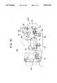
- FIG. 3 is an enlarged fragmentary sectional view of a portion of another embodiment of the present invention.
- FIG. 4 is a perspective view of the embodiment shown in FIG. 3;
- FIG. 5 is a plan view illustrating the arrangement of various units incorporated in the embodiment of FIG. 4;
- FIG. 6 is a sectional view of a sample table and a reagent table taken along the axis of rotation;
- FIG. 7 is an exploded perspective view of the mechanism shown in FIG. 6;
- FIG. 8 is a perspective view of a pipetting mechanism
- FIG. 9 is a perspective view of a washing unit
- FIG. 10 is a schematic illustration of an optical system in a fluorescent photometer
- FIG. 11 is a sectional view of a reaction table taken along the axis thereof;
- FIG. 12 is a schematic illustration of liquid lines
- FIG. 13 is a flow chart explanatory of the analyzing process executed with the automatic analyzing system of the present invention.
- a first embodiment of the analyzing system in accordance with the present invention has a shaft 313 which carries a sample table 315 having a plurality of sample vessel pockets 314 which arearranged at a predetermined pitch or interval in the circumferential direction.
- the sample table 315 is rotatable with the shaft 313 about the axis of the shaft 313.
- a reagent table 310 having a diameter greater than that of the sample table 315 is fixed to a portion of the shaft 313 which is axially spaced downward from the sample table 315.
- the reagent table 310 is also rotatable with the shaft 313 about the axis of the shaft 313.
- the reagent table 310 supports a plurality of reagent vessels 311. In the embodiment shown in FIG.
- the reagent table 310 has a plurality of reagent pack pockets 312a which are arranged radially around the shaft 313. Each of these reagent pack pockets 312a receives a reagent pack 312 which includes three reagent vessels 311 charged with different reagents. Thus, a plurality of reagent packs 312 are arranged on the reagent table 310 radially around the shaft 313.
- the system further has a reaction table302 which is fixed to a shaft 303 such that the reaction table 310 is set in a side-by-side relation to the sample table 315 and the reagent table 310 on the shaft 313.
- the reaction table 302 is rotatable with the shaft 303 about the axis of this shaft.
- the reaction table 302 has a plurality of reaction vessel pockets 301 which are arranged in the circumferential direction.
- the shaft 303 carrying the reaction table 302 and the shaft 313carrying the sample table 315 and the reagent table 310 are driven by a driving system which will be described later in connection with another embodiment.
- the system is also provided with a vibratory driving device (not shown) capable of vibrating the reaction table 302 at a high velocity and with a very small amplitude.
- This vibratory driving device also will be describedin connection with another embodiment.
- the reaction vessel pockets 301 receive reaction vessels 301'.
- a thermostat cell 305 and a cold preserving cell 316 are provided as will be explained later.
- a single pipetting device 317 is disposed between the reaction table 302 and the reagent table 310.
- the pipetting device 317 has an arm 300 which is pivotable about the axis of a shaft 304 and is movable up and down along the axis of the shaft 304.
- the arm 300 is provided at its free end with a probe 318 having a liquid removing and discharging function. Namely, the probe 318 is capable of removing samples from the sample vessels 314' in the sample vessel pockets 314 of the sample table 315 and discharging the same into the reaction vessels 301' in the reaction vesselpockets 301 of the reaction table 302.
- the probe 318 is also capable of sucking reagents from the reagent vessels 311 in the reagent vessel pockets 312a of the reagent table 310 and discharging the same into the reaction vessels 301' in the reaction vessel pockets 301 of the reaction table 302.
- the pivotal support of the arm 300 enables the samples and the reagents to be transferred from the sample table 315 and the reagent table 310 to the reaction table 302 and the axial movement of the arm in the vertical direction enables the probe 318 to be moved to andfrom positions in the vicinity of the respective tables.
- the reaction table 302 carries a fluorescent photometer 325 which is well known to those skilled in the art.
- the arrangement is such that a light emitted from a light source 326 is applied to successive reaction vessels 301' and the light transmitted through the reaction vessels is measured bythe fluorescent photometer 325 or the light absorption photometer, thereby analyzing a sample such as antigen.
- the reaction table 302 also carries a washing device 309 which will be described later in connection with another embodiment.
- the washing device 309 is movable towards and away from the reaction table 302 so as to wash the reaction vessels 301'.
- a second washing device 319 is provided betweenthe reaction table 302 and the sample table 310 and is capable of washing the probe 318.
- the reagent is selected in accordance with the purpose of the analysis. For instance, when immune reaction is to be examined, reagents composed of fine solids coated with antibody, a reaction-stopping reagent and a reagent for color reaction areused as the reagent. The reagent is changed in the reagent vessels 311 in the reagent pack pockets 312a of the reagent table 310.
- the solid reagent may be of any form of solid which is constructed to reactwith the material to be measured, such as the vessel itself with the inner wall thereof coated with antibody, glass bead coated with antibody or fineparticles coated with antibody.
- a plurality of packs 312 each including three reagent vessels 311 are arranged radially so that each pack can supply three different reagents.
- two types ofreagent namely, a reagent composed of fine solid particles coated with antibody and a reagent for color reaction, are used in the analysis.
- the arm 300 of the pipetting device 317 is swung so as to enable the probe 318 to remove a predetermined quantity of the sample from the sample vessel 314' in one of the sample vessel pockets 314 and to deliver the thus sucked sample into one of the reaction vessels 301' on the reaction table 302.
- the probe 318 of the pipetting device 317 is washed by the washing device 319 so as to prevent any contamination which may otherwise be caused by a carry-over of the sample.
- the reaction table 302 is vibrated for several seconds by the vibratory driving device and, thereafter, the reaction table 302 is rotated through an angle which corresponds to the pitch of arrangement of the reaction vessels.
- sample table 315 is also rotated to bring the next sample vessel to the pipetting position. This operation is repeated so that samples are successively transferred from the sample vessels 314' containing samples to be examined to a plurality of reaction vessels 301' on the reaction table 302.
- the pipetting device 317 operates in a manner similar to thatdescribed above, so as to transfer reagents from the reagent vessels 311 tothe successive reaction vessels 301' which have already been charged with the samples. More specifically, the transfer of the reagents is conducted from each reagent pack 312 such that the first reagent is removed and delivered first, the probe 318 is washed by the washing device 319 and then the second reagent is transferred. After the supply of the reagents, the reaction table 301 is vigorously vibrated again by the vibratory driving device so that the sample and the reagents are strongly stirred and mixed with each other.
- the antigen and the solid particles coated with antibody are caused to contact with each other with the result that the reactable portion of the antibody is bonded to the antigen.
- the solid reagents are washed away by the washing device 309 so that an unreacted portion of the mixture is discharged from the reaction vessels 301'.
- a framework which is an enzyme reaction liquid is added to the contents of the reaction vessels 301' by means of the pipetting device 317 thereby to cause coloring reaction.
- the probe 318 is washed by the washing device 319.
- a light emitted from the light source 326 is caused to pass through the reaction vessels 301' and the transmitted light is measured by the fluorescent photo-meter, whereby the presence or absence of the antigen in each reaction vessel and the concentration thereof are analyzed.
- FIG. 2 is a time chart of the analyzing process.
- the axis t represents time.
- the hatched portion of a bar 320 represents the time required for the pipetting of the sample, while the blank portion of this bar 320 showsthe time prepared for the washing of reaction vessels 301' by the washing device 309. No washing is conducted in this pipetting operation.
- the bar 321 shows the time required for the pipetting of the reagent.
- bars 321, 323 and 324 show, respectively, the time lengths required for the steps of washing, coloring reaction reagent pipetting and photometry.
- FIGS. 3 to 13 Another embodiment of the automatic analyzing system of the present invention will be described with reference to FIGS. 3 to 13. This embodiment is aimed at minimizing the size of the reagent cold preservation cell and providing a structure which is simple but yet capable of effectively shielding the interior of the reagent cold preservation cell from the ambient air.
- FIG. 4 is a perspective view of the whole of this embodiment, while FIG. 5 is an illustration showing various units incorporated in this embodiment.
- the automatic analyzing system shown in FIG. 4 has a base 1 which carries all the major units and wirings of the system. These units and wirings arecovered by an intermediate cover 2 which is assembled with a frame 3.
- the system is enclosed by a left side cover 4, a right side cover and a rear cover.
- a printer 10, a CRT 11, a keyboard 12 and a bar code reader 13 are arranged on a right slanted surface of the frame 3 so as to be operated easily.
- the frame 3 has a large opening which is on the left side of the above-mentioned slanted surface as viewed in FIG. 4. This opening is normally closed by an upper cover 14 which is swingable between an open position and a close position.
- the upper cover 14 is made of a light-transmitting material so as to enable the user to observe the interior of the system.
- a pipetting device 15 and a sample table 16 are disposed under the above-mentioned intermediate cover 2 which is positioned below the upper cover 14.
- a reagent table 17 is disposed immediately below the sample table 16 coaxially therewith. The reagent table 17 is hidden behind the sample table 16 and, therefore, is invisible.
- a reaction table 18 on which the sample and the reagent are made to react is disposed at the left side of the stack of the sample table 16 and the reagent table 17.
- a washing device 20 capable of separating the reaction liquid from the solid reagents is secured to the underside of a slanted wall inside the upper cover 14 at a position adjacent to the reaction table 18.
- a peristaltic pump 21 is disposed behind the washing device 20 and capable of sucking the reaction liquid through the washing device 20.
- a washing syringe pump 22 capable of supplying a washing liquid for washing the solid reagents and a pipetting syringe pump 23 for metering the samples and the reagents to be pipetted by the pipetting device 15 are provided onthe inner side of the left side cover 4.
- a base plate unit 24 incorporatinga microcomputer is disposed inside the right side cover, while a compressorunit 25 is disposed inside the rear cover.
- a plurality of reagent vessels 35 on the reagent table 17 are housed in a reagent cold preservation cell 26 which is cooled by chilled water to a temperature which is low enough to prevent degradation of the reagents.
- the cold preservation cell 26 is connected to a source of the chilled water. Any suitable cooling methods other that the cooling by chilled water, e.g., cooling by Peltier effect, may be used for maintaining the reagents at such a low temperature.
- the pipetting syringe pump 23 is connected by piping (not shown) to a probe tube of the pipetting device 15.
- a pump 63 disposed at a left rear portionof the system as viewed in FIG. 5 is capable of sucking water from a water tank 70 (see FIG. 12) and delivering the water for filling the pipetting syringe pump 23 and the pipetting device 15 up to the probe and for enabling the pipetting probe to conduct pipetting of the sample and the reagent, as well as for washing the probe.
- the washing liquid in a washing liquid bottle 69 is used for washing the solid reagents after the discharge of the liquid from the reaction vessels36.
- a fluorescent photometer 49 is disposed under the reaction table 18 so that the reaction vessels provided on the reaction table successively moveacross the path of light.
- awashing tank 64 for washing the probe of the pipetting device 15 and a common reagent cell 65 which is used commonly for fluorescent photometry of different analysis items.
- the washing tank 64 and the common reagent cell 65 are disposed on a path of pivotal movement of the probe.
- the reagent table 17 is housed in a reagent cold preserving cell 26 so as to be maintained at a temperature which is low enough to prevent degradation of reagents.
- a floppy disk drive (FDD) 66 is provided on the right lower side of the reagent cold preserving cell 26 and is capable of storing information concerning the conditions of analysis to be performed by the system. The construction of each unit of this system will be described hereunder.
- FIG. 6 shows in section the sample table 16, the reagent table 17 and the reagent cold preserving cell 26, while FIG. 7 shows these parts in exploded perspective view.
- FIG. 3 is an enlarged sectional view of a portion of the arrangement shown in FIG. 6.
- the sample table 16 is disposed above the reagent table 17 coaxially therewith. These tables 16 and 17 are secured to a common drive shaft 27 through brackets 28 and 29, respectively.
- the drive shaft 27 is rotatably supported by a bearing 30 and is provided at its lower end with a gear 31 which engages with a pinion 33 fixed to the output shaft of a pulse motor 32.
- the sample table 16 carries a plurality of sample vessels 34 which arearranged along the outer peripheral edge of the table 16.
- a plurality of reagent vessels 35 are arranged along the outer peripheral edge of the reagent table 17.
- the reagent table is housed together with the reagent vessels 35 in the reagent cold preserving cell 26.
- the cold preserving cell 26 has an annular form and is arranged such that the portion of the reagent table 17 near the outer peripheral edge of the table 17 moves in the cold preserving cell 26 as the reagent table 17 is rotationally driven by the drive shaft 27 which is rotated by the power ofthe pulse motor 32.
- the reagent cold preserving cell 26 has lower, upper, radially inner and outer heat-insulating walls 261, 262, 263 and 263a which cooperate together to define an annular space.
- the reagent cold preserving cell 26 is also provided with a cold preserving cell cover 264 which closes the abovementioned annular space.
- a disk section 265 (see FIG. 7) including the sample table 16 and the reagent table 17 are securedto the drive shaft 27 together with the bearing 30.
- the cold preserving cell cover 264 is provided with a probe insertion port 267 for enabling the probe of the pipetting device 15 to be inserted into the cell 26.
- a seal means is provided between the cold preserving cell 26 and the reagent table 17.
- the detail of the seal will be describedwith specific reference to FIG. 3.
- a pair of annular grooves 2631 are provided in the upper end of the inner wall 263 of the reagent cold preserving cell 26.
- a pair of annular ribs 171 formed on a portion of the lower surface of the reagent table 17 opposing these grooves 2631 are received in these annular grooves so as to form a labyrinth seal 268a.
- a similar labyrinth seal 172a is formed also between the upper surface of the reagent table 17 and the reagent cold preserving cell cover 264.
- the latter labyrinth seal 172a includes a pair of annular ribs 2641 formed on the lower surface of the reagent cold preserving cell cover 264 while mating annular grooves 172 are formed in the upper surfaceof the reagent table 17 facing the reagent cold preserving cell cover 264.
- These ribs 171 and 2641 and the corresponding grooves 2631 and 172 are slightly spaced apart from each other so that they do not directly contacteach other.
- the labyrinth type seals 268a and 172a provided between the rotatable reagent table 17 and the stationary reagent cold preserving cell26 provides the following effect: Namely, when the analyzing system is started, chilled air flows through the minute gaps between the grooves 2631 and 172 and the corresponding ribs 171 and 2641 so that the chilled air forms dew due to difference in the temperature between the chilled airand the ambient air. The dew forms droplets which are accumulated in the grooves 2631 and 172 and grow to such an extent as to clog the minute gapsbetween the grooves and the ribs, thus preventing further leakage of the chilled air. The dewing is ceased accordingly.
- a detection plate 173 is secured to the lower side of a part of the reagenttable 17 which is radially inwardly of the seal 268a. This detection plate 173 cooperates with a photo-interrupter 47 to detect a state of interruption of a light so that the rotation of the reagent table 17 is controlled by a controller (not shown) in accordance with the result of the detection.
- the multiplicity of sample vessels 34 which are arranged in two rows alongthe outer peripheral edge of the sample table 16, and the multiplicity of reagent vessels 35 arranged on the reagent table 17 are arranged around the axis of the common drive shaft 27 such that the vessels 34 and 35 do not radially overlap each other.
- the pipetting device 15 has onlyone probe 1513 (see FIG. 8), the above-described arrangement of the sample vessels and the reagent vessels enables the single probe of the pipetting device 15 to suck the samples and the reagents on the path of movement thereof and transfer them to the reaction vessels on the reaction table 18.
- reaction table 18 The construction of the reaction table 18 will be described in detail with reference to FIG. 11.
- the reaction liquid in the reaction vessels 36 arranged along the outer periphery of the reaction table 18 is held at a constant temperature, for example, 37° C. within an annular air thermostat tank 37 to assure a stable reaction.
- the thermostat tank 37 is provided with an air circulation chamber 38 through which heated air is circulated so as to heat the reaction liquid up to 37° C. in a short time.
- the air circulation chamber 38 has a heater 381 for heating the air to maintain the air temperature at 37° C., a temperature sensor 382 and a blower 383.
- the reaction table 18 is fixed to the upper end of a drive shaft 40 which is rotatably supported by a driving base 39.
- the drive shaft 40 is provided at its lower end with a pulley 41 which is drivingly connected through a timing belt 44 to a pulley 43 on a pulse motor 42.
- Theangle of rotation of the reaction table 18 is detectable by means of a detection plate 45 which is formed integrally with the reaction table 18 and which cooperates with a photo-interrupter 46 to detect the state of interruption of a light.
- FIG. 8 shows the construction of the pipetting device 15.
- the pipetting device 15 has a pipetting arm 1511 which is fixed at its one end to a drive shaft 1512 while the other end carries a single probe 1513 secured thereto.
- the drive shaft 1512 is supported by a ball spline bearing 1514 so as to be movable up and down and is rotatably supported by a frame 1515.
- the vertical movement of the drive shaft 1512 is effected by the power of a pulse motor 1516 transmitted through a pinion 1517, a rack 1518and a vertically movable frame 1519.
- the rotation of the drive shaft 1512 is effected by another pulse motor 1520 the output of which is transmittedto the ball spline bearing 1514 through a pulley (not shown) on the lower side of the output shaft of this pulse motor 1520, a timing belt 1522 and a pulley 1523.
- the arrivals of the pipetting arm 1511 at the upper and lower ends of its stroke are detected by a combination of a detection plate (not shown) and a photo-interrupter (not shown), while the detection of angular position of the arm is conducted by a detection plate 1524 which cooperates with another photo-interrupter which is not shown.
- the vertical position and the rotational position of the pipetting arm are controlled by a controller which receives signals from these detection plates.
- the probe 1513 is rotatable to cover an area between the inner row of the sample vessels 34 arranged on the sample table 16 shown in FIG. 5 and the sample discharge port 48 through which the sample is discharged into the reactionvessels 36 arranged on the reaction table 18.
- the samples and the reagents supplied into the reaction vessels 36 by the pipetting device 15 are heated to the afore-mentioned constant temperaturewhich is 37° C. for example so as to react with each other.
- a washing operation is performed by a washing device 20 which is disposed adjacent to the reaction table 18 in order to wash the reaction liquid away from the reaction vessels 36.
- a washing device 20 which is disposed adjacent to the reaction table 18 in order to wash the reaction liquid away from the reaction vessels 36.
- FIG. 9 shows the details of the washing device 20.
- the washing device 20 has washing nozzles 2001 secured to a washing arm 2002.
- the washing arm 2002 is provided with a rack 2005 engaging with a pinion 2004 fixed to theoutput shaft of each of a pair of drive motors 2003 so that the washing arm2002 is movable back and forth by the force of the motor 2003.
- the forward/backward driving unit is secured to a vertically movable frame 2006 and is adapted to be moved up and down together with the frame 2006 by a drive shaft 2011 carried by a base 2010, and vertically movable by the a cooperation between a pinion 2008 on the output shaft of a pulse motor 2007 and a rack 2009.
- a membrane breaking mechanism 2012 is secured to the frame 2006.
- the membrane breaking mechanism 2012 has a membrane breaking bar 2013 which is movable vertically so as to break a membrane (not shown) closing the opening of each reaction vessel 36 for the purposeof preventing evaporation of the reaction liquid or for other purposes suchas prevention of jumping out of stirring balls or tablets charged in reaction vessels 36.
- the liquid phase is discharged by means of the washingnozzle 2001. Then, a reagent which enables the remaining solid phase to produce fluorescent luminance is delivered into the reaction vessels by means of the pipetting device 15. After the elapse of a predetermined time, the intensity of fluorescent luminance is measured by the fluorescent photometer 49.
- FIG. 10 illustrates the construction of the fluorescent photometer 49.
- the light emitted from a light source lamp 50 is condensed by the lens 51 and is contracted through a mask 52. Then, the light of the required excitation wavelength is picked up through a grating 53 in a spectrometer 605 of the excitation side of the photometer.
- the light of the excitation wavelength is reflected by a mirror 54 so as to impinge upon a troidal mirror 55 which collects the scattered light so as to focus the light on apredetermined portion in the reaction vessel 36.
- the light of fluorescent wavelength When the light of the excitation wavelength is applied to the reaction liquid in the reaction chamber, the light of fluorescent wavelength of an intensity proportional to the density of the reaction liquid is produced from the entire circumference of the liquid.
- the fluorescent photometer 49 used in the embodiment of the present invention is designed to detect the fluoroescentwavelength light which is perpendicular to the direction of the incidence of the excitation wavelength light.
- the detected fluorescent light is condensed through a lens 56 and is made to pass through a wavelength-selection filter and mask 57 so as to impinge upon a photo-multiplier tube 58, whereby an electric signal of a level proportional to the fluorescent light intensity is produced by the photo-multiplier tube 58.
- the level of dark current in the photo-multiplier tube 58 is measured by making use of a shutter 59.
- a light split by a half mirror 60 is received by a photo-diode 61.
- the output level of the source lamp 50 is monitored and controlled in accordance with the output from the photo-diode 61.
- FIG. 12 shows various liquid lines arranged in the embodiment shown in FIG.4. These lines are broadly classified into four systems.
- a first liquid line system extends from a water tank 70 containing ionized water or distilled water to the probe 1513 of the pipetting device 15 through the pump 63 for sucking the water from the tank 70 and then through the pipetting syringe pump 23.
- a second liquid line system includes a drain pipe from a washing tank 64 for washing the probe and for receiving liquiddischarged from the probe, as well as a drain pipe from an air purge tank 67 for discharging the washing liquid from the washing bottle 69 during air-purging of the washing device 20. These drain pipes are connected into a common pipe which leads to a drain tank 71.
- a third liquid line system includes lines through which a washing liquid is sucked from the washing bottle 69 by a washing syringe pump 22 and discharged to the reaction vessels 36 by means of the washing nozzle 2001 of the washing device 20.
- Afourth liquid line system includes lines for sucking up the reaction liquidfrom the reaction vessels 36 by the perista pump 21 through another washingnozzle 2001 of the washing device 20 and for discharging the sucked reaction liquid into a waste liquid bottle 7.
- symbols SV1 to SV7 show stop valves. The operation of this embodiment will be described hereinunder.
- Necessary analyzing conditions are input in a dialogue manner by means of the CRT 11 and the keyboard 12. Then, reagent vessels 35 are set on the reagent table 17 after reading the bar codes on the reagent vessels 35 by means of the bar code reader 13. A plurality of reagent vessels 35 are arranged on the reagent table 17 in accordance with the items of analytical measurement, as shown in FIG. 5. On the other hand, sample vessels 34 charged with the samples to be analyzed are set on the sample table 16. In addition, reaction vessels 36 for receiving the samples and the reagents are arranged over the entire circumference of the reaction table 18. The common reagent bottle 65 and the washing liquid bottle 69 are also set on predetermined portions of the analyzing system.
- the analyzing system is now ready to operate.
- an operation is commended for checking conditions such as the state of setting of the reaction vessel 36, the amount of the common reagent in the common reagent bottle 65 and the amount of washing liquid in the washing bottle 69.
- the pump 63 is operated to effect air-purge of the liquid line system.
- the checking operation is automatically performed as an initial routine for initializing the whole system. In case of any abnormality in the result ofthe check, an alarming buzzer goes off to inform the operator of the occurrence of the abnormality.
- the state of the abnormality is displayed on the CRT 11 and the data concerning the abnormality is printed out by the printer 10.
- the process proceeds to a next step when noabnormality is found through the checking operation.
- the analyzing cyclic operation is then started. The analyzing process will be described with reference to a flow chart shown in FIG. 13.
- Liquids extracted from living bodies such as a liquid containing antigen, blood serum, plasma and urin are usable as the samples.
- the reagents used in this system are those used ordinarily. In case of an analysis of immunereaction of fine virus, a solid reagent coated with antibody is suitably used.
- the sample vessels 34 are heated up to and maintained at the predetermined temperature in the reagent thermostat cell. The sample exhibits a large fluctuation in the viscosity between 1 and 8 cps at room temperature. The characteristics of the samples will be lost if the samples are heated to a to high temperature.
- a too low temperature of the samples will increase the viscosity to such an extent as to impair the accuracy of metering performed by the probe 1513 of the pipetting device 15. It is therefore necessary that the samples are heatedto and maintained at a temperature which is slightly lower than the normal temperature.
- the reagent vessels 35 are held in the reagent cold preserving cell 26 so as to be maintained at a predetermined temperature, e.g , 8° C., which is suitable for shelving the reagents stably for a long period.
- a predetermined quantity of the sample is sucked up from the sample vessel 34 on the sample table 16 by means of the probe 1513 of the pipetting device 15 and is transferred to and discharged into a designated reaction vessel 36 on the reaction table 18.
- theprobe 1513 of the pipetting device 15 is well washed in the washing tank 64to eliminate any contamination which may otherwise be caused by a carry-over of the sample.
- the reaction table 18 is vibrated for several seconds by the vibratory driving device which is composed of the pulse motor 42, the pulley 43, the timing belt 44, the pulley 44 and the drive shaft 40, thereby shaking and stirring the reaction liquid. Then, the reaction table 18 is rotated by an amount which corresponds to the pitch of arrangement of the reaction vessels.
- the sample table 16 is rotated to bring a succeeding sample vessel 34 to the sucking position. This operation is repeated until all the necessary reaction vessels 36 are charged with the samples. Then, a similar cyclic pipetting operation is executed to suck the reagents from the successive reagent vessels 35 and to discharge the same into the respective reaction vessels 36. When a plurality of types of reagents are used, the transfer of the first reagent is followed by the transfer of the second reagent. The reaction table 18 is thus rotated in an indexed manner so as to transfer the samples and reagents into the successive reaction vessels 36 on the reaction table 18. It will be seen that the construction of the analyzing system is simplified due to the use of the described pipetting system.
- Thedescribed mode of pipetting is not exclusive.
- the pipetting and the rotation of the reaction table 18 may be executed in such a manner that, after delivering a sample into a reaction vessel 36 bymeans of the pipetting mechanism 15, the probe of the pipetting mechanism is washed and then used for pipetting the reagent into the same reaction vessel 36 while the reaction table 18 is kept stationary.
- the reaction table 18 may be rotated intermittently after filling each reaction vessel both with the sample and the reagent.
- the first-mentioned mode of pipetting operation i.e., delivery of the reagent to successive reaction vessels 36 after charging of these reaction vessels with samples, is preferred.
- a reagent used is composed of a solid coated with antibody.
- Samples containing antigen such as virus are charged into the reaction vessels and the above-mentioned reagent composed of solid coated with antibody is added to the samples.
- the reaction table carrying the reaction vessels 36 is then vigorously vibrated by the vibratory driving device which includes the pulse motor 42controlled in accordance with a driving control signal, whereby the sample and the reagent in each reaction vessel are strongly stirred and blended.
- the antigen and the solid carrying the antibody contact witheach other so that the reactable portion of the antibody is boded to the antigen.
- the solid reagent is washed and unreacted liquid which causes noises in the high-sensitivity measurement is discharged by means of the nozzle of the washing device 20.
- the solid reagent is washed again by the washing liquid supplied from another nozzle of the washing device.
- the washing device 20 can be moved up and down as required. After washing the solid reagent, a framework which is an enzyme reaction liquid is addedto cause coloring reaction.
- the analyzing system described hereinbefore can also be used for ordinary antigen/antibody reaction, though a high-sensitivity measurement of immune reaction has been specifically mentioned.
- the ability of conducting the high-sensitivity measurement of immune reaction enables this system to be used for diagnosis of acquired immune deficiency (AIDS).
- the described system can perform a highly accurate measurement of antigen in the sample on the order of 10 -6 to 10 -13 Mol/l in terms of the antigen content.
- all the known biochemical analyzing systems could provide only a low levelof sensitivity, e.g., 10 -6 Mol/l or less.
- the analyzing system of the invention provides a sensitivity which is about 10 6 times as high as that of known analyzing systems.
- the operation of the portions of the apparatus around the reagent table 17 will be described in detail with reference to FIG. 3. Though the arrangement has already been described, the parts and components around the reagent table 17 will be described again for the purpose of facilitating the understanding of operation.
- the portion of the reagent table 17 carrying the reagent vessels 35 is housed in the reagent cold preserving cell 26. In order to allow the reagent table 26 to rotate relative to the reagent cold preserving cell 26 which is stationary, it isnecessary that minute gaps be left between the table 17 and the cell 26 at both sides of the table 17.
- the chilled air escapes from the reagent cold preserving cell 26 through these gaps and the chilled air leaking through these gaps tends to form dew upon contact with the ambient air due to difference in the temperature and humidity between itself and the ambient air.
- the dew progressively grows and forms a water pool, with the result that the chilled air is wastefully consumed.
- the compressor of the refrigeration system for cooling the air is required to have a large capacity and consumes much energy.
- the described embodiment employs seals 172a and 268a of the type described before with reference to FIG. 3.
- the chilled air escapes from the reagent cold preserving cell 26 through the labyrinth type seals 172a and 268a.
- the flow rate of the escaping chilled air is limited because of the labyrinth-type structure of the seal sothat a large sealing effect is obtained as compared with the straight gaps.
- the dew generated in the labyrinth type seals grows into dew droplets which then gather to fill the grooves of the labyrinth type seals.
- the gap between the groove 2631 and the rib 171 and the gap between the groove 172 and the rib 2641 is completely filled with the water so that the escape of the chilled air does not take place any more.
- the reagent table can smoothly rotate without substantial resistance while maintaining effective seal between itself and the reagent cold preserving cell.
- the automatic analyzing system of the present invention has a plurality of reagent packsarranged on the reagent table, each pack including a plurality of reagent vessels containing different reagents corresponding to different analytical measurement items. These packs are replaceable in accordance with a change in the analytical measurement item or items.
- the reagent table and the sample table are driven by a common drive systemand the samples and reagents are transferred to the reaction vessels by means of a single pipetting device. In consequence, the pipetting arrangement and the driving arrangement are remarkably simplified.
- the analyzing system of the present invention can be realized in the form of a compact desk-top type device.
- the analyzing system of the present invention is suitable for use in the caseswhere a multiplicity of types of reagent are employed for each analytical measurement item, as in the case of the current immune reaction measurement which generally use up to 5 types of reagents.
- the analyzing system of the present invention which is easy to operate, can be used in various types of biochemical analysis including clinical analysis.
- the labyrinth type seal provided between the rotatable reagent table and the stationary reagent cold preserving cell effectively prevents the chilled air from escaping from the reagent cold preserving cell without frictional resistance.
- This seal is highly reliable because of its simple construction and contributes to saving energy because the wasteful consumption of chilled air is minimized.
- liquid lines formed by flexible tubes are arranged in quite a complicated manner so that the tubes tend to be entangled with each other to allow stagnation of liquids in bent or recessing portion of these tubes, with the result that various kinds of bacteria are allowed to glow so as to clog these tubes.
- the analyzing system of the present invention because the liquid lines or channels in the system of the present invention can be formed of rigid or hard tubes such as hard vinylchloride tubes which can be arranged at suitable degrees of inclination so as to promote natural flow of the liquids.
Abstract
Description
Claims (3)
Applications Claiming Priority (4)
| Application Number | Priority Date | Filing Date | Title |
|---|---|---|---|
| JP62-293400 | 1987-11-20 | ||
| JP29340087A JPH01136068A (en) | 1987-11-20 | 1987-11-20 | Automatic analyzer |
| JP63210748A JP2585741B2 (en) | 1988-08-26 | 1988-08-26 | Automatic analyzer for measuring multiple items |
| JP63-210748 | 1988-08-26 |
Publications (1)
| Publication Number | Publication Date |
|---|---|
| US5051238A true US5051238A (en) | 1991-09-24 |
Family
ID=26518254
Family Applications (1)
| Application Number | Title | Priority Date | Filing Date |
|---|---|---|---|
| US07/272,345 Expired - Fee Related US5051238A (en) | 1987-11-20 | 1988-11-17 | Automatic analyzing system |
Country Status (2)
| Country | Link |
|---|---|
| US (1) | US5051238A (en) |
| DE (1) | DE3839080A1 (en) |
Cited By (106)
| Publication number | Priority date | Publication date | Assignee | Title |
|---|---|---|---|---|
| US5174162A (en) * | 1989-07-10 | 1992-12-29 | Hitachi, Ltd. | Pipetter, pipette tube, sample analyzing apparatus including them and method of mixing and pipetting liquids |
| US5207987A (en) * | 1990-05-21 | 1993-05-04 | Pb Diagnostic Systems Inc. | Temperature controlled chamber for diagnostic analyzer |
| US5244633A (en) * | 1992-05-22 | 1993-09-14 | Eastman Kodak Company | Analyzer incubator with plural independently driven rings supporting cuvettes |
| WO1993019928A1 (en) * | 1992-03-27 | 1993-10-14 | Abbott Laboratories | Plastic assay cuvette having low birefringence |
| WO1993020441A1 (en) * | 1992-03-27 | 1993-10-14 | Abbott Laboratories | Automated continuous and random access analytical system and components thereof |
| WO1993020440A1 (en) * | 1992-03-27 | 1993-10-14 | Abbott Laboratories | Automated continuous and random access analytical system and components thereof |
| WO1993020450A1 (en) * | 1992-03-27 | 1993-10-14 | Abbott Laboratories | Automated continuous and random access analytical system |
| US5270210A (en) * | 1992-07-16 | 1993-12-14 | Schiapparelli Biosystems, Inc. | Capacitive sensing system and wash/alignment station for a chemical analyzer |
| US5356525A (en) * | 1993-04-16 | 1994-10-18 | Beckman Instruments, Inc. | Sample handling system |
| US5424036A (en) * | 1992-04-24 | 1995-06-13 | Olympus Optical Co., Ltd. | Automatic analyzer |
| US5439646A (en) * | 1992-09-30 | 1995-08-08 | Shimadzu Corporation | Blood coagulation analyzer |
| US5443790A (en) * | 1991-07-26 | 1995-08-22 | Societe Francaise De Recherches Et D'investissements (Sfri) | Device for automatically analyzing samples |
| US5456882A (en) * | 1990-11-16 | 1995-10-10 | Societe Alcyon Analyzer S.A. | Reaction segment for an automatic sample analyzer |
| US5470534A (en) * | 1993-05-10 | 1995-11-28 | Hitachi, Ltd. | Analytical system useful in diagnosis of the condition of a disease |
| WO1996000397A1 (en) * | 1994-06-24 | 1996-01-04 | Pasteur Sanofi Diagnostics | Method and apparatus for automated chemical analysis with variable reagents |
| US5507410A (en) | 1992-03-27 | 1996-04-16 | Abbott Laboratories | Meia cartridge feeder |
| US5510082A (en) * | 1993-01-25 | 1996-04-23 | Fuji Photo Film Co., Ltd. | Chemical analysis film supplier |
| US5523056A (en) * | 1994-04-29 | 1996-06-04 | Johnson & Johnson Clinical Diagnostics, Inc. | Twin rotor incubator assembly |
| US5536471A (en) | 1992-03-27 | 1996-07-16 | Abbott Laboratories | Syringe with bubble flushing |
| US5540890A (en) | 1992-03-27 | 1996-07-30 | Abbott Laboratories | Capped-closure for a container |
| EP0732591A2 (en) * | 1995-03-17 | 1996-09-18 | Hitachi, Ltd. | Automatic analyzer with abnormal condition display |
| US5575978A (en) | 1992-03-27 | 1996-11-19 | Abbott Laboratories | Sample container segment assembly |
| US5578494A (en) | 1992-03-27 | 1996-11-26 | Abbott Laboratories | Cap actuator for opening and closing a container |
| US5580524A (en) * | 1990-09-18 | 1996-12-03 | Anagen Limited | Assay or reaction apparatus with agitating device |
| US5587129A (en) * | 1994-09-21 | 1996-12-24 | Toa Medical Electronics Co., Ltd. | Apparatus for automatically analyzing specimen |
| US5595707A (en) * | 1990-03-02 | 1997-01-21 | Ventana Medical Systems, Inc. | Automated biological reaction apparatus |
| US5597733A (en) * | 1988-07-25 | 1997-01-28 | Precision Systems, Inc. | Automatic multiple-sample multiple-reagent dispensing method in chemical analyzer |
| US5599501A (en) * | 1994-11-10 | 1997-02-04 | Ciba Corning Diagnostics Corp. | Incubation chamber |
| US5605665A (en) | 1992-03-27 | 1997-02-25 | Abbott Laboratories | Reaction vessel |
| US5610069A (en) | 1992-03-27 | 1997-03-11 | Abbott Laboratories | Apparatus and method for washing clinical apparatus |
| US5609822A (en) * | 1995-07-07 | 1997-03-11 | Ciba Corning Diagnostics Corp. | Reagent handling system and reagent pack for use therein |
| US5622675A (en) * | 1993-04-16 | 1997-04-22 | Beckman Instruments, Inc. | Sample segment |
| US5627522A (en) | 1992-03-27 | 1997-05-06 | Abbott Laboratories | Automated liquid level sensing system |
| US5635364A (en) | 1992-03-27 | 1997-06-03 | Abbott Laboratories | Assay verification control for an automated analytical system |
| US5637275A (en) * | 1991-03-04 | 1997-06-10 | Chiron Diagnostics Corporation | Automated analyzer with reagent agitating device |
| US5646049A (en) | 1992-03-27 | 1997-07-08 | Abbott Laboratories | Scheduling operation of an automated analytical system |
| US5670114A (en) * | 1995-03-08 | 1997-09-23 | Hitachi, Ltd. | Apparatus of handling reagent for suppressing decrease in effect of reagent |
| US5679309A (en) * | 1995-12-14 | 1997-10-21 | Beckman Instruments, Inc. | Automated random access analyzer |
| US5719059A (en) * | 1995-07-11 | 1998-02-17 | Hitachi, Ltd. | Reagent management method and apparatus therefor |
| US5730938A (en) * | 1995-08-09 | 1998-03-24 | Bio-Chem Laboratory Systems, Inc. | Chemistry analyzer |
| US5750074A (en) * | 1995-01-23 | 1998-05-12 | Beckman Instruments, Inc. | Reagent segment |
| US5757659A (en) * | 1995-03-27 | 1998-05-26 | Ngk Insulators, Ltd. | Automatic analysis system |
| US5807523A (en) * | 1996-07-03 | 1998-09-15 | Beckman Instruments, Inc. | Automatic chemistry analyzer |
| US5882594A (en) * | 1996-06-14 | 1999-03-16 | Tosoh Corporation | Device and method for automatic sample pretreatment |
| US5885530A (en) * | 1996-06-28 | 1999-03-23 | Dpc Cirrus, Inc. | Automated immunoassay analyzer |
| US5960160A (en) | 1992-03-27 | 1999-09-28 | Abbott Laboratories | Liquid heater assembly with a pair temperature controlled electric heating elements and a coiled tube therebetween |
| US6066300A (en) * | 1995-07-07 | 2000-05-23 | Bayer Corporation | Reagent handling system and configurable vial carrier for use therein |
| US6190617B1 (en) | 1992-03-27 | 2001-02-20 | Abbott Laboratories | Sample container segment assembly |
| US6293750B1 (en) | 1998-07-14 | 2001-09-25 | Bayer Corporation | Robotics for transporting containers and objects within an automated analytical instrument and service tool for servicing robotics |
| US6319718B1 (en) * | 1998-07-27 | 2001-11-20 | Hitachi, Ltd. | Handling method of body fluid sample and analysis apparatus using the same |
| US20030017613A1 (en) * | 2001-07-13 | 2003-01-23 | Jakubowicz Raymond Francis | Tandem incubator for clinical analyzer |
| US20030045003A1 (en) * | 2001-07-20 | 2003-03-06 | Smith Jack V. | Method for detection of the adulterant urine luckTM in urine using liquid chemistry, dry chemistry test pads, and lateral flow |
| US20030147778A1 (en) * | 2002-02-06 | 2003-08-07 | Katsuaki Takahashi | Automatic analyzing apparatus |
| US6605213B1 (en) | 1998-05-01 | 2003-08-12 | Gen-Probe Incorporated | Method and apparatus for performing a magnetic separation purification procedure on a sample solution |
| US6709634B1 (en) * | 1999-05-11 | 2004-03-23 | Sysmex Corporation | Automatic analytical instrument |
| US20040105783A1 (en) * | 2002-07-10 | 2004-06-03 | Isao Yamazaki | Automatic analyzer |
| US20040219062A1 (en) * | 2003-04-30 | 2004-11-04 | Joseph Platano | Method and apparatus for sample preparation in an automated discrete fluid sample analyzer |
| US20040258565A1 (en) * | 2003-06-23 | 2004-12-23 | Shigenori Watari | Automatic analyzer |
| US6846455B1 (en) * | 2001-01-26 | 2005-01-25 | Ta Instruments-Waters, Llc | Automatic sampling device |
| US20050047964A1 (en) * | 2003-07-25 | 2005-03-03 | Masaharu Nishida | Automatic analyzer |
| EP1524526A1 (en) * | 2003-10-17 | 2005-04-20 | Hitachi High-Technologies Corporation | Reagent cassette and automatic analyzer using the same |
| US20060062692A1 (en) * | 2004-09-17 | 2006-03-23 | Hitoshi Tokieda | Automatic analyzer |
| US20060085140A1 (en) * | 2002-12-20 | 2006-04-20 | Gordon Feingold | Information notification sample processing system and methods of biological slide processing |
| US20070104614A1 (en) * | 2005-11-10 | 2007-05-10 | Shenzhen Mindray Bio-Medical Electronics Co., Ltd. | Automatic chemistry analyzer and analyzing method |
| US7250303B2 (en) | 2001-07-20 | 2007-07-31 | Ortho-Clinical Diagnostics, Inc. | Chemistry system for a clinical analyzer |
| US7270785B1 (en) | 2001-11-02 | 2007-09-18 | Ventana Medical Systems, Inc. | Automated molecular pathology apparatus having fixed slide platforms |
| US7303725B2 (en) | 2002-04-15 | 2007-12-04 | Ventana Medical Systems, Inc. | Automated high volume slide staining system |
| US7378055B2 (en) | 2002-04-26 | 2008-05-27 | Ventana Medical Systems, Inc. | Automated molecular pathology apparatus having fixed slide platforms |
| US7468161B2 (en) | 2002-04-15 | 2008-12-23 | Ventana Medical Systems, Inc. | Automated high volume slide processing system |
| US7547516B2 (en) | 2005-03-10 | 2009-06-16 | Gen-Probe Incorporated | Method for reducing the presence of amplification inhibitors in a reaction receptacle |
| WO2008090551A3 (en) * | 2007-01-23 | 2010-02-25 | Association For Public Health Services | Liquid testing assembly |
| WO2010057858A1 (en) * | 2008-11-18 | 2010-05-27 | Diasys Technologies S.A.R.L. | Automated analysis device with a rotating carousel for different liquid containers |
| US20110097240A1 (en) * | 2008-06-12 | 2011-04-28 | Hitachi High-Technologies Corporation | Analyzer using magnetic particles |
| CN1975432B (en) * | 2005-11-28 | 2011-05-18 | 沈阳东软医疗系统有限公司 | Sampling and stirring integrated device for full-automatic biochemical analyser |
| CN102192995A (en) * | 2010-03-11 | 2011-09-21 | 希森美康株式会社 | Sample analyzer and reagent management method |
| CN102221603A (en) * | 2010-04-14 | 2011-10-19 | 深圳迈瑞生物医疗电子股份有限公司 | Reagent bottle logical combination forming method and system as well as biochemistry analyzer |
| CN102221604A (en) * | 2010-04-14 | 2011-10-19 | 深圳迈瑞生物医疗电子股份有限公司 | Sample tray of biochemical analyzer |
| CN102221622A (en) * | 2010-03-18 | 2011-10-19 | 希森美康株式会社 | Sample analyzer |
| US8192992B2 (en) | 1998-05-01 | 2012-06-05 | Gen-Probe Incorporated | System and method for incubating the contents of a reaction receptacle |
| CN102985830A (en) * | 2010-07-09 | 2013-03-20 | 株式会社日立高新技术 | Automatic analyzer |
| CN103048479A (en) * | 2012-12-13 | 2013-04-17 | 江阴泽成生物技术有限公司 | Reagent sample system used for full-automatic chemiluminescence analyzer |
| US20130273524A1 (en) * | 2012-04-17 | 2013-10-17 | Joel R. L. Ehrenkranz | Device for performing a blood, cell, and/or pathogen count and methods for use thereof |
| US8718948B2 (en) | 2011-02-24 | 2014-05-06 | Gen-Probe Incorporated | Systems and methods for distinguishing optical signals of different modulation frequencies in an optical signal detector |
| CN103775513A (en) * | 2014-01-27 | 2014-05-07 | 南通苏通分离工程科技有限公司 | Shock-absorption support arm capable of raising and reducing temperature |
| US20150037211A1 (en) * | 2012-04-17 | 2015-02-05 | Shenzhen Mindray Bio-Medical Electronics Co., Ltd. | Automatic analyzers and reagent wheels thereof |
| US9046507B2 (en) | 2010-07-29 | 2015-06-02 | Gen-Probe Incorporated | Method, system and apparatus for incorporating capacitive proximity sensing in an automated fluid transfer procedure |
| CN104849483A (en) * | 2015-05-22 | 2015-08-19 | 上海裕隆生物科技有限公司 | Lifting system for washing fully-automatic reaction apparatus |
| CN104871000A (en) * | 2012-11-27 | 2015-08-26 | 株式会社Lg生命科学 | Automatic in vitro diagnostic apparatus including inclined rotating stirrer |
| US9134332B2 (en) | 2011-07-13 | 2015-09-15 | Roche Diagnostics Operations, Inc. | Instrument and process for the automated processing of liquid samples |
| US20160033487A1 (en) * | 2013-04-16 | 2016-02-04 | Shenzhen Mindray Bio-Medical Electronics Co., Ltd. | Dispensing device, immunoassay analyzer and method thereof |
| US9335338B2 (en) | 2013-03-15 | 2016-05-10 | Toshiba Medical Systems Corporation | Automated diagnostic analyzers having rear accessible track systems and related methods |
| US9400285B2 (en) | 2013-03-15 | 2016-07-26 | Abbot Laboratories | Automated diagnostic analyzers having vertically arranged carousels and related methods |
| CN106018784A (en) * | 2016-07-05 | 2016-10-12 | 深圳普门科技有限公司 | Small electrochemical luminescence immunoassay analyzer and analysis method thereof |
| CN106770913A (en) * | 2016-12-09 | 2017-05-31 | 中储粮成都粮食储藏科学研究所 | A kind of fatty acid value automatic tester |
| US20170219615A1 (en) * | 2016-01-31 | 2017-08-03 | Arkray, Inc. | Analysis tool and analysis device |
| US20180080950A1 (en) * | 2016-09-16 | 2018-03-22 | Toshiba Medical Systems Corporation | Automatic analyzing apparatus |
| US20180137398A1 (en) * | 2007-11-13 | 2018-05-17 | Steve Rettew | Modular chemistry analyzer |
| US10001497B2 (en) | 2013-03-15 | 2018-06-19 | Abbott Laboratories | Diagnostic analyzers with pretreatment carousels and related methods |
| US10184862B2 (en) | 2008-11-12 | 2019-01-22 | Ventana Medical Systems, Inc. | Methods and apparatuses for heating slides carrying specimens |
| KR20190016483A (en) * | 2017-06-21 | 2019-02-18 | 푸지옌 커룽더 인바이런먼트 테크놀러지 컴퍼니 리미티드 | Water quality analyzer and water quality analysis method |
| US10375901B2 (en) | 2014-12-09 | 2019-08-13 | Mtd Products Inc | Blower/vacuum |
| US10794805B2 (en) | 2013-12-13 | 2020-10-06 | Ventana Medical Systems, Inc. | Automated histological processing of biological specimens and associated technology |
| CN113030462A (en) * | 2021-05-27 | 2021-06-25 | 山东康华生物医疗科技股份有限公司 | Full-automatic magnetic particle coating instrument |
| US11249095B2 (en) | 2002-04-15 | 2022-02-15 | Ventana Medical Systems, Inc. | Automated high volume slide processing system |
| CN115047204A (en) * | 2022-05-30 | 2022-09-13 | 山东博科诊断科技有限公司 | Chemiluminescence immunoassay appearance |
| US11913966B2 (en) | 2018-02-28 | 2024-02-27 | Hitachi High-Tech Corporation | Automated analysis device |
Families Citing this family (12)
| Publication number | Priority date | Publication date | Assignee | Title |
|---|---|---|---|---|
| JPH0640100B2 (en) * | 1987-11-27 | 1994-05-25 | 株式会社日立製作所 | Automatic analyzer sample dispensing method |
| US5104808A (en) * | 1988-08-26 | 1992-04-14 | Laska Paul F | Method and apparatus for effecting a plurality of assays on a plurality of samples in an automatic analytical device |
| DE3921393A1 (en) * | 1989-06-29 | 1991-01-10 | Lre Relais & Elektronik Gmbh | Appts. for automatic photometric analysis of e.g. blood - contains liq. specimen and reagent transfer devices and cuvette transport mechanism |
| DE3923833C2 (en) * | 1989-07-19 | 1998-07-02 | Boehringer Mannheim Gmbh | Analyzer for heterogeneous immunological tests |
| FR2654836B1 (en) * | 1989-11-17 | 1994-01-28 | Biotrol Sa Laboratoires | APPARATUS FOR AUTOMATICALLY PERFORMING MULTIPLE SUCCESSIVE IMMUNODAYS OF AT LEAST ONE BIOLOGICAL SUBSTANCE IN A PLURALITY OF BIOLOGICAL SAMPLES, PROCESS AND REAGENT USING THE SAME. |
| IE78906B1 (en) * | 1989-12-01 | 1998-03-11 | Akzo Nv | Sample handling system for an optical monitoring system |
| JPH0448267A (en) * | 1990-06-15 | 1992-02-18 | Hitachi Ltd | Automatic analysis apparatus |
| WO1992020778A1 (en) * | 1991-05-24 | 1992-11-26 | Kindconi Pty Limited | Biochemical reaction control |
| DE4121089A1 (en) * | 1991-06-26 | 1993-01-07 | Boehringer Mannheim Gmbh | ANALYSIS SYSTEM FOR THE AUTOMATIC ANALYSIS OF BODY LIQUIDS |
| DE4313807C2 (en) * | 1992-04-28 | 1995-03-09 | Olympus Optical Co | Reagent container system for the immunological analysis of a sample in an automatic analyzer |
| US5360597A (en) * | 1993-03-22 | 1994-11-01 | Eastman Kodak Company | Ribbed mechanism for mixing sample by vibration |
| DE69515565T2 (en) * | 1994-07-15 | 2000-11-02 | Dade Chemistry Systems Inc | Analyzer |
Citations (19)
| Publication number | Priority date | Publication date | Assignee | Title |
|---|---|---|---|---|
| US2946609A (en) * | 1958-04-08 | 1960-07-26 | Orenda Engines Ltd | Labyrinth seal |
| DE2025678A1 (en) * | 1969-07-17 | 1971-02-04 | American Optical Corp , Southbndge, Mass (V St A ) | Incubator and process turntable for a chemical analyzer for microsamples |
| JPS5070085A (en) * | 1973-10-24 | 1975-06-11 | ||
| DE3015051A1 (en) * | 1979-04-19 | 1980-10-23 | Olympus Optical Co | METHOD FOR DELIVERING SAMPLES AND REAGENTS IN REACTION TUBES |
| US4234538A (en) * | 1977-10-28 | 1980-11-18 | Coulter Electronics, Inc. | Apparatus for monitoring chemical reactions and employing moving photometer means |
| EP0041378A1 (en) * | 1980-05-30 | 1981-12-09 | Hitachi, Ltd. | Automatic analytical instrument |
| DE3102774A1 (en) * | 1980-01-28 | 1981-12-17 | Coulter Electronics Ltd., Luton, Bedfordshire | DEVICE FOR MULTIPLE TRANSFER OF LIQUID |
| EP0052006A1 (en) * | 1980-11-10 | 1982-05-19 | Hitachi, Ltd. | Automatic chemical analyzer |
| EP0074102A1 (en) * | 1981-09-04 | 1983-03-16 | Hitachi, Ltd. | Chemical analyzer equipped with reagent cold-storage chamber |
| DE3318573A1 (en) * | 1982-05-26 | 1984-01-05 | Orion-yhtymä Oy, 00101 Helsinki | ANALYZER |
| JPS62217163A (en) * | 1986-03-19 | 1987-09-24 | Nippon Tectron Co Ltd | Automatic analyzing instrument |
| US4774055A (en) * | 1985-06-26 | 1988-09-27 | Japan Tectron Instruments Corporation | Automatic analysis apparatus |
| US4778763A (en) * | 1985-04-19 | 1988-10-18 | Hitachi, Ltd. | Analytical method and apparatus for determining fluorescence or phosphorescence |
| DE3838361A1 (en) * | 1987-11-12 | 1989-05-24 | Hitachi Ltd | Analysis device for the agitation of a reaction solution and reaction container for use in the device |
| US4849177A (en) * | 1987-05-08 | 1989-07-18 | Abbott Laboratories | Reagent pack and carousel |
| US4871683A (en) * | 1985-04-18 | 1989-10-03 | Beckman Instruments, Inc. | Apparatus and method using a new reaction capsule |
| US4906433A (en) * | 1986-06-24 | 1990-03-06 | Kabushiki Kaisha Toshiba | Automatic chemical analyzer |
| US4908320A (en) * | 1986-07-11 | 1990-03-13 | Beckman Instruments, Inc. | Analyzer operating method |
| US4933147A (en) * | 1985-07-15 | 1990-06-12 | Abbott Laboratories | Unitized reagent containment system for clinical analyzer |
-
1988
- 1988-11-17 US US07/272,345 patent/US5051238A/en not_active Expired - Fee Related
- 1988-11-18 DE DE3839080A patent/DE3839080A1/en not_active Withdrawn
Patent Citations (19)
| Publication number | Priority date | Publication date | Assignee | Title |
|---|---|---|---|---|
| US2946609A (en) * | 1958-04-08 | 1960-07-26 | Orenda Engines Ltd | Labyrinth seal |
| DE2025678A1 (en) * | 1969-07-17 | 1971-02-04 | American Optical Corp , Southbndge, Mass (V St A ) | Incubator and process turntable for a chemical analyzer for microsamples |
| JPS5070085A (en) * | 1973-10-24 | 1975-06-11 | ||
| US4234538A (en) * | 1977-10-28 | 1980-11-18 | Coulter Electronics, Inc. | Apparatus for monitoring chemical reactions and employing moving photometer means |
| DE3015051A1 (en) * | 1979-04-19 | 1980-10-23 | Olympus Optical Co | METHOD FOR DELIVERING SAMPLES AND REAGENTS IN REACTION TUBES |
| DE3102774A1 (en) * | 1980-01-28 | 1981-12-17 | Coulter Electronics Ltd., Luton, Bedfordshire | DEVICE FOR MULTIPLE TRANSFER OF LIQUID |
| EP0041378A1 (en) * | 1980-05-30 | 1981-12-09 | Hitachi, Ltd. | Automatic analytical instrument |
| EP0052006A1 (en) * | 1980-11-10 | 1982-05-19 | Hitachi, Ltd. | Automatic chemical analyzer |
| EP0074102A1 (en) * | 1981-09-04 | 1983-03-16 | Hitachi, Ltd. | Chemical analyzer equipped with reagent cold-storage chamber |
| DE3318573A1 (en) * | 1982-05-26 | 1984-01-05 | Orion-yhtymä Oy, 00101 Helsinki | ANALYZER |
| US4871683A (en) * | 1985-04-18 | 1989-10-03 | Beckman Instruments, Inc. | Apparatus and method using a new reaction capsule |
| US4778763A (en) * | 1985-04-19 | 1988-10-18 | Hitachi, Ltd. | Analytical method and apparatus for determining fluorescence or phosphorescence |
| US4774055A (en) * | 1985-06-26 | 1988-09-27 | Japan Tectron Instruments Corporation | Automatic analysis apparatus |
| US4933147A (en) * | 1985-07-15 | 1990-06-12 | Abbott Laboratories | Unitized reagent containment system for clinical analyzer |
| JPS62217163A (en) * | 1986-03-19 | 1987-09-24 | Nippon Tectron Co Ltd | Automatic analyzing instrument |
| US4906433A (en) * | 1986-06-24 | 1990-03-06 | Kabushiki Kaisha Toshiba | Automatic chemical analyzer |
| US4908320A (en) * | 1986-07-11 | 1990-03-13 | Beckman Instruments, Inc. | Analyzer operating method |
| US4849177A (en) * | 1987-05-08 | 1989-07-18 | Abbott Laboratories | Reagent pack and carousel |
| DE3838361A1 (en) * | 1987-11-12 | 1989-05-24 | Hitachi Ltd | Analysis device for the agitation of a reaction solution and reaction container for use in the device |
Cited By (270)
| Publication number | Priority date | Publication date | Assignee | Title |
|---|---|---|---|---|
| US5597733A (en) * | 1988-07-25 | 1997-01-28 | Precision Systems, Inc. | Automatic multiple-sample multiple-reagent dispensing method in chemical analyzer |
| US5814277A (en) * | 1988-07-25 | 1998-09-29 | Precision Systems, Inc. | Automatic multiple-sample multiple-reagent chemical analyzer |
| US5174162A (en) * | 1989-07-10 | 1992-12-29 | Hitachi, Ltd. | Pipetter, pipette tube, sample analyzing apparatus including them and method of mixing and pipetting liquids |
| US6827901B2 (en) | 1990-03-02 | 2004-12-07 | Ventana Medical Systems, Inc. | Automated biological reaction apparatus |
| US5595707A (en) * | 1990-03-02 | 1997-01-21 | Ventana Medical Systems, Inc. | Automated biological reaction apparatus |
| US7470541B2 (en) | 1990-03-02 | 2008-12-30 | Ventana Medical System, Inc. | Automated biological reaction apparatus |
| US20050153453A1 (en) * | 1990-03-02 | 2005-07-14 | Ventana Medical Systems, Inc. | Automated biological reaction apparatus |
| US5654199A (en) * | 1990-03-02 | 1997-08-05 | Ventana Medical Systems, Inc. | Method for rinsing a tissue sample mounted on a slide |
| US5654200A (en) * | 1990-03-02 | 1997-08-05 | Ventana Medical Systems, Inc. | Automated slide processing apparatus with fluid injector |
| US5650327A (en) * | 1990-03-02 | 1997-07-22 | Ventana Medical Systems, Inc. | Method for mixing reagent and sample mounted on a slide |
| US7118918B2 (en) | 1990-03-02 | 2006-10-10 | Ventana Medical Systems, Inc. | Automated biological reaction method |
| US6943029B2 (en) | 1990-03-02 | 2005-09-13 | Ventana Medical Systems, Inc. | Automated biological reaction apparatus |
| US6352861B1 (en) | 1990-03-02 | 2002-03-05 | Ventana Medical Systems, Inc. | Automated biological reaction apparatus |
| US5207987A (en) * | 1990-05-21 | 1993-05-04 | Pb Diagnostic Systems Inc. | Temperature controlled chamber for diagnostic analyzer |
| US5580524A (en) * | 1990-09-18 | 1996-12-03 | Anagen Limited | Assay or reaction apparatus with agitating device |
| US5456882A (en) * | 1990-11-16 | 1995-10-10 | Societe Alcyon Analyzer S.A. | Reaction segment for an automatic sample analyzer |
| US5637275A (en) * | 1991-03-04 | 1997-06-10 | Chiron Diagnostics Corporation | Automated analyzer with reagent agitating device |
| US5443790A (en) * | 1991-07-26 | 1995-08-22 | Societe Francaise De Recherches Et D'investissements (Sfri) | Device for automatically analyzing samples |
| US5451528A (en) | 1992-03-27 | 1995-09-19 | Abbott Laboratories | Methods for providing homogeneous reagents |
| US5635364A (en) | 1992-03-27 | 1997-06-03 | Abbott Laboratories | Assay verification control for an automated analytical system |
| WO1993020440A1 (en) * | 1992-03-27 | 1993-10-14 | Abbott Laboratories | Automated continuous and random access analytical system and components thereof |
| US5762878A (en) | 1992-03-27 | 1998-06-09 | Abbott Laboratories | Sample container segment assembly |
| US5536471A (en) | 1992-03-27 | 1996-07-16 | Abbott Laboratories | Syringe with bubble flushing |
| US5540890A (en) | 1992-03-27 | 1996-07-30 | Abbott Laboratories | Capped-closure for a container |
| US5482861A (en) | 1992-03-27 | 1996-01-09 | Abbott Laboratories | Automated continuous and random access analytical system |
| US5575978A (en) | 1992-03-27 | 1996-11-19 | Abbott Laboratories | Sample container segment assembly |
| US5578494A (en) | 1992-03-27 | 1996-11-26 | Abbott Laboratories | Cap actuator for opening and closing a container |
| US5960160A (en) | 1992-03-27 | 1999-09-28 | Abbott Laboratories | Liquid heater assembly with a pair temperature controlled electric heating elements and a coiled tube therebetween |
| US6096561A (en) | 1992-03-27 | 2000-08-01 | Abbott Laboratories | Scheduling operation of an automated analytical system |
| US6190617B1 (en) | 1992-03-27 | 2001-02-20 | Abbott Laboratories | Sample container segment assembly |
| WO1993020450A1 (en) * | 1992-03-27 | 1993-10-14 | Abbott Laboratories | Automated continuous and random access analytical system |
| WO1993019928A1 (en) * | 1992-03-27 | 1993-10-14 | Abbott Laboratories | Plastic assay cuvette having low birefringence |
| US5605665A (en) | 1992-03-27 | 1997-02-25 | Abbott Laboratories | Reaction vessel |
| US5610069A (en) | 1992-03-27 | 1997-03-11 | Abbott Laboratories | Apparatus and method for washing clinical apparatus |
| US5358691A (en) | 1992-03-27 | 1994-10-25 | Abbott Laboratories | Automated continuous and random access analytical system |
| US5507410A (en) | 1992-03-27 | 1996-04-16 | Abbott Laboratories | Meia cartridge feeder |
| US5627522A (en) | 1992-03-27 | 1997-05-06 | Abbott Laboratories | Automated liquid level sensing system |
| WO1993020441A1 (en) * | 1992-03-27 | 1993-10-14 | Abbott Laboratories | Automated continuous and random access analytical system and components thereof |
| US5376313A (en) * | 1992-03-27 | 1994-12-27 | Abbott Laboratories | Injection molding a plastic assay cuvette having low birefringence |
| US5646049A (en) | 1992-03-27 | 1997-07-08 | Abbott Laboratories | Scheduling operation of an automated analytical system |
| US5424036A (en) * | 1992-04-24 | 1995-06-13 | Olympus Optical Co., Ltd. | Automatic analyzer |
| US5244633A (en) * | 1992-05-22 | 1993-09-14 | Eastman Kodak Company | Analyzer incubator with plural independently driven rings supporting cuvettes |
| US5270210A (en) * | 1992-07-16 | 1993-12-14 | Schiapparelli Biosystems, Inc. | Capacitive sensing system and wash/alignment station for a chemical analyzer |
| US5439646A (en) * | 1992-09-30 | 1995-08-08 | Shimadzu Corporation | Blood coagulation analyzer |
| US5510082A (en) * | 1993-01-25 | 1996-04-23 | Fuji Photo Film Co., Ltd. | Chemical analysis film supplier |
| US5622675A (en) * | 1993-04-16 | 1997-04-22 | Beckman Instruments, Inc. | Sample segment |
| US5356525A (en) * | 1993-04-16 | 1994-10-18 | Beckman Instruments, Inc. | Sample handling system |
| US5470534A (en) * | 1993-05-10 | 1995-11-28 | Hitachi, Ltd. | Analytical system useful in diagnosis of the condition of a disease |
| US5523056A (en) * | 1994-04-29 | 1996-06-04 | Johnson & Johnson Clinical Diagnostics, Inc. | Twin rotor incubator assembly |
| WO1996000397A1 (en) * | 1994-06-24 | 1996-01-04 | Pasteur Sanofi Diagnostics | Method and apparatus for automated chemical analysis with variable reagents |
| US5587129A (en) * | 1994-09-21 | 1996-12-24 | Toa Medical Electronics Co., Ltd. | Apparatus for automatically analyzing specimen |
| US5599501A (en) * | 1994-11-10 | 1997-02-04 | Ciba Corning Diagnostics Corp. | Incubation chamber |
| US5827478A (en) * | 1994-11-10 | 1998-10-27 | Chiron Diagnostics Corporation | Incubation chamber |
| US5750074A (en) * | 1995-01-23 | 1998-05-12 | Beckman Instruments, Inc. | Reagent segment |
| US5670114A (en) * | 1995-03-08 | 1997-09-23 | Hitachi, Ltd. | Apparatus of handling reagent for suppressing decrease in effect of reagent |
| US5730939A (en) * | 1995-03-17 | 1998-03-24 | Hitachi, Ltd. | Automatic analyzer having fluid abnormalities detection device |
| EP0732591A3 (en) * | 1995-03-17 | 1998-03-11 | Hitachi, Ltd. | Automatic analyzer with abnormal condition display |
| EP0732591A2 (en) * | 1995-03-17 | 1996-09-18 | Hitachi, Ltd. | Automatic analyzer with abnormal condition display |
| US5757659A (en) * | 1995-03-27 | 1998-05-26 | Ngk Insulators, Ltd. | Automatic analysis system |
| US5788928A (en) * | 1995-07-07 | 1998-08-04 | Chiron Diagnostics Corporation | Reagent handling system and reagent pack for use therein |
| US5609822A (en) * | 1995-07-07 | 1997-03-11 | Ciba Corning Diagnostics Corp. | Reagent handling system and reagent pack for use therein |
| US6066300A (en) * | 1995-07-07 | 2000-05-23 | Bayer Corporation | Reagent handling system and configurable vial carrier for use therein |
| US5719059A (en) * | 1995-07-11 | 1998-02-17 | Hitachi, Ltd. | Reagent management method and apparatus therefor |
| US5730938A (en) * | 1995-08-09 | 1998-03-24 | Bio-Chem Laboratory Systems, Inc. | Chemistry analyzer |
| US5679309A (en) * | 1995-12-14 | 1997-10-21 | Beckman Instruments, Inc. | Automated random access analyzer |
| US5882594A (en) * | 1996-06-14 | 1999-03-16 | Tosoh Corporation | Device and method for automatic sample pretreatment |
| US5885529A (en) * | 1996-06-28 | 1999-03-23 | Dpc Cirrus, Inc. | Automated immunoassay analyzer |
| US5885530A (en) * | 1996-06-28 | 1999-03-23 | Dpc Cirrus, Inc. | Automated immunoassay analyzer |
| US5902548A (en) * | 1996-07-03 | 1999-05-11 | Beckman Instruments, Inc. | Automatic chemistry analyzer |
| US5807523A (en) * | 1996-07-03 | 1998-09-15 | Beckman Instruments, Inc. | Automatic chemistry analyzer |
| US9150908B2 (en) | 1998-05-01 | 2015-10-06 | Gen-Probe Incorporated | Method for detecting the presence of a nucleic acid in a sample |
| US6764649B2 (en) | 1998-05-01 | 2004-07-20 | Gen-Probe Incorporated | Transport mechanism |
| US8546110B2 (en) | 1998-05-01 | 2013-10-01 | Gen-Probe Incorporated | Method for detecting the presence of a nucleic acid in a sample |
| US8337753B2 (en) | 1998-05-01 | 2012-12-25 | Gen-Probe Incorporated | Temperature-controlled incubator having a receptacle mixing mechanism |
| US8318500B2 (en) | 1998-05-01 | 2012-11-27 | Gen-Probe, Incorporated | Method for agitating the contents of a reaction receptacle within a temperature-controlled environment |
| US8309358B2 (en) | 1998-05-01 | 2012-11-13 | Gen-Probe Incorporated | Method for introducing a fluid into a reaction receptacle contained within a temperature-controlled environment |
| US8221682B2 (en) | 1998-05-01 | 2012-07-17 | Gen-Probe Incorporated | System for incubating the contents of a reaction receptacle |
| US8192992B2 (en) | 1998-05-01 | 2012-06-05 | Gen-Probe Incorporated | System and method for incubating the contents of a reaction receptacle |
| US8137620B2 (en) | 1998-05-01 | 2012-03-20 | Gen-Probe Incorporated | Temperature-controlled incubator having an arcuate closure panel |
| US6605213B1 (en) | 1998-05-01 | 2003-08-12 | Gen-Probe Incorporated | Method and apparatus for performing a magnetic separation purification procedure on a sample solution |
| US8012419B2 (en) | 1998-05-01 | 2011-09-06 | Gen-Probe Incorporated | Temperature-controlled incubator having rotatable door |
| US7666681B2 (en) | 1998-05-01 | 2010-02-23 | Gen-Probe Incorporated | Method for agitating the fluid contents of a container |
| US7666602B2 (en) | 1998-05-01 | 2010-02-23 | Gen-Probe Incorporated | Method for agitating the fluid contents of a container |
| US7638337B2 (en) | 1998-05-01 | 2009-12-29 | Gen-Probe Incorporated | System for agitating the fluid contents of a container |
| US7560256B2 (en) | 1998-05-01 | 2009-07-14 | Gen-Probe Incorporated | Automated process for detecting the presence of a target nucleic acid in a sample |
| US8569020B2 (en) | 1998-05-01 | 2013-10-29 | Gen-Probe Incorporated | Method for simultaneously performing multiple amplification reactions |
| US7560255B2 (en) | 1998-05-01 | 2009-07-14 | Gen-Probe Incorporated | Automated process for detecting the presence of a target nucleic acid in a sample |
| US8569019B2 (en) | 1998-05-01 | 2013-10-29 | Gen-Probe Incorporated | Method for performing an assay with a nucleic acid present in a specimen |
| US7524652B2 (en) | 1998-05-01 | 2009-04-28 | Gen-Probe Incorporated | Automated process for detecting the presence of a target nucleic acid in a sample |
| US7482143B2 (en) | 1998-05-01 | 2009-01-27 | Gen-Probe Incorporated | Automated process for detecting the presence of a target nucleic acid in a sample |
| US8709814B2 (en) | 1998-05-01 | 2014-04-29 | Gen-Probe Incorporated | Method for incubating the contents of a receptacle |
| US7396509B2 (en) | 1998-05-01 | 2008-07-08 | Gen-Probe Incorporated | Instrument for detecting light emitted by the contents of a reaction receptacle |
| US7384600B2 (en) | 1998-05-01 | 2008-06-10 | Gen-Probe Incorporated | Multiple ring assembly for providing specimen to reaction receptacles within an automated analyzer |
| US7267795B2 (en) | 1998-05-01 | 2007-09-11 | Gen-Probe Incorporated | Incubator for use in an automated diagnostic analyzer |
| US6890742B2 (en) | 1998-05-01 | 2005-05-10 | Gen-Probe Incorporated | Automated process for isolating and amplifying a target nucleic acid sequence |
| US8883455B2 (en) | 1998-05-01 | 2014-11-11 | Gen-Probe Incorporated | Method for detecting the presence of a nucleic acid in a sample |
| US7135145B2 (en) | 1998-05-01 | 2006-11-14 | Gen-Probe Incorporated | Device for agitating the fluid contents of a container |
| US7118892B2 (en) | 1998-05-01 | 2006-10-10 | Gen-Probe Incorporated | Automated process for preparing and amplifying a target nucleic acid sequence |
| US9598723B2 (en) | 1998-05-01 | 2017-03-21 | Gen-Probe Incorporated | Automated analyzer for performing a nucleic acid-based assay |
| US7033820B2 (en) | 1998-05-01 | 2006-04-25 | Gen-Probe Incorporated | Automated system for isolating and amplifying a target nucleic acid sequence |
| US6332636B1 (en) | 1998-07-14 | 2001-12-25 | Bayer Corporation | Robotics for transporting containers and objects within an automated analytical instrument and service tool for servicing robotics |
| US6374982B1 (en) | 1998-07-14 | 2002-04-23 | Bayer Corporation | Robotics for transporting containers and objects within an automated analytical instrument and service tool for servicing robotics |
| US6293750B1 (en) | 1998-07-14 | 2001-09-25 | Bayer Corporation | Robotics for transporting containers and objects within an automated analytical instrument and service tool for servicing robotics |
| US7105351B2 (en) | 1998-07-27 | 2006-09-12 | Hitachi, Ltd. | Handling method of body fluid sample and analysis apparatus using the same |
| US20060183244A1 (en) * | 1998-07-27 | 2006-08-17 | Shigeki Matsubara | Handling method of body fluid sample and analysis apparatus using the same |
| US20020031837A1 (en) * | 1998-07-27 | 2002-03-14 | Shigeki Matsubara | Handling method of body fluid sample and analysis apparatus using the same |
| US20060177941A1 (en) * | 1998-07-27 | 2006-08-10 | Shigeki Matsubara | Handling method of body fluid sample and analysis apparatus using the same |
| US6319718B1 (en) * | 1998-07-27 | 2001-11-20 | Hitachi, Ltd. | Handling method of body fluid sample and analysis apparatus using the same |
| US20020106801A1 (en) * | 1998-07-27 | 2002-08-08 | Shigeki Matsubara | Handling method of body fluid sample and analysis apparatus using the same |
| US20050287039A1 (en) * | 1998-07-27 | 2005-12-29 | Hitachi, Ltd. | Handling method of body fluid sample and analysis apparatus using the same |
| US20020106802A1 (en) * | 1998-07-27 | 2002-08-08 | Shigeki Matsubara | Handling method of body fluid sample and analysis apparatus using the same |
| US6924152B2 (en) | 1998-07-27 | 2005-08-02 | Hitachi, Ltd. | Handling method of body fluid sample and analysis apparatus using the same |
| US20020106803A1 (en) * | 1998-07-27 | 2002-08-08 | Shigeki Matsubara | Handling method of body fluid sample and analysis apparatus using the same |
| US20020106814A1 (en) * | 1998-07-27 | 2002-08-08 | Shigeki Matsubara | Handling method of body fluid sample and analysis apparatus using the same |
| US20020098596A1 (en) * | 1998-07-27 | 2002-07-25 | Shigeki Matsubara | Handling method of body fluid sample and analysis apparatus using the same |
| US20020110917A1 (en) * | 1998-07-27 | 2002-08-15 | Shigeki Matsubara | Handling method of body fluid sample and analysis apparatus using the same |
| US20060165562A1 (en) * | 1998-07-27 | 2006-07-27 | Shigeki Matsubara | Handling method of body fluid sample and analysis apparatus using the same |
| US20060177942A1 (en) * | 1998-07-27 | 2006-08-10 | Shigeki Matsubara | Handling method of body fluid sample and analysis apparatus using the same |
| US20040131499A1 (en) * | 1999-05-11 | 2004-07-08 | Sysmex Corporation | Automatic analytical instrument |
| US6709634B1 (en) * | 1999-05-11 | 2004-03-23 | Sysmex Corporation | Automatic analytical instrument |
| US6846455B1 (en) * | 2001-01-26 | 2005-01-25 | Ta Instruments-Waters, Llc | Automatic sampling device |
| US7312084B2 (en) | 2001-07-13 | 2007-12-25 | Ortho-Clinical Diagnostics, Inc. | Tandem incubator for clinical analyzer |
| US20030017613A1 (en) * | 2001-07-13 | 2003-01-23 | Jakubowicz Raymond Francis | Tandem incubator for clinical analyzer |
| US7250303B2 (en) | 2001-07-20 | 2007-07-31 | Ortho-Clinical Diagnostics, Inc. | Chemistry system for a clinical analyzer |
| US7855084B2 (en) | 2001-07-20 | 2010-12-21 | Ortho-Clinical Diagnostics, Inc. | Chemistry system for clinical analyzer |
| US20080145939A1 (en) * | 2001-07-20 | 2008-06-19 | Ortho-Clinical Diagnostics, Inc. | Chemistry system for clinical analyzer |
| US20030045003A1 (en) * | 2001-07-20 | 2003-03-06 | Smith Jack V. | Method for detection of the adulterant urine luckTM in urine using liquid chemistry, dry chemistry test pads, and lateral flow |
| US7404927B2 (en) | 2001-11-02 | 2008-07-29 | Ventana Medical Systems, Inc. | Automated molecular pathology apparatus having fixed slide platforms |
| US7270785B1 (en) | 2001-11-02 | 2007-09-18 | Ventana Medical Systems, Inc. | Automated molecular pathology apparatus having fixed slide platforms |
| EP1335205A3 (en) * | 2002-02-06 | 2004-04-14 | Hitachi High-Technologies Corporation | Automatic analyzing apparatus |
| EP1335205A2 (en) * | 2002-02-06 | 2003-08-13 | Hitachi High-Technologies Corporation | Automatic analyzing apparatus |
| US20030147778A1 (en) * | 2002-02-06 | 2003-08-07 | Katsuaki Takahashi | Automatic analyzing apparatus |
| US11092611B2 (en) | 2002-04-15 | 2021-08-17 | Ventana Medical Systems, Inc. | Automated high volume slide processing system |
| US7468161B2 (en) | 2002-04-15 | 2008-12-23 | Ventana Medical Systems, Inc. | Automated high volume slide processing system |
| US9528918B2 (en) | 2002-04-15 | 2016-12-27 | Ventana Medical Systems, Inc. | Automated high volume slide processing system |
| US8048373B2 (en) | 2002-04-15 | 2011-11-01 | Ventana Medical Systems, Inc. | Automated high volume slide staining system |
| US7303725B2 (en) | 2002-04-15 | 2007-12-04 | Ventana Medical Systems, Inc. | Automated high volume slide staining system |
| US10302665B2 (en) | 2002-04-15 | 2019-05-28 | Ventana Medical Systems, Inc. | Automated high volume slide processing system |
| US11249095B2 (en) | 2002-04-15 | 2022-02-15 | Ventana Medical Systems, Inc. | Automated high volume slide processing system |
| US8663991B2 (en) | 2002-04-15 | 2014-03-04 | Ventana Medical Systems, Inc. | Automated high volume slide processing system |
| US7378055B2 (en) | 2002-04-26 | 2008-05-27 | Ventana Medical Systems, Inc. | Automated molecular pathology apparatus having fixed slide platforms |
| US8632725B2 (en) | 2002-07-10 | 2014-01-21 | Hitachi High-Technologies Corporation | Automatic analyzer |
| US8496877B2 (en) | 2002-07-10 | 2013-07-30 | Hitachi High-Technologies Corporation | Automatic analyzer |
| US20040105783A1 (en) * | 2002-07-10 | 2004-06-03 | Isao Yamazaki | Automatic analyzer |
| US8529836B2 (en) | 2002-12-20 | 2013-09-10 | Dako Denmark A/S | Apparatus for automated processing biological samples |
| US8298815B2 (en) | 2002-12-20 | 2012-10-30 | Dako Denmark A/S | Systems and methods of sample processing and temperature control |
| US7648678B2 (en) | 2002-12-20 | 2010-01-19 | Dako Denmark A/S | Method and system for pretreatment of tissue slides |
| US20060088928A1 (en) * | 2002-12-20 | 2006-04-27 | Dakocytomation Denmark A/S | Method and apparatus for automatic staining of tissue samples |
| US8663978B2 (en) | 2002-12-20 | 2014-03-04 | Dako Denmark A/S | Method and apparatus for automatic staining of tissue samples |
| US8673642B2 (en) | 2002-12-20 | 2014-03-18 | Dako Denmark A/S | Enhanced scheduling sample processing system and methods of biological slide processing |
| US20060085140A1 (en) * | 2002-12-20 | 2006-04-20 | Gordon Feingold | Information notification sample processing system and methods of biological slide processing |
| US10156580B2 (en) | 2002-12-20 | 2018-12-18 | Dako Denmark A/S | Information notification sample processing system and methods of biological slide processing |
| US7937228B2 (en) | 2002-12-20 | 2011-05-03 | Dako Denmark A/S | Information notification sample processing system and methods of biological slide processing |
| US8216512B2 (en) | 2002-12-20 | 2012-07-10 | Dako Denmark A/S | Apparatus for automated processing biological samples |
| US7960178B2 (en) | 2002-12-20 | 2011-06-14 | Dako Denmark A/S | Enhanced scheduling sample processing system and methods of biological slide processing |
| US8784735B2 (en) | 2002-12-20 | 2014-07-22 | Dako Denmark A/S | Apparatus for automated processing biological samples |
| US7758809B2 (en) | 2002-12-20 | 2010-07-20 | Dako Cytomation Denmark A/S | Method and system for pretreatment of tissue slides |
| US8394635B2 (en) | 2002-12-20 | 2013-03-12 | Dako Denmark A/S | Enhanced scheduling sample processing system and methods of biological slide processing |
| US8969086B2 (en) | 2002-12-20 | 2015-03-03 | Dako Denmark A/S | Enhanced scheduling sample processing system and methods of biological slide processing |
| US8386195B2 (en) | 2002-12-20 | 2013-02-26 | Dako Denmark A/S | Information notification sample processing system and methods of biological slide processing |
| US9778273B2 (en) | 2002-12-20 | 2017-10-03 | Dako Denmark A/S | Isolated communication sample processing system and methods of biological slide processing |
| US9229016B2 (en) | 2002-12-20 | 2016-01-05 | Dako Denmark A/S | Information notification sample processing system and methods of biological slide processing |
| US9599630B2 (en) | 2002-12-20 | 2017-03-21 | Dako Denmark A/S | Method and apparatus for automatic staining of tissue samples |
| US8788217B2 (en) | 2002-12-20 | 2014-07-22 | Dako Denmark A/S | Information notification sample processing system and methods of biological slide processing |
| US8257968B2 (en) | 2002-12-20 | 2012-09-04 | Dako Denmark A/S | Method and apparatus for automatic staining of tissue samples |
| US7485464B2 (en) * | 2003-04-30 | 2009-02-03 | Westco Scientific Instruments, Inc. | Method and apparatus for sample preparation in an automated discrete fluid sample analyzer |
| US20090162942A1 (en) * | 2003-04-30 | 2009-06-25 | Westco Scientific Instruments, Inc. | Method and apparatus for sample preparation in an automated discrete fluid sample analyzer |
| US20040219062A1 (en) * | 2003-04-30 | 2004-11-04 | Joseph Platano | Method and apparatus for sample preparation in an automated discrete fluid sample analyzer |
| US7875456B2 (en) * | 2003-04-30 | 2011-01-25 | Westco Scientific Instruments, Inc. | Method and apparatus for sample preparation in an automated discrete fluid sample analyzer |
| US7785534B2 (en) | 2003-06-23 | 2010-08-31 | Hitachi High-Technologies Corporation | Automatic analyzer |
| EP1491897A3 (en) * | 2003-06-23 | 2005-08-31 | Hitachi High-Technologies Corporation | Automatic analyzer |
| CN100409013C (en) * | 2003-06-23 | 2008-08-06 | 株式会社日立高新技术 | Automatic analyzer |
| US20100288830A1 (en) * | 2003-06-23 | 2010-11-18 | Hitachi High-Technologies Corporation | Automatic analyzer |
| EP1491897A2 (en) * | 2003-06-23 | 2004-12-29 | Hitachi High-Technologies Corporation | Automatic analyzer |
| US7964140B2 (en) | 2003-06-23 | 2011-06-21 | Hitachi High-Technologies Corporation | Automatic analyzer |
| US20040258565A1 (en) * | 2003-06-23 | 2004-12-23 | Shigenori Watari | Automatic analyzer |
| EP1503214A3 (en) * | 2003-07-25 | 2008-06-04 | Hitachi High-Technologies Corporation | Analyzer with reagent bottle orientation monitoring |
| US20050047964A1 (en) * | 2003-07-25 | 2005-03-03 | Masaharu Nishida | Automatic analyzer |
| US7547414B2 (en) | 2003-07-25 | 2009-06-16 | Hitachi High-Technologies Corporation | Automatic analyzer |
| CN101661045B (en) * | 2003-10-17 | 2014-05-07 | 株式会社日立高新技术 | Reagent cassette and automatic analyzer using the same |
| US7887751B2 (en) | 2003-10-17 | 2011-02-15 | Hitachi High-Technologies Corporation | Reagent cassette and automatic analyzer using the same |
| US20050084426A1 (en) * | 2003-10-17 | 2005-04-21 | Tomonori Mimura | Reagent cassette and automatic analyzer using the same |
| EP1524526A1 (en) * | 2003-10-17 | 2005-04-20 | Hitachi High-Technologies Corporation | Reagent cassette and automatic analyzer using the same |
| US8071025B2 (en) | 2004-09-17 | 2011-12-06 | Hitachi High-Technologies Corporation | Automatic analyzer |
| US20060062692A1 (en) * | 2004-09-17 | 2006-03-23 | Hitoshi Tokieda | Automatic analyzer |
| US9039970B2 (en) | 2004-09-17 | 2015-05-26 | Hitachi High-Technologies Corporation | Automatic analyzer |
| US8008066B2 (en) | 2005-03-10 | 2011-08-30 | Gen-Probe Incorporated | System for performing multi-formatted assays |
| US7547516B2 (en) | 2005-03-10 | 2009-06-16 | Gen-Probe Incorporated | Method for reducing the presence of amplification inhibitors in a reaction receptacle |
| US10006862B2 (en) | 2005-03-10 | 2018-06-26 | Gen-Probe Incorporated | Continuous process for performing multiple nucleic acid amplification assays |
| US8501461B2 (en) | 2005-03-10 | 2013-08-06 | Gen-Probe Incorporated | System for performing multi-formatted assays |
| US7932081B2 (en) | 2005-03-10 | 2011-04-26 | Gen-Probe Incorporated | Signal measuring system for conducting real-time amplification assays |
| US8615368B2 (en) | 2005-03-10 | 2013-12-24 | Gen-Probe Incorporated | Method for determining the amount of an analyte in a sample |
| US7897337B2 (en) | 2005-03-10 | 2011-03-01 | Gen-Probe Incorporated | Method for performing multi-formatted assays |
| US8663922B2 (en) | 2005-03-10 | 2014-03-04 | Gen-Probe Incorporated | Systems and methods for detecting multiple optical signals |
| US7964413B2 (en) | 2005-03-10 | 2011-06-21 | Gen-Probe Incorporated | Method for continuous mode processing of multiple reaction receptacles in a real-time amplification assay |
| US9372156B2 (en) | 2005-03-10 | 2016-06-21 | Gen-Probe Incorporated | System for processing contents of a receptacle to detect an optical signal emitted by the contents |
| US7794659B2 (en) | 2005-03-10 | 2010-09-14 | Gen-Probe Incorporated | Signal measuring system having a movable signal measuring device |
| US9726607B2 (en) | 2005-03-10 | 2017-08-08 | Gen-Probe Incorporated | Systems and methods for detecting multiple optical signals |
| US8349564B2 (en) | 2005-03-10 | 2013-01-08 | Gen-Probe Incorporated | Method for continuous mode processing of the contents of multiple reaction receptacles in a real-time amplification assay |
| US11815518B2 (en) | 2005-04-27 | 2023-11-14 | Ventana Medical Systems, Inc. | Automated high volume slide processing system |
| US10900982B2 (en) | 2005-04-27 | 2021-01-26 | Ventana Medical Systems, Inc. | Automated high volume slide processing system |
| US20070104614A1 (en) * | 2005-11-10 | 2007-05-10 | Shenzhen Mindray Bio-Medical Electronics Co., Ltd. | Automatic chemistry analyzer and analyzing method |
| CN1975432B (en) * | 2005-11-28 | 2011-05-18 | 沈阳东软医疗系统有限公司 | Sampling and stirring integrated device for full-automatic biochemical analyser |
| US20100079751A1 (en) * | 2007-01-23 | 2010-04-01 | Association For Public Health Services | Liquid testing assembly |
| WO2008090551A3 (en) * | 2007-01-23 | 2010-02-25 | Association For Public Health Services | Liquid testing assembly |
| US8273312B2 (en) | 2007-01-23 | 2012-09-25 | Association For Public Health | Liquid testing assembly |
| US20180137398A1 (en) * | 2007-11-13 | 2018-05-17 | Steve Rettew | Modular chemistry analyzer |
| US20110097240A1 (en) * | 2008-06-12 | 2011-04-28 | Hitachi High-Technologies Corporation | Analyzer using magnetic particles |
| CN102066934B (en) * | 2008-06-12 | 2016-07-06 | 株式会社日立高新技术 | Use the analytical equipment of magnetic particle |
| US10184862B2 (en) | 2008-11-12 | 2019-01-22 | Ventana Medical Systems, Inc. | Methods and apparatuses for heating slides carrying specimens |
| US11493410B2 (en) | 2008-11-12 | 2022-11-08 | Ventana Medical Systems, Inc. | Methods for heating microscope slides carrying specimens |
| US10429280B2 (en) | 2008-11-12 | 2019-10-01 | Ventana Medical Systems, Inc. | Methods for heating microscope slides carrying specimens |
| US10520403B2 (en) | 2008-11-12 | 2019-12-31 | Ventana Medical Systems, Inc. | Apparatuses for heating microscope slides carrying specimens |
| WO2010057858A1 (en) * | 2008-11-18 | 2010-05-27 | Diasys Technologies S.A.R.L. | Automated analysis device with a rotating carousel for different liquid containers |
| CN102215971A (en) * | 2008-11-18 | 2011-10-12 | 德赛技术有限公司 | Automated analysis device with a rotating carousel for different liquid containers |
| CN102215971B (en) * | 2008-11-18 | 2015-07-15 | 德赛技术有限公司 | Automated analysis device with a rotating carousel for different liquid containers |
| CN102192995B (en) * | 2010-03-11 | 2015-06-10 | 希森美康株式会社 | Sample analyzer and reagent management method |
| CN102192995A (en) * | 2010-03-11 | 2011-09-21 | 希森美康株式会社 | Sample analyzer and reagent management method |
| CN102221622B (en) * | 2010-03-18 | 2014-07-23 | 希森美康株式会社 | Sample analyzer |
| CN102221622A (en) * | 2010-03-18 | 2011-10-19 | 希森美康株式会社 | Sample analyzer |
| US8470243B2 (en) * | 2010-04-14 | 2013-06-25 | Shenzhen Mindray Bio-Medical Electronics Co., Ltd. | Sample plate for a biochemical analyzer |
| CN102221604B (en) * | 2010-04-14 | 2014-05-07 | 深圳迈瑞生物医疗电子股份有限公司 | Sample tray of biochemical analyzer |
| US20110256023A1 (en) * | 2010-04-14 | 2011-10-20 | Shenzhen Mindray Bio-Medical Electronics Co., Ltd. | Sample plate for a biochemical analyzer |
| CN102221603B (en) * | 2010-04-14 | 2015-03-25 | 深圳迈瑞生物医疗电子股份有限公司 | Reagent bottle logical combination forming method and system as well as biochemistry analyzer |
| CN102221604A (en) * | 2010-04-14 | 2011-10-19 | 深圳迈瑞生物医疗电子股份有限公司 | Sample tray of biochemical analyzer |
| CN102221603A (en) * | 2010-04-14 | 2011-10-19 | 深圳迈瑞生物医疗电子股份有限公司 | Reagent bottle logical combination forming method and system as well as biochemistry analyzer |
| CN102985830A (en) * | 2010-07-09 | 2013-03-20 | 株式会社日立高新技术 | Automatic analyzer |
| US9052301B2 (en) * | 2010-07-09 | 2015-06-09 | Hitachi High-Technologies Corporation | Automatic analyzer |
| US20130115134A1 (en) * | 2010-07-09 | 2013-05-09 | Shinji Azuma | Automatic analyzer |
| EP2592424A4 (en) * | 2010-07-09 | 2017-11-22 | Hitachi High-Technologies Corporation | Automatic analyzer |
| US9046507B2 (en) | 2010-07-29 | 2015-06-02 | Gen-Probe Incorporated | Method, system and apparatus for incorporating capacitive proximity sensing in an automated fluid transfer procedure |
| US10641707B2 (en) | 2011-02-24 | 2020-05-05 | Gen-Probe Incorporated | Systems and methods for distinguishing optical signals of different modulation frequencies in an optical signal detector |
| US9915613B2 (en) | 2011-02-24 | 2018-03-13 | Gen-Probe Incorporated | Systems and methods for distinguishing optical signals of different modulation frequencies in an optical signal detector |
| US8718948B2 (en) | 2011-02-24 | 2014-05-06 | Gen-Probe Incorporated | Systems and methods for distinguishing optical signals of different modulation frequencies in an optical signal detector |
| US9134332B2 (en) | 2011-07-13 | 2015-09-15 | Roche Diagnostics Operations, Inc. | Instrument and process for the automated processing of liquid samples |
| US20150037211A1 (en) * | 2012-04-17 | 2015-02-05 | Shenzhen Mindray Bio-Medical Electronics Co., Ltd. | Automatic analyzers and reagent wheels thereof |
| US9720008B2 (en) * | 2012-04-17 | 2017-08-01 | Shenzhen Mindray Bio-Medical Electronics Co., Ltd. | Automatic analyzers and reagent wheels thereof |
| US20130273524A1 (en) * | 2012-04-17 | 2013-10-17 | Joel R. L. Ehrenkranz | Device for performing a blood, cell, and/or pathogen count and methods for use thereof |
| US9322767B2 (en) * | 2012-04-17 | 2016-04-26 | i-calQ, LLC | Device for performing a blood, cell, and/or pathogen count and methods for use thereof |
| CN104871000A (en) * | 2012-11-27 | 2015-08-26 | 株式会社Lg生命科学 | Automatic in vitro diagnostic apparatus including inclined rotating stirrer |
| EP2927686A4 (en) * | 2012-11-27 | 2016-07-27 | Lg Life Sciences Ltd | Automatic in vitro diagnostic apparatus including inclined rotating plate |
| CN103048479B (en) * | 2012-12-13 | 2014-03-26 | 江阴泽成生物技术有限公司 | Reagent sample system used for full-automatic chemiluminescence analyzer |
| CN103048479A (en) * | 2012-12-13 | 2013-04-17 | 江阴泽成生物技术有限公司 | Reagent sample system used for full-automatic chemiluminescence analyzer |
| US10197585B2 (en) | 2013-03-15 | 2019-02-05 | Abbott Laboratories | Automated diagnostic analyzers having vertically arranged carousels and related methods |
| US10001497B2 (en) | 2013-03-15 | 2018-06-19 | Abbott Laboratories | Diagnostic analyzers with pretreatment carousels and related methods |
| US10775398B2 (en) | 2013-03-15 | 2020-09-15 | Abbott Laboratories | Automated diagnostic analyzers having vertically arranged carousels and related methods |
| US9400285B2 (en) | 2013-03-15 | 2016-07-26 | Abbot Laboratories | Automated diagnostic analyzers having vertically arranged carousels and related methods |
| US11536739B2 (en) | 2013-03-15 | 2022-12-27 | Abbott Laboratories | Automated diagnostic analyzers having vertically arranged carousels and related methods |
| US10267818B2 (en) | 2013-03-15 | 2019-04-23 | Abbott Laboratories | Automated diagnostic analyzers having rear accessible track systems and related methods |
| US11435372B2 (en) | 2013-03-15 | 2022-09-06 | Abbott Laboratories | Diagnostic analyzers with pretreatment carousels and related methods |
| US9335338B2 (en) | 2013-03-15 | 2016-05-10 | Toshiba Medical Systems Corporation | Automated diagnostic analyzers having rear accessible track systems and related methods |
| US11125766B2 (en) | 2013-03-15 | 2021-09-21 | Abbott Laboratories | Automated diagnostic analyzers having rear accessible track systems and related methods |
| US20160033487A1 (en) * | 2013-04-16 | 2016-02-04 | Shenzhen Mindray Bio-Medical Electronics Co., Ltd. | Dispensing device, immunoassay analyzer and method thereof |
| US11614387B2 (en) | 2013-12-13 | 2023-03-28 | Ventana Medical Systems, Inc. | Automated histological processing of biological specimens and associated technology |
| US10794805B2 (en) | 2013-12-13 | 2020-10-06 | Ventana Medical Systems, Inc. | Automated histological processing of biological specimens and associated technology |
| CN103775513A (en) * | 2014-01-27 | 2014-05-07 | 南通苏通分离工程科技有限公司 | Shock-absorption support arm capable of raising and reducing temperature |
| CN103775513B (en) * | 2014-01-27 | 2016-04-13 | 南通苏通分离工程科技有限公司 | A kind of shock-absorbing support arm of lifting temperature |
| US10375901B2 (en) | 2014-12-09 | 2019-08-13 | Mtd Products Inc | Blower/vacuum |
| CN104849483A (en) * | 2015-05-22 | 2015-08-19 | 上海裕隆生物科技有限公司 | Lifting system for washing fully-automatic reaction apparatus |
| US20170219615A1 (en) * | 2016-01-31 | 2017-08-03 | Arkray, Inc. | Analysis tool and analysis device |
| CN106018784A (en) * | 2016-07-05 | 2016-10-12 | 深圳普门科技有限公司 | Small electrochemical luminescence immunoassay analyzer and analysis method thereof |
| CN106018784B (en) * | 2016-07-05 | 2019-02-22 | 深圳普门科技股份有限公司 | Small electrical chemical illumination immunity analysis instrument and its analysis method |
| US10908174B2 (en) * | 2016-09-16 | 2021-02-02 | Canon Medical Systems Corporation | Automatic analyzing apparatus |
| US20180080950A1 (en) * | 2016-09-16 | 2018-03-22 | Toshiba Medical Systems Corporation | Automatic analyzing apparatus |
| CN106770913A (en) * | 2016-12-09 | 2017-05-31 | 中储粮成都粮食储藏科学研究所 | A kind of fatty acid value automatic tester |
| KR102177119B1 (en) | 2017-06-21 | 2020-11-10 | 푸지옌 커룽더 인바이런먼트 테크놀러지 컴퍼니 리미티드 | Water quality analyzer and water quality analysis method |
| KR20190016483A (en) * | 2017-06-21 | 2019-02-18 | 푸지옌 커룽더 인바이런먼트 테크놀러지 컴퍼니 리미티드 | Water quality analyzer and water quality analysis method |
| US11913966B2 (en) | 2018-02-28 | 2024-02-27 | Hitachi High-Tech Corporation | Automated analysis device |
| CN113030462A (en) * | 2021-05-27 | 2021-06-25 | 山东康华生物医疗科技股份有限公司 | Full-automatic magnetic particle coating instrument |
| CN115047204A (en) * | 2022-05-30 | 2022-09-13 | 山东博科诊断科技有限公司 | Chemiluminescence immunoassay appearance |
Also Published As
| Publication number | Publication date |
|---|---|
| DE3839080A1 (en) | 1989-06-01 |
Similar Documents
| Publication | Publication Date | Title |
|---|---|---|
| US5051238A (en) | Automatic analyzing system | |
| US4325910A (en) | Automated multiple-purpose chemical-analysis apparatus | |
| US4406547A (en) | Apparatus for effecting automatic analysis | |
| US4517160A (en) | Automatic analyzing apparatus | |
| JP3354100B2 (en) | Incubation station for test sample cards | |
| EP0353592B1 (en) | Reaction cartridge and carousel for biological sample analyzer | |
| EP0353589B1 (en) | Apparatus and method for providing assay calibration data | |
| US4338279A (en) | Automatic analyzing apparatus | |
| US4774055A (en) | Automatic analysis apparatus | |
| EP0353590B1 (en) | Test card for performing assays | |
| US5969814A (en) | Rate nephelometer | |
| US5882594A (en) | Device and method for automatic sample pretreatment | |
| JP4969060B2 (en) | Automatic analyzer | |
| US20080102528A1 (en) | Automatic biochemical analyzing method and apparatus | |
| US4366118A (en) | Apparatus and method for luminescent determination of concentration of an analyte in a sample | |
| CA2123785A1 (en) | Test array for performing assays | |
| CA1057974A (en) | Apparatus and method for batch-type analysis of liquid samples | |
| JP5236612B2 (en) | Automatic analyzer | |
| AU636571B2 (en) | Biological sample analyzer | |
| US5133936A (en) | Constant-temperature air type automatic analysis apparatus | |
| JPS6188158A (en) | Automatic analysis instrument | |
| JPH02269969A (en) | Liquid sample analysis apparatus | |
| US3999862A (en) | Apparatus for optically analyzing a solution | |
| JP3255001B2 (en) | Reagent handling method and apparatus for suppressing reduction in reagent efficacy | |
| JP4475223B2 (en) | Automatic analyzer |
Legal Events
| Date | Code | Title | Description |
|---|---|---|---|
| AS | Assignment |
Owner name: HITACHI, LTD., 6, KANDA SURUGADAI 4-CHOME, CHIYODA Free format text: ASSIGNMENT OF ASSIGNORS INTEREST.;ASSIGNORS:UMETSU, HIROSHI;HASHIMOTO, HIROSHI;IMAI, KYOKO;AND OTHERS;REEL/FRAME:004989/0877 Effective date: 19881107 |
|
| FEPP | Fee payment procedure |
Free format text: PAYOR NUMBER ASSIGNED (ORIGINAL EVENT CODE: ASPN); ENTITY STATUS OF PATENT OWNER: LARGE ENTITY |
|
| FPAY | Fee payment |
Year of fee payment: 4 |
|
| FPAY | Fee payment |
Year of fee payment: 8 |
|
| REMI | Maintenance fee reminder mailed | ||
| LAPS | Lapse for failure to pay maintenance fees | ||
| STCH | Information on status: patent discontinuation |
Free format text: PATENT EXPIRED DUE TO NONPAYMENT OF MAINTENANCE FEES UNDER 37 CFR 1.362 |
|
| FP | Lapsed due to failure to pay maintenance fee |
Effective date: 20030924 |