US5073700A - Mark sense detector with variable threshold - Google Patents
Mark sense detector with variable threshold Download PDFInfo
- Publication number
- US5073700A US5073700A US07/462,817 US46281790A US5073700A US 5073700 A US5073700 A US 5073700A US 46281790 A US46281790 A US 46281790A US 5073700 A US5073700 A US 5073700A
- Authority
- US
- United States
- Prior art keywords
- amplifier
- output
- integrator
- threshold
- capacitor
- Prior art date
- Legal status (The legal status is an assumption and is not a legal conclusion. Google has not performed a legal analysis and makes no representation as to the accuracy of the status listed.)
- Expired - Fee Related
Links
Images
Classifications
-
- G—PHYSICS
- G06—COMPUTING; CALCULATING OR COUNTING
- G06K—GRAPHICAL DATA READING; PRESENTATION OF DATA; RECORD CARRIERS; HANDLING RECORD CARRIERS
- G06K7/00—Methods or arrangements for sensing record carriers, e.g. for reading patterns
- G06K7/10—Methods or arrangements for sensing record carriers, e.g. for reading patterns by electromagnetic radiation, e.g. optical sensing; by corpuscular radiation
- G06K7/10544—Methods or arrangements for sensing record carriers, e.g. for reading patterns by electromagnetic radiation, e.g. optical sensing; by corpuscular radiation by scanning of the records by radiation in the optical part of the electromagnetic spectrum
- G06K7/10821—Methods or arrangements for sensing record carriers, e.g. for reading patterns by electromagnetic radiation, e.g. optical sensing; by corpuscular radiation by scanning of the records by radiation in the optical part of the electromagnetic spectrum further details of bar or optical code scanning devices
- G06K7/10851—Circuits for pulse shaping, amplifying, eliminating noise signals, checking the function of the sensing device
Definitions
- This invention relates to the field of electronic optical mark sense recognition apparatus for discriminating marks or holes on an illuminated surface, for entry of selected data.
- the invention concerns a mark sense recognition apparatus especially for hand marked lottery entry forms bearing pencil or ink markings to encode selections, the apparatus being characterized by an adaptively variable threshold for distinguishing reflections of marks from the reflection of the background.
- Mark sense recognition apparatus are known in connection with various data entry problems such as scanning of marked sheets or cards, bar-coded product labels and the like.
- marks in pencil, ink or punched holes are detected by measuring the change in reflectance of the sheet as it is moved relative to a photodetector, the timing and/or sheet position being related to the signal to provide information as to selections indicated on the sheet.
- the sheet or card can be illuminated in the red to near infrared band by a solid state (e.g., LED) or incandescent light source.
- the reflectance variations as measured by a detector e.g., a photodiode or phototransistor
- the signal is processed by a data detector or discriminator.
- the reflectance signal is compared to a threshold for determining whether a particular reflectance variation is to be regarded as a mark or not.
- the signal variations or noise are produced, for example by the vibration or "flutter" of the fed sheet, which displaces the illuminated surface of the sheet relative to the optical detector, thereby affecting signal strength during the time in which a sheet is read.
- the brightness of the illumination means and the sensitivity of individual optical detectors can vary from unit to unit and also over time. Variations in the reflectivity of the sheet material itself also occur, and reflectivity is affected by dirt, erasures, and other factors affecting individual sheets as well as limited areas of a particular sheet.
- Mark sense readers use various means to eliminate from the read signal all variations caused by effects other than marks, before the signal is processed by the data detector or discriminator.
- the mark-receiving areas of the card or sheet are delineated with nonreflective ink (at the frequencies of interest). Temperature induced variations in component properties can be sensed and compensated, etc.
- the critical comparison accomplished by the routine data detector is simply then a comparison of the signal to a fixed threshold, usually defined by a fixed voltage reference.
- Such mark readers are not well adapted to the practical problems of reading hand marked sheets, even assuming compensation.
- Fixed reference reading requires tightly matched electrical components, a very stable and flutter-free card feed path, a stable illumination source and detector insensitive to thermal and supply voltage variations, and typically must be carefully calibrated from time to time for optimum performance. Even with these provisos, the fixed reference mode of reading will be affected by sheet variations that cannot be eliminated in the reader, e.g., erasures, smudges, mark size variations, folds in the sheet, etc.
- a number of known readers for labels or sheets attempt to resolve problems with variations in reflectivity by allowing the threshold to be varied to respond to variations between sheets or cards, or variations in illumination that cause the signal level to vary.
- the threshold level is made adjustable, but during the shorter term of a read cycle, the threshold level is fixed.
- the threshold which will be applicable to a particular read cycle can be set, for example, by a sample and hold device that sets the threshold slightly below the reflectivity level of the sheet as a whole, or perhaps at a level considered representative, such as an area of the sheet which should not contain marks. Often, this requires use of photodetectors in addition to those sensing individual channels or tracks.
- the objective is to cause the reader to respond to variations in reflectivity on a short term basis, as characteristic of marks, and to be insensitive to variations in the average signal level, as characteristic of component drift. Unfortunately, card flutter is a relatively short term variation.
- Reading hand written sheets is also made more demanding by the fact that the size and darkness of hand written marks varies substantially among writers. Some writers darken an entire area, while others simply place an "X" or a line to indicate a mark, necessitating a very close threshold for detecting the marks. For these reasons, many of the techniques used for threshold setting in connection with reading bar codes or printed materials are less than adequate for hand written marks. The writer-induced variations aggravate problems with reader variations such as flutter, illumination variations and sheet reflectivity variation.
- U.S. Pat. No. 3,747,066--Vernot et al discloses a circuit that sets a variable threshold level for recognition of printed characters based on the average light level in a region including a plurality of points being sensed as well as areas spaced laterally and longitudinally of the points.
- U.S. Pat. No. 4,047,023--Key et al sets the threshold by averaging the signal between areas of expected marks.
- U.S. Pat. No. 4,162,408--Hansen uses the level just prior to the occurrence of a potential mark.
- the threshold is affected by variations in reflectivity outside the points of interest, i.e., the areas to which the photodetectors respond. This approach will cause the reader to respond somewhat differently to sheets which are clean vs. those which have localized darker areas, for example as is typical of erased areas, smudges and the like.
- a threshold level is set as a function of recently detected peaks in the read signal are disclosed, for example, in U.S. Pat. No. 3,846,623--Wefers et al; U.S. Pat. No. 4,335,301--Palmer et al; and U.S. Pat. No. 4,356,389--Quirey et al.
- the peaks may or may not be peaks which are due to marks vs. peaks which are due to a representative sheet surface adjacent the marks, rendering such devices ineffective in instances of erasure or smudging.
- U.S. Pat. No. 4,196,845--Chesters attempts to improve responsiveness of detectors by wave shaping techniques.
- a mark reader which is particularly adapted to reading hand written marks, which is tolerant of variations in sheet reflectivity and mechanical variations in flutter of the fed sheet, and which requires a minimum of components, preferably inexpensive and standardized components, such that a multi-channel embodiment is feasible for reading a plurality of mark tracks disposed on a sheet or card.
- these requirements are met by independent and dynamically self-tracking read circuits for each of the channels of a reader.
- the dynamic self-adjustment of the read circuits compensates for variations due to slip quality and mechanical flutter. No adjustments are required for any segment of the circuits, either initially or in the field, and each channel independently compensates for itself.
- the preferred embodiment provides both data detection and slip edge or position information, thereby eliminating external sensor needs.
- the circuits function well at standard optical mark sense recognition feed rates (e.g., 28 inches per second, ⁇ 4 ips), can be adapted readily for use at other feed rates, and can be integrated as a bipolar large scale integrated circuit.
- a mark sense detector with variable threshold for discriminating reflective variations on an illuminated surface such as a hand-marked lottery entry card having a plurality of tracks with potential reflective variations occurring at discrete positions thereon.
- the card is fed relative to a photodetector for each of the tracks, each photodetector producing an input signal for a respective one of the tracks in response to reflections of the illuminated surface, the input signal varying with marks and with parameters of the illumination and feeding.
- the track input signals are applied to follower amplifiers for each of the tracks.
- An integrator for each of the tracks averages the output of the follower amplifier, the average being divided and applied as the threshold input to a comparator for each of the tracks.
- the follower output can be rectified to improve responsiveness to decreasing reflectance (indicating a mark).
- the division of the average level applied as the comparator threshold can be switchable as a function of card parameters.
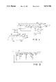
- FIG. 1 is a schematic drawing showing a simplified representation of the data discriminating circuit of the invention together with a marked sheet and drive means;
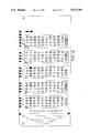
- FIG. 2 is a plan view of a typical marked card, such as used for lottery entry forms
- FIG. 3 is a signal diagram illustrating the read signal and the theshold signal in accordance with the invention.
- FIG. 4 is a detailed schematic drawing of a first embodiment of the data discriminating circuit of the invention.
- FIG. 5 is a signal diagram showing a theoretically perfect read signal and threshold signal, the threshold being switched at the time shown in broken lines;
- FIG. 6 is a signal diagram showing a typical read signal and threshold signal
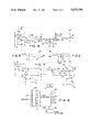
- FIG. 7 is a schematic diagram of an embodiment of the invention including threshold switching means and input signal level processing, for detecting the leading and trailing edges of a marked form;
- FIG. 8 is a block diagram showing an embodiment of the invention including a plurality of channels and an edge detection feature
- FIG. 1 shows a schematic and simplified representation of the data discriminating circuit of the invention as functionally related to a marked card 24 and drive means 28.
- the apparatus is shown and described herein primarily with reference to a reader for the hand marked entry cards used to make player selections in lottery games. However, such use is only one of many possibilities, including other forms of hand-marked sheets as well as printed or punched forms wherein reflective light variations due to marks or holes can be sensed for entering encoded data into a register.
- the illuminated surface of card 24 and/or a photodetector 30 are moved relative to one another, for example by a motor driven friction wheel 28.
- the light level (e.g., reflective or transmissive) variations 22 on the illuminated surface are correlated to the positions of potential marks and interpreted as players selections, UPC label codes, or other data entry information.
- FIG. 2 is a plan view of a typical marked card as used for a lottery entry form.
- the positions of potential marks are delineated by boxes on the card.
- Printed metering marks can be included, for example along the edge of the card, and used for triggering a sample of the light levels sensed along tracks or channels aligned in rows and columns.
- twenty tracks are provided for reading across the rows of marks and/or timing marks on the card, each track or channel having an individual illumination means, photodetector and processing circuit according to the invention.
- the illumination means and photodetector can be packaged together or can be separate elements.
- the circuit can be embodied wholly or partly in an integrated circuit.
- the photodetector and illumination means can be placed in close proximity to the data bearing card, or one or both can be optically connected to the data bearing card by fiber optic lines.
- the card 24 is moved relative to the photodetectors 30 by a drive means 28.
- the drive means could be arranged to move the detector while the card remains stationary, but typically the card is moved past a stationary bank of detectors.
- Sensing the data is complicated by the normal variation in the character and darkness of the marks which players place on the entry form cards, and also by the mechanical and electrical variations that inevitably occur in feeding, illuminating and reading the data. These variations include card flutter, namely the variation in spacing between the illuminated surface 24 and the illumination means and photodetector 30, resulting in corresponding variation in signal strength.
- the supply voltage to the detecting circuit varies with ripple on the power lines, loading of the power supply by the drive means 28 and other elements of the apparatus.
- the emission level of the illumination means and the sensitivity of the photodetector change with temperature and with aging, and vary from one element to another among the plurality of such elements employed for reading data on the respective tracks, i.e., the rows and columns of the card.
- the circuit of the invention as shown generally in FIG. 1 and in more detail in FIG. 4, is responsive to variations in the light level received.
- the level as detected by photosensor 30 is compared to a dynamically varying threshold maintained by averaging the signal produced by the photodetector for each of the tracks, using an integrator.
- FIG. 3 is a signal diagram illustrating the read signal and the threshold signal in accordance with the invention.
- the objective is to set the threshold level sufficiently close to the signal level that no marks 22 on the card 24 will be missed, but sufficiently below the signal level that none of the variations produced in the signal that are not due to marks will be interpreted erroneously as marks.
- This problem is complicated by the fact that the character and darkness of the marks varies substantially, for example as shown in the sample lottery entry card shown in FIG. 2.
- Read signal 26 (the upper of the two lines in FIG. 3) is characterized by a plurality of short term disturbances due to the above described effects such as power supply ripple or card flutter.
- the read signal can also vary over the longer term due to slower variations such as temperature and aging. If the threshold is set at a particular level which is optimized relative to the short term effects, such optimization will be lost eventually.
- the threshold level is arranged to vary as a percentage of a weighted average signal level for each of the tracks.
- the output 46 of the follower amplifier 40 is applied to a dual rate integrator 50, defined for example by a resistor 52 in series with the output 46 of follower 40, and a capacitor 54 and resistor 72 in parallel thereto.
- One or more diodes 56 are inserted between the follower and the integrator, thereby preventing the integrator from responding too quickly to a negative excursion in voltage at the output of the follower.
- the integrator preferably operates at different rates with respect to positive signals and negative signals, thus weighting the threshold comparison such that the detector reacts to negative signals in a more restrained manner than to positive signals.
- the voltage level increases or decreases exponentially over time to approach the voltage at the output 46.
- the rate of increase or decrease is a function of the time constants defined by the series resistance and parallel capacitance, and by the parallel resistance and parallel capacitance combinations, respectively, according to the functions: e -t/RsCp (for charging the capacitor through the series resistor), and e -t/RpCp (for discharging the capacitor through the parallel resistor).
- a short term change on the voltage at output 46 of follower 40 results in a slower change at the junction of the resistor 52 and capacitor 54, and the rate of change can be set separately for positive and negative going signals.
- the junction of the capacitor 54 and the resistors 52, 72 is connected as one input 62 to a comparator 60.
- the other input 64 is connected to the input 42 of the follower amplifier, i.e., to the signal produced by the photodetector.
- Integrator 50 is characterized by losses.
- the leakage of capacitor 50 and the load produced by the input to comparator 60 drain current from capacitor 50.
- These losses can be modeled as a second resistance in parallel with capacitor 54 and resistor 72, which resistances form a voltage divider together with the series resistance disposed between output 46 of follower 40 and the junction of resistor 52 and capacitor 54. Accordingly, the level of input 64 to comparator 60 maintains a percentage of the averaged (integrated) level of output 46.
- the threshold percentage can be set to any arbitrary level, preferably about 89-93% for hand-marked lottery entry cards, by choosing the corresponding values of resistor 52 and resistor 72 that produce the desired percentage in the voltage divider, taking into account the leakage resistance of the capacitor and the input impedance of comparator 60.
- the value of capacitor 54 is then chosen in view of the value of resistor 52, to give the desired time constant. Suitable exemplary values for these components are shown in FIG. 4.
- FIG. 4 is a detailed schematic drawing of a first embodiment of the data discriminating circuit of the invention, and also shows the particulars of the illumination means 96, which can be an LED, preferably emitting light in the red to near-infrared range.
- the illumination means 96 can be an LED, preferably emitting light in the red to near-infrared range.
- Light reflected by card 24 is received by photodetector 30, for example a phototransistor connected as an emitter follower.
- a decrease in reflected light e.g., due to the appearance of a darkened mark on card 24
- correspondingly decreases the extent to which the phototransistor conducts, thereby producing an increase in voltage at non-inverting input 42 to follower amplifier 40, and also at the output 46 of the follower.
- diode 56 By positioning diode 56 between the output of the follower 40 and the series resistor 52 of the integrator, a positive direction voltage follower is created and the follower output does not discharge the capacitor 54 during low excursions.
- the diode is placed within the feedback loop of the follower, whereby the voltage divider can set any arbitrary percentage of the input signal level for use in the threshold comparison (i.e., without the diode voltage drop to consider).
- Diode 56 conducts with a low series resistance when the output 46 is at a higher voltage than the integrator 50 because the diode 56 is then forward biased. When the voltage at follower output 46 is lower than the integrator voltage, the diode is reverse biased and its series resistance is much higher. Accordingly, diode 56 blocks discharge of the integrator through the follower output, allowing the capacitor to discharge through parallel resistor 72.
- the detector is preferably substantially more responsive to darkening (i.e., due to marks) than to lightening (i.e., due to other effects such as flutter).
- diode 56 causes the apparatus to quickly adapt to the required threshold for sensing marks on the card.
- Both the follower amplifier and the comparator are preferably high gain operational amplifiers. Suitable voltage supply particulars, decoupling capacitors and the like can be connected to the amplifiers in accordance with manufacturer specifications and as known in the art. As shown in FIG. 4, the output of the comparator can be clamped between ground and the positive DC voltage supply, preferably through a series resistor, to shift the level of the output 68 of comparator 60 to levels appropriate for digital inputs, for example for TTL or CMOS inputs. Due to its high gain, the output of the operational amplifier defining the comparator is always either high or low, thereby digitizing the signal.
- the output state of the comparator can be sampled or loaded into downstream digital circuit packages (not shown) at an appropriate instant, for example as determined by detection of timing marks printed on the card.
- the timing marks can likewise be detected using a channel of the apparatus according to the invention. Inasmuch as printed marks are more dependably detectable than hand written ones, it is furthermore possible to set a lower threshold for the channel used to detect timing marks than the approximately 89-93% level considered optimal for detecting handwritten marks.
- FIG. 5 is a signal diagram showing a theoretically perfect read signal 26 and threshold signal 26, and shows the effect of integrator 50 on the substantially digital (bi-level) perfect input signal which might result from a timing mark printed on the card, or a handwritten mark of sufficient size and uniform darkness to place the phototransistor in saturation during the passage of the mark.
- the threshold signal 66 is characterized by an exponential decay during the low state of input signal 26, and an exponential charging during the high state, such charging continuing until the threshold reaches the percentage of the high level defined by the voltage divider.
- the threshold level can be switchable in accordance with the alternative embodiment of the invention shown in FIG. 7.
- Such operation can be used to employ a different threshold when sensing the card edge, or for re-reading a card that was not successfully read at a different threshold.
- Switching occurs at the dotted line under control of external control elements (not shown).
- the threshold can be switched upwardly or downwardly as appropriate, and two or more discrete threshold levels can be made selectable.
- FIG. 7 three additional operational amplifiers are included to amplify and level shift a signal from the photodetector before feeding the signal into the data detector section.
- This initial processing of the signal allows a photodetector arranged to read one of the tracks on the marked form to be used to generate a signal that defines when a form is located beneath the photodetector.
- the output of this photodetector's channel remains true when the data bearing record is passing the remaining photodetectors in the apparatus and accordingly can be used as a gating signal to enable data detection only when the form is in position and valid data is expected.
- the circuit is somewhat similar to that of FIG. 4, namely including follower 40, comparator 60, integrator 50 and a voltage divider 80.
- the voltage divider in this case is affected by the serial resistance 74 of an additional serially connected diode 56, in this case located outside of the feedback loop of the follower amplifier, together with one or both of resistors 72, 84.
- the resistance from the integrator 50 to ground is substantially defined by the value of resistor 72.
- the resistance from the integrator to ground is defined substantially by the parallel resistance of resistors 72, 84. This has the effect of making the threshold of comparator 60 switchable as shown graphically in FIG. 5 at the dotted line.
- the signals appear substantially more like the signals shown in FIG. 6. Nevertheless, by adaptively controlling the threshold to a percentage of the average value of the input signal in accordance with the invention, it is possible to dependably detect handwritten marks on cards even where the marks vary in their character and darkness.
- FIG. 8 is a block diagram showing an embodiment of the invention including a plurality of channels and an edge detection feature for enabling reading of data during the presence of a form.
- the edge detector 132 can be used to enable a data detector circuit to read a timing track on the form or to supply a bi-level (digital) signal that defines the interval during which the marked form is being moved past the bank of photodetectors.
- the basic function of the apparatus is to convert the analog outputs of the sensing apparatus 120 into digital outputs 140, using a plurality of detector channels according to the invention, these channels forming the data detector block 130 in FIG. 8.
- the invention as disclosed and claimed herein is an apparatus for discriminating reflective variations 22 on an illuminated surface 24, including at least one photodetector 30 operable to produce an input signal 26 in response to reflections of the illuminated surface 24.
- a first amplifier 40 is connected as a follower amplifier, the first amplifier 40 having a non-inverting input 42 to which said input signal 26 is applied and an inverting input 44 connected to an output 46 of the first amplifier 40.
- An integrator 50 is connected to sense the output 46 of the first amplifier 40, the integrator 50 including a resistor 52 in series with the output 46 of the first amplifier 40 and a capacitor 54 in parallel with the resistor 52.
- a second amplifier 60 is connected as a comparator, the second amplifier 60 having a non-inverting input 62 and an inverting input 64, said non-inverting and inverting inputs 62, 64 being connected to the integrator 50 and to the non-inverting input 42 of the first amplifier 40, respectively.
- the integrator 50 defines a threshold level 66 of the comparator or second amplifier 60, an output 68 of the second amplifier 60 changing state in response to said input signal exceeding the threshold and the threshold being a predetermined proportion of a time-varying average of the input signal.
- a resistor 74 is included in parallel with the capacitor 54, the predetermined proportion being defined substantially by proportionate values of the resistor 52 in series with the capacitor 54 and the resistor 72 in parallel with the capacitor 54.
- a transistor or other switching means 82 can switch said resistance 72 between at least two discrete values, the predetermined proportion being thereby switchable and defined substantially by proportionate values of the resistor 52 in series with the capacitor 54 and the switchable resistance 84 in parallel with the capacitor 54.
- the photodetector 30 preferably includes one of a photodiode and a phototransistor connected between a positive DC level and said non-inverting input 42 of the first amplifier 40 through a series resistance 34 and a parallel resistance 36.
- a diode can be placed in series with the output of the follower amplifier to block discharge of the integrator through the follower amplifier.
- the integration rate defined by the integrator is preferably arranged such that the integrator is more quickly charged than discharged, allowing weighting in favor of detection of marks.
- the invention is likewise characterized as an apparatus for discriminating reflective variations on an illuminated surface 24, 90, the illuminated surface 24 having a plurality of tracks with potential reflective variations 22 occurring at discrete positions thereon.
- At least one photodetector 30 is provided for each of the tracks, each said photodetector 30 being operable to produce an input signal 26 for a respective one of the tracks in response to reflections of the illuminated surface 24, 90.
- a follower amplifier 40 for each of the tracks having a non-inverting input 42, an inverting input 44 and an output 46, said input signal 26 being applied to the non-inverting input 42, the output 46 being at least indirectly connected to the inverting input 44, whereby the output 46 follows the input signal 26.
- An integrator 50 for each of the tracks is connected to the output 46 of the follower amplifier, 40 the integrator 50 producing a time varying average of the output of the follower amplifier.
- a comparator 60 for each of the tracks has two inputs 62, 64 and an output 68, the output 68 changing state as a function of a comparison of levels of the two inputs, one of said two inputs being connected to the integrator 50 such that a threshold level 66 of the comparator 60 is determined by said time varying average, and another of the two inputs being connected at least indirectly to the input signal 26 from the photodetector 30.
- a rectifier diode 56 can be connected to the output 46 of the amplifier 40 defining the follower amplifier 40, preferably within a feedback loop of the follower. Resistors in series and parallel with a capacitor, respectively, define time constants for the integrator. The time constants can be different, preferably allowing a relatively faster response to excursions of the signal representing marks.
- a voltage divider 80 can be provided on said one of the two inputs 62, 64 to the comparator 60 connected to the integrator 50, the voltage divider 80 defining a predetermined proportion of the time varying average as the threshold level of the comparator 60.
- the predetermined proportion can be, for example, 89-95% of the time varying average, preferably approximately 93% of the time varying average.
- the predetermined proportion can be switchable to two or more selectable proportions by including means for switching at least one resistor of the voltage divider for changing the predetermined proportion of the time varying average.
- the predetermined proportion can be switchable between about 75% and about 93% of the time varying average.
- the switching means preferably includes a switchable resistance defined by a switching transistor and a resistor connected in series with one another, the switchable resistance being connected in parallel with the integrator, the voltage divider having a series resistance connected between the follower amplifier and the comparator and a parallel resistance connected in parallel with the switchable resistance.
- the illuminated surface is typically a manually marked sheet as used for player selection of lottery numbers on lottery entry forms, or other media wherein potential marks define tracks corresponding to rows disposed laterally and/or longitudinally along a feed direction of the sheet.
- the invention can be seen to be a method of discriminating one of marks and holes in a sheet, including feeding the sheet relatively along an array of photodetectors and illuminating the sheet at least in an area of the photodetectors; averaging an output signal from each of the photodetectors in the array; dividing the output signal as averaged to obtain a predetermined proportion of an average level of the output signal; comparing the output signal to the predetermined proportion of the average level for each of the photodetectors in the array; and, determining presence of said one of marks and holes by a result of said comparing step.
- the method also includes weighting the averaging of the output signal to respond more quickly to changes in the output signal in one of an increasing and decreasing direction thereof, whereby the comparison is made less sensitive to changes in an other of the increasing and decreasing direction.
- weighting the averaging of the output signal to respond more quickly to changes in the output signal in one of an increasing and decreasing direction thereof, whereby the comparison is made less sensitive to changes in an other of the increasing and decreasing direction.
- This can be accomplished by providing different time constants for an integrator used to accumulate the average.
- the predetermined proportion employed in comparing the signal level to the threshold i.e., integrated average
- Detectors according to this description can be used for both mark detection and form presence detection, the latter producing a signal for gating valid data from detectors used for mark detection.
Abstract
Description
Claims (10)
Priority Applications (1)
| Application Number | Priority Date | Filing Date | Title |
|---|---|---|---|
| US07/462,817 US5073700A (en) | 1990-01-10 | 1990-01-10 | Mark sense detector with variable threshold |
Applications Claiming Priority (1)
| Application Number | Priority Date | Filing Date | Title |
|---|---|---|---|
| US07/462,817 US5073700A (en) | 1990-01-10 | 1990-01-10 | Mark sense detector with variable threshold |
Publications (1)
| Publication Number | Publication Date |
|---|---|
| US5073700A true US5073700A (en) | 1991-12-17 |
Family
ID=23837867
Family Applications (1)
| Application Number | Title | Priority Date | Filing Date |
|---|---|---|---|
| US07/462,817 Expired - Fee Related US5073700A (en) | 1990-01-10 | 1990-01-10 | Mark sense detector with variable threshold |
Country Status (1)
| Country | Link |
|---|---|
| US (1) | US5073700A (en) |
Cited By (38)
| Publication number | Priority date | Publication date | Assignee | Title |
|---|---|---|---|---|
| US5164601A (en) * | 1988-06-22 | 1992-11-17 | Esselte Security Systems Ab | Method and apparatus for detecting marks on a paper web, using alternate set point values indicative of light intensity to identify marks and non-marks |
| US5270553A (en) * | 1992-12-22 | 1993-12-14 | Hewlett-Packard Company | Beginning-of-tape sensor with automatic threshold adjustment |
| US5293047A (en) * | 1991-08-13 | 1994-03-08 | Tohoku Ricoh Co., Ltd. | Method and an apparatus for detecting indices of paper based on a replaceable intermediate or average threshold value |
| US5392268A (en) * | 1991-07-18 | 1995-02-21 | Olympus Optical Co., Ltd. | Optical recording/reproducing apparatus for reproducing information of multiple tracks capable of correcting uneven illumination of the multiple tracks |
| US5420407A (en) * | 1993-09-17 | 1995-05-30 | National Computer Systems, Inc. | Adjustable read level threshold for optical mark scanning |
| US5503904A (en) * | 1993-01-19 | 1996-04-02 | Canon Kabushiki Kaisha | Invisible information recorded medium |
| US5530233A (en) * | 1994-06-30 | 1996-06-25 | Symbol Technologies, Inc. | Bar code scanner with quasi-retroreflective light collection |
| US5550362A (en) * | 1992-11-20 | 1996-08-27 | Intermec Corporation | Method and apparatus for calibrating a bar code scanner |
| WO1998020445A1 (en) * | 1996-11-08 | 1998-05-14 | National Computer Systems, Inc. | Optical scanning with calibrated pixel output |
| EP0979440A2 (en) * | 1997-04-16 | 2000-02-16 | Nova Controls, Inc. | Chemical dispensing system using keyboardless data entry |
| US6155491A (en) * | 1998-05-29 | 2000-12-05 | Welch Allyn Data Collection, Inc. | Lottery game ticket processing apparatus |
| US6357658B1 (en) | 1999-04-28 | 2002-03-19 | Peripheral Dynamics, Inc. | Apparatus and methods for scanning documents including OMR, bar-code, and image data |
| US6400912B1 (en) * | 2000-09-21 | 2002-06-04 | Toshiba Tec Kabushiki Kaisha | Image forming apparatus with detection of media and setting a threshold for the detector |
| US6444970B1 (en) * | 1998-06-26 | 2002-09-03 | Scimed Life Systems, Inc. | Miniature low-noise photodiode system |
| US20020142825A1 (en) * | 2001-03-27 | 2002-10-03 | Igt | Interactive game playing preferences |
| US20020181805A1 (en) * | 1999-06-22 | 2002-12-05 | Loeb Helen S. | Apparatus and methods for image scanning of variable sized documents having variable orientations |
| US20030034393A1 (en) * | 2000-11-20 | 2003-02-20 | Chung Kevin Kwong-Tai | Electronic voting apparatus, system and method |
| US20030039320A1 (en) * | 2001-05-07 | 2003-02-27 | Axel Christoph | Device and method for determining the respectively present level of a digital signal |
| US6628842B1 (en) * | 1999-06-22 | 2003-09-30 | Fuji Photo Film Co., Ltd. | Image processing method and apparatus |
| US20040002379A1 (en) * | 2002-06-27 | 2004-01-01 | Igt | Scan based configuration control in a gaming environment |
| US20040046021A1 (en) * | 2000-11-20 | 2004-03-11 | Chung Kevin Kwong-Tai | Electronic voting apparatus, system and method |
| US6732916B1 (en) | 2000-04-14 | 2004-05-11 | Gtech Rhode Island Corporation | Automated ticket cancellation device and process for canceling uniquely numbered tickets |
| US20050159206A1 (en) * | 2001-04-06 | 2005-07-21 | Anoto Ab | Method for performing games |
| US20060169778A1 (en) * | 2000-11-20 | 2006-08-03 | Chung Kevin K | Electronic voting apparatus, system and method |
| US20070060302A1 (en) * | 2005-08-17 | 2007-03-15 | Igt | Scan based configuration control in a gaming environment |
| US20080101803A1 (en) * | 2006-10-31 | 2008-05-01 | Kok Keong Richard Lum | High dynamic range optical receiver |
| US7614553B2 (en) | 2001-10-01 | 2009-11-10 | Avante International Technology, Inc. | Method for reading an optically readable sheet |
| US20090287137A1 (en) * | 1996-11-21 | 2009-11-19 | Boston Scientific Corporation | Mucosal ablation |
| US7635087B1 (en) | 2001-10-01 | 2009-12-22 | Avante International Technology, Inc. | Method for processing a machine readable ballot and ballot therefor |
| US20100252628A1 (en) * | 2009-04-07 | 2010-10-07 | Kevin Kwong-Tai Chung | Manual recount process using digitally imaged ballots |
| US7828215B2 (en) | 2001-10-01 | 2010-11-09 | Avante International Technology, Inc. | Reader for an optically readable ballot |
| US7862427B2 (en) | 2004-10-04 | 2011-01-04 | Igt | Wide area progressive jackpot system and methods |
| US7883413B2 (en) | 2001-03-27 | 2011-02-08 | Igt | Interactive game playing preferences |
| US8066184B2 (en) | 2008-04-30 | 2011-11-29 | Avante International Technology, Inc. | Optically readable marking sheet and reading apparatus and method therefor |
| US8261986B2 (en) | 2009-10-21 | 2012-09-11 | Kevin Kwong-Tai Chung | System and method for decoding an optically readable markable sheet and markable sheet therefor |
| US8480466B2 (en) | 2001-03-27 | 2013-07-09 | Igt | Method and apparatus for previewing a game |
| US8602882B2 (en) | 2004-10-04 | 2013-12-10 | Igt | Jackpot interfaces and services on a gaming machine |
| US8840022B1 (en) | 2013-03-15 | 2014-09-23 | Election Systems & Software, Llc | System and method for decoding marks on a response sheet |
Citations (17)
| Publication number | Priority date | Publication date | Assignee | Title |
|---|---|---|---|---|
| US3303329A (en) * | 1962-12-03 | 1967-02-07 | Ibm | Mark sensing system |
| US3692983A (en) * | 1970-07-14 | 1972-09-19 | Honeywell Inf Systems | Automatic threshold control circuit for optical card readers and sorters |
| US3747066A (en) * | 1971-08-23 | 1973-07-17 | Ocr Syst Inc | Optical scanner and signal processing system |
| US3751636A (en) * | 1972-06-01 | 1973-08-07 | Rca Corp | Signal transition detection circuit |
| US3814944A (en) * | 1973-05-24 | 1974-06-04 | Computer Design Corp | Mark sense card reader |
| US3846623A (en) * | 1972-02-22 | 1974-11-05 | Nixdorf Computer Ag | Scanning means |
| US3872329A (en) * | 1974-03-07 | 1975-03-18 | Rca Corp | Radiation sensing circuit |
| US3949233A (en) * | 1974-08-15 | 1976-04-06 | Pitney-Bowes, Inc. | Hand held bar code reader with constant linear amplifier output |
| US4047023A (en) * | 1976-08-09 | 1977-09-06 | Scientific Technology Inc. | Color mark detector with pulsed source and synchronous demodulation |
| US4162408A (en) * | 1977-10-17 | 1979-07-24 | Bourns, Inc. | Optical mark sense detector |
| US4196845A (en) * | 1977-04-15 | 1980-04-08 | Vickers Limited | Bar-coded data input terminals |
| US4230265A (en) * | 1979-05-07 | 1980-10-28 | Transaction Technology, Inc. | Adaptive threshold optical reader |
| US4335301A (en) * | 1979-09-27 | 1982-06-15 | Interface Mechanisms, Inc. | Wave shaping circuit for electro-optical code readers |
| US4356389A (en) * | 1980-06-27 | 1982-10-26 | Motorola Inc. | Bar code scanner interface |
| US4578568A (en) * | 1982-10-28 | 1986-03-25 | Casio Computer Co., Ltd. | Data reader |
| US4724307A (en) * | 1986-04-29 | 1988-02-09 | Gtech Corporation | Marked card reader |
| US4870262A (en) * | 1987-01-06 | 1989-09-26 | Alps Electric Co., Ltd. | Signal processing apparatus and binary encoder circuit for the same |
-
1990
- 1990-01-10 US US07/462,817 patent/US5073700A/en not_active Expired - Fee Related
Patent Citations (17)
| Publication number | Priority date | Publication date | Assignee | Title |
|---|---|---|---|---|
| US3303329A (en) * | 1962-12-03 | 1967-02-07 | Ibm | Mark sensing system |
| US3692983A (en) * | 1970-07-14 | 1972-09-19 | Honeywell Inf Systems | Automatic threshold control circuit for optical card readers and sorters |
| US3747066A (en) * | 1971-08-23 | 1973-07-17 | Ocr Syst Inc | Optical scanner and signal processing system |
| US3846623A (en) * | 1972-02-22 | 1974-11-05 | Nixdorf Computer Ag | Scanning means |
| US3751636A (en) * | 1972-06-01 | 1973-08-07 | Rca Corp | Signal transition detection circuit |
| US3814944A (en) * | 1973-05-24 | 1974-06-04 | Computer Design Corp | Mark sense card reader |
| US3872329A (en) * | 1974-03-07 | 1975-03-18 | Rca Corp | Radiation sensing circuit |
| US3949233A (en) * | 1974-08-15 | 1976-04-06 | Pitney-Bowes, Inc. | Hand held bar code reader with constant linear amplifier output |
| US4047023A (en) * | 1976-08-09 | 1977-09-06 | Scientific Technology Inc. | Color mark detector with pulsed source and synchronous demodulation |
| US4196845A (en) * | 1977-04-15 | 1980-04-08 | Vickers Limited | Bar-coded data input terminals |
| US4162408A (en) * | 1977-10-17 | 1979-07-24 | Bourns, Inc. | Optical mark sense detector |
| US4230265A (en) * | 1979-05-07 | 1980-10-28 | Transaction Technology, Inc. | Adaptive threshold optical reader |
| US4335301A (en) * | 1979-09-27 | 1982-06-15 | Interface Mechanisms, Inc. | Wave shaping circuit for electro-optical code readers |
| US4356389A (en) * | 1980-06-27 | 1982-10-26 | Motorola Inc. | Bar code scanner interface |
| US4578568A (en) * | 1982-10-28 | 1986-03-25 | Casio Computer Co., Ltd. | Data reader |
| US4724307A (en) * | 1986-04-29 | 1988-02-09 | Gtech Corporation | Marked card reader |
| US4870262A (en) * | 1987-01-06 | 1989-09-26 | Alps Electric Co., Ltd. | Signal processing apparatus and binary encoder circuit for the same |
Cited By (62)
| Publication number | Priority date | Publication date | Assignee | Title |
|---|---|---|---|---|
| US5164601A (en) * | 1988-06-22 | 1992-11-17 | Esselte Security Systems Ab | Method and apparatus for detecting marks on a paper web, using alternate set point values indicative of light intensity to identify marks and non-marks |
| US5392268A (en) * | 1991-07-18 | 1995-02-21 | Olympus Optical Co., Ltd. | Optical recording/reproducing apparatus for reproducing information of multiple tracks capable of correcting uneven illumination of the multiple tracks |
| US5293047A (en) * | 1991-08-13 | 1994-03-08 | Tohoku Ricoh Co., Ltd. | Method and an apparatus for detecting indices of paper based on a replaceable intermediate or average threshold value |
| US5550362A (en) * | 1992-11-20 | 1996-08-27 | Intermec Corporation | Method and apparatus for calibrating a bar code scanner |
| US5270553A (en) * | 1992-12-22 | 1993-12-14 | Hewlett-Packard Company | Beginning-of-tape sensor with automatic threshold adjustment |
| US6153879A (en) * | 1993-01-19 | 2000-11-28 | Canon Kabushiki Kaisha | Invisible information detecting apparatus |
| US5503904A (en) * | 1993-01-19 | 1996-04-02 | Canon Kabushiki Kaisha | Invisible information recorded medium |
| US5420407A (en) * | 1993-09-17 | 1995-05-30 | National Computer Systems, Inc. | Adjustable read level threshold for optical mark scanning |
| US5711673A (en) * | 1993-09-17 | 1998-01-27 | National Computer Systems | Method for interpreting a plurality of response marks on a scannable surface |
| US5530233A (en) * | 1994-06-30 | 1996-06-25 | Symbol Technologies, Inc. | Bar code scanner with quasi-retroreflective light collection |
| US6459509B1 (en) | 1996-11-08 | 2002-10-01 | National Computer Systems, Inc. | Optical scanning device having a calibrated pixel output and a method for calibrating such a device |
| WO1998020445A1 (en) * | 1996-11-08 | 1998-05-14 | National Computer Systems, Inc. | Optical scanning with calibrated pixel output |
| US6552829B1 (en) | 1996-11-08 | 2003-04-22 | Ncs Pearson, Inc. | Optical scanning device having a calibrated pixel output and method for calibrating such a device |
| US20090287137A1 (en) * | 1996-11-21 | 2009-11-19 | Boston Scientific Corporation | Mucosal ablation |
| EP0979440A2 (en) * | 1997-04-16 | 2000-02-16 | Nova Controls, Inc. | Chemical dispensing system using keyboardless data entry |
| EP0979440A4 (en) * | 1997-04-16 | 2003-06-25 | Nova Controls Inc | Chemical dispensing system using keyboardless data entry |
| US6155491A (en) * | 1998-05-29 | 2000-12-05 | Welch Allyn Data Collection, Inc. | Lottery game ticket processing apparatus |
| US6405929B1 (en) | 1998-05-29 | 2002-06-18 | Hand Held Products, Inc. | Material detection systems for security documents |
| US6304660B1 (en) | 1998-05-29 | 2001-10-16 | Welch Allyn Data Collection, Inc. | Apparatuses for processing security documents |
| US6444970B1 (en) * | 1998-06-26 | 2002-09-03 | Scimed Life Systems, Inc. | Miniature low-noise photodiode system |
| US6357658B1 (en) | 1999-04-28 | 2002-03-19 | Peripheral Dynamics, Inc. | Apparatus and methods for scanning documents including OMR, bar-code, and image data |
| US6628842B1 (en) * | 1999-06-22 | 2003-09-30 | Fuji Photo Film Co., Ltd. | Image processing method and apparatus |
| US20020181805A1 (en) * | 1999-06-22 | 2002-12-05 | Loeb Helen S. | Apparatus and methods for image scanning of variable sized documents having variable orientations |
| US6732916B1 (en) | 2000-04-14 | 2004-05-11 | Gtech Rhode Island Corporation | Automated ticket cancellation device and process for canceling uniquely numbered tickets |
| US6400912B1 (en) * | 2000-09-21 | 2002-06-04 | Toshiba Tec Kabushiki Kaisha | Image forming apparatus with detection of media and setting a threshold for the detector |
| US7461787B2 (en) | 2000-11-20 | 2008-12-09 | Avante International Technology, Inc. | Electronic voting apparatus, system and method |
| US20030034393A1 (en) * | 2000-11-20 | 2003-02-20 | Chung Kevin Kwong-Tai | Electronic voting apparatus, system and method |
| US7422150B2 (en) | 2000-11-20 | 2008-09-09 | Avante International Technology, Inc. | Electronic voting apparatus, system and method |
| US7431209B2 (en) | 2000-11-20 | 2008-10-07 | Avante International Technology, Inc. | Electronic voting apparatus, system and method |
| US20040046021A1 (en) * | 2000-11-20 | 2004-03-11 | Chung Kevin Kwong-Tai | Electronic voting apparatus, system and method |
| US20060169778A1 (en) * | 2000-11-20 | 2006-08-03 | Chung Kevin K | Electronic voting apparatus, system and method |
| US20020142825A1 (en) * | 2001-03-27 | 2002-10-03 | Igt | Interactive game playing preferences |
| US7883413B2 (en) | 2001-03-27 | 2011-02-08 | Igt | Interactive game playing preferences |
| US7918738B2 (en) | 2001-03-27 | 2011-04-05 | Igt | Interactive game playing preferences |
| US8435105B2 (en) | 2001-03-27 | 2013-05-07 | Igt | Interactive game playing preferences |
| US8480466B2 (en) | 2001-03-27 | 2013-07-09 | Igt | Method and apparatus for previewing a game |
| US7722453B2 (en) | 2001-03-27 | 2010-05-25 | Igt | Interactive game playing preferences |
| US20050159206A1 (en) * | 2001-04-06 | 2005-07-21 | Anoto Ab | Method for performing games |
| US7976370B2 (en) * | 2001-04-06 | 2011-07-12 | Anoto Ab | Method for performing games |
| US20030039320A1 (en) * | 2001-05-07 | 2003-02-27 | Axel Christoph | Device and method for determining the respectively present level of a digital signal |
| US7828215B2 (en) | 2001-10-01 | 2010-11-09 | Avante International Technology, Inc. | Reader for an optically readable ballot |
| US7635088B2 (en) | 2001-10-01 | 2009-12-22 | Avante International Technology, Inc. | Electronic voting method and system employing a printed machine readable ballot |
| US7988047B2 (en) | 2001-10-01 | 2011-08-02 | Avante International Technology, Inc. | Method for decoding an optically readable sheet |
| US7635087B1 (en) | 2001-10-01 | 2009-12-22 | Avante International Technology, Inc. | Method for processing a machine readable ballot and ballot therefor |
| US7614553B2 (en) | 2001-10-01 | 2009-11-10 | Avante International Technology, Inc. | Method for reading an optically readable sheet |
| US7975920B2 (en) | 2001-10-01 | 2011-07-12 | Avante International Technology, Inc. | Electronic voting method and system employing a machine readable ballot envelope |
| US7909699B2 (en) * | 2002-06-27 | 2011-03-22 | Igt | Scan based configuration control in a gaming environment |
| US20040002379A1 (en) * | 2002-06-27 | 2004-01-01 | Igt | Scan based configuration control in a gaming environment |
| US9311772B2 (en) | 2004-10-04 | 2016-04-12 | Igt | Jackpot interfaces and services on a gaming machine |
| US7862427B2 (en) | 2004-10-04 | 2011-01-04 | Igt | Wide area progressive jackpot system and methods |
| US9640035B2 (en) | 2004-10-04 | 2017-05-02 | Igt | Jackpot interfaces and services on a gaming machine |
| US8602882B2 (en) | 2004-10-04 | 2013-12-10 | Igt | Jackpot interfaces and services on a gaming machine |
| US8323103B2 (en) | 2005-08-17 | 2012-12-04 | Igt | Scan based configuration control in a gaming environment |
| US20070060302A1 (en) * | 2005-08-17 | 2007-03-15 | Igt | Scan based configuration control in a gaming environment |
| US20090149245A1 (en) * | 2005-08-17 | 2009-06-11 | Igt | Scan based configuration control in a gaming environment |
| US20080101803A1 (en) * | 2006-10-31 | 2008-05-01 | Kok Keong Richard Lum | High dynamic range optical receiver |
| US7474978B2 (en) * | 2006-10-31 | 2009-01-06 | Avago Technologies Ecbu Ip (Singapore) Pte. Ltd. | High dynamic range optical receiver |
| US8066184B2 (en) | 2008-04-30 | 2011-11-29 | Avante International Technology, Inc. | Optically readable marking sheet and reading apparatus and method therefor |
| US8261985B2 (en) | 2009-04-07 | 2012-09-11 | Avante Corporation Limited | Manual recount process using digitally imaged ballots |
| US20100252628A1 (en) * | 2009-04-07 | 2010-10-07 | Kevin Kwong-Tai Chung | Manual recount process using digitally imaged ballots |
| US8261986B2 (en) | 2009-10-21 | 2012-09-11 | Kevin Kwong-Tai Chung | System and method for decoding an optically readable markable sheet and markable sheet therefor |
| US8840022B1 (en) | 2013-03-15 | 2014-09-23 | Election Systems & Software, Llc | System and method for decoding marks on a response sheet |
Similar Documents
| Publication | Publication Date | Title |
|---|---|---|
| US5073700A (en) | Mark sense detector with variable threshold | |
| US4088265A (en) | Adaptable mark/hole sensing arrangement for card reader apparatus | |
| US4724307A (en) | Marked card reader | |
| US5248872A (en) | Device for optically reading marked ballots using infrared and red emitters | |
| US3820068A (en) | Background reference level system and method for document scanners | |
| CA1216361A (en) | Color-sensitive currency verifier | |
| US4189235A (en) | Test device for dynamically measuring the degree of dirt accumulation on bank-notes | |
| EP0668576A2 (en) | Bill discriminating apparatus for bill handling machine | |
| US3890221A (en) | Translucency/opaque sorting | |
| EP0427528A2 (en) | Bar code readers | |
| US4219737A (en) | Self regulating microfilm frame detection circuit | |
| US7068861B2 (en) | Device and method for inspecting markings | |
| US6359287B1 (en) | Apparatus for detecting an edge of a document | |
| US4162408A (en) | Optical mark sense detector | |
| US4295040A (en) | Detector arrangement for data-card readers | |
| US4323774A (en) | Circuit for reflective mode optical reader | |
| CA1295711C (en) | Scannable document velocity detector | |
| CA1115842A (en) | High resolution optical position code detector for information recorded on record carrier partially in humanly intelligible form | |
| GB2130362A (en) | Optical registration sensor. | |
| JP2001175799A (en) | Photodetector device, brightness/darkness information code reader and its adjusting method | |
| EP0049388B1 (en) | Video signal detector | |
| NL7906448A (en) | OPTICAL READING DEVICE. | |
| JP3685662B2 (en) | IC card identification device | |
| US3539778A (en) | Photoelectric reader | |
| JPH05274514A (en) | Instrument for measuring diameter of coin |
Legal Events
| Date | Code | Title | Description |
|---|---|---|---|
| AS | Assignment |
Owner name: GTECH CORPORATION, RHODE ISLAND Free format text: ASSIGNMENT OF ASSIGNORS INTEREST.;ASSIGNOR:D'ONOFRIO, ENZO D.;REEL/FRAME:005215/0119 Effective date: 19900109 |
|
| AS | Assignment |
Owner name: GTECH CORPORATION, RHODE ISLAND Free format text: RELEASED BY SECURED PARTY;ASSIGNOR:WELLS FARGO BANK, N.A.;REEL/FRAME:006327/0245 Effective date: 19920729 |
|
| FEPP | Fee payment procedure |
Free format text: PAYOR NUMBER ASSIGNED (ORIGINAL EVENT CODE: ASPN); ENTITY STATUS OF PATENT OWNER: LARGE ENTITY |
|
| FPAY | Fee payment |
Year of fee payment: 4 |
|
| AS | Assignment |
Owner name: GTECH RHODE ISLAND CORPORATION, RHODE ISLAND Free format text: ASSIGNMENT OF ASSIGNORS INTEREST;ASSIGNOR:GTECH CORPORATION;REEL/FRAME:009857/0001 Effective date: 19990217 |
|
| REMI | Maintenance fee reminder mailed | ||
| LAPS | Lapse for failure to pay maintenance fees | ||
| FP | Lapsed due to failure to pay maintenance fee |
Effective date: 19991217 |
|
| STCH | Information on status: patent discontinuation |
Free format text: PATENT EXPIRED DUE TO NONPAYMENT OF MAINTENANCE FEES UNDER 37 CFR 1.362 |