US5081699A - Program ahead file transfer in a reproduction machine - Google Patents
Program ahead file transfer in a reproduction machine Download PDFInfo
- Publication number
- US5081699A US5081699A US07/252,471 US25247188A US5081699A US 5081699 A US5081699 A US 5081699A US 25247188 A US25247188 A US 25247188A US 5081699 A US5081699 A US 5081699A
- Authority
- US
- United States
- Prior art keywords
- memory
- job
- program
- machine
- programming
- Prior art date
- Legal status (The legal status is an assumption and is not a legal conclusion. Google has not performed a legal analysis and makes no representation as to the accuracy of the status listed.)
- Expired - Lifetime
Links
- 238000012546 transfer Methods 0.000 title claims abstract description 48
- 230000015654 memory Effects 0.000 claims abstract description 73
- 238000000034 method Methods 0.000 claims abstract description 18
- 238000012545 processing Methods 0.000 claims description 16
- 230000006870 function Effects 0.000 claims description 15
- 230000003213 activating effect Effects 0.000 claims description 3
- 238000004519 manufacturing process Methods 0.000 claims description 3
- 230000015572 biosynthetic process Effects 0.000 claims 2
- 238000005755 formation reaction Methods 0.000 claims 2
- 230000003993 interaction Effects 0.000 claims 1
- 230000002452 interceptive effect Effects 0.000 claims 1
- 238000004088 simulation Methods 0.000 claims 1
- PWPJGUXAGUPAHP-UHFFFAOYSA-N lufenuron Chemical compound C1=C(Cl)C(OC(F)(F)C(C(F)(F)F)F)=CC(Cl)=C1NC(=O)NC(=O)C1=C(F)C=CC=C1F PWPJGUXAGUPAHP-UHFFFAOYSA-N 0.000 description 22
- 230000037361 pathway Effects 0.000 description 19
- 238000003384 imaging method Methods 0.000 description 8
- 238000003860 storage Methods 0.000 description 7
- 230000032258 transport Effects 0.000 description 7
- 230000009467 reduction Effects 0.000 description 6
- 239000011230 binding agent Substances 0.000 description 5
- 230000008859 change Effects 0.000 description 5
- 239000000843 powder Substances 0.000 description 5
- 238000003825 pressing Methods 0.000 description 5
- 238000012549 training Methods 0.000 description 4
- 238000012552 review Methods 0.000 description 3
- 238000004891 communication Methods 0.000 description 2
- 238000011161 development Methods 0.000 description 2
- 238000010586 diagram Methods 0.000 description 2
- 230000008570 general process Effects 0.000 description 2
- 238000012423 maintenance Methods 0.000 description 2
- 238000012986 modification Methods 0.000 description 2
- 230000004048 modification Effects 0.000 description 2
- 239000002245 particle Substances 0.000 description 2
- 238000009966 trimming Methods 0.000 description 2
- 230000006399 behavior Effects 0.000 description 1
- 230000008901 benefit Effects 0.000 description 1
- 230000002457 bidirectional effect Effects 0.000 description 1
- 238000004140 cleaning Methods 0.000 description 1
- 230000001143 conditioned effect Effects 0.000 description 1
- 238000012937 correction Methods 0.000 description 1
- 230000001934 delay Effects 0.000 description 1
- 230000009977 dual effect Effects 0.000 description 1
- 230000000694 effects Effects 0.000 description 1
- 239000008187 granular material Substances 0.000 description 1
- 239000000463 material Substances 0.000 description 1
- 230000007246 mechanism Effects 0.000 description 1
- 230000003287 optical effect Effects 0.000 description 1
- 230000002093 peripheral effect Effects 0.000 description 1
- 238000002360 preparation method Methods 0.000 description 1
- 230000001105 regulatory effect Effects 0.000 description 1
- 230000004044 response Effects 0.000 description 1
- 230000000717 retained effect Effects 0.000 description 1
- 239000007787 solid Substances 0.000 description 1
- 238000010792 warming Methods 0.000 description 1
- 229910052724 xenon Inorganic materials 0.000 description 1
- FHNFHKCVQCLJFQ-UHFFFAOYSA-N xenon atom Chemical compound [Xe] FHNFHKCVQCLJFQ-UHFFFAOYSA-N 0.000 description 1
Images


Classifications
-
- G—PHYSICS
- G03—PHOTOGRAPHY; CINEMATOGRAPHY; ANALOGOUS TECHNIQUES USING WAVES OTHER THAN OPTICAL WAVES; ELECTROGRAPHY; HOLOGRAPHY
- G03G—ELECTROGRAPHY; ELECTROPHOTOGRAPHY; MAGNETOGRAPHY
- G03G15/00—Apparatus for electrographic processes using a charge pattern
- G03G15/50—Machine control of apparatus for electrographic processes using a charge pattern, e.g. regulating differents parts of the machine, multimode copiers, microprocessor control
- G03G15/5016—User-machine interface; Display panels; Control console
- G03G15/502—User-machine interface; Display panels; Control console relating to the structure of the control menu, e.g. pop-up menus, help screens
-
- G—PHYSICS
- G06—COMPUTING; CALCULATING OR COUNTING
- G06K—GRAPHICAL DATA READING; PRESENTATION OF DATA; RECORD CARRIERS; HANDLING RECORD CARRIERS
- G06K15/00—Arrangements for producing a permanent visual presentation of the output data, e.g. computer output printers
-
- G—PHYSICS
- G03—PHOTOGRAPHY; CINEMATOGRAPHY; ANALOGOUS TECHNIQUES USING WAVES OTHER THAN OPTICAL WAVES; ELECTROGRAPHY; HOLOGRAPHY
- G03G—ELECTROGRAPHY; ELECTROPHOTOGRAPHY; MAGNETOGRAPHY
- G03G2215/00—Apparatus for electrophotographic processes
- G03G2215/00025—Machine control, e.g. regulating different parts of the machine
- G03G2215/00126—Multi-job machines
-
- G—PHYSICS
- G06—COMPUTING; CALCULATING OR COUNTING
- G06K—GRAPHICAL DATA READING; PRESENTATION OF DATA; RECORD CARRIERS; HANDLING RECORD CARRIERS
- G06K2215/00—Arrangements for producing a permanent visual presentation of the output data
- G06K2215/0082—Architecture adapted for a particular function
Definitions
- the invention relates to a system for pre-programming reproduction machines such as copiers and printers, and more particularly, to pre-programming file transfer and storage functions for such reproduction machines.
- a suitable interface must not only provide the controls, displays, and messages necessary to activate, program, monitor, and maintain the machine, but must do so in an efficient, relatively simple, and straightforward way. For if the user interface fails in this respect, the abilities that were designed and built into the machine and which the machine owner pays for, may never be realized.
- a modern sophisticated copier may present the operator with a large and confusing display of a large number of additional switches, buttons, dials, lights, instructions, etc..
- the operator may have to repeat this entire sequence of manual switch control steps for each desired copying job, even if that job is the same as ones previously run, e.g., a routine but unique printing job, such as a regular report, periodical, etc. If different copying functions or features are to be provided for different documents in a set or stack of documents to be copied it may be additionally necessary to interrupt each copying run and the feeding of the documents several times in order to change or reset various switches settings to the different processing desired.
- the Xerox 5700 Electronic Printing System incorporates a touch control CRT screen providing button, key, and window images on the screen combined with text to give concise instructions to the operator.
- This system accepts magnetic cards, cassettes, and disks that store the documents to be printed and also the magnetic media can store control information to specify the output format for printing or to invoke special features such as merging or interleaving.
- the system software translates the coded data, formats the page, and generates the hard copy locally, or the system can transmit the data via a communication link to remote 5700 printing sites.
- U.S. Pat. No. 4,711,556 discloses a copying machine that allows for inputting copying instructions, means for temporary storage of these instructions, a display of these values, an interrupt mode that will let the operator input different copying instructions, a readout of the new instructions, and a means to return to the original mode settings once the interrupt is completed.
- U.S. Pat. No. 4,711,560 discloses a copier which functions according to a sequence control program stored on floppy disk and loaded by a user.
- the floppy disk can also contain a diagnostic program to facilitate maintenance, and further act as a key to prevent unauthorized use of the copier.
- U.S. Pat. No. 4,742,483 discloses a laser printer including a microprocessor to read data or program information from a cartridge loaded by a user. A special maintenance operating system on the cartridge runs the printer through automatic routines to be checked by a technician.
- U.S. Pat. No., 4,248,528 discloses a control system in which pre-printed and operator marked control sheets are fed past an optical scanner connected to the control system and the documents are copied according to the instructions on the control sheets.
- U.S. Pat. No. 4,453,821 discloses a technique to configure a copier prior to a production run including a programmable, non-volatile memory for storing information corresponding to at least two different set-up configurations and a mechanism for selecting one of these configurations and configuring the copier in accordance with the selected configuration.
- U.S. Pat. No. 4,310,235 discloses an operator console, a card reader, and a control for feeding pre-programming marked cards to the card reader for storing the programming information into RAM memory.
- a job stream feature permits the operator to place a plurality of different jobs into the machine for automatic reproduction and a job exception feature allows the machine to be automatically conditioned to deviate from the normal reproduction run.
- Features can also be programmed at the operator console, but the console inputs are inhibited once the programmed card has been inserted.
- An object of the present invention is to provide a technique for pre-programming a reproduction machine for a plurality of future jobs involving a variety of machine features and requirements in a plurality of job slots in memory, and to be able to transfer job requirements or modified job requirements between job slots or to be able to transfer the job requirements to a portable storage media for transfer to and pre-program another machine.
- the present invention is concerned with a technique for pre-programming a reproduction machine at a console screen for a plurality of complex jobs by simulating a plurality of pre-programming slots in memory and machine features for each slot corresponding to required job runs and automatically storing the selected features in the pre-programming slots, including the means to transfer the stored features from one memory slot to another memory slot and the means to transfer the stored features to a removable media such as a floppy disk.
- the floppy disk can be inserted into another reproduction machine to automatically pre-program that machine for a plurality of job runs.
- FIG. 1 is an isometric view of an illustrative reproduction machine incorporating the touch dialogue User Interface (U.I.) of the present invention
- FIG. 2 is a schematic elevational view depicting various operating components and sub-systems of the machine shown in FIG. 1;
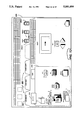
- FIG. 3 is a block diagram of the operating control systems and memory for the machine shown in FIG. 1;
- FIG. 4 is a more detailed block diagram of the operating control system of FIG. 3;
- FIG. 5 is a schematic elevational view showing the finishing sub-system of the machine shown in FIG. 1;
- FIG. 6 is a front view of the U.I. color touch monitor showing the soft button display screen and hard button control panel;
- FIG. 7 is a front view of the touch monitor screen with the principal elements of the soft touch dialogue displayed
- FIG. 8 is an isometric view showing the touch control LED and photodiode pwb's bordering the monitor screen
- FIG. 9 is a flow chart depicting the U.I. operating states
- FIG. 10 is a front view depicting the touch monitor screen display in the CURRENT job mode following touch selection of the STANDARD file folder;
- FIG. 11 is a front view depicting the touch monitor screen display in the CURRENT job mode following touch selection of the FANFOLD file folder;
- FIG. 12 is a front view depicting the touch monitor screen display in the CURRENT job mode following touch selection of the OVERSIZED file folder.
- FIG. 13 is a front view of the touch monitor screen shown in FIG. 17 depicting the touch selection icons that are displayed in the work area as a result of touch selection of the PAPER icon on the PROGRAM scorecard;
- FIG. 14 is a front view of the touch monitor screen shown in FIG. 10 depicting the touch selection icons that are displayed in the work area as a result of touch selection of the REDUCE/ENLARGE icon on the PROGRAM scorecard;
- FIG. 15 is a front view of the touch monitor screen shown in FIG. 10 depicting the touch selection icons that are displayed in the work area as a result of touch selection of the SIDES IMAGED icon on the PROGRAM scorecard;
- FIG. 16 is a front view of the touch monitor screen shown in FIG. 10 depicting the touch selection icons that are displayed in the work area as a result of touch selection of the SHIFT icon on the PROGRAM scorecard;
- FIG. 17 is a front view of the touch monitor screen shown in FIG. 10 depicting the touch selection icons that are displayed in the work area as a result of touch selection of the TRIM icon on the PROGRAM scorecard;
- FIG. 18 is a front view of the touch monitor screen shown in FIG. 10 depicting the touch selection icons that are displayed in the work area as a result of touch selection of the COPY QUALITY icon on the PROGRAM scorecard;
- FIG. 19 is a front view of the touch monitor screen depicting the touch selection icons that are displayed in the work area as a result of touch selection of the SPECIAL CONTROL icon shown in FIG. 18;
- FIG. 20 is a front view of the touch monitor screen shown in FIG. 10 depicting the touch selection icons that are displayed in the work area as a result of touch selection of the OUTPUT icon on the PROGRAM scorecard;
- FIG. 21 is a front view of the touch monitor screen shown in FIG. 10 depicting the touch selection icons that are displayed in the work area as a result of touch selection of the RETRIEVE PROGRAMS icon on the PROGRAM scorecard;
- FIG. 22 is a front view of the touch monitor screen shown in FIG. 10 depicting the touch selection exception programming icons that are displayed on selection of the EXCEPTION scorecard;
- FIG. 23 is a front view of the touch monitor screen shown in FIG. 10 depicting the touch selection pre-programming feature in accordance with the present invention.
- FIGS. 1, 2, and 3 there is shown an electrophotographic reproduction machine 5 composed of a plurality of programmable components and sub-systems which cooperate to carry out the copying or printing job programmed through the touch dialogue User Interface (U.I.) of the present invention.
- U.I. User Interface
- Machine 5 employs a photoconductive belt 10.
- Belt 10 is entrained about stripping roller 14, tensioning roller 16, idler rollers 18, and drive roller 20.
- Drive roller 20 is rotated by a motor coupled thereto by suitable means such as a belt drive. As roller 20 rotates, it advances belt 10 in the direction of arrow 12 through the various processing stations disposed about the path of movement thereof.
- the photoconductive surface of belt 10 passes through charging station A where two corona generating devices, indicated generally by the reference numerals 22 and 24 charge photoconductive belt 10 to a relatively high, substantially uniform potential.
- the charged photoconductive belt is advanced through imaging station B.
- a document handling unit 26 sequentially feeds documents from a stack of documents in a documents stacking and holding tray into registered position on platen 28.
- a pair of Xenon flash lamps 30 mounted in the optics cavity illuminate the document on platen 28, the light rays reflected from the document being focused by lens 32 onto belt 10 to expose and record an electrostatic latent image on photoconductive belt 10 which corresponds to the informational areas contained within the document currently on platen 28.
- the document is returned to the document tray via a simplex path when either a simplex copy or the first pass of a duplex copy is being made or via a duplex path when a duplex copy is being made.
- the electrostatic latent image recorded on photoconductive belt 10 is developed at development station C by a magnetic brush developer unit 34 having three developer rolls 36, 38 and 40.
- a paddle wheel 42 picks up developer material and delivers it to the developer rolls 36, 38.
- Developer roll 40 is a cleanup roll while a magnetic roll 44 is provided to remove any carrier granules adhering to belt 10.
- the developed image is transferred at transfer station D to a copy sheet.
- the photoconductive belt 10 is exposed to a pre-transfer light from a lamp (not shown) to reduce the attraction between photoconductive belt 10 and the toner powder image.
- a corona generating device 46 charges the copy sheet to the proper magnitude and polarity so that the copy sheet is tacked to photoconductive belt 10 and the toner powder image attracted from the photoconductive belt to the copy sheet.
- corona generator 48 charges the copy sheet to the opposite polarity to detack the copy sheet from belt 10.
- fuser assembly 52 permanently affixes the toner powder image to the copy sheet.
- fuser assembly 52 includes a heated fuser roller 54 and a pressure roller 56 with the powder image on the copy sheet contacting fuser roller 54.
- the copy sheets are fed through a decurler 58 to remove any curl.
- Forwarding rollers 60 then advance the sheet via duplex turn roll 62 to gate 64 which guides the sheet to either finishing station F or to duplex tray 66, the latter providing an intermediate or buffer storage for those sheets that have been printed on one side and on which an image will be subsequently printed on the second, opposed side thereof.
- the sheets are stacked in duplex tray 66 face down on top of one another in the order in which they are copied.
- the simplex sheets in tray 66 are fed, in seriatim, by bottom feeder 68 back to transfer station D via conveyor 70 and rollers 72 for transfer of the second toner powder image to the opposed sides of the copy sheets.
- the duplex sheet is then fed through the same path as the simplex sheet to be advanced to finishing station F.
- Copy sheets are supplied from a secondary tray 74 by sheet feeder 76 or from the auxiliary tray 78 by sheet feeder 80.
- Sheet feeders 76, 80 are friction retard feeders utilizing a feed belt and take-away rolls to advance successive copy sheets to transport 70 which advances the sheets to rolls 72 and then to transfer station D.
- a high capacity feeder 82 is the primary source of copy sheets.
- Tray 84 of feeder 82 which is supported on an elevator 86 for up and down movement, has a vacuum feed belt 88 to feed successive uppermost sheets from the stack of sheets in tray 84 to a take away drive roll 90 and idler rolls 92.
- Rolls 90, 92 guide the sheet onto transport 93 which in cooperation with idler roll 95 and rolls 72 move the sheet to transfer station station D.
- photoconductive belt 10 After transfer station D, photoconductive belt 10 passes beneath corona generating device 94 which charges any residual toner particles remaining on belt 10 to the proper polarity. Thereafter, a pre-charge erase lamp (not shown), located inside photoconductive belt 10, discharges the photoconductive belt in preparation for the next charging cycle. Residual particles are removed from belt 10 at cleaning station G by an electrically biased cleaner brush 96 and two de-toning rolls 98 and 100.
- controller 114 which preferably comprises one or more programmable microprocessors.
- the controller provides a comparison count of the copy sheets, the number of documents being recirculated, the number of copy sheets selected by the operator, time delays, jam corrections, etc..
- Operating and control information, job programming instructions, etc. are stored in a suitable memory 115 which includes both ROM and RAM memory types, the latter being also used to retain jobs programmed through U.I. (User Interface) 213.
- memory 115 may comprise a series of discrete memories.
- Conventional sheet path sensors or switches may be utilized to keep track of the position of the documents and the copy sheets.
- the controller regulates the various positions of the gates depending upon the mode of operation selected.
- memory 115 includes a hard or rigid disk drive 115A and a floppy disk drive 115B connected to Controller 114.
- the rigid disks are two platter, four head disks with a formatted storage capacity of approximately 20 megabytes.
- the floppy disks are 3.5 inch, dual sided micro disks with a formatted storage capacity of approximately 720 kilobytes.
- all of the control code and screen display information for the machine is loaded from the rigid disk at machine power up.
- Changing the data that gets loaded into the machine for execution can be done by exchanging the rigid disk in the machine 5 for another rigid disk with a different version of data or by modifying the contents of the current rigid disk by transferring data from one or more floppy disks onto the rigid disk using the floppy disk drive built into the machine 5.
- Suitable display 213A of U.I. 213 is also connected to Controller 114 as well as a shared line system bus 302.
- the shared line system bus 302 interconnects a plurality of core printed wiring boards including an input station board 304, a marking imaging board 306, a paper handling board 308, and a finisher/binder board 310.
- Each of the core printed wiring boards is connected to local input/output devices through a local bus.
- the input station board 304 is connected to digital input/output boards 312A and 312B and servo board 312C via local bus 314,
- the marking imaging board 306 is connected to analog/digital/analog boards 316A, 316B, digital input/output board 316C, and stepper control board 316D through local bus 318.
- the paper handling board 308 connects digital input/output boards 320A, B and C to local bus 322, and finisher/binder board 310 connects digital input/output boards 324A, B and C to local bus 326.
- finishing station F receives fused copies from rolls 102 (FIG. 2) and delivers them to gate 110.
- Gate 110 diverts the copy sheet to either registration rolls 104 or inverter 112. Copy sheets diverted to rolls 104 are advanced to gate 114 which diverts the sheets to either the top tray 106 or to vertical transport 108.
- Transport 108 transports sheets to any one of three bins 116, 118 or 120 which are used to compile and register sheets into sets.
- the bins are driven up or down by a bidirectional motor adapted to position the proper bin at the unloading position where a set transport 122 having a pair of set clamps is used to grasp and transport sets from the bins to either sheet stapling apparatus 124 when it is desired to staple the sets, or to binder 126 when it is desired to bind the sets, or to stacker 128 when unfinished sets are desired.
- monitor 214 for the touch dialogue U.I. 213 of the present invention.
- monitor 214 provides an operator user interface with hard and soft touch control buttons enabling communication between operator and machine 10.
- Monitor 214 comprises a suitable color cathode ray tube 216 of desired size and type having a peripheral framework forming a decorative bezel 218 thereabout.
- Bezel 218 frames a rectangular video display screen 220 on which soft touch buttons in the form of icons or pictograms (seen for example in FIG. 17) and messages are displayed as will appear together with a series of hard control buttons 222 and 10 seven segment displays 224 therebelow.
- Displays 224 provide a display for copy "Quantity Selected", copy "Quantity Completed", and an area 226 for other information.
- Hard control buttons 222 comprise “0-9" buttons providing a keypad 230 for programming copy quantity, code numbers, etc.; a clear button “C” to reset display 224; a “Start” button to initiate print; a clear memory button “CM” to reset all dialogue mode features to default and place a "1" in the least significant digit of display 224; an "Unload Stacker” button requesting transfer of the contents of stacker 128; a “Stop” button to initiate an orderly shutdown of machine 5; a "Binder Warm-up” button to initiate warm-up of binder 126; an "Interrupt” button to initiate a job interrupt; a "Proof” button to initiate making of a proof copy; an "End Job” button to end the current job; and an “i” button to initiate a request for information.
- screen 220 of monitor 214 is separated into five basic display areas, identified as a message area 232, a dialogue mode selection area 234, a dialogue pathway selection area 236, a scorecard selection area 238, and a work selection area 240.
- Message area 232 consists of 3 lines 241 located at the top of screen 220.
- two programming conflict message lines 246 are provided in work selection area 240.
- the dialogue mode selection area 234 comprises an active area containing certain top level dialogue mode controls available to the operator.
- the mode controls are soft touch buttons 250-0, 250-1, and 250-2 in the form of icons representing file cabinets located on the right side of the screen 220 directly below message area 232.
- the dialogue pathway selection area 236 and the scorecard selection area 238 basically simulate a card within a card filing system with primary dialogue pathway file folders 260 and secondary file cards, the latter being referred to as scorecards 270.
- scorecards 270 provide additional programming pathway options.
- File folders 260 and scorecards 270 are arranged in overlaying relation one in front of the other.
- the dialogue pathway file folders 260 which are located beneath message area 232 and which extend up into the dialogue mode area 234, each have an outwardly projecting touch tab 262 along the top edge identifying the dialogue pathway represented by the folder, as for example STANDARD, FANFOLD, OVERSIZED, etc. (see FIG. 17 for example).
- each tab 262 is offset from the other so that tabs 262 are always visible whatever folder is displayed.
- Scorecard selection area 238 appears in the lower left corner of screen 220 beneath dialogue selection area 234 and extends to the border of work selection area 240.
- Scorecard selection area 238 contains a file of scorecards 270 which present the features (first level program selections) available with each of the dialogue pathway file folders 260. As seen in FIG. 17 for example, area 238 displays the features (first level program selections) resident with the currently selected scorecard, such selections remaining at previously selected options until either timeout or the "CM" button (FIG. 5) is pressed.
- Two or three scorecards 270 are typically provided, depending on the dialogue pathway file folder 260 selected. Scorecards 270 each comprise a relatively small file card arranged in overlaying relation to one another so as to simulate a second but smaller card file.
- Each scorecard 270 has a touch tab 272 displaying the programming pathway options available with the scorecard, such as PROGRAM, EXCEPTION, etc..
- Scorecard tabs 272 are offset from one another to enable the identity of each scorecard to be determined whatever its position in the scorecard file. Additionally, scorecard tabs 272 are shaped different than the dialogue pathway file folder tabs 262 to prevent confusion.
- Work selection area 240 appears in the lower right portion of screen 220, area 240 being beneath the dialogue pathway area 236 and extending from the edge of scorecard selection area 238 to the right side of screen 220.
- the top two lines 246 of the work selection area 240 are reserved for programming conflicts and prompts with the remaining area used for displaying the feature options (second level program selections) available with the first level program selection that is touched on the scorecard currently selected, an example of which is seen in FIG. 18.
- the operator can scan and make a selection within the work area or pick another scorecard item.
- a touch input system 226 which provides a pattern of invisible interruptable beams across the face of the screen 220 using light emitting diodes (LEDs) and photodetectors (PDs).
- LEDs light emitting diodes
- PDs photodetectors
- two rows of LEDs 278, 279 are provided on separate Printed Wiring Boards (PWBs) along two adjoining sides of display screen 220.
- Two corresponding rows of PDs 280, 281 are provided on PWBs positioned on the remaining two sides of the display screen 220, the number of PDs 280, 281 being equal in number to and in opposed relationship to LEDs 278, 279.
- LEDs 278, 279 emit infrared rays which extend in generally parallel fashion across the face of the display screen 220 to the PDs 280, 281 opposite thereto.
- LEDs 278, 279 and PDs 280, 281 cooperate to establish an X-Y coordinate system of invisible beams or rays across the face of the display screen 220 so that, when an operator touches a particular location on the screen 220, one or more of the beams are interrupted.
- Suitable control logic such as shown in U.S. Pat. No. 4,267,443 to Carroll et al. determines the average X and Y locations of the beams that are broken to identify the particular location on screen 220 touched by the operator.
- touch input system 226 While a specific touch input system 226 has been shown and described, other touch systems which are capable of providing an output signal indicating an area touched on a display screen may be envisioned.
- buttons i.e., icons
- a display convention is provided that will allow the operator to quickly scan the display and determine current feature selections.
- unselected features that are selectable are indicated by an outlined icon with a shadowed background while selected features that are selectable are indicated by a colorfilled icon with a shadowed background.
- Unselected features that are not selectable are indicated by an outlined icon without a shadowed background while selected features that are not selectable are indicated by a colorfilled icon without a shadowed background.
- the icon within the region will be SELECTED. If the operator enters the region of another selectable icon, a tone will again be emitted and the icon will change. Withdrawing the finger will now cause the new selection to be accepted and the icon will change again to indicate the selection as described above.
- the five operating states for U.I. 213 consist of (1) CURRENT JOB, (2) PROGRAM AHEAD (3) TOOLS, (4) FAULTS, and (5) INFORMATION.
- the solid line arrows of FIG. 16 define the acceptable paths between the various states.
- the INFORMATION state is entered by means of the hard control button "i" on bezel 218 while the FAULTS state is in the form of a file card that overlays the file cards currently displayed in the event of a fault.
- the CURRENT JOB, PROGRAM AHEAD, and TOOLS states are entered by pressing the soft touch buttons 250-0, 250-1 and 250-2 respectively displayed on screen 220 in the Dialogue Mode Selection area 234.
- the CURRENT JOB state can exit to the PROGRAM AHEAD state by touching the PROGRAM AHEAD button 250-1 in any of the "Job Complete", “Job Incomplete” or “Print” cases; or can exit to the INFORMATION state by pressing the "i" hard button on bezel 218; or can exit to the TOOLS state by touching the TOOLS soft touch button 250-2 in either the "Job Complete” or "Job Incomplete” cases.
- the CURRENT JOB state will automatically enter the FAULT state when a fault occurs.
- the dialogue pathway file folders 260 tabbed STANDARD, OVERSIZED, and FANFOLD are displayed providing various dialogue pathway selections in the form of scorecards 270.
- the function and the behavior of these tabbed file folders within the dialogue pathway selection area 236 for the "Job Complete”, “Job Incomplete”, and “Print” cases are as follows:
- this file folder provides standard programming options.
- the PROGRAM scorecard 270 is displayed with the following icons presented for selection to the operator: PAPER 302, FRONT COVER 304, BACK COVER 306, REDUCE/ENLARGE 308, TRIM 310, SHIFT 312, SIDES IMAGED 314, COPY QUALITY 316, OUTPUT 318, and RETRIEVE PROGRAMS 320.
- the EXCEPTION scorecard is also available with this file folder.
- the "Job Incomplete” and "Print” cases are inactive.
- this file folder enables Computer Forms Feeding (CFF) input.
- CFF Computer Forms Feeding
- This folder displays a scorecard tabbed PROGRAM having the following fanfold representing icons for selection by the operator: MAIN PAPER, REDUCE/ENLARGE, TRIM, SHIFT, SIDES IMAGED (1-1, 1-2 only), COPY QUALITY, FORM, OUTPUT, and RETRIEVE PROGRAMS.
- MAIN PAPER REDUCE/ENLARGE
- TRIM TriM
- SIDES IMAGED (1-1, 1-2 only
- COPY QUALITY FORM
- OUTPUT OUTPUT
- RETRIEVE PROGRAMS RETRIEVE PROGRAMS
- this file folder enables a special 3-pitch operating mode for copies exceeding 9 inches in width.
- This file folder displays scorecards tabbed 11 ⁇ 17 and ODD having selections allowing the operator to choose from special program dialogues for 17" output greater than 9" but less than 17" and for odd size paper.
- the "Job Incomplete” and “Print” cases are inactive.
- each of the file folders 260 includes one or more scorecards 270 with available programming selections in the form of icons, some or all of which may be the same or different from the ones discussed hereinbelow.
- selecting the STANDARD dialogue pathway file folder displays the PROGRAM scorecard 270 with the following selections (i.e., first level program selections) for the machine operator.
- MAIN PAPER icon 302 (FIG. 13): selection of this icon in the "Job Complete” case displays, in work selection area 240, icons 406, 408, 410, and 412 representing the machine paper trays 74 (#1), 78 (#2), and 82 (#3), and "Auto Switch” (i.e. Trays 1 and 3). By selecting one of the tray icons, the operator chooses the tray from which paper will be fed for the main body of the job. Selections in the "Job Incomplete” and "Print” cases are the same.
- various paper stocks may be displayed in work selection area 240 through actuation of a STOCK BUTTON icon (not shown).
- the stock types that are displayed are "standard” (icon 422), "drilled” (icon 424), “transparent” (icon 426), 8.7 to 9 inches (icon 428), “tabs” (icon 430), "11 ⁇ 17” (icon 431), and “odd” (icon 432).
- the stock type selection applies to the paper tray icon 406, 408, or 410 that is currently displayed in full color.
- the "Job Incomplete” case is the same while the “Print” case” is limited to changing the stock for trays not in use.
- FRONT COVER icon 304 selection of this icon in the "Job Complete" case displays the paper tray icons 408 and 410 in work selection area 240 to allow the operator to select the paper tray (i.e., #2, or 3) from which the stock will be fed for the Front Cover. Selection of paper tray #1 is inhibited. The operator can also specify the number of sides of the cover to be imaged by selecting SIDES IMAGED icon 314. This selection is unavailable during the "Job Incomplete” and "Print” cases.
- BACK COVER icon 306 selection of this icon is the same as that of the FRONT COVER icon described above.
- REDUCE/ENLARGE icon 308 (FIG. 14): selection of this icon in the "Job Complete" case displays, in work selection area 240, a series of PRESET buttons 442-0, 442-1, 442-2, . . . 442-n (representing preset reductions or enlargements), and VARIABLE control 444 (permitting variable size selection). The reduction selected will be reflected as a percentage in a display window 446. The operator can use VARIABLE control 444 to alter a selected PRESET value, pressing VARIABLE control 444 de-selecting the PRESET button that has been selected. This selection is the same in the "Job Incomplete” case and unavailable in the "Print” case.
- SIDES IMAGED icon 310 (FIG. 15): selection of this icon in the "Job Complete” case displays various side imaging options available in the form of 1 sided or 2 sided (DOCUMENT) and 1 sided or 2 sided (COPY). These icons allow the operator to select 1 or 2 sided copies. This selection is unavailable in either the "Job Incomplete” or "Print” cases.
- SHIFT icon 312 (FIG. 16): selection of this icon in the "Job Complete" case displays the various image shift options available to the operator for 1-sided and/or 2-sided copies in the work selection area 240.
- Bi-directional scroll functions 460, 462 are displayed for side 1 and/or side 2 shift, with windows 464, 466 for displaying the actual amount by which the image is shifted.
- Animated picture displays 467, 468 show the relative direction and amount of shift. This selection is the same in the "Job Incomplete” case and unavailable in the "Print” case.
- TRIM icon 314 (FIG. 17): selection of this icon in the "Job Complete" case displays the image trimming options available to the operator in work selection area 240. These include NORMAL and COPY ALL icons 470, 472 respectively, together with LEFT EDGE, RIGHT EDGE, and BOTTOM EDGE displays 474, 476, 478 respectively for displaying the amount of the trim. LEFT, RIGHT, and BOTTOM bi-directional scrolling controls 480, 482, 484 respectively are provided to effect the trimming operation, with an animated picture 490 to indicate the relative direction and amount of trim. This selection is the same in the "Job Incomplete” and unavailable in the "Print" case.
- COPY QUALITY icon 316 (FIG. 18): selection of this icon in the "Job Complete" case displays a series of preset values in the form of images, identified here as STANDARD (icon 500), LIGHT (icon 502), PHOTO (icon 504), DARK (icon 508), HALFTONE (icon 510), BLUE TEXT (icon 512), and PASTE UP (icon 514).
- An exposure control 516 (COPY IMAGE) with associated scale representation 518 and SPECIAL CONTROL button 520 are also shown to allow adjustments by the operator.
- Actuation of the SPECIAL CONTROL button 520 displays in work selection area 240 special copy controls in the form of COPY LINES control 521 with an associated scale 522, a COPY SOLIDS control 524 with an associated scale 526, and a PHOTO:COPY TONES control 528 with an associated scale 530 together with PRESET and RESET buttons 534, 536 respectively.
- Buttons 534, 536 display currently selected values and in cooperation with controls 521, 524, 528 permit changes to be made by the operator to exposure, contrast, and photo contrast. This selection is the same in both the "Job Incomplete" and "Print” cases.
- OUTPUT icon 318 (FIG. 20): selection of this icon in the "Job Complete" case divides the work selection area 240 into COLLATED/UNCOLLATED and TOP TRAY/FINISHER areas.
- COLLATED/UNCOLLATED area there is displayed stacker collated and uncollated icons 540, 542.
- TOP TRAY/FINISHER area there are various finishing options, illustrated here by icon 550 representing "top tray”, and icon 551 representing "no finish", 552 representing "1 staple”, icon 554 representing "2 staples", icon 556 representing "landscape staple", and icon 558 representing "bind”. This selection is the same in the "Job Incomplete” case and unavailable in the "Print case”.
- RETRIEVED PROGRAMS icon 320 (FIG. 21): selection of this icon in the "Job Complete" case provides the operator with the method to return previously Saved Programs to the scorecard to be reviewed or modified.
- icon 320 On selection of icon 320, the current program values remain on the scorecard and plural icons 580-1, 580-1, 580-2, 580-n are displayed.
- the last job saved in the selected icon enters the scorecard, displaying the last file folder tab/scorecard tab programmed while icon 320 displays the selected icon number. Programming previously in the scorecard is lost if not a SAVED PROGRAM.
- the copy quantity keyboard 230 (FIG. 5) is used to adjust previous selections made in the Saved Program. This selection is unavailable in the "Job Incomplete" and "Print" cases.
- a second scorecard 270 tabbed EXCEPTION is also included with the STANDARD dialogue pathway file folder 260.
- This scorecard permits unique programming, referred to herein as exception programming, for individual pages or groups of pages within a job.
- the Exception Programming features are accessed by pressing the EXCEPTION tab which causes both the EXCEPTION scorecard to appear in the features selection area 238 of screen 222 and a Document Selection Work Area to appear in work selection area 240. (This work area also appears if the DOCUMENT SELECTION Icon 600 on the EXCEPTION scorecard is pressed while in a Feature work area).
- the Document Selection work area provides the following displays:
- Document Selection Scroll Buttons 604 allow the operator to select a desired page number, the selected page number being shown in DOCUMENT (SIDE) Window 606.
- DELETE Button 608 permits the operator to delete the selected page number.
- DELETE ALL Button 614 permits the operator to delete all exception pages.
- REVIEW SCROLL Buttons 612 permits the operator to review pages in the EXCEPTIONS PROGRAMMED window 610 or to review the programming of all the documents which contain exceptions. The operator can also scroll through a wrap-around list of pages with associated sides, which in duplex will wrap from 1 up to the maximum number of pages including all side 2's that can be accomplished by the machine document handler 26. When in simplex, only side 1's are displayed.
- GROUP Button 618 permits the operator, after a page number is entered, to expand to a group of pages. When button 618 is pressed, an arrow appears in page window 606 and the scroll buttons 604 now act upon numbers in the right side of the window.
- the EXCEPTION programming scorecard displays the following programming selections to the operator:
- DOCUMENT SELECTION icon 600 selection of this icon in the "Job Complete” case provides the operator with access to the Document Selection work area and displays the number of the page currently being displayed in the scorecard. This icon is unavailable in the "Job Incomplete” and "Print” cases.
- SHIFT icon 628 same as SHIFT icon 312 in the PROGRAM scorecard.
- COPY QUALITY icon 630 same as COPY QUALITY icon 316 in the PROGRAM scorecard. This icon is unavailable in the "Job Incomplete” and "Print” cases.
- SIDED icon 632 functions in a similar manner as the SIDES IMAGED icon 310 in the PROGRAM scorecard. This icon is unavailable in the "Job Incomplete” and "Print” cases.
- INSERT icon 634 allows the operator to select the tray from which inserts will be fed (NON IMAGED).
- SPECIAL PAPER icon 636 allows the user to select the tray from which the paper will be fed for copying. This icon is unavailable in the "Job Incomplete” and "Print” cases.
- CHAPTER START icon 638 allows the operator to designate that the beginning of a chapter in a 1:2 Sides-Imaged program should be printed face-up. This icon is unavailable in the "Job Incomplete” and "Print” cases.
- the program ahead feature allows the preprogramming of forty separate jobs, four different jobs in each of ten different preprogramming memory slots.
- This preprogramming feature can be used at any time, including when the current job is running or when the machine is warming up. Once the operator screen appears, preprogramming can be initiated using the program ahead feature.
- the operator has two jobs to complete. Job number 1 is to make one hundred one-sided copies of an 8.5 ⁇ 11" document. Job number 2 is to make fifty one-sided to two-sided copies of an 8.5 ⁇ 11" document with 98% reduction.
- the four copy jobs that can be programmed in each of the nine pre-programming slots and the Next Program slot include one standard, one fanfold, and two oversized jobs.
- the score card will display that the last program was two-sided imaging and a 64% reduction in the standard format.
- the standard file folder is selected as well as the program score card tabs in the scorecard area, as illustrated.
- the operator will then select the features for Next Program, in particular, the quantity of fifty, and also one-sided to two-sided copies and 98% reduction.
- Next Program it is only necessary to touch either Current Program 928 file cabinet or the Tools 932 file cabinet.
- the system automatically stores the preprogram job features in Next Program as selected.
- the Saved Program folder 926 in the scorecard area allows the operator to retrieve and run up to four copy jobs in any of the preprogram slots, in this case the Next Program slot.
- the operator must be in the Current Program 928 file cabinet to use the saved program feature. In order to run job 2, therefore, the operator must select the current program 928 file cabinet, the standard file folder and the program score card tab.
- the operator touches the Saved Program 926 feature in the feature score card area.
- the work area screen will then reflect a copy of the one to nine numbered files that are in the Program Ahead file. This is the screen display even though the system is still in Current Program 928.
- Next Program 902 in the work area and then select the correct file folder in which the program has been saved.
- program feature score card area will change to reflect the copy job that was just programmed into Next Program.
- the operator failed to select a file folder, and there is more than one job saved in the file the last job programmed will be the first job displayed. At this point, the operator positions the documents and presses the start button to run job number 2.
- Transfer 924 automatically copies the job to the destination file.
- Transfer 924 transfers the file in Next Program 902 or Current Program 922 to a selected numbered file 904-920. That is, the operator touches one of the 1 to 9 numbered files in the work area, for example slot #5, folder 912. The job in Next Program will then automatically transfer to slot #5 and is permanently saved.
- the procedure is, similar to the procedure for Next Program.
- up to thirty-six different jobs that is, standard, fanfold, over-sized 11 ⁇ 17 and oversized odd-sized can be programmed in each of the nine numbered slots.
- programmed copy jobs can be saved permanently, saved until replaced with a new job, or deleted from the file using a (not shown) clear memory button.
- Programs can be saved and transferred from one slot to another whether or not another job is running.
- operators must be in Program Ahead 930. That is, after touching Program Ahead, the operator touches one of the 1 through 9 numbered slots, for example #8, folder 918, and makes selections in the program feature score card area for the copy job. The selections are automatically saved in the numbered file.
- touch Transfer 924 in the work are, and touch the destination file.
- Transfer 924 automatically copies the job to the destination file.
- Transfer 924 can transfer the file in slot number 904 to a selected numbered file. That is, if the operator touches one of the 1 to 9 numbered files in the work area, for example slot #5, folder 912. The job in slot number 904 will then automatically transfer to slot 910 and is permanently saved.
- similar remote reproduction machines can be pre-programmed for a plurality of job runs by transferring the pre-programmed jobs in the slots in memory to a floppy disk.
- the operator can merely load a floppy disk into the disk drive 115B and transfer any selected job requirement in one of the slots 902-920 to the floppy disk by use of Transfer 924.
- the floppy disk can then be loaded into disk drive 115B of another machine 5 to automatically run jobs in response to the information stored on the floppy disk.
- the general process for transferring a job to a floppy disk at a console or station having a touchscreen display includes the steps of:
- the floppy disk can then be loaded into the disk drive of another machine and the programmed job requirement on the floppy disk transferred to the control of that machine using the following general process:
- the general procedure to transfer a job requirement from one programming slot to another programming slot includes the steps of:
- the floppy disk could then be transferred to a remote machine operator console disk drive for programming the machine to run a plurality of jobs, or the floppy disk could be stored for programming a machine at a later time.
Abstract
Description
              TABLE I
______________________________________
SELECTABLEE NOT SELECTABLE
______________________________________
SELECTD      COLORFILLED  COLORFILLED
             SHADOW       NO SHADOW
UNSELECTD    OUTLINED     OUTLINED
             SHADOW       NO SHADOW
______________________________________
Claims (15)
Priority Applications (2)
| Application Number | Priority Date | Filing Date | Title |
|---|---|---|---|
| US07/252,471 US5081699A (en) | 1988-10-03 | 1988-10-03 | Program ahead file transfer in a reproduction machine |
| JP63291038A JPH02116862A (en) | 1988-10-03 | 1988-11-17 | Programming apparatus for copying machine |
Applications Claiming Priority (1)
| Application Number | Priority Date | Filing Date | Title |
|---|---|---|---|
| US07/252,471 US5081699A (en) | 1988-10-03 | 1988-10-03 | Program ahead file transfer in a reproduction machine |
Publications (1)
| Publication Number | Publication Date |
|---|---|
| US5081699A true US5081699A (en) | 1992-01-14 |
Family
ID=22956140
Family Applications (1)
| Application Number | Title | Priority Date | Filing Date |
|---|---|---|---|
| US07/252,471 Expired - Lifetime US5081699A (en) | 1988-10-03 | 1988-10-03 | Program ahead file transfer in a reproduction machine |
Country Status (2)
| Country | Link |
|---|---|
| US (1) | US5081699A (en) |
| JP (1) | JPH02116862A (en) |
Cited By (10)
| Publication number | Priority date | Publication date | Assignee | Title |
|---|---|---|---|---|
| US5218406A (en) * | 1991-06-24 | 1993-06-08 | Xerox Corporation | Memory card features |
| US5392095A (en) * | 1993-12-02 | 1995-02-21 | Xerox Corporation | Customer feedback device on a machine console |
| US5590245A (en) * | 1994-04-06 | 1996-12-31 | Offset Studios Limited | Method for transmitting image processing jobs from a client system, and routing and performing the jobs in an image processing system |
| US5602625A (en) * | 1994-08-31 | 1997-02-11 | Sharp Kabushiki Kaisha | Operation guidance display apparatus of image forming apparatus |
| US5604860A (en) * | 1994-10-27 | 1997-02-18 | Xerox Corporation | Feature library and stored customized control interfaces |
| US5659715A (en) * | 1993-11-30 | 1997-08-19 | Vlsi Technology, Inc. | Method and apparatus for allocating display memory and main memory employing access request arbitration and buffer control |
| US5669057A (en) * | 1995-10-03 | 1997-09-16 | Xerox Corporation | Reproduction machine having a tandem automatic document handler |
| GB2313925A (en) * | 1996-06-04 | 1997-12-10 | Select Technology Limited | Control and display panel for office equipment |
| US20040126122A1 (en) * | 2002-10-15 | 2004-07-01 | Canon Kabushiki Kaisha | Image processing apparatus, image processing method, job processing method, program, and storage medium |
| US20150131114A1 (en) * | 2010-10-20 | 2015-05-14 | Sharp Kabushiki Kaisha | Image forming apparatus |
Citations (11)
| Publication number | Priority date | Publication date | Assignee | Title |
|---|---|---|---|---|
| US4248528A (en) * | 1979-04-04 | 1981-02-03 | Xerox Corporation | Copier with document sensing control |
| US4310235A (en) * | 1980-03-13 | 1982-01-12 | Xerox Corporation | Job programming |
| US4453821A (en) * | 1982-04-01 | 1984-06-12 | Eastman Kodak Company | Set-up recall apparatus |
| US4521870A (en) * | 1981-04-09 | 1985-06-04 | Ampex Corporation | Audio/video system having touch responsive function display screen |
| US4639881A (en) * | 1982-06-01 | 1987-01-27 | M.A.N.-Roland Druckmaschinen Ag. | Data input unit and method for printing machines |
| US4711560A (en) * | 1904-07-10 | 1987-12-08 | Canon Kabushiki Kaisha | Image processing apparatus |
| US4711556A (en) * | 1983-12-20 | 1987-12-08 | Kabushiki Kaisha Toshiba | Copying machine with an interrupt function |
| US4742483A (en) * | 1985-05-14 | 1988-05-03 | Minolta Camera Company, Ltd. | Laser printer maintenance system |
| US4780806A (en) * | 1984-09-26 | 1988-10-25 | Minolta Camera Kabushiki Kaisha | Control device for an apparatus |
| US4806978A (en) * | 1986-09-27 | 1989-02-21 | Minolta Camera Kabushiki Kaisha | Image editing system |
| US4899138A (en) * | 1987-01-10 | 1990-02-06 | Pioneer Electronic Corporation | Touch panel control device with touch time and finger direction discrimination |
Family Cites Families (7)
| Publication number | Priority date | Publication date | Assignee | Title |
|---|---|---|---|---|
| JPS6122357A (en) * | 1984-07-10 | 1986-01-30 | Canon Inc | Electronic equipment |
| JPS57192964A (en) * | 1981-05-23 | 1982-11-27 | Ricoh Co Ltd | Mode setting device for copying machine |
| JPS6029760A (en) * | 1983-07-29 | 1985-02-15 | Ricoh Co Ltd | Control system for copying machine |
| JPS60113262A (en) * | 1983-11-25 | 1985-06-19 | Toshiba Corp | Display device of image forming device |
| JPS61196266A (en) * | 1985-02-26 | 1986-08-30 | Toshiba Corp | Image forming device |
| JPS62273587A (en) * | 1986-05-21 | 1987-11-27 | Toshiba Corp | Picture forming device |
| JPS63100871A (en) * | 1986-10-16 | 1988-05-02 | Sanyo Electric Co Ltd | Editer |
-
1988
- 1988-10-03 US US07/252,471 patent/US5081699A/en not_active Expired - Lifetime
- 1988-11-17 JP JP63291038A patent/JPH02116862A/en active Pending
Patent Citations (11)
| Publication number | Priority date | Publication date | Assignee | Title |
|---|---|---|---|---|
| US4711560A (en) * | 1904-07-10 | 1987-12-08 | Canon Kabushiki Kaisha | Image processing apparatus |
| US4248528A (en) * | 1979-04-04 | 1981-02-03 | Xerox Corporation | Copier with document sensing control |
| US4310235A (en) * | 1980-03-13 | 1982-01-12 | Xerox Corporation | Job programming |
| US4521870A (en) * | 1981-04-09 | 1985-06-04 | Ampex Corporation | Audio/video system having touch responsive function display screen |
| US4453821A (en) * | 1982-04-01 | 1984-06-12 | Eastman Kodak Company | Set-up recall apparatus |
| US4639881A (en) * | 1982-06-01 | 1987-01-27 | M.A.N.-Roland Druckmaschinen Ag. | Data input unit and method for printing machines |
| US4711556A (en) * | 1983-12-20 | 1987-12-08 | Kabushiki Kaisha Toshiba | Copying machine with an interrupt function |
| US4780806A (en) * | 1984-09-26 | 1988-10-25 | Minolta Camera Kabushiki Kaisha | Control device for an apparatus |
| US4742483A (en) * | 1985-05-14 | 1988-05-03 | Minolta Camera Company, Ltd. | Laser printer maintenance system |
| US4806978A (en) * | 1986-09-27 | 1989-02-21 | Minolta Camera Kabushiki Kaisha | Image editing system |
| US4899138A (en) * | 1987-01-10 | 1990-02-06 | Pioneer Electronic Corporation | Touch panel control device with touch time and finger direction discrimination |
Cited By (15)
| Publication number | Priority date | Publication date | Assignee | Title |
|---|---|---|---|---|
| US5218406A (en) * | 1991-06-24 | 1993-06-08 | Xerox Corporation | Memory card features |
| US5659715A (en) * | 1993-11-30 | 1997-08-19 | Vlsi Technology, Inc. | Method and apparatus for allocating display memory and main memory employing access request arbitration and buffer control |
| US5392095A (en) * | 1993-12-02 | 1995-02-21 | Xerox Corporation | Customer feedback device on a machine console |
| US5590245A (en) * | 1994-04-06 | 1996-12-31 | Offset Studios Limited | Method for transmitting image processing jobs from a client system, and routing and performing the jobs in an image processing system |
| US5602625A (en) * | 1994-08-31 | 1997-02-11 | Sharp Kabushiki Kaisha | Operation guidance display apparatus of image forming apparatus |
| US5604860A (en) * | 1994-10-27 | 1997-02-18 | Xerox Corporation | Feature library and stored customized control interfaces |
| US5669057A (en) * | 1995-10-03 | 1997-09-16 | Xerox Corporation | Reproduction machine having a tandem automatic document handler |
| GB2313925A (en) * | 1996-06-04 | 1997-12-10 | Select Technology Limited | Control and display panel for office equipment |
| US20040126122A1 (en) * | 2002-10-15 | 2004-07-01 | Canon Kabushiki Kaisha | Image processing apparatus, image processing method, job processing method, program, and storage medium |
| US6973274B2 (en) * | 2002-10-15 | 2005-12-06 | Canon Kabushiki Kaisha | Image processing apparatus, image processing method, job processing method, program, and storage medium |
| US20050286944A1 (en) * | 2002-10-15 | 2005-12-29 | Canon Kabushiki Kaisha | Image processing apparatus, image processing method, job processing method, program, and storage medium |
| US20150131114A1 (en) * | 2010-10-20 | 2015-05-14 | Sharp Kabushiki Kaisha | Image forming apparatus |
| US9210282B2 (en) * | 2010-10-20 | 2015-12-08 | Sharp Kabushiki Kaisha | Image forming apparatus |
| US20160065765A1 (en) * | 2010-10-20 | 2016-03-03 | Sharp Kabushiki Kaisha | Image forming apparatus |
| US9560225B2 (en) * | 2010-10-20 | 2017-01-31 | Sharp Kabushiki Kaisha | Image forming apparatus |
Also Published As
| Publication number | Publication date |
|---|---|
| JPH02116862A (en) | 1990-05-01 |
Similar Documents
| Publication | Publication Date | Title |
|---|---|---|
| US5045880A (en) | Pre-programming during job run | |
| US5079723A (en) | Touch dialogue user interface for reproduction machines | |
| US5224207A (en) | Improved remote programming using display screen | |
| US5204968A (en) | Automatic determination of operator training level for displaying appropriate operator prompts | |
| US5036361A (en) | Job requirements calculation and display | |
| US5218406A (en) | Memory card features | |
| US5010551A (en) | Self contained troubleshooting aid for declared and non declared machine problems | |
| US5023817A (en) | Jam history and diagnostics | |
| US5105220A (en) | Operator introduction screen | |
| EP0690356A1 (en) | Reproduction method and reproduction apparatus with improved display for use in job set-up | |
| JPH01500698A (en) | Copier that can operate in insert mode | |
| GB2226277A (en) | Compact control and display panels | |
| US4982234A (en) | Exception grouping for machine programming | |
| US5081699A (en) | Program ahead file transfer in a reproduction machine | |
| US5044619A (en) | Control of pre-ordered stock | |
| EP0334327B1 (en) | Multi-screen setting condition display system | |
| EP0482311A1 (en) | Exception memory feature | |
| JP2507940B2 (en) | Image editing equipment | |
| JP2600223B2 (en) | Recording device | |
| JP3452984B2 (en) | Copy machine with tab paper sorting function | |
| JP3028086B2 (en) | Display device for user interface | |
| JPH05185764A (en) | Image processor | |
| JP2605308B2 (en) | Image editing device | |
| JP2996463B6 (en) | Display device for user interface | |
| JPH01118858A (en) | Access selection system with function selecting key |
Legal Events
| Date | Code | Title | Description |
|---|---|---|---|
| AS | Assignment |
Owner name: XEROX CORPORATION, STAMFORD, CONNECTICUT A CORP. O Free format text: ASSIGNMENT OF ASSIGNORS INTEREST.;ASSIGNORS:FILION, JOSEPH L.;HERCEG, THOMAS J.;SOSINSKI, GREGORY C.;REEL/FRAME:004958/0838 Effective date: 19880928 Owner name: XEROX CORPORATION, A CORP. OF NEW YORK,CONNECTICUT Free format text: ASSIGNMENT OF ASSIGNORS INTEREST;ASSIGNORS:FILION, JOSEPH L.;HERCEG, THOMAS J.;SOSINSKI, GREGORY C.;REEL/FRAME:004958/0838 Effective date: 19880928 |
|
| STCF | Information on status: patent grant |
Free format text: PATENTED CASE |
|
| FPAY | Fee payment |
Year of fee payment: 4 |
|
| FPAY | Fee payment |
Year of fee payment: 8 |
|
| AS | Assignment |
Owner name: BANK ONE, NA, AS ADMINISTRATIVE AGENT, ILLINOIS Free format text: SECURITY INTEREST;ASSIGNOR:XEROX CORPORATION;REEL/FRAME:013153/0001 Effective date: 20020621 |
|
| FPAY | Fee payment |
Year of fee payment: 12 |
|
| AS | Assignment |
Owner name: JPMORGAN CHASE BANK, AS COLLATERAL AGENT, TEXAS Free format text: SECURITY AGREEMENT;ASSIGNOR:XEROX CORPORATION;REEL/FRAME:015134/0476 Effective date: 20030625 Owner name: JPMORGAN CHASE BANK, AS COLLATERAL AGENT,TEXAS Free format text: SECURITY AGREEMENT;ASSIGNOR:XEROX CORPORATION;REEL/FRAME:015134/0476 Effective date: 20030625 |
|
| AS | Assignment |
Owner name: XEROX CORPORATION, CONNECTICUT Free format text: RELEASE BY SECURED PARTY;ASSIGNOR:JPMORGAN CHASE BANK, N.A. AS SUCCESSOR-IN-INTEREST ADMINISTRATIVE AGENT AND COLLATERAL AGENT TO JPMORGAN CHASE BANK;REEL/FRAME:066728/0193 Effective date: 20220822 |