BACKGROUND OF THE INVENTION
1. Field of the Invention
This invention relates to a fuel control system for an internal combustion engine, and more particularly to a fuel control system for a fuel injection type internal combustion engine.
2. Description of the Prior Art
In a fuel injection type internal combustion engine, a basic quantity of fuel to provide a desired air-fuel ratio is calculated according to the quantity of intake air for each cycle and the fuel is injected into the intake system of the engine in the basic quantity for each cycle.
However this method of feeding fuel is disadvantageous in the following point. That is, the fuel cannot be sufficiently vaporized and atomized, and a relatively large part of the fuel injected for each cycle adheres to the wall surface of the intake passage and does not enter the combustion chamber though a part of the fuel vaporizes and enters the combustion chamber during the next injection. Accordingly, the quantity of the fuel actually fed to the combustion chamber for each cycle largely deviates from the required quantity, which can deteriorates the operating performance of the engine and can give rise to a problem in emission control.
In Japanese Unexamined Patent Publication No. 58(1983)-8238, there is disclosed a method of controlling the quantity of fuel to be injected in which the quantity of fuel which is actually fed to the engine is determined on the basis of both the direct delivery part and the drawn part, the former being the part of the fuel to be directly delivered to the combustion chamber from the fuel injector and the latter being the part of the fuel which has adhered to the wall surface of the intake passage, and is vaporized and fed to the combustion chamber. In accordance with this method, the quantity of the fuel to be injected is determined taking into account both the direct delivery part and the drawn part, and accordingly the quantity of the fuel actually fed to the combustion chamber for each cycle approximates to the required quantity. (Such correction of the basic fuel injection quantity will be referred to as "the wet correction", hereinbelow.)
However, since the wet correction is based on estimate of the quantities of the direct delivery part and the drawn part, satisfactory result of the wet correction cannot be expected unless the quantities of the direct delivery part and the drawn part can be precisely estimated. The quantity of the drawn part greatly depends upon various factors which govern the degree of evaporation such as the length of the period during which the fuel vaporizes, the temperature of the fuel itself, the temperature of the wall surface, the quantity of the fuel which has been on the wall surface (will be referred to as "the intake-manifold wetting fuel", hereinbelow) and the like. For example, even if the quantity of the intake-manifold wetting fuel is the same, the quantity of the drawn part increases where the period during which the fuel vaporizes is long and more part of the intake-manifold wetting fuel vaporizes. The intake passage is generally formed by casting and cast wall surface is not smooth and has uneveness, and accordingly, a part of the intake-manifold wetting fuel enters the recesses and stays therein. When the quantity of the intake-manifold wetting fuel is small, contact of the fuel in the recesses with airflow passing through the intake passage becomes worse and the degree of evaporation is lowered, and less fuel is directly delivered to the combustion chamber since the injected fuel directly collides against the uneven wall surface. As a result, the quantity of the intake-manifold wetting fuel increases and the quantities of the direct delivery part and the drawn part are reduced.
In the method disclosed in the above identified Japanese unexamined patent publication, none of the factors which govern the degree of evaporation is taken into account, and accordingly, when the actual vaporizing condition differs from the presupposed condition, satisfactory wet correction cannot be effected.
SUMMARY OF THE INVENTION
In view of the foregoing observations and description, the primary object of the present invention is to provide a fuel control system for an engine which can effect satisfactory wet correction irrespective of change in the vaporizing condition of fuel.
In accordance with the present invention, there is provided a fuel control system for an engine having a fuel injection means which injects fuel into an intake passage communicating with a combustion chamber, in which the quantity of a direct delivery part of fuel injected from the fuel injection means which is directly fed to the combustion chamber is estimated, the quantity of a drawn part of fuel which has been on a wall surface of the intake passage and is vaporized and fed to the combustion chamber together with the direct delivery part is estimated, and the quantity of fuel to be injected from the fuel injection means is determined on the basis of the estimated quantities of the direct delivery part and the drawn part so that the sum of them provides a desired quantity of fuel to be fed to the combustion chamber characterized by having a vaporizing condition detecting means which detects at least one of factors which govern the degree of evaporation of the fuel on the wall surface, and a changing means which increases the estimated quantity of at least one of the direct delivery part and the drawn part as the factor changes in such a direction as to promote evaporation of the fuel on the wall surface.
As the factor which governs the the degree of evaporation of the fuel on the wall surface, the length of the period during which the fuel vaporizes, the temperature of the fuel itself, the temperature of the wall surface, the quantity of the intake-manifold wetting fuel and the like may be employed.
BRIEF DESCRIPTION OF THE DRAWINGS
FIG. 1 is a schematic view showing an engine provided with a fuel control system in accordance with an embodiment of the present invention,
FIGS. 2, 2A, and 2B are flow chart showing a main routine which the control unit executes,
FIGS. 3, 3A and 3B are flow chart showing a sub routine which the control unit executes for the leading injection for a N-th cylinder,
FIGS. 4A, and 4B are flow charts showing a sub routine which the control unit executes for the trailing injection for the N-th cylinder,
FIG. 5 is a map of the proportion of the directly delivery part for the trailing injection,
FIG. 6 is a map of the proportion of the drawn part for the trailing injection,
FIG. 7 is a map of the proportion of the directly delivery part for the leading injection,
FIG. 8 is a map of the proportion of the drawn part for the leading injection,
FIGS. 9 and 10 are maps of the correction values for correcting the estimated direct delivery part and the estimated drawn part according to the fuel injection timing,
FIGS. 11 and 12 are maps of the correction values for correcting the estimated direct delivery part and the estimated drawn part according to the temperature of fuel,
FIGS. 13 and 14 are maps of the correction values for correcting the estimated direct delivery part and the estimated drawn part according to the fuel pressure,
FIGS. 15 and 16 are maps of the correction values for correcting the estimated direct delivery part and the estimated drawn part according to the temperature of intake air,
FIGS. 17 and 18 are maps of the correction values for correcting the estimated direct delivery part and the estimated drawn part according to the atmospheric pressure,
FIGS. 19 and 20 are maps of the correction values for correcting the estimated direct delivery part and the estimated drawn part according to the quantity of the intake-manifold wetting fuel,
FIG. 21 is a fuel increase for warm-up-water temperature characteristic map,
FIG. 22 is an ineffective injection time battery voltage characteristic map,
FIG. 23 is a dividing ratio characteristic map,
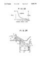
FIG. 24 is a view for illustrating the principle of the fuel control system of the present invention, and
FIG. 25 is a flow chart for illustrating another embodiment of the present invention.
DESCRIPTION OF THE PREFERRED EMBODIMENT
In FIG. 1, an engine 1 is provided with a fuel control system in accordance with an embodiment of the present and has an intake passage 2 and an exhaust passage 3. A fuel injector 4, a throttle valve 5 and an airflow meter 6 are provided in the intake passage 2, and a catalytic convertor 7 is provided in the exhaust passage 3. Further the engine 1 is provided with an engine coolant temperature sensor 8 and a crank angle sensor 9.
Output signals of the airflow meter 6, the engine coolant temperature sensor 8 and the crank angle sensor 9 are input into a control unit 10. The control unit 10 calculates the quantity of fuel to be injected from the fuel injector 4 on the basis of estimated quantities of the direct delivery part and the drawn part which are determined taking into account the period during which the intake-manifold wetting fuel on the wall surface of the intake passage 2 is permitted to vaporize before the vaporized fuel is fed to the combustion chamber as the factor which governs the degree of evaporation of the fuel. In this embodiment, the period is detected through the fuel injection timing, that is, as the fuel injection timing is advanced, the period during which the intake manifold wetting fuel on the wall surface of the intake passage 2 is permitted to vaporize is elongated and the proportion of the drawn part to the total quantity of fuel actually fed to the combustion chamber increases.
In this embodiment, a so-called divided fuel injection is employed and fuel is injected partly in the intake stroke and partly in the power stroke.
The basic control concept of the present invention will be briefly described with reference to FIG. 24 prior to detailed description of the fuel control by the control unit 10.
As shown in FIG. 24, a part F1 of fuel injected from the fuel injector 4 adheres to the wall surface of the intake passage 2 and the other part F2 of the fuel is directly introduced into the combustion chamber 1a. The part F1 which adheres to the wall surface of the intake passage 2 is referred to as "the adhering part" and the part F2 which is directly introduced into the combustion 1a is "the direct delivery part" defined before. A part F4 of fuel F3 which has adhered to the wall surface of the intake passage 2 is vaporized and is introduced into the combustion chamber 1a together with the direct delivery part F2 at each injection and the other part of the fuel F3 remains there. The former part F4 is is "the drawn part" defined before and the latter part is referred to as "the residual part". The fuel F3 which has adhered to the wall surface of the intake passage 2 is "the intake-manifold wetting fuel" defined before, and comprises the adhering part F1 of the fuel injected by the preceding injection and the residual part of the intake-manifold wetting fuel at the preceding injection. Accordingly, in order to effect the wet correction taking into account the drawn part, the quantity of the intake manifold wetting fuel on the basis of which the quantity of the drawn part is calculated must be calculated on the basis of the quantity of the adhering part of fuel injected in the preceding injection and the quantity of the residual part of the preceding adhering part. In this embodiment, calculations are effected on the basis of such a concept.
The wet correction is effected on the basis of the proportion of the direct delivery part α and the proportion of the drawn part β which are determined on experiment. In this embodiment the estimated values of the drawn part and direct delivery part are changed according to the fuel injection timing.
Now the fuel control which the control unit 10 executes will be described in detail with reference to FIGS. 2 to 4.
In the main routine shown in FIG. 2, the control unit 10 first reads the output signal Q of the airflow meter 6 in step S1 and reads the engine speed N in step S2. Then in step S3, the control unit 10 calculates the charging efficiency Ceo as detected by the airflow meter according to formula
CeO=Ka·Q/N
wherein Ka is constant. In step S4, the control unit 10 calculates the cylinder charging efficiency Ce according to the following formula.
Ce=Kc·Ce+(1-Kc)·CeO
wherein Kc is constant not smaller than 0 and smaller than 1.
In step S5, the control unit 10 calculates the flow speed Qcyl at the fuel injection valve 14 according to formula Qcyl=1/Ka·Ce·N. In step S6, the control unit 10 reads the engine cooling water temperature Tw.
Then the control unit 10 predicts the fuel injection timing and corrects the proportion of the direct delivery part and the proportion of the drawn part on the basis of the predicted fuel injection timing. (steps S7 to S15)
That is, in step S7, the control unit 10 predicts the fuel injection timing corresponding to the present operating condition of the engine based on a map (not shown) in which the fuel injection timing is related to the output Q of the airflow meter and the engine speed N. Then the control unit 10 estimates the proportion of the direct delivery part αT for the trailing injection or for the injection effected in the intake stroke (In this embodiment, divided injection method is employed.) according to the map shown in FIG. 5 in which the flow speed Qcyl at the fuel injection valve and the water temperature Tw are used as parameters. (step S8) Then the control unit 10 obtains a correction value γα corresponding to the predicted fuel injection timing according to the map shown in FIG. 9, and corrects the estimated proportion of the direct delivery part αT with the correction value γα, and employs the corrected value as the proportion of the direct delivery part αT in the subsequent control (αT ←αT ·γα)· (step S9).
Then the control unit 10 estimates the proportion of the drawn part βT for the trailing injection or for the injection effected in the intake stroke according to the map shown in FIG. 6 in which the flow speed Qcyl at the fuel injection valve and the water temperature Tw are used as parameters. (step S10) Then the control unit 10 obtains a correction value γβ corresponding to the predicted fuel injection timing according to the map shown in FIG. 10, and corrects the estimated proportion of the drawn part βT with the correction value γβ, and employs the corrected value as the proportion of the drawn part βT in the subsequent control (βT←βT·γβ). (step S11)
Then the control unit 10 estimates the proportion of the direct delivery part αL for the leading injection or for the injection effected in the power stroke according to the map shown in FIG. 7 in which the flow speed Qcyl at the fuel injection valve and the water temperature Tw are used as parameters. (step S12) Then the control unit 10 corrects the estimated proportion of the direct delivery part αL with the correction value γα, and employs the corrected value as the proportion of the direct delivery part αL in the subsequent control (αT +αL ·γα)·(step S13)
Then the control unit 10 estimates the proportion of the drawn part βL for the leading injection or for the injection effected in the power stroke according to the map shown in FIG. 8 in which the flow speed Qcyl at the fuel injection valve and the water temperature Tw are used as parameters. (step S14) Then the control unit 10 corrects the estimated proportion of the drawn part βL with the COrrection value γβ, and employs the corrected value as the proportion of the drawn part βL in the subsequent control (βL←βL·γβ)· (step S15)
The correction value γα for correcting the direct delivery parts αT and αL is increased as the fuel injection timing is retarded as shown in FIG. 9, and the correction value γβ for correcting the drawn parts βT and βL is increased as the fuel injection timing is advanced as shown in FIG. 10. This is because the later the fuel injection timing is, i.e., the wider the opening degree of the intake valve during fuel injection is, the more the direct delivery part is, and the earlier the fuel injection timing, the period before the intake valve is opened and fuel is introduced into the combustion chamber, i.e., the period during which wetting fuel vaporizes, becomes longer and the drawn part increases.
Though it is preferred that both the direct delivery part and the drawn part be corrected according to the fuel injection timing as in this embodiment, only one of them may be corrected.
Then in step S16, the control unit 10 calculates the fuel increase for warm-up Cw according to the map shown in FIG. 21 on the basis of the temperature of the cooling water Tw. In step S17, the control unit 10 calculates the basic fuel injection pulse width τa by multiplying together the fuel increase for warm-up Cw, the cylinder charging efficiency Ce which was calculated in step S4 and a fuel injection constant Kf. That is, τa=KF ·Cw·Ce
After calculating the basic fuel injection pulse width τa, the control unit 10 reads the battery voltage VB in step S18, and calculates, in step S19, an ineffective injection time for the non-divided fuel injection τV1 and that for divided fuel injection τV2 on the basis of the battery voltage VB according to the map shown in FIG. 22. In step S20, the control unit 10 calculates the dividing ratio Rinj (=the quantity of fuel to be injected by the trailing injection/the total quantity of fuel to be injected) according to the map shown in FIG. 23 on the basis of the engine speed N from.
Then in step S21, the control unit 10 determines whether the dividing ratio Rinj is not smaller than a minimum dividing ratio Krmn. The minimum dividing ratio Krmn is larger than 0 and smaller than 1. When it is determined that the dividing ratio Rinj is not smaller than a minimum dividing ratio Krmn, the control unit 10 determines whether the dividing ratio Rinj is not larger than 1 minus the minimum dividing ratio Krmn. (step S22) When it is determined in step S22 that the dividing ratio Rinj is not smaller than 1 minus the minimum dividing ratio Krmn, the control unit 10 sets a division inhibiting flag Frinh to 0. (step S23) Then in step S24, the control unit 10 sets the ineffective injection time for divided fuel injection τV2 to an ineffective injection time τV which is a practical value. The control unit 10 executes the sub routine for the leading injection shown in FIG. 3 in step S25 and executes the sub routine for the trailing injection shown in FIG. 4 in step S26.
When it is determined in step step S21 that the dividing ratio Rinj is smaller than a minimum dividing ratio Krmn, the control unit 10 nullifies the dividing ratiO Rinj in step S27, that is, the control unit 10 causes the fuel injection valve 4 to inject the total quantity of fuel to be injected solely by the leading injection. When it is determined in step S22 that the dividing ratio Rinj is smaller than 1 minus the minimum dividing ratio Krmn, the control unit 10 sets the dividing ratio Rinj to 1 in step S28, that is, the control unit 10 causes the fuel injection valve 4 to inject the total quantity of fuel to be injected solely by the trailing injection. Then the control unit 10 sets the division inhibiting flag Frinh to 1 in Step S29 and sets in step S30 the ineffective injection time for non-divided fuel injection τV1 to the ineffective injection time τV which is a practical value. Thereafter, the control unit 16 proceeds to steps S25 and S26.
The sub routine for the leading injection for a N-th cylinder will be described with reference to FIG. 3, hereinbelow.
In this sub routine, the control unit 10 determines in step S31 whether wet correction inhibiting counter Cwet is 0. When it is determined in step S30 that the wet correction inhibiting counter Cwet is 0, the control unit 10 calculates, in step S32, the wet correction injection pulse width τeN for N-th cylinder according to formula τeN=(τa-βL ·τmN)/αL, wherein τm represents the quantity of the intake-manifold wetting fuel. Otherwise, the control unit 10 sets τeN to the basic fuel injection pulse width τa in step S33.
Thereafter the control unit 10 determines in step S34 whether the division inhibiting flag Frinh is 0. When it is determined that the division inhibiting flag Frinh iS 0, the control unit 10 calculates in step S35 the leading injection pulse width τeL N on the basis of the wet correction injection pulse width τeN and the dividing ratio Rinj. Then in step S36, the control unit 10 subtracts the leading injection pulse width τeLN from the wet correction injection pulse width τeN, thereby obtaining an initial value of the trailing injection pulse width τeT N.
In Step S37, the control unit 10 determines whether the initial value of the trailing injection pulse width τeT N is not smaller than a minimum limit Ktmn of the pulse width. When it is determined in step S37 that the initial value of the trailing injection pulse width τeT N is smaller than a minimum limit Ktmn of the pulse width, the control unit 10 sets the trailing injection pulse width τeTN to the minimum limit Ktmn in step S46. Then in step S47, the control unit 10 subtracts the trailing injection pulse width τeT N from the wet correction injection pulse width τeN and sets the leading injection pulse width τeLN to the value obtained. On the other hand, when it is determined in step S37 that the initial value of the trailing injection pulse width τeTN is not smaller than a minimum limit Ktmn of the pulse width, the control unit 10 determines in step S38 whether the leading injection pulse width τeL N is not smaller than the minimum limit Ktmn of the pulse width. When it is determined that the leading injection pulse width τeL N is not smaller than the minimum limit Ktmn of the pulse width, the control unit 10 directly proceeds to step S50 and otherwise, the control unit 10 proceeds to step S50 by way of steps S48 and S49. In steps S48 and S49, the control unit 10 sets the leading injection pulse width τeL N to the minimum limit Ktmn and sets trailing injection pulse width τeT N to the value obtained by Subtracting the leading injection pulse width τeL N set in step S48 from the wet correction injection pulse width τeN. In step S50, the control unit 10 calculates the rest time past of the fuel injection valve 4 according to the following formula.
τrst=(60/N)-(τeLN+τv)
wherein τv represents the ineffective injection time.
When it is determined in step S34 that the division inhibiting flag Frinh is not 0, the control unit 10 determines in step S39 whether the dividing ratio Rinj is 0, that is, the fuel injection valve 4 is to inject the total quantity of fuel to be injected solely by the leading injection. When the answer to this question is YES, the control unit 10 sets the leading injection pulse width τeL N to the wet correction injection pulse width τeN as it is and sets the trailing injection pulse width τeT N to 0. (steps S40 and S41)
Then in step S44, the control unit 10 determines whether the leading injection pulse width τeL N is not smaller than the minimum limit Ktmn of the pulse width. When the answer to this question is YES, the control unit 10 directly proceeds to step S50. Otherwise the control unit 10 proceeds to step S50 after setting the leading injection pulse width τeL N to the minimum limit Ktmn of the pulse width in step S45.
After step S50, the control unit 10 determines in step S51 whether the rest time τrst of the fuel injection valve 4 is not smaller than a minimum limit Ktrst of the rest time. When the answer to this question is YES, the control unit 10 sets a trailing injection inhibiting flag FtinhN to 0 in step S52, and otherwise, sets in step S53 the leading injection pulse width τeL N to the the wet correction injection pulse width τeN as it is. Then control unit 10 sets the trailing injection inhibiting flag FtinhN to 1 in step S54.
Thereafter the control unit 10 resets a timer TinjN in step S55, and in step S56, the control unit 10 sets the ending time of the injection or the pulse width TendN to the value obtained by adding the ineffective injection time τv to the leading injection pulse width τeL N. Then the control unit 10 causes the fuel injection valve 4 to inject fuel in step S58 after setting an injection start signal FinjN to 1 in step S57.
When it is determined in step S30 that the dividing ratio Rinj is not 0, the control unit 10 sets the trailing injection inhibiting flag FtinhN to 0 in step S42 and sets in step S43 the trailing injection pulse width τeT N to the the wet correction injection pulse width τeN as it is.
Further, in step S59, the control unit 10 calculates an effective dividing ratio RinjN according tO formula
1-(τeLn/τeN)
and then calculates in step S60 the pulse width allotted to the leading injection τaL N in the basic injection pulse width τa according to the following formula.
τaLN=(1-R.sub.injN)·τa
Then the control unit 10 calculates in step S61 the total quantity of fuel τCLN to be fed to the cylinder by the leading injection according to the following formula.
τCLN=αL·τeLN+βL·τmN
Finally the control unit 10 calculates in step S62 the quantity of the intake manifold wetting fuel after the leading injection τmLN according to the following formula.
τm.sub.LN =(1-αL)τeLN+(1-R .sub.injN)·(1αL)τmN
The sub routine for the trailing injection for a N-th cylinder will be described with reference to FIG. 4, hereinbelow.
In step S63, the control unit 10 determines whether the quantity of fuel corresponding to the basic injection pulse width τa is not smaller than the quantity of fuel τcLN which is fed to the cylinder by the leading injection. When it is determined that the former is not smaller than the latter, the control unit 10 determines in step S64 whether wet correction inhibiting counter Cwet is 0. When it is determined in step S64 that the wet correction inhibiting counter Cwet is 0, the control unit 10 determines in step S65 whether trailing injection inhibiting flag FtinhN is 0. When it is determined that - the trailing injection inhibiting flag FtinhN is 0, the control unt 10 calculates the wet correction injection pulse width τeN for N-th cylinder according to the following formula in step S66.
τeN=(τα-β.sub.T ·τmN)·/α.sub.T
In the next step S67, the control unit 10 calculates the trailing injection pulse width τeT N in the divided injection according to the following formula.
τeTN=(τa-τaLN-R.sub.injN ·βT ·τmN)/αT
wherein τaL N represents the pulse width allotted to the leading injection τaL N and RinjN represents the effective dividing ratio RinjN.
Thereafter, the control unit 10 determines in step S70 whether the division inhibiting flag Frinh is 0. When it is determined that the division inhibiting flag Frinh is 0, the control unit 10 determines in step S71 whether the trailing injection pulse width τeT N is not smaller than a minimum limit Ktmn of the pulse width. When it is determined in step S71 that the trailing injection pulse width τeT N is not smaller than a minimum limit Ktmn of the pulse width, the control unit 10 calculates the rest time τrst of the fuel injection valve 4 according to the following formula.
τrst=(60/N)-(τeTN+τV)
wherein τv represents the ineffective injection time.
In step S81, the control unit 10 determines whether the rest time τrst of the fuel injection valve 4 is not smaller than a minimum limit Ktrst of the rest time. When the answer to this question is NO, the control unit 10 calculates in step S82 the trailing injection pulse width τeT N according to formula
τeTN=(60/N)-(Ktrst+τv),
and then proceeds to step S83. Otherwise, the control unit 10 directly proceeds to step S83.
In step S83, the control unit 10 resets a timer TinjN, and in Step S84, the control unit 10 sets the ending time of the injection or the pulse width TendN to the value obtained by adding the ineffective injection time τv to the trailing injection pulse width τeT N. Then the control unit 10 causes the fuel injection valve 4 to inject fuel in step S87 after setting an injection start signal FinjN to 1 in step S86.
Finally the control unit 10 calculates in step S89 the total quantity of the intake-manifold wetting fuel τmN according to the following formula.
τmN=(-αT)τeTN+R.sub.injN ·(1-βT)·τmN+τmLN
When the answer to the question in step S63 is NO, the control unit 10 proceeds to step S89.
When the answer to the question in step S64 is NO, that is, when the wet correction is not to be made, the control unit 10 sets τeN to the basic fuel injection pulse width τa in step S72. Thereafter the control unit 10 determines in step S73 whether the trailing injection inhibiting flag FtinhN is 0. When it is determined that the trailing injection inhibiting flag FtinhN is 0, the control unit 10 subtracts the leading injection pulse width τaL N from the basic injection pulse width τa, and sets the trailing injection pulse width τeTN to the difference. (step S74) Thereafter the control unit 10 proceeds to step S70.
When the answer to the question in step S65 is NO, that is, when the trailing injection is inhibited, the control unit 10 calculates in step S68 the wet correction injection pulse width τeN according to the following formula.
τeN=τα-βL·mN
Then in step S69, the control unit 10 sets the leading injection pulse width τeL N to the wet correction injection pulse width τeN obtained in step S68, and sets the trailing injection pulse width τeT N to 0. In step S85, the control unit 10 sets the ending time of the injection or the pulse width TendN to the value obtained by adding the ineffective injection time rv to the leading injection pulse width τeL N. Then the control unit 10 proceeds to step S89 after extending the leading injection time in step S88.
When it is determined in step S70 that the division inhibiting flag Frinh is not 0, that is, when the divided injection is not to be effected, the control unit 10 determines in step S75 whether the dividing ratio Rinj is 1, that is, which is to be effected the leading injection or the trailing injection. When it is determined that the dividing ratio Rinj is 1, the control unit 10 determines in step S76 whether the wet correction injection pulse width τeN is not smaller than the minimum limit Ktmn of the pulse width. When it is determined that the wet correction injection pulse width τeN is not smaller than the minimum limit Ktmn of the pulse width, the control unit 10 sets in step S78 the trailing injection pulse width τeT N to the wet correction injection pulse width τeN and then proceeds to step S80. Otherwise, the control unit 10 sets in step S77 the trailing injection pulse width τeT N to the minimum limit Ktmn of the pulse width and then proceeds to step S80.
When the answer to the question in step S71 is NO, the control unit 10 proceeds to step S80 after executing step S77.
Though, in the embodiment described above, the estimated values of the drawn part and direct delivery part are changed according to the fuel injection timing, i.e., the length of the period during which the fuel vaporizes, they may be changed according to other factors as described above.
FIG. 11 shows an example of the correction value γα in the case where the direct delivery parts αT and αL are corrected according to the temperature of fuel, and FIG. 12 shows an example of the correction value γβ in the case where the drawn parts βT and βL are corrected according to the temperature of fuel. In this case, the correction value γα for the direct delivery part is increased with increase in the fuel temperature at a rate higher than the correction value γβ for the drawn part. This is because the fuel comes to vaporize better with increase in the fuel temperature and the proportion of the intake-manifold wetting fuel is reduced.
FIG. 13 shows an example of the correction value γα in the case where the direct delivery parts αT and αL are corrected according to the fuel pressure, and FIG. 14 shows an example of the correction value γβ in the case where the drawn parts βT and βL are corrected according to the fuel pressure. In this case, though the correction value γα for the direct delivery part is reduced with increase in the fuel pressure, the correction value γβ for the drawn part is kept constant irrespective of the fuel pressure as can be understood from FIGS. 13 and 14. This is because as the fuel pressure increases, the fuel injected from the injector 4 becomes more apt to adhere to the wall surface of the intake passage 2 and the proportion of the direct delivery part is reduced, whereas the proportion of the drawn part is hardly affected by the fuel pressure per se.
FIG. 15 shows an example of the correction value γα in the case where the direct delivery parts αT and αL are corrected according to the temperature of intake air, and FIG. 16 shows an example of the correction value γβ in the case where the drawn part βT and βL are corrected according to the temperature of intake air. In this case, the correction values γα and γβ are both gradually increased with increase in the temperature of intake air. This is because the fuel comes to vaporize better with increase in the temperature of intake air.
FIG. 17 shows an example of the correction value γα in the case where the direct delivery parts αT and αL are corrected according to the atmospheric pressure, and FIG. 18 shows an example of the correction value γβ in the case where the drawn part βT and βL are corrected according to the atmospheric pressure. In this case, the correction values γα and γβ are both gradually reduced with increase in the atmospheric pressure. This is because the fuel comes to vaporize better with decrease in the atmospheric pressure.
FIG. 19 shows an example of the correction value γα in the case where the direct delivery parts αT and αL are corrected according to both the quantity of the intake-manifold wetting fuel and the temperature of intake air, and FIG. 20 shows an example of the correction value γβ in the case where the drawn parts βT and βL are corrected according to both the quantity of the intake-manifold wetting fuel and the temperature of intake air. In this case, the correction value γα is never smaller than 1.0 and is increased with increase in the quantity of the intake-mainfold wetting fuel and with increase in the temperature of intake air. This is because as the quantity of the intake-manifold wetting fuel increases, the wall surface of the intake passage 2 is more smoothed and more part of the injected fuel is directly fed to the combustion chamber and because the fuel comes to vaporize better with increase in the temperature of intake air. The correction value γβ is also increased with increase in the quantity of the intake-manifold wetting fuel and with increase in the temperature of intake air for substantially the same reason, but in the range where the quantity of the intake-manifold wetting fuel is small, the correction value γβ is smaller than 1.0. This is, because when the quantity of the intake-manifold wetting fuel is small, a part of the intake-manifold wetting fuel enters the recesses and contact of the fuel in the recesses with airflow passing through the intake passage becomes worse and the degree of evaporation is lowered.
When the engine is started up, fuel is generally increased to facilitate start of the engine and at the same time and the quantity of the intake-manifold wetting fuel is very small. Accordingly, estimation of the direct delivery part and the drawn part is very difficult and it is preferred that the wet correction be not effected for a predetermined time after the engine is started. FIG. 25 shows a sub routine for inhibiting the wet correction until the engine speed reaches a predetermined value.
The control unit 10 first determines whether the operating condition of the engine is in the starting zone in which, for instance, the engine speed N is lower than 500rpm. (step S91) When it is determined that the operating condition of the engine is in the starting zone, the control unit 10 sets wet correction flag Xwet to 0 in order to inhibit the wet correction and keeps the flag Xwet at 0 until the engine speed N reaches a predetermined value Np (e.g., 1200rpm). (steps S92 and S93) When the engine speed N reaches the predetermined value for the first time, the control unit 10 sets an initial value of the wet correction pulse width τm according to the following formula.
τm=(1-α)·τa/β
This formula is derived from formula τe=(τa-β·τm)/α
(wherein τe represents fuel injection pulse width to be actually output) by substituting τa for τe on the presumption that there is no intake-manifold wetting fuel. Thereafter, the control unit 10 sets the wet correction pulse width τna according to the following formula.
τm=τa·(1-α)+τm(i-1)·β
wherein τm(i-1) is the preceding value of τm. (steps S95 to S97)