US5105059A - Environmentally sealed switch construction - Google Patents
Environmentally sealed switch construction Download PDFInfo
- Publication number
- US5105059A US5105059A US07/668,297 US66829791A US5105059A US 5105059 A US5105059 A US 5105059A US 66829791 A US66829791 A US 66829791A US 5105059 A US5105059 A US 5105059A
- Authority
- US
- United States
- Prior art keywords
- combination according
- mounting bracket
- switch
- lamp
- actuator
- Prior art date
- Legal status (The legal status is an assumption and is not a legal conclusion. Google has not performed a legal analysis and makes no representation as to the accuracy of the status listed.)
- Expired - Lifetime
Links
Images


Classifications
-
- H—ELECTRICITY
- H01—ELECTRIC ELEMENTS
- H01H—ELECTRIC SWITCHES; RELAYS; SELECTORS; EMERGENCY PROTECTIVE DEVICES
- H01H23/00—Tumbler or rocker switches, i.e. switches characterised by being operated by rocking an operating member in the form of a rocker button
- H01H23/02—Details
- H01H23/04—Cases; Covers
- H01H23/06—Dustproof, splashproof, drip-proof, waterproof, or flameproof casings
-
- H—ELECTRICITY
- H01—ELECTRIC ELEMENTS
- H01H—ELECTRIC SWITCHES; RELAYS; SELECTORS; EMERGENCY PROTECTIVE DEVICES
- H01H23/00—Tumbler or rocker switches, i.e. switches characterised by being operated by rocking an operating member in the form of a rocker button
- H01H23/02—Details
- H01H23/025—Light-emitting indicators
-
- H—ELECTRICITY
- H01—ELECTRIC ELEMENTS
- H01H—ELECTRIC SWITCHES; RELAYS; SELECTORS; EMERGENCY PROTECTIVE DEVICES
- H01H23/00—Tumbler or rocker switches, i.e. switches characterised by being operated by rocking an operating member in the form of a rocker button
- H01H23/003—Tumbler or rocker switches, i.e. switches characterised by being operated by rocking an operating member in the form of a rocker button with more than one electrically distinguishable condition in one or both positions
-
- H—ELECTRICITY
- H01—ELECTRIC ELEMENTS
- H01H—ELECTRIC SWITCHES; RELAYS; SELECTORS; EMERGENCY PROTECTIVE DEVICES
- H01H23/00—Tumbler or rocker switches, i.e. switches characterised by being operated by rocking an operating member in the form of a rocker button
- H01H23/02—Details
- H01H23/12—Movable parts; Contacts mounted thereon
- H01H23/16—Driving mechanisms
- H01H23/166—Driving mechanisms with positive action
-
- H—ELECTRICITY
- H01—ELECTRIC ELEMENTS
- H01H—ELECTRIC SWITCHES; RELAYS; SELECTORS; EMERGENCY PROTECTIVE DEVICES
- H01H3/00—Mechanisms for operating contacts
- H01H3/001—Means for preventing or breaking contact-welding
-
- Y—GENERAL TAGGING OF NEW TECHNOLOGICAL DEVELOPMENTS; GENERAL TAGGING OF CROSS-SECTIONAL TECHNOLOGIES SPANNING OVER SEVERAL SECTIONS OF THE IPC; TECHNICAL SUBJECTS COVERED BY FORMER USPC CROSS-REFERENCE ART COLLECTIONS [XRACs] AND DIGESTS
- Y10—TECHNICAL SUBJECTS COVERED BY FORMER USPC
- Y10S—TECHNICAL SUBJECTS COVERED BY FORMER USPC CROSS-REFERENCE ART COLLECTIONS [XRACs] AND DIGESTS
- Y10S200/00—Electricity: circuit makers and breakers
- Y10S200/42—Contact welding considerations
Definitions
- a switch housing or case is provided in two parts, one a base having a bottom wall in which openings are provided for terminals that define fixed contacts within the case cavity.
- the case also has laterally spaced front and rear walls as well as opposed end walls all integrally connected to the bottom wall and to each other. At least one movable contact is provided in the switch cavity.
- the switch case or housing also includes a mounting bracket having a top wall and laterally spaced front and rear walls adapted to mate with the front and rear walls of the base.
- the bracket also has opposed end walls integrally connected to the front and rear walls thereof to define a downwardly open cavity that communicates with the cavity in the base to define the enclosed switch chamber or cavity.
- the mounting bracket top wall defines a raised center rib portion which in turn defines laterally spaced sockets inside the switch cavity to receive upper shoulder portions of an actuator.
- the actuator has at least one downwardly biased plunger slidably received in a plunger cavity of the actuator and the lower end of the plunger engages the movable contact to pivot the movable contact in response to actuator movement on a laterally extending axis defined by these actuator shoulders and associated sockets.
- a manually movable means preferably in the form of a rocker is provided above the mounting bracket top wall and transfers pivoting movement to the actuator by means of a rod extending into a central hole in the top of the mounting bracket generally between the shoulder receiving sockets in the rib.
- one or two lamps is supported in one or two openings in the mounting bracket top wall.
- the laterally spaced front and rear walls of the mounting bracket define downwardly open slots for receiving lamp leads, which leads would be connected to fixed terminals located on ides of the switch case opposite from the lamp, and which leads are electrically connected to said terminals by coil compression springs compressed between the terminals and lamp leads within cavities defined in part by the end walls of the switch case base and mounting bracket.
- the rocker or manual means for operating the switch has a depending post provided centrally of the rocker and received in an upwardly open recess provided for said post in the actuator.
- Laterally spaced pivot posts are provided at opposite ends of the central rib of the mounting bracket and are received in openings provided for them in depending walls of the rocker or similar operating means, spaced inwardly of the side walls or skirts of the rocker itself.
- Still other depending walls of the rocker are adapted to engage the upstanding rib portion of the mounting bracket to further define and strengthen the pivot for the rocker so that the rocker and actuator move on the same pivot axis in the switch case.
- the rocker is so designed to snap easily and securely onto the switch bracket while allowing easy removal with a simple removal tool. The easy rocker installation and removal allows later customer replacement or exchange of rockers without impairing the integrity of the switch sealing.
- a snap-on connector plug to house terminal connectors may be provided.
- a depending orientation pin is provided on the switch base and is adapted to be received in a corresponding opening provided for this purpose in the plug.
- the plug also has a resiliently deformable upstanding leg with a latching ledge that is received in a notch in the switch base whereby the ledge locks behind an edge of the bracket which is secured to the switch base.
- the connector plug is adapted to house a variety of conventional female connectors, each of which is crimped to a wire conductor and is then nested within the connector plug so as to receive a terminal projecting from the switch base.
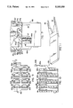
- FIG. 1 is a vertical section taken through a switch constructed in accordance with the present invention, the rocker and actuator and movable contact being shown in one position.
- FIG. 2 is a vertical section taken generally on line A--A of FIG. 1, but with the actuator shown in a position intermediate of its two extreme end positions, that is with the plungers aligned with the center fixed contacts of which two different versions are shown.
- FIGS. 2A and 2B are sectional views through the composite rocker.
- FIG. 3 is a top plan view of the bracket.
- FIG. 4 is a vertical section of the bracket taken generally on the line B--B of FIG. 3.
- FIG. 5 is a top plan view of the bracket with a cutaway sectioning of the bracket top surface to reveal details of the bracket struts and mounting wings.
- FIG. 6 is a vertical section of the bracket taken generally on the line C--C of FIG. 3.
- FIG. 7 is a vertical section though an alternative switch illustrating a connector plug attached to the bottom of the switch base.
- FIG. 8 is an end view of the switch illustrating the attachment of the connector plug to the switch base.
- FIG. 9 is a top plan view of the connector plug.
- FIG. 10 is a vertical section through the connector generally on the line D--D of FIG. 9.
- FIG. 11 is a diagonal view of the rocker removal tool.
- FIG. 1 shows an electric switch case constructed in accordance with the present invention, and the invention will be described with reference to the orientation of the switch as depicted in these drawings with the understanding that the terms upwardly and downwardly are relative when interpreting the scope of the claims as presented hereinafter.
- the switch shown is equipped with a lamp 10, which lamp has associated conductors 10a and 10b adapted to be electrically connected respectively to fixed terminals 39 and 36 of the switch.
- the lamp 10 may be in the form of a neon incandescent, or light-emitting diode (LED). With the use of an LED or neon lamp a resistor 16 may be provided in the lamp circuit. Coil compression springs such as indicated at 18 and 20 would be provided between the lamp leads 10a and 10b and the terminals 39 and 36 in order to make contact between the lamp and terminals and allow the option of installing a resistor 16 in the lamp circuit.
- the electric switch case or housing comprises an upwardly open base 22 having a bottom wall 22b in which openings are provided for various fixed terminals such as 36, 37, 38 and 39.
- the switch base 22 also includes laterally spaced front and rear walls 22c and 22d, FIG. 2, and opposed end walls 22e and 22f, FIG. 1, all of which upstanding walls are integrally connected to one another and to the bottom wall 22b so as to define an upwardly open cavity that cooperates with a downwardly open cavity, defined by the mounting bracket 24, to provide an enclosed cavity for the switch components.
- the mounting bracket 24 includes front and rear walls 24c and 24d which are adapted to mate with the front and rear walls 22c and 22d, respectively, of the base 22 as indicated generally at 23c and 23d in FIG. 2.
- the mounting bracket 24 also includes end walls 24e and 24f which mate with the end walls 22e and 22f, respectively, as indicated generally at 23e and 23f in FIG. 1. This geometry effectively seals the interior of the switch case cavity from external environmental hazards.
- top wall 24b defines a peripherally extending flange 24a, which flange is adapted to engage the outer face of a panel that defines an opening of suitable rectangular shape for receiving the switch case.
- this top wall surface 24b of the mounting bracket 24 has a central laterally extending rib portion 24g, illustrated at least in part in FIG. 2 and also shown in FIG. 4.
- An upstanding boss 24h is defined centrally of the top wall 24b, and forms the center portion of the rib 24g.
- the ribs 24g define inner sockets 24j, FIG. 4, that receive shoulder portions 28a, FIG. 2, of an actuator 28 provided inside the switch case and adapted to move pivotally between the limit stops 24k illustrated in FIG. 1.
- laterally opposed outwardly projecting axle defining posts 24i serve to lock into openings created in resilient wall portions 26a of the rocker 26.
- the rocker is of two part construction 26/27, whereby the first part 26 is molded with resilient wings 26a. Slots 26s, FIG. 2, in the first part 26 receive depending skirts 27a defined by the second part material. These skirts 27a extend to the edge 26b of the resilient wings 26a which engage the bracket posts 24i.
- the first part 26 of the rocker is of a hard plastic and provides the structural form and strength of the rocker, thereby allowing the second overlay material, 27, to be molded of either a soft pliable material or a hard material, as desired.
- the second overlay material, 27, is molded over the top and side surface of the rocker with the underside of the rocker defined by the first part 26, except for the skirts 27a that fills the slots 26a through the top surface of the first part, 26, and extend down to the edge 26b of the resilient wings 26a.
- This skirt material 27a flexes outward with the resilient wings 26a as the rocker is forced onto the bracket posts 24i, and the wings 26a snap back to engage the posts 24i with the edges 26b.
- the skirt material 27a remains flexed outward.
- the rocker also includes inner walls 26c with an inverted U-shaped bottom edge which provides a stop limit when the rocker is snapped onto bracket posts 24i, and which provides a recess to pivot upon the external U-shaped top surface 24v, FIGS. 2 and 4, of the ribs 24g. These walls 26c also prevent damaging downward or twisting pressure exerted upon the rocker from being transmitted to locking posts 24i.
- the rocker may be easily removed from the bracket with the use of a tool with two tapered probes 33, FIG. 11, which would be inserted from either end of the switch, between the rocker 26 and the flange 24a, FIG. 1, whereby the pointed ends of the probes would enter the gaps 26x between the resilient wings 26a and the bracket rib ends 24x.
- the expanding width of the probes causes the wings 26a to flex outward, ultimately forcing the surfaces 26b to unlatch from the posts 24i and the rocker to move upward off the bracket. Due to the angled inner surfaces of the wings 26a, the wings 26a will be forced upward by the probe as well as outward.
- the first part of the rocker may be of translucent or transparent material and the second overly material 27 may be opaque and molded so as to leave a portion of the translucent material uncovered to provide illumination by a lamp located beneath the uncovered area 26d, FIG. 1.
- the actuator 28, FIG. 2 defines a central opening 28b which serves to receive a depending post 26c of complementary shape provided for it centrally of the rocker 26.
- the rocker and actuator move together about a laterally extending axis defined by the axle defining posts 24i of the mounting bracket top wall rib portion.
- the upper edge of the shoulders 28a of the actuator cooperate with the sockets 24j defined by the mounting bracket so that the actuator always moves on the same axis as that defined for the rocker.
- At least one spring biased plunger 30 is provided in a downwardly open plunger recess or cavity, and the lower end of the plunger engages a movable contact element which is pivotally received in the upper end of the central fixed contact 13 referred to previously.
- a movable contact element which is pivotally received in the upper end of the central fixed contact 13 referred to previously.
- the switch case comprises two half sections, one the lower base which supports the terminals and fixed and movable contacts inside the switch cavity, and the other part comprising a mounting bracket which mates with the base and defines the top wall of the switch case cavity.
- the geometric fit of the base to the bracket effectively seals the sides of the switch case cavity from external environmental hazards.
- the central boss 24h of the mounting bracket is so configured as to receive means connecting or coupling the rocker to the actuator.
- Such means preferably comprises a raised center portion of the actuator that in turn defines a central opening 28b for receiving the depending post 26c on the rocker.
- An O-ring 29 is preferably provided in the gap between the boss on the center portion of the mounting bracket top wall and the raised portion of the actuator as best shown in FIGS. 1 and 2.
- the post 26c on the rocker is of a lesser diameter that the opening 28b in the actuator to allow an amount of non-binding movement of the post into and out of the opening 28b.
- This clearance allows pivoting movement to be transferred from the rocker to the actuator, yet prevents the transfer of pressure which may force the actuator into the switch housing and compromise the seal provided by the spring biased plunger 30 exerting pressure through the raised center portion of the actuator and compressing the O-ring 29 against the bracket boss 24h.
- the upper edge of the shoulders 28a of the actuator cooperate with the angled sockets 24j of the mounting bracket so that the space provided for the O-ring seal is maintained constant during actuation, thereby allowing consistent compression of the O-ring, maximizing the sealing effectiveness and minimizing wear of the O-ring.
- the actuator shoulders 28a engagement with the angled sockets 24j provide stability to the actuator when only one spring biased plunger 30 is employed.
- each end wall 24e and 24f defines a central strut 24n, which strut has laterally outwardly projecting wings 24m that have stepped ridges for cooperating with the underside of the mounting panel opening edge to secure the switch case in the mounting panel.
- These struts 24n are designed to permit assembly of the mounting bracket to the switch case in only one orientation. This result is achieved by providing ribs 24p and 24r of different size on these struts 24n.
- the ribs 24p and 24, respectively, are adapted to be received only in appropriately sized slots of corresponding geometry in the end walls 22e and 22f of the switch case base 22.
- the front and rear walls 24c and 24d respectively have inner surfaces which include inwardly projecting portions 24k which serve as stops for pivotal movement of the actuator, and which also serve to cooperate with the walls 24c and 24d to define downwardly open slots 24t that are adapted to receive a lead line 10a of the lamp 10 and to prevent the lead line 10a from interfering with the motion of the actuator 28 in the switch case as described above.
- the lamp 10 is conveniently mounted in the mounting bracket 24 as referred to previously, and two circumaxially spaced feet 24y, FIGS. 1 and 3, support the lamp 10 in a position where light from the lamp can emanate through a transparent window portion 26d defined for this purpose in the rocker 26/27.
- the external configuration of the rocker 26/27 is preferably such that its ends 27y are adapted to extend over the flange 24a of the mounting bracket.
- the rocker has outer skirts 27x that are not used to pivotally support the rocker and therefor do not have the usual openings provided in prior art rockers for this purpose.
- the rocker as so designed provides a low profile, clean design above a mounting panel while shielding the O-ring actuator seal and, if employed, the O-ring lamp seal(s) from top surface environmental elements.
- the area between the lamp and the bracket would be preferably sealed with an O-ring 11, FIG. 1.
- the O-ring would be inserted from above the lamp and compress into the area between the lamp and bracket with a stop provided by the ledge 24s.
- the switch may be provided with two lamps as allowed for in the bracket in FIG. 3, or with one lamp as shown in FIG. 1 with the second lamp area molded closed, or with no lamp in which case both lamp areas would be molded closed.
- the lamp mounting arrangement is designed to receive either neon, incandescent, or LED type lamps.
- the diametrically opposed depending leg portions 24y, FIGS. 3, 4, and of the bracket are adapted to flex outwardly to maintain pressure against and hold in place a neon or incandescent bulb.
- the legs 24y, FIG. 6, have notches 24w configured to snap over the bottom circumferential ridge of a light-emitting-diode, LED, and lock such a diode securely in place when used as a lamp.
- the feet have angled edges 24z at top and bottom to allow insertion of a lamp from either direction.
- this component of the assembly is held i place by means of an upwardly extending resilient arm 150a having a free end portion defining a latching edge 150b that is adapted to be received in a suitable notch 22s defined for this purpose in the switch case base 22.
- the latching edge 150b snaps over an edge 24q of the bracket extending from the struts 24h.
- the extension edges 24q from the struts 24n also provide a surface which latches against protrusions 22q of the base 22, thereby securing the bracket in the base.
- the connector plug 150 also defines an upwardly open bore 150p, FIGS. 7 and 9, for receiving a locating pin 22p defined for this purpose in the bottom wall of the switch case 22.
- the plug 150 serves to electrically connect any depending terminals such as 46, 47, and 49, FIG. 7, to conductive female terminals (not shown) provided in the plug itself.
- the plug 150 has relatively large openings or receptacles 150d-150g. These openings are designed to receive a variety of conventional spring type female connectors which lock within the connector plug after being secured to the end of a conductive wire. These female connectors are adapted to be received in the cavities 150d, 150e, 150f, 150g, 150h, 150i, 150k, FIG. 9, in such a way to accept terminals extending from the switch base, such as terminals 46, 47, and 49. Once the female connectors have been inserted into the receptacles provided for them in the plug 150, they become locked securely in place as a result of the shape of these receptacles and a barb commonly furnished on this type of female connector.
- FIG. 9 shows the plug 150 in top plan view with the switch's optional spade terminals 46 through 49, and 36 through 39 being illustrated in broken lines.
- the female connectors or terminal ends are not shown in the views FIGS. 9 and 10 because they are of conventional configuration and of standard size for a particular size spade terminal of the type illustrated as 37 and 47, on the switch case base of FIG. 2.
- FIG. 7 is different from that illustrated in FIG. 1. As indicated previously with reference to the description of FIG. 2, these differently configured movable contacts are adapted to be supported on differently configured center fixed contacts. It will be apparent that a typical double pole switch may include identical movable contacts and center fixed contacts of either of the two varieties illustrated in the drawings.
Abstract
Description
Claims (19)
Priority Applications (1)
| Application Number | Priority Date | Filing Date | Title |
|---|---|---|---|
| US07/668,297 US5105059A (en) | 1991-03-14 | 1991-03-14 | Environmentally sealed switch construction |
Applications Claiming Priority (1)
| Application Number | Priority Date | Filing Date | Title |
|---|---|---|---|
| US07/668,297 US5105059A (en) | 1991-03-14 | 1991-03-14 | Environmentally sealed switch construction |
Publications (1)
| Publication Number | Publication Date |
|---|---|
| US5105059A true US5105059A (en) | 1992-04-14 |
Family
ID=24681784
Family Applications (1)
| Application Number | Title | Priority Date | Filing Date |
|---|---|---|---|
| US07/668,297 Expired - Lifetime US5105059A (en) | 1991-03-14 | 1991-03-14 | Environmentally sealed switch construction |
Country Status (1)
| Country | Link |
|---|---|
| US (1) | US5105059A (en) |
Cited By (25)
| Publication number | Priority date | Publication date | Assignee | Title |
|---|---|---|---|---|
| US5343007A (en) * | 1992-05-12 | 1994-08-30 | Otto Engineering, Inc. | Rocker switch |
| US5436421A (en) * | 1994-04-13 | 1995-07-25 | Carlingswitch, Inc. | Progressive switch |
| DE19541380A1 (en) * | 1995-11-07 | 1997-05-15 | Teves Gmbh Alfred | Switches with switch modules snapped onto the circuit board |
| US5725087A (en) * | 1996-10-07 | 1998-03-10 | Carlingswitch, Inc. | Rotary switch that converts to rotary action, a toggle style switching mechanism |
| US5819912A (en) * | 1995-01-31 | 1998-10-13 | Itw Switches Asia Ltd. | Slide selector switch and inlet outlet device |
| US5924552A (en) * | 1997-08-04 | 1999-07-20 | Yu; Tsung-Mou | Retainer structure of switch |
| US5970607A (en) * | 1993-09-30 | 1999-10-26 | Illinois Tool Works Inc. | Method of making an electrical subassembly |
| US6008458A (en) * | 1998-03-30 | 1999-12-28 | C & K Components, Inc. | Sealed slide switch |
| US6013885A (en) * | 1999-01-21 | 2000-01-11 | Carlingswitch, Inc. | Rocker switch with lamp module |
| US6444930B1 (en) | 2001-03-07 | 2002-09-03 | Carling Technologies | Environmentally sealed rocker switch |
| US6570114B1 (en) | 2001-11-05 | 2003-05-27 | Reliance Controls Corporation | Center contact and rocker arrangement for a single pole double-throw switch |
| US6590175B1 (en) * | 2002-06-03 | 2003-07-08 | Defond Manufacturing Limited | Illuminated rocker switch with resistor |
| US6596956B1 (en) | 2001-11-05 | 2003-07-22 | Reliance Controls Corporation | SPDT switch with multiple contact arrangement |
| US6600122B1 (en) | 2001-11-05 | 2003-07-29 | Reliance Controls Corporation | Centering arrangement for a movable contact member in a rocker-type switch |
| EP1593806A1 (en) * | 2004-05-07 | 2005-11-09 | Kabushiki Kaisha Tokai Rika Denki Seisakusho | Swinging switch device |
| US20060011460A1 (en) * | 2004-07-15 | 2006-01-19 | Yung-Ching Hung | Switch structure |
| US7009128B1 (en) | 2004-01-12 | 2006-03-07 | Reliance Controls Corporation | Side contact rocker-type switch assembly |
| US20060081454A1 (en) * | 2004-10-14 | 2006-04-20 | Richard Sorenson | Electrical switch rocker and assembly |
| US20060163052A1 (en) * | 2005-01-27 | 2006-07-27 | Alps Electric Co., Ltd. | Switch device having operation member which is not easily disengaged from housing even when large amount of load is applied |
| US20060245683A1 (en) * | 2005-04-25 | 2006-11-02 | Bateman David E | Switching Device and Method |
| US20080135390A1 (en) * | 2006-11-10 | 2008-06-12 | Siemens Energy & Automation, Inc. | Lighting control module contact arm & armature plate |
| US20080283376A1 (en) * | 2007-05-14 | 2008-11-20 | Lamb Justin J | Electrical switches |
| US20100258418A1 (en) * | 2009-04-08 | 2010-10-14 | Tsung Mou Yu | Switch Assembly Having Indicator |
| US20140187072A1 (en) * | 2011-08-11 | 2014-07-03 | Ntt Facilities, Inc. | Connector |
| CN103971975A (en) * | 2013-01-31 | 2014-08-06 | 上海永星电子开关有限公司 | Double-pole separate-shell waterproof rocker switch |
Citations (21)
| Publication number | Priority date | Publication date | Assignee | Title |
|---|---|---|---|---|
| DE1236627B (en) * | 1960-03-23 | 1967-03-16 | Paul Hochkoepper & Co Elektrot | Cover for waterproof rocker or toggle switch |
| DE1490910A1 (en) * | 1964-11-26 | 1969-06-19 | Vedder Gmbh Geb | Switches with permanent or control lighting |
| US4013857A (en) * | 1974-06-12 | 1977-03-22 | Nihon Kaiheiki Industrial Company, Ltd. | Illumination-type small-sized switch |
| US4087669A (en) * | 1975-03-05 | 1978-05-02 | Siemens Aktiengesellschaft | Housed electrical switch with slide fastening members |
| US4121071A (en) * | 1977-02-17 | 1978-10-17 | Stackpole Components Company | Electric switch |
| US4218602A (en) * | 1979-03-06 | 1980-08-19 | Eaton Corporation | Sealed electric switch |
| US4242551A (en) * | 1979-05-14 | 1980-12-30 | Carlingswitch, Inc. | Environmentally sealed rocker switch |
| US4268734A (en) * | 1979-07-30 | 1981-05-19 | Carlingswitch, Inc. | Environmentally sealed toggle switch |
| DE3011184A1 (en) * | 1980-03-22 | 1981-10-15 | SWF-Spezialfabrik für Autozubehör Gustav Rau GmbH, 7120 Bietigheim-Bissingen | Module for motor vehicle - has switch and plug casing fitting easily onto holder, maintaining pleasing appearance |
| US4321443A (en) * | 1980-08-25 | 1982-03-23 | Eaton Corporation | Lighted toggle lever switch having articulated conductors |
| US4340791A (en) * | 1979-05-14 | 1982-07-20 | Carlingswitch, Inc. | Environmentally sealed rocker switch |
| US4347417A (en) * | 1981-02-11 | 1982-08-31 | Carlingswitch, Inc. | Switch construction |
| US4352965A (en) * | 1980-09-29 | 1982-10-05 | Carlingswitch, Inc. | Toggle switch assembly |
| US4382154A (en) * | 1979-12-03 | 1983-05-03 | Agence Nationale De Valorisation De La Recherche (Anvar) | Device sensitive to a temperature gradient and its application for constructing a thermal fluxmeter or solar sensor |
| US4418254A (en) * | 1982-04-16 | 1983-11-29 | Eaton Corporation | One piece operator for electric switch having pivoting and sliding contactor |
| US4454400A (en) * | 1981-12-09 | 1984-06-12 | Carlingswitch, Inc. | Switch construction |
| US4480159A (en) * | 1982-01-07 | 1984-10-30 | Alco Electronic Products, Inc. | Sub-miniature three position switch with built-in lever lock |
| US4532393A (en) * | 1982-07-30 | 1985-07-30 | Omron Tateisi Electronics, Co. | Push button switch |
| US4758724A (en) * | 1985-05-03 | 1988-07-19 | Mcgill Manufacturing Co., Inc. | Panel mounted toggle switch |
| US4789766A (en) * | 1987-11-24 | 1988-12-06 | Tower Manufacturing Corporation | Water-resistant switch construction |
| GB2213649A (en) * | 1985-03-01 | 1989-08-16 | Ashley Accessories Ltd | Switch rockers |
-
1991
- 1991-03-14 US US07/668,297 patent/US5105059A/en not_active Expired - Lifetime
Patent Citations (21)
| Publication number | Priority date | Publication date | Assignee | Title |
|---|---|---|---|---|
| DE1236627B (en) * | 1960-03-23 | 1967-03-16 | Paul Hochkoepper & Co Elektrot | Cover for waterproof rocker or toggle switch |
| DE1490910A1 (en) * | 1964-11-26 | 1969-06-19 | Vedder Gmbh Geb | Switches with permanent or control lighting |
| US4013857A (en) * | 1974-06-12 | 1977-03-22 | Nihon Kaiheiki Industrial Company, Ltd. | Illumination-type small-sized switch |
| US4087669A (en) * | 1975-03-05 | 1978-05-02 | Siemens Aktiengesellschaft | Housed electrical switch with slide fastening members |
| US4121071A (en) * | 1977-02-17 | 1978-10-17 | Stackpole Components Company | Electric switch |
| US4218602A (en) * | 1979-03-06 | 1980-08-19 | Eaton Corporation | Sealed electric switch |
| US4340791A (en) * | 1979-05-14 | 1982-07-20 | Carlingswitch, Inc. | Environmentally sealed rocker switch |
| US4242551A (en) * | 1979-05-14 | 1980-12-30 | Carlingswitch, Inc. | Environmentally sealed rocker switch |
| US4268734A (en) * | 1979-07-30 | 1981-05-19 | Carlingswitch, Inc. | Environmentally sealed toggle switch |
| US4382154A (en) * | 1979-12-03 | 1983-05-03 | Agence Nationale De Valorisation De La Recherche (Anvar) | Device sensitive to a temperature gradient and its application for constructing a thermal fluxmeter or solar sensor |
| DE3011184A1 (en) * | 1980-03-22 | 1981-10-15 | SWF-Spezialfabrik für Autozubehör Gustav Rau GmbH, 7120 Bietigheim-Bissingen | Module for motor vehicle - has switch and plug casing fitting easily onto holder, maintaining pleasing appearance |
| US4321443A (en) * | 1980-08-25 | 1982-03-23 | Eaton Corporation | Lighted toggle lever switch having articulated conductors |
| US4352965A (en) * | 1980-09-29 | 1982-10-05 | Carlingswitch, Inc. | Toggle switch assembly |
| US4347417A (en) * | 1981-02-11 | 1982-08-31 | Carlingswitch, Inc. | Switch construction |
| US4454400A (en) * | 1981-12-09 | 1984-06-12 | Carlingswitch, Inc. | Switch construction |
| US4480159A (en) * | 1982-01-07 | 1984-10-30 | Alco Electronic Products, Inc. | Sub-miniature three position switch with built-in lever lock |
| US4418254A (en) * | 1982-04-16 | 1983-11-29 | Eaton Corporation | One piece operator for electric switch having pivoting and sliding contactor |
| US4532393A (en) * | 1982-07-30 | 1985-07-30 | Omron Tateisi Electronics, Co. | Push button switch |
| GB2213649A (en) * | 1985-03-01 | 1989-08-16 | Ashley Accessories Ltd | Switch rockers |
| US4758724A (en) * | 1985-05-03 | 1988-07-19 | Mcgill Manufacturing Co., Inc. | Panel mounted toggle switch |
| US4789766A (en) * | 1987-11-24 | 1988-12-06 | Tower Manufacturing Corporation | Water-resistant switch construction |
Cited By (37)
| Publication number | Priority date | Publication date | Assignee | Title |
|---|---|---|---|---|
| US5343007A (en) * | 1992-05-12 | 1994-08-30 | Otto Engineering, Inc. | Rocker switch |
| US5970607A (en) * | 1993-09-30 | 1999-10-26 | Illinois Tool Works Inc. | Method of making an electrical subassembly |
| US5436421A (en) * | 1994-04-13 | 1995-07-25 | Carlingswitch, Inc. | Progressive switch |
| US5819912A (en) * | 1995-01-31 | 1998-10-13 | Itw Switches Asia Ltd. | Slide selector switch and inlet outlet device |
| DE19541380A1 (en) * | 1995-11-07 | 1997-05-15 | Teves Gmbh Alfred | Switches with switch modules snapped onto the circuit board |
| EP0773568A3 (en) * | 1995-11-07 | 1998-07-22 | ITT Automotive Europe GmbH | Switch with switch units mounted on the circuit board |
| US5725087A (en) * | 1996-10-07 | 1998-03-10 | Carlingswitch, Inc. | Rotary switch that converts to rotary action, a toggle style switching mechanism |
| US5924552A (en) * | 1997-08-04 | 1999-07-20 | Yu; Tsung-Mou | Retainer structure of switch |
| US6008458A (en) * | 1998-03-30 | 1999-12-28 | C & K Components, Inc. | Sealed slide switch |
| US6013885A (en) * | 1999-01-21 | 2000-01-11 | Carlingswitch, Inc. | Rocker switch with lamp module |
| US6444930B1 (en) | 2001-03-07 | 2002-09-03 | Carling Technologies | Environmentally sealed rocker switch |
| US6570114B1 (en) | 2001-11-05 | 2003-05-27 | Reliance Controls Corporation | Center contact and rocker arrangement for a single pole double-throw switch |
| US6596956B1 (en) | 2001-11-05 | 2003-07-22 | Reliance Controls Corporation | SPDT switch with multiple contact arrangement |
| US6600122B1 (en) | 2001-11-05 | 2003-07-29 | Reliance Controls Corporation | Centering arrangement for a movable contact member in a rocker-type switch |
| US6590175B1 (en) * | 2002-06-03 | 2003-07-08 | Defond Manufacturing Limited | Illuminated rocker switch with resistor |
| CN1467767B (en) * | 2002-06-03 | 2010-08-18 | 德丰零件有限公司 | Electric switch |
| US7009128B1 (en) | 2004-01-12 | 2006-03-07 | Reliance Controls Corporation | Side contact rocker-type switch assembly |
| US20050247551A1 (en) * | 2004-05-07 | 2005-11-10 | Kabushiki Kaisha Tokai Rika Denki Seisakusho | Swinging switch device |
| US7358453B2 (en) | 2004-05-07 | 2008-04-15 | Kabushiki Kaisha Tokai Rika Denki Seisakusho | Swinging switch device |
| EP1593806A1 (en) * | 2004-05-07 | 2005-11-09 | Kabushiki Kaisha Tokai Rika Denki Seisakusho | Swinging switch device |
| US20060011460A1 (en) * | 2004-07-15 | 2006-01-19 | Yung-Ching Hung | Switch structure |
| US20060081454A1 (en) * | 2004-10-14 | 2006-04-20 | Richard Sorenson | Electrical switch rocker and assembly |
| US7170021B2 (en) * | 2004-10-14 | 2007-01-30 | Carling Technologies, Inc. | Electrical switch rocker and assembly |
| US20060163052A1 (en) * | 2005-01-27 | 2006-07-27 | Alps Electric Co., Ltd. | Switch device having operation member which is not easily disengaged from housing even when large amount of load is applied |
| US7122755B2 (en) * | 2005-01-27 | 2006-10-17 | Alps Electric Co., Ltd. | Switch device having operation member which is not easily disengaged from housing even when large amount of load is applied |
| US20060245683A1 (en) * | 2005-04-25 | 2006-11-02 | Bateman David E | Switching Device and Method |
| US7373036B2 (en) | 2005-04-25 | 2008-05-13 | Bateman David E | Switching device and method |
| WO2008063412A3 (en) * | 2006-11-10 | 2008-09-25 | Siemens Energy & Automat | Lighting control module contact arm & armature plate |
| US20080135390A1 (en) * | 2006-11-10 | 2008-06-12 | Siemens Energy & Automation, Inc. | Lighting control module contact arm & armature plate |
| US7968813B2 (en) | 2006-11-10 | 2011-06-28 | Siemens Industry, Inc. | Switching device contact arm and armature plate |
| US20080283376A1 (en) * | 2007-05-14 | 2008-11-20 | Lamb Justin J | Electrical switches |
| US7872205B2 (en) * | 2007-05-14 | 2011-01-18 | Lamb Justin J | Electrical switches |
| US20100258418A1 (en) * | 2009-04-08 | 2010-10-14 | Tsung Mou Yu | Switch Assembly Having Indicator |
| US7982150B2 (en) * | 2009-04-08 | 2011-07-19 | Tsung Mou Yu | Switch assembly having indicator |
| US20140187072A1 (en) * | 2011-08-11 | 2014-07-03 | Ntt Facilities, Inc. | Connector |
| US9160107B2 (en) * | 2011-08-11 | 2015-10-13 | Fujitsu Component Limited | Connector |
| CN103971975A (en) * | 2013-01-31 | 2014-08-06 | 上海永星电子开关有限公司 | Double-pole separate-shell waterproof rocker switch |
Similar Documents
| Publication | Publication Date | Title |
|---|---|---|
| US5105059A (en) | Environmentally sealed switch construction | |
| US5053591A (en) | Illuminated sealed rocker switch | |
| CN109845045B (en) | Electrical connector with plug latch assembly | |
| US6013885A (en) | Rocker switch with lamp module | |
| US4979083A (en) | Lamp with an integral switch | |
| US8193461B2 (en) | Electrical switch, particularly of microswitch design | |
| US6407353B1 (en) | Trailer breakaway switch assembly and pull-pin actuator therefor | |
| US20060274520A1 (en) | Flashlight or lighting device | |
| US4245284A (en) | Electric lighting fixture and globe support | |
| US4268734A (en) | Environmentally sealed toggle switch | |
| US4345121A (en) | Miniature lighted pivoted actuator switch with integral lock | |
| US3190978A (en) | Electrical connecting means with identical rotary connectors | |
| US4982061A (en) | Electric switch | |
| US5224879A (en) | Electric power outlet | |
| US3363217A (en) | Socket for spaced contacts of tubular members | |
| US4055739A (en) | Lighted toggle lever switch | |
| US3211872A (en) | Door jamb switch with integral springcontact means | |
| US5260534A (en) | Rocker switch with spring-clamped terminals | |
| JP3617066B2 (en) | Lighting device with switch of housing | |
| US4929807A (en) | Miniature illuminated rocker switch and case therefore | |
| GB2256323A (en) | Electrical trailing socket with switches | |
| GB2139001A (en) | Electrical socket outlet | |
| JPS6035159Y2 (en) | Earth leakage breaker | |
| JPS6328812Y2 (en) | ||
| EP0077046A1 (en) | Lightbulb socket |
Legal Events
| Date | Code | Title | Description |
|---|---|---|---|
| AS | Assignment |
Owner name: CARLINGSWITCH, INC., PLAINVILLE, CT A CORP OF CT Free format text: ASSIGNMENT OF ASSIGNORS INTEREST.;ASSIGNORS:SORENSON, RICHARD W.;IVES, MILTON;REEL/FRAME:005683/0917 Effective date: 19910408 |
|
| STCF | Information on status: patent grant |
Free format text: PATENTED CASE |
|
| FEPP | Fee payment procedure |
Free format text: PAYOR NUMBER ASSIGNED (ORIGINAL EVENT CODE: ASPN); ENTITY STATUS OF PATENT OWNER: LARGE ENTITY |
|
| FPAY | Fee payment |
Year of fee payment: 4 |
|
| FPAY | Fee payment |
Year of fee payment: 8 |
|
| AS | Assignment |
Owner name: CARLING TECHNOLOGIES, INC., CONNECTICUT Free format text: CHANGE OF NAME;ASSIGNOR:CARLINGSWITCH, INC.;REEL/FRAME:011195/0288 Effective date: 20000901 |
|
| FPAY | Fee payment |
Year of fee payment: 12 |