US5108142A - Windshield visor - Google Patents
Windshield visor Download PDFInfo
- Publication number
- US5108142A US5108142A US07/677,593 US67759391A US5108142A US 5108142 A US5108142 A US 5108142A US 67759391 A US67759391 A US 67759391A US 5108142 A US5108142 A US 5108142A
- Authority
- US
- United States
- Prior art keywords
- segment
- shielding
- rear edge
- visor
- central
- Prior art date
- Legal status (The legal status is an assumption and is not a legal conclusion. Google has not performed a legal analysis and makes no representation as to the accuracy of the status listed.)
- Expired - Lifetime
Links
Images

Classifications
-
- B—PERFORMING OPERATIONS; TRANSPORTING
- B60—VEHICLES IN GENERAL
- B60J—WINDOWS, WINDSCREENS, NON-FIXED ROOFS, DOORS, OR SIMILAR DEVICES FOR VEHICLES; REMOVABLE EXTERNAL PROTECTIVE COVERINGS SPECIALLY ADAPTED FOR VEHICLES
- B60J3/00—Antiglare equipment associated with windows or windscreens; Sun visors for vehicles
- B60J3/002—External sun shield, e.g. awning or visor
Definitions
- This invention relates to motor vehicle accessories and more particularly to an external visor for positioning proximate the windshield of a motor vehicle.
- a windshield visor has shielding segments with a support means formed therebetween and unitarily therewith. Attaching means are used to mount the visor to the external roof of the vehicle with the shielding segments extending from the roof generally over the vehicle windshield.
- the support means preferably includes downwardly extending surfaces which are interconnected by connection means.
- the attaching means also preferably includes ear means at the outward ends of the shielding segments and a tongue means all for mounting the visor to the vehicle roof.
- FIG. 1 is a perspective view of a truck having a WINDSHIELD VISOR embodying the concepts of the applicant's invention mounted thereon;
- FIG. 2 is a top plan view thereof
- FIG. 3 is a front elevation thereof
- FIG. 4 is a view taken from one end thereof
- FIG. 5 is a view taken from the opposite end thereof
- FIG. 6 is a bottom plan view thereof
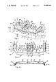
- FIG. 7 is a rear elevation thereof.
- FIG. 8 is a vertical section taken substantially along line 8--8 of FIG. 7: AND
- FIG. 9 is a vertical section taken substantially along line 9--9 of FIG. 7.
- a windshield visor 10 of the instant invention is shown externally positioned and mounted to a vehicle 12 which is here shown in phantom.
- the visor 10 extends over the windshield 14 of the vehicle.
- the windshield 14 provides the vehicle occupants and operator with protection while at the same time providing visibility for operation.
- the windshield 14 may also be known as a wind screen and typically is part of a wide variety of motor vehicles including pickup trucks, vans and the like.
- the visor 10 of the instant invention is mounted to the vehicle 12 and more particularly, to the exterior roof 16 of the vehicle to extend away therefrom.
- the visor 10 generally extends forwardly over the windshield 14 to act as a shield as can be seen in FIG. 1.
- the visor 10 extends outwardly a distance selected in proportion to the vehicle which is shown in FIG. 1.
- the visor 10 has a first shielding segment which extends inwardly from proximate a first outward end 20 and a second shielding segment 24 which extends inwardly from proximate a second outward end 26.
- the first shielding segment 18 and the second shielding segment 24 are in general planar alignment as can be seen in the figures. That is, the first and second segments 18 and 24 are each generally planar surfaces positioned over the left portion 14L and the right portion 14R of the windscreen 14 in the same general physical orientation with respect to the roof 16 and the windshield 14 to provide a uniform appearance and to be approximately the same height 15 from the bottom 17 of the windshield 14. As can be seen from the embodiment illustrated in FIG.
- the first segment 18 and the second segment 24 are substantially identical except that one is formed for the left side and the other for the right side. They may be regarded as symmetrically and proportionally positioned over their respective left portion 14L and right portion 14R of the windshield to in turn be what is here termed in general planar alignment.
- the first segment 18 extends from the outward end 20 inwardly a preselected distance 22 approximately the width of the left windshield segment 14L to an inward end 19 as shown in FIG. 2.
- the second shielding segment 24 extends from the second outward end 26 inwardly to an inward end 25 a preselected distance 28 as shown in FIG. 2.
- Support means 30 are positioned between and formed unitarily with the first and second shielding segments 18 and 24 to provide rigid support for the visor 10.
- the support means 30 here shown includes a first downwardly extending planar surface 32 and a second downwardly extending planar surface 34.
- the first and second downwardly extending planar surfaces 32 and 34 are each unitarily formed with the first and second shielding segments 18 and 24 respectively at their inward ends 19 and 25.
- the surfaces 32 and 34 are here shown to be generally mirror images of each other and extend downwardly to act as a rib. As best seen in FIG. 2, the surfaces 32 and 34 extend downwardly at a small angle from the vertical.
- the first and second downwardly extending generally planar surfaces 32 and 34 each have a lower edge 36 and 38 respectively.
- Interconnecting means 40 is unitarily formed with and extends between the lower edges 36 and 38 to rigidly interconnect the lower edges 36 and 38 and, in turn, the downwardly extending planar surfaces 32 and 34 and further, the first shielding segment 18 with the second shielding segment 24.
- the interconnecting means 40 is preferably planar surface means sized in width 42 to be in proportion generally as shown, which is less than half the width 22 and 28 of the shielding segments 18 and 24 which, a noted hereinbefore, are formed to be substantially symmetrical and as here illustrated to be substantially identical in width 22 and 28.
- the visor 10 also includes attaching means which are mechanically and unitarily formed with the first and second shielding segments 18 and 24 for mounting the visor 10 to the roof 16 of the vehicle 12.
- the attaching means here illustrated includes a first ear means, unitarily formed with the first shielding segment 18 at the outward end thereof 20.
- the first ear means 50 has portions 52 formed to conform to the roof 16 of the vehicle 12 with apertures 54 and 56 to accommodate appropriate fasteners.
- the attaching means also includes a second ear means 60 (FIG. 2) unitarily formed with the second shielding segment 24 at the outward end thereof 26.
- the second ear means 60 includes portions 62 formed to conform to the roof 16 of the vehicle 12, with appropriate apertures 64 and 66 to accommodate appropriate fasteners.
- the attaching means also includes a tongue means here shown to be centrally positioned approximately between the first shielding segment 18 and the second shielding segment 24 and integrally and unitarily formed with the interconnecting means 40.
- the tongue means 70 is integrally formed with the interconnecting means 40 as an extension thereof as can be seen in FIGS. 1 and 2.
- the tongue means is formed unitarily with the support means and interconnecting means and to conform with the roof 16 of the vehicle.
- the tongue means 70 may also include an angulated surface 72 formed to conform with the roof 16 of the vehicle.
- the tongue means preferably includes apertures 74, 76 and 78 to accommodate appropriate fastening devices to fasten the visor to the roof 16 of the vehicle 12.
- the first shielding segment 18 and the second shielding segment 24 each have a rearward edge 80 and 82 respectively.
- Generally planar surfaces 84 and 86 are each unitarily formed respectively with said first and second shielding segments 18 and 24 at the rearward edges 80 and 82 to extend between the first ear means 50 and the tongue means 70 and between the second ear means 60 and the tongue means 70 as shown.
- the generally planar surfaces 84 and 86 as shown are in general planar alignment with each other and have arcuate rear edges 88 and 90.
- first shielding segment 18 and the second shielding segment 24 each have respectively a front edge 92 and 94.
- a downwardly and inwardly extending lip 96 is unitarily formed therewith to extend along the width 22 and 28 of the first and second segments 18 and 24 respectively and along the front edge 98 of the interconnecting means 40 as well as around the first and second ends 20 and 26 respectively to extend rearwardly into the ear means 50 and 60 respectively as can be seen in perspective in FIG. 1.
- the first ear means 50 and the second ear means 60 each have portions 52 and 62 respectively which are formed to conform with the roof 16 of the vehicle 12. More particularly, the portions 52 and 62 include a rear portion 100 and 102, which are arcuately formed to conform to the shape of the roof 16 of the vehicle to which the visor 10 is attached.
- the ear portion also includes a downwardly extending portion 104 and 106 (FIG. 5 and 6) to provide for mounting of the visor 10 to the downwardly extending portions of the roof which may also be regarded as a door post or roof post 108.
Landscapes
- Engineering & Computer Science (AREA)
- Mechanical Engineering (AREA)
- Body Structure For Vehicles (AREA)
Abstract
Description
Claims (4)
Priority Applications (1)
| Application Number | Priority Date | Filing Date | Title |
|---|---|---|---|
| US07/677,593 US5108142A (en) | 1989-04-10 | 1991-03-27 | Windshield visor |
Applications Claiming Priority (2)
| Application Number | Priority Date | Filing Date | Title |
|---|---|---|---|
| US33656589A | 1989-04-10 | 1989-04-10 | |
| US07/677,593 US5108142A (en) | 1989-04-10 | 1991-03-27 | Windshield visor |
Related Parent Applications (1)
| Application Number | Title | Priority Date | Filing Date |
|---|---|---|---|
| US33656589A Continuation | 1989-04-10 | 1989-04-10 |
Publications (1)
| Publication Number | Publication Date |
|---|---|
| US5108142A true US5108142A (en) | 1992-04-28 |
Family
ID=26990270
Family Applications (1)
| Application Number | Title | Priority Date | Filing Date |
|---|---|---|---|
| US07/677,593 Expired - Lifetime US5108142A (en) | 1989-04-10 | 1991-03-27 | Windshield visor |
Country Status (1)
| Country | Link |
|---|---|
| US (1) | US5108142A (en) |
Cited By (9)
| Publication number | Priority date | Publication date | Assignee | Title |
|---|---|---|---|---|
| US5452933A (en) * | 1994-08-02 | 1995-09-26 | Dfm Corporation | Visor accessory with sun shield insert |
| WO1997015466A1 (en) * | 1995-10-23 | 1997-05-01 | Lund Industries, Inc. | Windshield visor for motor vehicles |
| USD382238S (en) * | 1995-09-20 | 1997-08-12 | Fink Kenneth M | Rooftop spoiler |
| US5664871A (en) * | 1996-10-30 | 1997-09-09 | Dfm Corporation | Visor with recessed mounting caps on trailing edge |
| USD413846S (en) * | 1998-07-10 | 1999-09-14 | Lund Industries, Incorporated | Windshield visor for motor vehicles |
| US6045075A (en) * | 1997-10-09 | 2000-04-04 | Shimano, Inc. | Low profile double bearing reel having thumb rest |
| US20060091691A1 (en) * | 2004-10-28 | 2006-05-04 | Steve Drabant | Vehicle windshield visor |
| WO2010034421A2 (en) * | 2008-09-23 | 2010-04-01 | Schalker Eisenhütte Maschinenfabrik Gmbh | Locomotive |
| US20110018304A1 (en) * | 2009-07-24 | 2011-01-27 | International Truck Intellectual Property Company Llc | System for increasing a field of view of a user of a vehicle |
Citations (15)
| Publication number | Priority date | Publication date | Assignee | Title |
|---|---|---|---|---|
| US2475901A (en) * | 1948-02-09 | 1949-07-12 | William T Kipp | Sun visor |
| US2534763A (en) * | 1948-05-17 | 1950-12-19 | Clarence B Flavin | Exterior-type sun visor |
| US2566934A (en) * | 1949-07-06 | 1951-09-04 | Richard E Dieterich | Combined vehicle windshield shade and traffic signal finder |
| US2567501A (en) * | 1948-05-27 | 1951-09-11 | George J Zeis | Visor for automobiles |
| US2599809A (en) * | 1949-02-25 | 1952-06-10 | William F Branch | Sun visor for motor vehicles |
| US2777732A (en) * | 1954-12-01 | 1957-01-15 | Thomas S Walsh | Clear vision rain visors |
| GB829154A (en) * | 1957-08-08 | 1960-02-24 | Denis James Battersby | Exterior windscreen visor for vehicles |
| US3214216A (en) * | 1962-12-31 | 1965-10-26 | Jr George E Brown | Disposable windshield canopy |
| US4018472A (en) * | 1976-02-04 | 1977-04-19 | General Motors Corporation | Tractor-trailer aerodynamic drag reducer |
| US4149749A (en) * | 1977-02-11 | 1979-04-17 | Exacon International-Establishment | Roof lining element for vehicle cabins |
| US4320919A (en) * | 1978-12-21 | 1982-03-23 | Affiliated Hatch And Sunroof, Inc. | Aerodynamic visor |
| US4412698A (en) * | 1981-08-18 | 1983-11-01 | Kingsley Michael C | Method and apparatus for attaching sun visor to an automobile |
| US4726519A (en) * | 1986-01-27 | 1988-02-23 | S. C. Johnson & Son, Inc. | Instant/continuous air-treatment device |
| US4758040A (en) * | 1986-04-07 | 1988-07-19 | Michael C. Kingsley | Exterior visor for automotive vehicles |
| US4842320A (en) * | 1986-10-03 | 1989-06-27 | Saturn Corporation | Vehicle exterior sun visor |
-
1991
- 1991-03-27 US US07/677,593 patent/US5108142A/en not_active Expired - Lifetime
Patent Citations (15)
| Publication number | Priority date | Publication date | Assignee | Title |
|---|---|---|---|---|
| US2475901A (en) * | 1948-02-09 | 1949-07-12 | William T Kipp | Sun visor |
| US2534763A (en) * | 1948-05-17 | 1950-12-19 | Clarence B Flavin | Exterior-type sun visor |
| US2567501A (en) * | 1948-05-27 | 1951-09-11 | George J Zeis | Visor for automobiles |
| US2599809A (en) * | 1949-02-25 | 1952-06-10 | William F Branch | Sun visor for motor vehicles |
| US2566934A (en) * | 1949-07-06 | 1951-09-04 | Richard E Dieterich | Combined vehicle windshield shade and traffic signal finder |
| US2777732A (en) * | 1954-12-01 | 1957-01-15 | Thomas S Walsh | Clear vision rain visors |
| GB829154A (en) * | 1957-08-08 | 1960-02-24 | Denis James Battersby | Exterior windscreen visor for vehicles |
| US3214216A (en) * | 1962-12-31 | 1965-10-26 | Jr George E Brown | Disposable windshield canopy |
| US4018472A (en) * | 1976-02-04 | 1977-04-19 | General Motors Corporation | Tractor-trailer aerodynamic drag reducer |
| US4149749A (en) * | 1977-02-11 | 1979-04-17 | Exacon International-Establishment | Roof lining element for vehicle cabins |
| US4320919A (en) * | 1978-12-21 | 1982-03-23 | Affiliated Hatch And Sunroof, Inc. | Aerodynamic visor |
| US4412698A (en) * | 1981-08-18 | 1983-11-01 | Kingsley Michael C | Method and apparatus for attaching sun visor to an automobile |
| US4726519A (en) * | 1986-01-27 | 1988-02-23 | S. C. Johnson & Son, Inc. | Instant/continuous air-treatment device |
| US4758040A (en) * | 1986-04-07 | 1988-07-19 | Michael C. Kingsley | Exterior visor for automotive vehicles |
| US4842320A (en) * | 1986-10-03 | 1989-06-27 | Saturn Corporation | Vehicle exterior sun visor |
Non-Patent Citations (1)
| Title |
|---|
| Sun Visor Product Catalog, undated. * |
Cited By (13)
| Publication number | Priority date | Publication date | Assignee | Title |
|---|---|---|---|---|
| US5522634A (en) * | 1994-08-02 | 1996-06-04 | Dfm Corporation | Visor accessory with sun shield insert and running lights |
| US5452933A (en) * | 1994-08-02 | 1995-09-26 | Dfm Corporation | Visor accessory with sun shield insert |
| USD382238S (en) * | 1995-09-20 | 1997-08-12 | Fink Kenneth M | Rooftop spoiler |
| US6367860B1 (en) | 1995-10-23 | 2002-04-09 | Lund Industries, Incorporated | Windshield visor for motor vehicles |
| WO1997015466A1 (en) * | 1995-10-23 | 1997-05-01 | Lund Industries, Inc. | Windshield visor for motor vehicles |
| US5851044A (en) * | 1995-10-23 | 1998-12-22 | Lund; David | Windshield visor for motor vehicles |
| US5664871A (en) * | 1996-10-30 | 1997-09-09 | Dfm Corporation | Visor with recessed mounting caps on trailing edge |
| US6045075A (en) * | 1997-10-09 | 2000-04-04 | Shimano, Inc. | Low profile double bearing reel having thumb rest |
| USD413846S (en) * | 1998-07-10 | 1999-09-14 | Lund Industries, Incorporated | Windshield visor for motor vehicles |
| US20060091691A1 (en) * | 2004-10-28 | 2006-05-04 | Steve Drabant | Vehicle windshield visor |
| WO2010034421A2 (en) * | 2008-09-23 | 2010-04-01 | Schalker Eisenhütte Maschinenfabrik Gmbh | Locomotive |
| WO2010034421A3 (en) * | 2008-09-23 | 2010-07-01 | Schalker Eisenhütte Maschinenfabrik Gmbh | Locomotive |
| US20110018304A1 (en) * | 2009-07-24 | 2011-01-27 | International Truck Intellectual Property Company Llc | System for increasing a field of view of a user of a vehicle |
Similar Documents
| Publication | Publication Date | Title |
|---|---|---|
| USD413856S (en) | Overhead console with flip-down television screen for a motor vehicle | |
| US4627657A (en) | Truck deflector shield | |
| US4824231A (en) | Broad angle rear view mirror assembly | |
| US4726619A (en) | Split universal sun visor for a vehicle windshield | |
| USD314163S (en) | Vehicle roof | |
| US4966404A (en) | Windshield visor for trucks having cab roof lights | |
| US5108142A (en) | Windshield visor | |
| US4892401A (en) | Auxiliary side view mirror module | |
| US4863254A (en) | Side view mirror attachment | |
| GB2210835A (en) | Vehicle forward view mirror | |
| US3972601A (en) | Peripheral vision non-distorting rear view mirror | |
| USD489657S1 (en) | Vehicle side view mirror | |
| US6070896A (en) | Seat fixing structure of motorcycle | |
| EP0919452A3 (en) | Bumper-mounting structure for frame-mounted-body vehicle | |
| CA2038016A1 (en) | Windshield Deflector Shield with Lens and/or Rearview Mirrors | |
| US6705661B2 (en) | Unitary visor attachment | |
| US5845983A (en) | Vehicle light mounting system | |
| USD422544S (en) | Spoiler | |
| US5651577A (en) | Visor extension | |
| US4093263A (en) | Safety bicycle seat reflector | |
| US5924756A (en) | Airfoil for sport vehicles | |
| US5062675A (en) | ATV guard apparatus | |
| CA2008527C (en) | Rearview mirror | |
| WO2006078263A1 (en) | Rearview mirror assembly | |
| CA1161081A (en) | Sun visor system for trucks |
Legal Events
| Date | Code | Title | Description |
|---|---|---|---|
| STCF | Information on status: patent grant |
Free format text: PATENTED CASE |
|
| FEPP | Fee payment procedure |
Free format text: PAYOR NUMBER ASSIGNED (ORIGINAL EVENT CODE: ASPN); ENTITY STATUS OF PATENT OWNER: LARGE ENTITY |
|
| REMI | Maintenance fee reminder mailed | ||
| FPAY | Fee payment |
Year of fee payment: 4 |
|
| SULP | Surcharge for late payment | ||
| AS | Assignment |
Owner name: HELLER FINANCIAL, INC. AS AGENT, ILLINOIS Free format text: SECURITY INTEREST;ASSIGNOR:LUND INDUSTRIES, INCORPORATED;REEL/FRAME:009168/0026 Effective date: 19980227 |
|
| FPAY | Fee payment |
Year of fee payment: 8 |
|
| SULP | Surcharge for late payment | ||
| FEPP | Fee payment procedure |
Free format text: PAT HOLDER NO LONGER CLAIMS SMALL ENTITY STATUS, ENTITY STATUS SET TO UNDISCOUNTED (ORIGINAL EVENT CODE: STOL); ENTITY STATUS OF PATENT OWNER: LARGE ENTITY |
|
| AS | Assignment |
Owner name: LUND INTERNATIONAL, INC., MINNESOTA Free format text: MERGER;ASSIGNOR:LUND INDUSTRIES, INCORPORATED;REEL/FRAME:013835/0221 Effective date: 20030227 |
|
| AS | Assignment |
Owner name: LUND INDUSTRIES, INCORPORATED, GEORGIA Free format text: RELEASE AND REASSIGNMENT;ASSIGNOR:HELLER FINANCIAL, INC., AS AGENT;REEL/FRAME:013868/0016 Effective date: 20030228 |
|
| AS | Assignment |
Owner name: GENERAL ELECTRIC CAPITAL CORPORATION, NEW YORK Free format text: SECURITY AGREEMENT;ASSIGNOR:LUND INTERNATIONAL, INC.;REEL/FRAME:013845/0588 Effective date: 20030228 |
|
| FEPP | Fee payment procedure |
Free format text: ENTITY STATUS SET TO UNDISCOUNTED (ORIGINAL EVENT CODE: BIG.); ENTITY STATUS OF PATENT OWNER: LARGE ENTITY |
|
| FPAY | Fee payment |
Year of fee payment: 12 |
|
| AS | Assignment |
Owner name: LUND, INC., GEORGIA Free format text: ASSIGNMENT OF ASSIGNORS INTEREST;ASSIGNORS:LUND INTERNATIONAL HOLDINGS, INC.;LUND INTERNATIONAL, INC.;REEL/FRAME:020317/0743 Effective date: 20071129 |
|
| AS | Assignment |
Owner name: GENERAL ELECTRIC CAPITAL CORPORATION, AS ADMINISTR Free format text: SECURITY AGREEMENT;ASSIGNOR:LUND, INC.;REEL/FRAME:020403/0930 Effective date: 20071130 |
|
| AS | Assignment |
Owner name: BELMOR, INC., GEORGIA Free format text: RELEASE BY SECURED PARTY;ASSIGNOR:GENERAL ELECTRIC CAPITAL CORPORATION;REEL/FRAME:026205/0422 Effective date: 20110427 Owner name: LUND, INC., GEORGIA Free format text: RELEASE BY SECURED PARTY;ASSIGNOR:GENERAL ELECTRIC CAPITAL CORPORATION;REEL/FRAME:026205/0422 Effective date: 20110427 Owner name: LUND INTERNATINAL, INC., GEORGIA Free format text: RELEASE BY SECURED PARTY;ASSIGNOR:GENERAL ELECTRIC CAPITAL CORPORATION;REEL/FRAME:026205/0422 Effective date: 20110427 |