US5131084A - Method and apparatus for synchronization management of timers in distributed data processing system - Google Patents
Method and apparatus for synchronization management of timers in distributed data processing system Download PDFInfo
- Publication number
- US5131084A US5131084A US07/497,815 US49781590A US5131084A US 5131084 A US5131084 A US 5131084A US 49781590 A US49781590 A US 49781590A US 5131084 A US5131084 A US 5131084A
- Authority
- US
- United States
- Prior art keywords
- processor
- timer
- time data
- identification code
- processors
- Prior art date
- Legal status (The legal status is an assumption and is not a legal conclusion. Google has not performed a legal analysis and makes no representation as to the accuracy of the status listed.)
- Expired - Fee Related
Links
Images


Classifications
-
- G—PHYSICS
- G06—COMPUTING; CALCULATING OR COUNTING
- G06F—ELECTRIC DIGITAL DATA PROCESSING
- G06F9/00—Arrangements for program control, e.g. control units
- G06F9/06—Arrangements for program control, e.g. control units using stored programs, i.e. using an internal store of processing equipment to receive or retain programs
- G06F9/46—Multiprogramming arrangements
- G06F9/48—Program initiating; Program switching, e.g. by interrupt
- G06F9/4806—Task transfer initiation or dispatching
- G06F9/4812—Task transfer initiation or dispatching by interrupt, e.g. masked
- G06F9/4825—Interrupt from clock, e.g. time of day
-
- G—PHYSICS
- G06—COMPUTING; CALCULATING OR COUNTING
- G06F—ELECTRIC DIGITAL DATA PROCESSING
- G06F9/00—Arrangements for program control, e.g. control units
- G06F9/06—Arrangements for program control, e.g. control units using stored programs, i.e. using an internal store of processing equipment to receive or retain programs
- G06F9/46—Multiprogramming arrangements
- G06F9/52—Program synchronisation; Mutual exclusion, e.g. by means of semaphores
Definitions
- This invention relates to a distributed data processing system of the type wherein a plurality of processors are connected to one another through a transmission line, and more particularly to a method and apparatus for synchronization management of timers of a plurality of processors for the same or each group.
- a conventional timer synchronization management method is described, for example, in Japanese Patent Laid-Open No. 135,565/1984.
- a plurality of processors are connected to one another through a transmission line, a particular processor is defined as a "master" with the others being “slaves” for timer synchronization and the timer of each processor is synchronized by a synchronization instruction of the master processor.
- the first characterized feature of the present invention lies in that a master-slave relationship for timer synchronization is not employed but each processor selects an arbitrary processor at its own judgement and sets the time of the selected processor to the timer of its own system.
- the second characterizing feature of the present invention lies in that each processor selects an arbitrary processor in the same group at its own judgement and sets the time of the selected processor to the timer of its own system.
- each processor broadcasts the time of its own system on a transmission line, and each processor receives it from the transmission line. If the broadcasting processor has the time of the processor as the object of synchronization, the receiving processor sets the time to the timer of its own system, and the timers between the processors can thus be synchronized.
- each receiving processor sets the time to the timer of its own system in order to synchronize the timers among the processors of the same group.
- FIG. 1 is a block diagram showing a timer synchronization system in accordance with one embodiment of the present invention
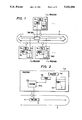
- FIG. 2 is a block diagram showing a time data transmission system
- FIG. 3 is a block diagram showing a time data reception system
- FIG. 4 shows a message format of the time data
- FIG. 5 shows a timer synchronization table
- FIG. 6 is a flowchart showing transmission processing of the time data
- FIG. 7 is a flowchart showing reception processing of the time data.
- FIG. 8 is a block diagram showing another embodiment of the present invention.
- a plurality of processors 1 (a, b, c, . . . . ) are connected to one another through a transmission line 2.
- Each processor has a timer 3 (a, b, c, . . . ).
- the value of the timer 3a is broadcasted on the transmission line as time data 6.
- the timer data 6 is received by each processor 1-b, 1-c and stored in a timer synchronization table 4b, 4c.
- Each processor 1-b, 1-c reads out the time of a processor as the object of synchronization from the timer synchronization table 4b, 4c and sets it to the timer 3b, 3c of its own system.
- FIG. 2 shows a transmission system of the time data in the processor 1-a.
- a transmission program 30a reads out the time from the timer 3a of the processor 1-a and broadcasts it as time data 6 on the transmission line 2. At this time, the timer synchronization table 4a and a synchronization designation value 5a are not used.
- FIG. 3 shows a reception system of the time data in the processor 1-b .
- the time data 6 broadcasted on the transmission line 2 is received by the reception program 40b inside the processor 1-b.
- the time data 6 thus received is stored in the timer synchronization table 4b.
- the timer of the processor designated by the synchronization designation value 5b is read out from the timer synchronization table 4b and set to the timer 3b of the processor 1-b. In this manner, the timers among the processors can be synchronized.
- FIG. 4 shows a message format of the time data.
- the message broadcasted to the transmission line consists of a message control field 71, a transmititng group number 72, a transmitting node number and the time data 74.
- the transmitting group number 72 may be omitted when management of each group unit is not effected.
- the message control unit 71 contains identification information representing whether or not the message is the time data, or information representing the length of the message.
- the time data 74 includes, for example, the data of year, month, day, time, minute and second.
- FIG. 5 shows the timer synchronization table 4.
- One element of the timer synchronization table consists of a group number 41, a node number 42 and time data 43.
- the number of this table is preferably the same as the number of processors to be connected to the transmission line.
- the group number may be omitted when management of group unit is not effected.
- FIG. 6 shows transmission processing of the time data. Transmission processing is fundamentally evoked at predetermined periods. Whether or not transmission of the time data is necessary is judged at step 81. If it is judged necessary, the time data of its own system is broadcasted to the transmission line at step 82.
- FIG. 7 shows reception processing of the time data.
- the time data is received from the transmission line at step 91.
- the time data thus received is stored in the timer synchronization table of its own system at step 92.
- Next, whether or not the transmitting group number of the time data received is in conformity with the group number dealt with as the object of synchronization in its own system is judged at step 93. If they are in conformity, processing of step 94 is executed. Namely, at this step 94, whether or not the transmitting node (processor) number of the time data received is in agreement with the node number as the object of synchronization in its own system is judged. If they are in conformity, the time is set to the timer of its own system at step 95.
- FIG. 8 shows another embodiment of the present invention.
- the diagram shows the embodiment wherein the processors 1-a to 1-c are managed as a group I while the processors 1-x to 1-z are managed as another group II.
- a plurality of processors 1-a to 1-z are connected to one another through the transmission line 2.
- the timers 3a, 3x of the processors 1-a, 1-x are broadcasted as the time data 6-I, 6-II to the transmission line 2, respectively.
- the time data 6-I, 6-II thus broadcasted are received by the processors 1-b, 1-c, 1-y, 1-z and synchronized with the timer of the processor as the object of synchronization within the same group I, II.
- one group I can be used for on-line application while the other group II can be used for testing purpose, so that testing efficiency can be improved.
- the present invention can improve extensibility, maintenance and reliability of the distributed data processing system.
- the present invention can manage the processors for each group and can synchronize the timers among the processors of the same group. Therefore, the present invention can improve testing efficiency in the distributed data processing system in addition to the improvement in extensibility, maintenance and reliability of the system.
Abstract
Description
Claims (10)
Applications Claiming Priority (2)
| Application Number | Priority Date | Filing Date | Title |
|---|---|---|---|
| JP61-157838 | 1986-07-07 | ||
| JP61157838A JPS6315354A (en) | 1986-07-07 | 1986-07-07 | Timer conformity control system in distributed system |
Related Parent Applications (1)
| Application Number | Title | Priority Date | Filing Date |
|---|---|---|---|
| US07070431 Continuation | 1987-07-07 |
Publications (1)
| Publication Number | Publication Date |
|---|---|
| US5131084A true US5131084A (en) | 1992-07-14 |
Family
ID=15658447
Family Applications (1)
| Application Number | Title | Priority Date | Filing Date |
|---|---|---|---|
| US07/497,815 Expired - Fee Related US5131084A (en) | 1986-07-07 | 1990-03-22 | Method and apparatus for synchronization management of timers in distributed data processing system |
Country Status (2)
| Country | Link |
|---|---|
| US (1) | US5131084A (en) |
| JP (1) | JPS6315354A (en) |
Cited By (10)
| Publication number | Priority date | Publication date | Assignee | Title |
|---|---|---|---|---|
| US5307495A (en) * | 1987-10-23 | 1994-04-26 | Hitachi, Ltd. | Multiprocessor system statically dividing processors into groups allowing processor of selected group to send task requests only to processors of selected group |
| US5548750A (en) * | 1992-12-08 | 1996-08-20 | Telefonaktiebolaget Lm Ericsson | System for taking backup in a data base |
| US5659683A (en) * | 1993-12-27 | 1997-08-19 | Hitachi, Ltd. | Distributed computer system and method using a common transmission line in a plurality of processors interconneted for executing a program module utilizing attributes |
| US5805870A (en) * | 1996-06-28 | 1998-09-08 | International Business Machines Corporation | System and method for correcting clock drift in multiprocessor systems |
| US5892981A (en) * | 1996-10-10 | 1999-04-06 | Hewlett-Packard Company | Memory system and device |
| US5918040A (en) * | 1992-10-01 | 1999-06-29 | Cabletron Systems, Inc. | Method for maintaining time synchronization between two processors in a network interface |
| US6144961A (en) * | 1995-08-31 | 2000-11-07 | Compuware Corporation | Method and system for non-intrusive measurement of transaction response times on a network |
| US20060262814A1 (en) * | 2003-05-20 | 2006-11-23 | Ungermann Joern | Time-triggered communication system and method for the synchronization of a dual-channel network |
| US20090307610A1 (en) * | 2008-06-10 | 2009-12-10 | Melonie Elizabeth Ryan | Method for a plurality of users to be simultaneously matched to interact one on one in a live controlled environment |
| US9733664B1 (en) * | 2013-03-14 | 2017-08-15 | Gamesys Ltd. | Method for expiring fault-tolerant timers using distributed locks |
Citations (6)
| Publication number | Priority date | Publication date | Assignee | Title |
|---|---|---|---|---|
| US4154983A (en) * | 1978-03-13 | 1979-05-15 | Bell Telephone Laboratories, Incorporated | Loop carrier system for telecommunication and data services |
| US4337463A (en) * | 1980-08-22 | 1982-06-29 | Control Data Corporation | Time synchronization master station and remote station system |
| US4531185A (en) * | 1983-08-31 | 1985-07-23 | International Business Machines Corporation | Centralized synchronization of clocks |
| US4709347A (en) * | 1984-12-17 | 1987-11-24 | Honeywell Inc. | Method and apparatus for synchronizing the timing subsystems of the physical modules of a local area network |
| US4736393A (en) * | 1986-04-16 | 1988-04-05 | American Telephone And Telegraph Co., At&T Information Systems, Inc. | Distributed timing control for a distributed digital communication system |
| US4746920A (en) * | 1986-03-28 | 1988-05-24 | Tandem Computers Incorporated | Method and apparatus for clock management |
-
1986
- 1986-07-07 JP JP61157838A patent/JPS6315354A/en active Granted
-
1990
- 1990-03-22 US US07/497,815 patent/US5131084A/en not_active Expired - Fee Related
Patent Citations (6)
| Publication number | Priority date | Publication date | Assignee | Title |
|---|---|---|---|---|
| US4154983A (en) * | 1978-03-13 | 1979-05-15 | Bell Telephone Laboratories, Incorporated | Loop carrier system for telecommunication and data services |
| US4337463A (en) * | 1980-08-22 | 1982-06-29 | Control Data Corporation | Time synchronization master station and remote station system |
| US4531185A (en) * | 1983-08-31 | 1985-07-23 | International Business Machines Corporation | Centralized synchronization of clocks |
| US4709347A (en) * | 1984-12-17 | 1987-11-24 | Honeywell Inc. | Method and apparatus for synchronizing the timing subsystems of the physical modules of a local area network |
| US4746920A (en) * | 1986-03-28 | 1988-05-24 | Tandem Computers Incorporated | Method and apparatus for clock management |
| US4736393A (en) * | 1986-04-16 | 1988-04-05 | American Telephone And Telegraph Co., At&T Information Systems, Inc. | Distributed timing control for a distributed digital communication system |
Cited By (11)
| Publication number | Priority date | Publication date | Assignee | Title |
|---|---|---|---|---|
| US5307495A (en) * | 1987-10-23 | 1994-04-26 | Hitachi, Ltd. | Multiprocessor system statically dividing processors into groups allowing processor of selected group to send task requests only to processors of selected group |
| US5918040A (en) * | 1992-10-01 | 1999-06-29 | Cabletron Systems, Inc. | Method for maintaining time synchronization between two processors in a network interface |
| US5548750A (en) * | 1992-12-08 | 1996-08-20 | Telefonaktiebolaget Lm Ericsson | System for taking backup in a data base |
| US5659683A (en) * | 1993-12-27 | 1997-08-19 | Hitachi, Ltd. | Distributed computer system and method using a common transmission line in a plurality of processors interconneted for executing a program module utilizing attributes |
| US6144961A (en) * | 1995-08-31 | 2000-11-07 | Compuware Corporation | Method and system for non-intrusive measurement of transaction response times on a network |
| US5805870A (en) * | 1996-06-28 | 1998-09-08 | International Business Machines Corporation | System and method for correcting clock drift in multiprocessor systems |
| US5892981A (en) * | 1996-10-10 | 1999-04-06 | Hewlett-Packard Company | Memory system and device |
| US20060262814A1 (en) * | 2003-05-20 | 2006-11-23 | Ungermann Joern | Time-triggered communication system and method for the synchronization of a dual-channel network |
| US7848361B2 (en) * | 2003-05-20 | 2010-12-07 | Nxp B.V. | Time-triggered communication system and method for the synchronization of a dual-channel network |
| US20090307610A1 (en) * | 2008-06-10 | 2009-12-10 | Melonie Elizabeth Ryan | Method for a plurality of users to be simultaneously matched to interact one on one in a live controlled environment |
| US9733664B1 (en) * | 2013-03-14 | 2017-08-15 | Gamesys Ltd. | Method for expiring fault-tolerant timers using distributed locks |
Also Published As
| Publication number | Publication date |
|---|---|
| JPH0410103B2 (en) | 1992-02-24 |
| JPS6315354A (en) | 1988-01-22 |
Similar Documents
| Publication | Publication Date | Title |
|---|---|---|
| US4347606A (en) | Method of frame synchronization of a digital TDM communication system and arrangement for performing the method | |
| CN110798499B (en) | Distributed service coordination system and method | |
| US4837850A (en) | Hierarchic synchronization method and circuit arrangement for exchanges of a mesh telecommunication network | |
| US5131084A (en) | Method and apparatus for synchronization management of timers in distributed data processing system | |
| DE4292401C1 (en) | Device and method for forwarding digitised analog messages and digital data messages from a user interface to a processing section of a radiotelephone | |
| DE69432842T2 (en) | Communication network with time-coordinated station activity | |
| US4870571A (en) | Intercomputer communications based on message broadcasting with receiver selection | |
| DE3642019C2 (en) | ||
| DE69433858T2 (en) | Method and apparatus for exchanging different types of data during different time intervals | |
| US5274637A (en) | Token-ring-type local area network | |
| AU6278896A (en) | Intelligent memory management system and method | |
| US7124151B1 (en) | Database synchronization apparatus in element management system and method therefor | |
| DE69433232T2 (en) | Digital news network with the selection process of a moderator station | |
| US5497374A (en) | Data transmission method and system thereof | |
| US6357014B1 (en) | Device for monitoring the periodicity of the messages sent over a multiplexed transmission network with a can-type structure | |
| US4831512A (en) | System and method of message communication capable of checking consistency among data | |
| US5144295A (en) | Interruption processing system in time division multiplex transmission system | |
| DE3729732A1 (en) | Data transmission method and device | |
| CA1241776A (en) | Device for performing wrap tests on a multiplex link in a data communication system | |
| JP2000269988A (en) | Multiple address data transmission system | |
| DE2843179C2 (en) | Code converter device for processing coded switching information transmitted during cyclically successive time frames | |
| DE60211222T2 (en) | METHOD AND DEVICE FOR DATA COMMUNICATION IN A NETWORK-CONTROLLED SYSTEM | |
| JP2702218B2 (en) | Wireless communication system | |
| US5519385A (en) | Circuit for switching signal processing circuits | |
| JPS589620B2 (en) | Peer communication system |
Legal Events
| Date | Code | Title | Description |
|---|---|---|---|
| AS | Assignment |
Owner name: HITACHI, LTD., A CORP. OF JAPAN, JAPAN Free format text: ASSIGNMENT OF ASSIGNORS INTEREST.;ASSIGNORS:KASASHIMA, HIROKAZU;KAWAKAMI, SETSUO;HORI, SHINJI;AND OTHERS;REEL/FRAME:006017/0967 Effective date: 19870618 |
|
| FEPP | Fee payment procedure |
Free format text: PAYOR NUMBER ASSIGNED (ORIGINAL EVENT CODE: ASPN); ENTITY STATUS OF PATENT OWNER: LARGE ENTITY |
|
| FPAY | Fee payment |
Year of fee payment: 4 |
|
| FPAY | Fee payment |
Year of fee payment: 8 |
|
| REMI | Maintenance fee reminder mailed | ||
| LAPS | Lapse for failure to pay maintenance fees | ||
| FP | Lapsed due to failure to pay maintenance fee |
Effective date: 20040714 |
|
| STCH | Information on status: patent discontinuation |
Free format text: PATENT EXPIRED DUE TO NONPAYMENT OF MAINTENANCE FEES UNDER 37 CFR 1.362 |