US5151908A - Laser with longitudinal mode selection - Google Patents
Laser with longitudinal mode selection Download PDFInfo
- Publication number
- US5151908A US5151908A US07/770,762 US77076291A US5151908A US 5151908 A US5151908 A US 5151908A US 77076291 A US77076291 A US 77076291A US 5151908 A US5151908 A US 5151908A
- Authority
- US
- United States
- Prior art keywords
- laser
- fabry
- cavity
- accordance
- grating
- Prior art date
- Legal status (The legal status is an assumption and is not a legal conclusion. Google has not performed a legal analysis and makes no representation as to the accuracy of the status listed.)
- Expired - Lifetime
Links
Images


Classifications
-
- H—ELECTRICITY
- H01—ELECTRIC ELEMENTS
- H01S—DEVICES USING THE PROCESS OF LIGHT AMPLIFICATION BY STIMULATED EMISSION OF RADIATION [LASER] TO AMPLIFY OR GENERATE LIGHT; DEVICES USING STIMULATED EMISSION OF ELECTROMAGNETIC RADIATION IN WAVE RANGES OTHER THAN OPTICAL
- H01S3/00—Lasers, i.e. devices using stimulated emission of electromagnetic radiation in the infrared, visible or ultraviolet wave range
- H01S3/05—Construction or shape of optical resonators; Accommodation of active medium therein; Shape of active medium
- H01S3/08—Construction or shape of optical resonators or components thereof
- H01S3/08018—Mode suppression
- H01S3/08022—Longitudinal modes
- H01S3/08031—Single-mode emission
- H01S3/08036—Single-mode emission using intracavity dispersive, polarising or birefringent elements
-
- H—ELECTRICITY
- H01—ELECTRIC ELEMENTS
- H01S—DEVICES USING THE PROCESS OF LIGHT AMPLIFICATION BY STIMULATED EMISSION OF RADIATION [LASER] TO AMPLIFY OR GENERATE LIGHT; DEVICES USING STIMULATED EMISSION OF ELECTROMAGNETIC RADIATION IN WAVE RANGES OTHER THAN OPTICAL
- H01S3/00—Lasers, i.e. devices using stimulated emission of electromagnetic radiation in the infrared, visible or ultraviolet wave range
- H01S3/05—Construction or shape of optical resonators; Accommodation of active medium therein; Shape of active medium
- H01S3/06—Construction or shape of active medium
- H01S3/063—Waveguide lasers, i.e. whereby the dimensions of the waveguide are of the order of the light wavelength
- H01S3/067—Fibre lasers
-
- H—ELECTRICITY
- H01—ELECTRIC ELEMENTS
- H01S—DEVICES USING THE PROCESS OF LIGHT AMPLIFICATION BY STIMULATED EMISSION OF RADIATION [LASER] TO AMPLIFY OR GENERATE LIGHT; DEVICES USING STIMULATED EMISSION OF ELECTROMAGNETIC RADIATION IN WAVE RANGES OTHER THAN OPTICAL
- H01S3/00—Lasers, i.e. devices using stimulated emission of electromagnetic radiation in the infrared, visible or ultraviolet wave range
- H01S3/05—Construction or shape of optical resonators; Accommodation of active medium therein; Shape of active medium
- H01S3/08—Construction or shape of optical resonators or components thereof
- H01S3/081—Construction or shape of optical resonators or components thereof comprising three or more reflectors
- H01S3/083—Ring lasers
-
- H—ELECTRICITY
- H01—ELECTRIC ELEMENTS
- H01S—DEVICES USING THE PROCESS OF LIGHT AMPLIFICATION BY STIMULATED EMISSION OF RADIATION [LASER] TO AMPLIFY OR GENERATE LIGHT; DEVICES USING STIMULATED EMISSION OF ELECTROMAGNETIC RADIATION IN WAVE RANGES OTHER THAN OPTICAL
- H01S3/00—Lasers, i.e. devices using stimulated emission of electromagnetic radiation in the infrared, visible or ultraviolet wave range
- H01S3/05—Construction or shape of optical resonators; Accommodation of active medium therein; Shape of active medium
- H01S3/06—Construction or shape of active medium
- H01S3/063—Waveguide lasers, i.e. whereby the dimensions of the waveguide are of the order of the light wavelength
- H01S3/067—Fibre lasers
- H01S3/0675—Resonators including a grating structure, e.g. distributed Bragg reflectors [DBR] or distributed feedback [DFB] fibre lasers
-
- H—ELECTRICITY
- H01—ELECTRIC ELEMENTS
- H01S—DEVICES USING THE PROCESS OF LIGHT AMPLIFICATION BY STIMULATED EMISSION OF RADIATION [LASER] TO AMPLIFY OR GENERATE LIGHT; DEVICES USING STIMULATED EMISSION OF ELECTROMAGNETIC RADIATION IN WAVE RANGES OTHER THAN OPTICAL
- H01S3/00—Lasers, i.e. devices using stimulated emission of electromagnetic radiation in the infrared, visible or ultraviolet wave range
- H01S3/05—Construction or shape of optical resonators; Accommodation of active medium therein; Shape of active medium
- H01S3/06—Construction or shape of active medium
- H01S3/063—Waveguide lasers, i.e. whereby the dimensions of the waveguide are of the order of the light wavelength
- H01S3/067—Fibre lasers
- H01S3/06791—Fibre ring lasers
-
- H—ELECTRICITY
- H01—ELECTRIC ELEMENTS
- H01S—DEVICES USING THE PROCESS OF LIGHT AMPLIFICATION BY STIMULATED EMISSION OF RADIATION [LASER] TO AMPLIFY OR GENERATE LIGHT; DEVICES USING STIMULATED EMISSION OF ELECTROMAGNETIC RADIATION IN WAVE RANGES OTHER THAN OPTICAL
- H01S3/00—Lasers, i.e. devices using stimulated emission of electromagnetic radiation in the infrared, visible or ultraviolet wave range
- H01S3/14—Lasers, i.e. devices using stimulated emission of electromagnetic radiation in the infrared, visible or ultraviolet wave range characterised by the material used as the active medium
- H01S3/16—Solid materials
- H01S3/1601—Solid materials characterised by an active (lasing) ion
- H01S3/1603—Solid materials characterised by an active (lasing) ion rare earth
- H01S3/1608—Solid materials characterised by an active (lasing) ion rare earth erbium
Definitions
- the present invention relates to lasers, and more particularly, to a rare earth element doped laser with longitudinal mode selection.
- the doped laser is implemented in an optical transmission medium such as an optical fiber or silica waveguide.
- the rare earth material can comprise, for example, Erbium or Neodymium.
- optical fiber technology is expanding at a rapid pace. Telecommunication, sensors, medical and video transmission can all take advantage of optical technology, particularly where virtually unlimited bandwidth and low attenuation are beneficial.
- Cable television systems are one example where optical fiber technology is providing efficient and economical alternatives to prior coaxial cable distribution schemes.
- beating will occur (e.g., between optical longitudinal modes that fall in the radio frequency domain) resulting in unacceptable levels of noise in the RF band of interest.
- Those modes of laser operation that are close enough together to be on the order of RF frequencies (i.e., 5.75 MHz to 550 MHz or higher for the cable television spectrum) must be suppressed in order to use such lasers for CATV applications. After suppression, the only remaining modes will not produce beat frequencies in the RF domain.
- Multiple longitudinal operation may also exhibit excess intensity noise (RIN) owing to the mode partition noise as the various modes turn on and off.
- the actual modes present in a given laser are determined by the geometry of the laser cavity, laser gain spectrum and frequency selective elements in the cavity.
- the present invention provides a laser having the aforementioned advantages.
- a laser for producing a clean optical carrier.
- the laser comprises an optical transmission medium, such as an optical fiber, having a laser cavity with a rare earth element doped portion. Means are associated with the cavity for suppressing at least one mode thereof.
- the suppressing means can comprise an optical grating, Fabry-Perot cavity, or a combination of such elements within the transmission medium.
- the suppressing means can be provided in the doped portion of the cavity or outside the doped portion.
- the transmission medium has a ring configuration and the suppressing means comprises an optical grating within a portion of the ring.
- An optical isolator is provided within the ring so that oscillation will occur in only one direction.
- the optical transmission medium has a ring or linear configuration and the suppressing means comprises a plurality of series-coupled Fabry-Perot cavities within the ring.
- the Fabry-Perot cavities are of unequal length to provide the desired mode suppression.
- An optical isolator is provided within the laser cavity.
- An optical grating can also be provided within the transmission medium containing the Fabry-Perot cavities to enhance mode selection.
- a first Fabry-Perot cavity of length L is formed from an optical material containing a laser medium to provide a laser cavity.
- a second Fabry-Perot cavity of length 1, where 1 ⁇ L, is centered or approximately centered within the first Fabry-Perot cavity.
- the length L of the first Fabry-Perot cavity is selected to limit the longitudinal modes of the laser cavity.
- the length 1 of the second Fabry-Perot cavity is selected to minimize gain except at a desired lasing wavelength.
- a polarization filter can be provided near the second Fabry-Perot cavity to suppress lasing in two polarization modes.
- the first Fabry-Perot cavity can comprise a reflector at one end thereof and a grating at the other end thereof.
- the second Fabry-Perot cavity can comprise a pair of closely spaced reflectors, such as metallic, dielectric or grating structures.
- the finese of the second Fabry-Perot cavity must be high enough to select only one of the longitudinal modes supported by the laser cavity formed by the first Fabry-Perot.
- the optical material can comprise, for example, an optical fiber or a silica waveguide at least partially doped with a rare earth material, such as Erbium, Neodymium or Praseodymium.
- mode selection is accomplished using an external grating coupled to the doped laser cavity.
- An optical isolator is provided in series with the laser cavity.
- the laser cavity can be an optical fiber, silica wave guide, or other known structure.
- the rare earth doping element can comprise Erbium, Neodymium, Praseodymium, or a similar element.
- a Moire grating is provided within a Fabry-Perot cavity.
- the Fabry-Perot cavity has a length that is selected to limit the longitudinal modes of the laser cavity and the Moire grating has a transmission peak at a desired one of said modes.
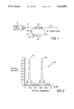
- FIG. 1 is a schematic diagram of an Erbium fiber ring laser with Fabry-Perot longitudinal mode selection
- FIG. 2 is a graph illustrating the transfer function of two Fabry-Perot cavities in series, as in the laser of FIG. 1;
- FIG. 3 is a schematic diagram of an Erbium fiber ring laser with a fiber grating for mode selection
- FIG. 4 is a schematic diagram of a linear Erbium fiber laser with a fiber grating for mode selection
- FIG. 5 is a schematic diagram of a linear Erbium fiber laser having an external grating for mode selection
- FIG. 6 is a schematic diagram of an Erbium fiber ring laser having series Fabry-Perot cavities and a fiber grating for mode selection;
- FIG. 7 is a schematic diagram of a linear compound cavity Erbium fiber laser with a pair of fiber gratings
- FIG. 8 is a schematic diagram of a linear compound cavity fiber laser having a first Fabry-Perot cavity with a second Fabry-Perot cavity at the center thereof;
- FIG. 9 is a schematic diagram of a linear compound cavity fiber laser having a Fabry-Perot cavity with a Moire grating at the center thereof.
- the present invention provides a rare earth laser with longitudinal mode selection.
- Various embodiments are illustrated. Additional embodiments will be apparent to those skilled in the art from the following description.
- a ring cavity laser comprises an Erbium doped optical fiber 14.
- the Erbium doping (gain medium) establishes the optical gain. Erbium is particularly useful for lasers operating in the 1.5 micron region, whereas Neodymium and Praseodymium is particularly useful in the 1.3 micron region.
- Laser cavity 14 is pumped by a pump laser 10 that communicates via an optical fiber 12 to a conventional coupler 26 that couples the laser cavity to an output fiber 28.
- pump laser 10 can operate at a standard 980 nm or 1480 nm wavelength.
- Optical isolator 16 is provided within the ring so that the ring will only support a traveling wave oscillation in one direction.
- the optical isolator is a commercially available type that only passes one polarization, such that undesired polarization modes are prevented from lasing. Using a single polarization allows a high finesse cavity to be realized. Bifringence is not a problem since only one polarization is excited.
- the output of optical isolator 16 is coupled via optical fiber 18 to a first mirror 20, that in turn is coupled via optical fiber 22 to a second mirror 24.
- the use of mirrors 20 and 24 results in a pair of unequal length Fabry-Perot interferometers in series to provide wavelength selectivity within the ring laser.
- a discussion of the operation of Fabry-Perot interferometers can be found in D. R. Huber and J. B. Carroll, "Time Domain Response Of An Optically Frequency Swept Fabry-Perot Interferometer", Applied Optics, 1986, Vol. 25, pp. 2386-2390.
- the concatenation of Fabry-Perot interferometers within the ring is used to select fewer longitudinal modes within the laser cavity.
- the lengths of the cavities are selected to reduce the number of modes.
- the dimension of the two cavities can be made such that only a single mode is supported. It is also possible to provide a single mode using one cavity, for example, as illustrated in FIG. 3 discussed below.
- the diameter of the ring is desirable to make the diameter of the ring as small as possible. This is due to the fact that the smaller the ring diameter, the further apart the longitudinal modes will be. Those skilled in the art will appreciate that the entire ring can be doped with Erbium, or just a portion 14 can be doped as shown in FIG. 1.
- FIG. 2 illustrates the transfer function, generally designated 30, of the two-series Fabry-Perot cavities shown in FIG. 1.
- Coinciding frequencies of the coupled cavities add, and the transfer function is the product of the frequencies within each cavity.
- the transfer function is the product of the frequencies within each cavity.
- FIG. 3 illustrates an embodiment wherein a grating structure 40 is substituted for the Fabry-Perot interferometers of FIG. 1 to provide mode selection.
- a grating structure 40 is substituted for the Fabry-Perot interferometers of FIG. 1 to provide mode selection.
- the operation of such gratings is discussed in K. L. Belsley, J. B. Carroll, L. A. Hess, D. R. Huber, and D. Schmadel, "Optically Multiplexed Interferometric Fiber Optic Sensor System", SPIE, 1985, Vol. 566, pp. 257-264 and in W. V. Sorin and S. A. Newton, "Single-Frequency Output From A Broadband-Tunable External-Fiber-Cavity Laser", OFC 1988, Vol. WQ26, pp. 123.
- the grating dimensions must be chosen to provide a single mode frequency peak having a desired wavelength within the gain curve of the Erbium laser.
- FIG. 4 illustrates a linear structure that also uses a grating to provide mode selection.
- Pump laser 10 provides the optical energy necessary to cause Erbium doped fiber 53 to lase.
- Optical fiber 53 is coupled to pump laser 10.
- Grating 54 in combination with mirror 52 defines the length of the laser cavity.
- the dimensions of grating 54 provide the desired single mode within the gain curve of the laser.
- Optical isolator 58 restricts perturbing back reflection into the laser cavity.
- the optical carrier generated by the laser is output on an optical fiber 60.
- the length of the laser cavity defines the natural resonance(s) of the cavity.
- the grating is used to select from these natural resonances.
- the linear cavity of the FIG. 4 embodiment can be constructed from a piece of Erbium doped optical fiber that incorporates a grating within the fiber.
- the linear cavity can comprise a length of undoped grating fiber coupled to an Erbium doped fiber.
- Mirror 52 can be constructed, e.g., by evaporating silver, gold, or aluminum on the fiber end, and then splicing the fiber.
- a dielectric mirror could be formed as well known in the art.
- the configuration shown in FIG. 4 is one method for making the laser run at a single frequency.
- the length of the laser cavity as determined by the reflectors 54 and 52 is short enough so that only one Fabry-Perot mode exists within the cavity. This forces the laser to run single frequency.
- a specific example of the design of such a laser follows.
- the laser can only lase within the width of the reflector.
- a typical reflector bandwidth is one angstrom.
- the mode spacing FSR (free spectral range) of a Fabry-Perot cavity is given by the formula:
- n index of refraction of fiber
- the laser cavity length (L) works out to 8.2 millimeters.
- this length is too short to be practical for a doped fiber.
- Planar silica waveguide heavily doped with Erbium and Germanium could be used to produce a micro laser.
- gratings 100 and 102 each have a reflectivity bandwidth of one angstrom and reflect at the same wavelength. Since the free spectral range of the Fabry-Perot formed by the gratings is less than the reflection bandwidth of the gratings, only one Fabry-Perot mode exists within the reflection bandwidth of the gratings.
- the cavity formed by grating 100 and mirror 104 is eighty centimeters in length. This yields an FSR of 128 MHz.
- the FSR for the eight millimeter cavity formed by gratings 100, 102 is 12.8 GHz.
- the short cavity in FIG. 7 produces fringes analogous to peaks 32 and 34 illustrated in FIG. 2.
- the more closely spaced fringes in FIG. 2 are analogous to the fringes produced by the eighty millimeter cavity.
- a finesse on the order of one hundred may be required in the Fabry-Perot formed by gratings 100, 102 to ensure proper mode selection.
- gratings 100, 102 are made narrower in bandwidth, it becomes easier to realize a laser which will select only one mode.
- the simple configuration shown in FIG. 4 may be operated at a single frequency even when the optical bandwidth of grating 54 supports more than one Fabry-Perot mode of the cavity formed by reflectors 54 and 52. This is because the Erbium laser is mostly homogeneously broadened so it attempts to self select for single frequency oscillation.
- the compound cavity design described above applies to other laser systems as well. Neodymium for operation at 1.3 microns is a good example.
- Gratings are also commercially available, for example, from United Technologies Corporation, which places gratings in fibers that have Germanium dopants. They do this by creating an interference pattern with a high power laser, e.g. at 248 nanometers. This interference pattern is used to expose the fiber, thereby locally modifying the refractive index of the fiber.
- a high power laser e.g. at 248 nanometers.
- Reflectors such as reflector 52 of FIG. 4, can comprise partially reflecting mirrors obtained, for example, by cleaving the fiber, placing a dielectric coating thereon, and then splicing the fiber back together.
- Other types of suitable reflectors are commercially available. Nearly lossless mirrors can be obtained for mirrors with reflectivities ranging from 5% to 95%.
- Optical isolators and couplers for use in connection with the present invention are also readily available.
- Pump laser 10 outputs energy on an optical fiber 70 to a coupler 72.
- a grating lens 74 is coupled to an Erbium doped fiber 76 that receives the pump laser energy via coupler 72.
- This coupler should be a wavelength selective coupler for efficient coupling of pump light into the laser cavity and to prevent light at the lasing frequency from coupling back into the pump laser.
- Mirror 78 defines the length of the Erbium fiber laser cavity.
- An optical isolator 80 limits back reflection into the fiber laser.
- Different grating lenses 74 can be coupled to the Erbium fiber to empirically establish the dimensions required for a desired application.
- FIG. 6 illustrates another ring laser embodiment that combines the Fabry-Perot interferometers of FIG. 1 with the grating of FIG. 3.
- the dimensions of grating 90 are selected in combination with the cavity lengths to obtain operation with a few longitudinal modes or even a single longitudinal mode if desired.
- the carrier produced by the laser is output via coupler 26 to an optical fiber 92.
- the location of mirrors 20, 24 define a cavity length with desired natural resonances.
- the polarization sensitivity of the standard couplers, grating(s) and optical isolator(s) may make it necessary to place a polarization controller in the ring cavity to increase finesse. Since a manual polarization controller is not practical for most applications, the solution to the problems of low finesse and polarization sensitivity (bifringence) is to construct the fiber laser with polarization maintaining fiber and to only excite one of the polarization modes. High finesse couplers useful in such embodiments are available from various vendors.
- FIG. 8 illustrates a preferred embodiment of a laser using a pair of series coupled Fabry-Perot cavities.
- a first Fabry-Perot cavity which is the same as the laser cavity, extends over a length L from a grating 110 to a reflector 116.
- a second Fabry-Perot cavity is placed at or near the center of the first Fabry-Perot cavity.
- the second Fabry-Perot cavity has a length 1 and is formed by a first reflector 112 and a second reflector 114. Reflectors 112, 114 can be formed within the waveguide using any combination of metallic, dielectric or grating structures as well known in the art.
- the second Fabry-Perot cavity can be replaced with a Moire type grating having a transmission peak at the lasing wavelength, which gratings are discussed in the article to Ragdale, et al. cited above.
- FIG. 9 is similar to the structure shown in FIG. 8 except that the locations of grating 110 and mirror 116 have been arbitrarily reversed and reflectors 112, 114 have been replaced with Moire grating 130.
- grating 110 can have, for example, a reflectivity of about 95% at the operating wavelength (e.g., 1.5 ⁇ m) of the laser. At this wavelength, reflector 116 will have a reflectivity of about 4-15%.
- the positions of grating 110 and reflector 116 defining the first Fabry-Perot cavity can be interchanged. In such an embodiment, the reflectivity of the reflector 116 adjacent pump laser 10 would be about 100% at the operating wavelength of the laser, and its transmissivity would be about 100% at the pump wavelength.
- the grating 110 when positioned next to optical isolator 118, would have a reflectivity of about 4-15% at the operating wavelength of the laser.
- the length of the first Fabry-Perot cavity L can be on the order of one meter, with the length 1 of the second Fabry-Perot cavity on the order of one millimeter.
- the free spectral range of the second Fabry-Perot cavity is slightly less than the reflection bandwidth of the grating.
- the grating restricts the laser to the bandwidth of the grating.
- the second Fabry-Perot cavity further restricts the bandwidth to the free spectral range (FSR).
- the cavity length L is chosen to be short enough so that only one Fabry-Perot mode is supported.
- the second Fabry-Perot cavity is placed near the center of the first Fabry-Perot cavity to minimize gain except at the desired lasing wavelength.
- This structure should suppress lasing in the potential undesired laser cavities that could otherwise exist between grating 110 and reflector 112 and between reflector 114 and mirror 116.
- the optimal location of the second Fabry-Perot cavity is determined by the relative lasing thresholds of the competing laser cavities between grating 110 and reflector 112 and between reflector 114 and mirror 116. If the reflectivities of grating 110 and mirror 116 are equal, then the optical placement of the second Fabry-Perot will be centered in the first Fabry-Perot cavity. If grating 110 has a higher reflectivity than mirror 116, then the second Fabry-Perot should be moved closer to grating 110 to minimize the gain of the cavity between grating 110 and reflector 112. Conversely, if mirror 116 has the higher reflectivity, the second Fabry-Perot would be placed closer to it.
- lasing in one of the two linear polarizations can be suppressed by introducing a polarization filter 120 near the center of the optical cavity.
- the structure of FIG. 8 can be implemented in a doped optical fiber or a silica waveguide.
- the present invention provides a rare earth doped laser for providing an optical carrier having at least one suppressed mode.
- the laser can be constructed with a doped optical fiber, or in any other optical transmission medium such as a silica glass substrate directly doped with the rare earth element.
- Such a structure is advantageous in that high levels of integration are obtainable.
Abstract
Description
FSR=λ.sup.2 /(2nL) where:
Claims (20)
Priority Applications (9)
| Application Number | Priority Date | Filing Date | Title |
|---|---|---|---|
| US07/770,762 US5151908A (en) | 1990-11-20 | 1991-10-09 | Laser with longitudinal mode selection |
| DE69119708T DE69119708T2 (en) | 1990-11-20 | 1991-11-13 | Longitudinal mode selection laser |
| EP91119308A EP0486930B1 (en) | 1990-11-20 | 1991-11-13 | Laser with longitudinal mode selection |
| CA002055324A CA2055324C (en) | 1990-11-20 | 1991-11-13 | Laser with longitudinal mode selection |
| NO914521A NO306089B1 (en) | 1990-11-20 | 1991-11-19 | Laser |
| MX9102129A MX9102129A (en) | 1990-11-20 | 1991-11-19 | LASER WITH SELECTION OF LONGITUDINAL MODE |
| JP33126391A JP3464804B2 (en) | 1990-11-20 | 1991-11-20 | Vertical mode selection laser |
| US07/887,090 US5243609A (en) | 1990-11-20 | 1992-05-22 | Laser with longitudinal mode selection |
| HK98106357A HK1008404A1 (en) | 1990-11-20 | 1998-06-24 | Laser with longitudinal mode selection |
Applications Claiming Priority (2)
| Application Number | Priority Date | Filing Date | Title |
|---|---|---|---|
| US07/616,024 US5134620A (en) | 1990-11-20 | 1990-11-20 | Laser with longitudinal mode selection |
| US07/770,762 US5151908A (en) | 1990-11-20 | 1991-10-09 | Laser with longitudinal mode selection |
Related Parent Applications (1)
| Application Number | Title | Priority Date | Filing Date |
|---|---|---|---|
| US07/616,024 Continuation-In-Part US5134620A (en) | 1990-11-20 | 1990-11-20 | Laser with longitudinal mode selection |
Related Child Applications (1)
| Application Number | Title | Priority Date | Filing Date |
|---|---|---|---|
| US07/887,090 Continuation-In-Part US5243609A (en) | 1990-11-20 | 1992-05-22 | Laser with longitudinal mode selection |
Publications (1)
| Publication Number | Publication Date |
|---|---|
| US5151908A true US5151908A (en) | 1992-09-29 |
Family
ID=27087656
Family Applications (1)
| Application Number | Title | Priority Date | Filing Date |
|---|---|---|---|
| US07/770,762 Expired - Lifetime US5151908A (en) | 1990-11-20 | 1991-10-09 | Laser with longitudinal mode selection |
Country Status (8)
| Country | Link |
|---|---|
| US (1) | US5151908A (en) |
| EP (1) | EP0486930B1 (en) |
| JP (1) | JP3464804B2 (en) |
| CA (1) | CA2055324C (en) |
| DE (1) | DE69119708T2 (en) |
| HK (1) | HK1008404A1 (en) |
| MX (1) | MX9102129A (en) |
| NO (1) | NO306089B1 (en) |
Cited By (44)
| Publication number | Priority date | Publication date | Assignee | Title |
|---|---|---|---|---|
| US5271024A (en) * | 1992-07-27 | 1993-12-14 | General Instrument Corporation | Optical fiber amplifier and laser with flattened gain slope |
| US5311525A (en) * | 1992-03-31 | 1994-05-10 | The Board Of Trustees Of The Leland Stanford University | Nonlinear optical coupler using a doped optical waveguide |
| US5323404A (en) * | 1993-11-02 | 1994-06-21 | At&T Bell Laboratories | Optical fiber laser or amplifier including high reflectivity gratings |
| US5448657A (en) * | 1993-04-22 | 1995-09-05 | Agency For Defense Development | Polarimetric fiber laser sensors |
| US5555118A (en) * | 1993-06-04 | 1996-09-10 | Ciena Corporation | Method for removing and inserting optical carriers in a WDM optical communication system |
| US5600473A (en) * | 1993-06-04 | 1997-02-04 | Ciena Corporation | Optical amplifier systems with add/drop multiplexing |
| US5799032A (en) * | 1994-07-06 | 1998-08-25 | Forsvarets Forskningsanstalt | Laser resonator for at least two laser modes from an optically pumped laser medium |
| US5915052A (en) * | 1997-06-30 | 1999-06-22 | Uniphase Telecommunications Products, Inc. | Loop status monitor for determining the amplitude of the signal components of a multi-wavelength optical beam |
| USH1813H (en) * | 1993-11-19 | 1999-11-02 | Kersey; Alan D. | Spectrally-selective fiber transmission filter system |
| US5982964A (en) * | 1997-06-30 | 1999-11-09 | Uniphase Corporation | Process for fabrication and independent tuning of multiple integrated optical directional couplers on a single substrate |
| US6020986A (en) * | 1997-11-21 | 2000-02-01 | Jds Uniphase Corporation | Programmable add-drop module for use in an optical circuit |
| US6031849A (en) * | 1997-11-14 | 2000-02-29 | Jds Uniphase Corporation | High power three level fiber laser and method of making same |
| US6088144A (en) * | 1996-09-13 | 2000-07-11 | Lucent Technologies Inc. | Detection of frequency-modulated tones in electromagnetic signals |
| US6151157A (en) * | 1997-06-30 | 2000-11-21 | Uniphase Telecommunications Products, Inc. | Dynamic optical amplifier |
| US6226424B1 (en) | 1997-09-19 | 2001-05-01 | Uniphase Telecommunications Products, Inc. | Integrated wavelength-select transmitter |
| US6310990B1 (en) | 2000-03-16 | 2001-10-30 | Cidra Corporation | Tunable optical structure featuring feedback control |
| US6330388B1 (en) | 1999-01-27 | 2001-12-11 | Northstar Photonics, Inc. | Method and apparatus for waveguide optics and devices |
| US6335820B1 (en) | 1999-12-23 | 2002-01-01 | Xtera Communications, Inc. | Multi-stage optical amplifier and broadband communication system |
| US6356384B1 (en) | 1998-03-24 | 2002-03-12 | Xtera Communications Inc. | Broadband amplifier and communication system |
| US6359725B1 (en) | 1998-06-16 | 2002-03-19 | Xtera Communications, Inc. | Multi-stage optical amplifier and broadband communication system |
| US6370164B1 (en) | 1996-12-23 | 2002-04-09 | Xtera Communications, Inc. | Broadband sagnac raman amplifiers and cascade lasers |
| US6374006B1 (en) | 1998-03-20 | 2002-04-16 | Xtera Communications, Inc. | Chirped period gratings for raman amplification in circulator loop cavities |
| US20020085270A1 (en) * | 2000-11-27 | 2002-07-04 | Bendett Mark P. | Apparatus and method for integrated photonic devices having add/drop ports and gain |
| US6480513B1 (en) | 2000-10-03 | 2002-11-12 | K2 Optronics, Inc. | Tunable external cavity laser |
| US6567430B1 (en) | 1998-09-21 | 2003-05-20 | Xtera Communications, Inc. | Raman oscillator including an intracavity filter and amplifiers utilizing same |
| US6574037B2 (en) | 1998-06-16 | 2003-06-03 | Xtera Communications, Inc. | All band amplifier |
| US6600592B2 (en) | 1998-03-24 | 2003-07-29 | Xtera Communications, Inc. | S+ band nonlinear polarization amplifiers |
| US20030185514A1 (en) * | 2002-03-29 | 2003-10-02 | Bendett Mark P. | Method and apparatus for tapping a waveguide on a substrate |
| US6631025B2 (en) | 2000-01-12 | 2003-10-07 | Xtera Communications, Inc. | Low-noise distributed Raman amplifier using bi-directional pumping using multiple Raman orders |
| US20030196455A1 (en) * | 2002-04-17 | 2003-10-23 | Mccov Michael A. | Apparatus and method for photonic waveguide fabrication |
| US20040028091A1 (en) * | 2000-06-20 | 2004-02-12 | Valeri Baev | Fiber laser |
| US6693737B2 (en) | 1998-03-24 | 2004-02-17 | Xtera Communications, Inc. | Dispersion compensating nonlinear polarization amplifiers |
| US6760509B2 (en) | 2000-02-14 | 2004-07-06 | The Regents Of The University Of Michigan | SNR booster for WDM systems |
| US6760148B2 (en) | 1998-03-24 | 2004-07-06 | Xtera Communications, Inc. | Nonlinear polarization amplifiers in nonzero dispersion shifted fiber |
| US20040208579A1 (en) * | 2002-03-29 | 2004-10-21 | Bendett Mark P. | Compact apparatus and method for integrated photonic devices having folded directional couplers |
| US20040246567A1 (en) * | 2003-06-09 | 2004-12-09 | Joon Tae Ahn | Gain-clamped optical amplifier |
| US6885498B2 (en) | 1998-06-16 | 2005-04-26 | Xtera Communications, Inc. | Multi-stage optical amplifier and broadband communication system |
| US20050185262A1 (en) * | 2003-12-18 | 2005-08-25 | In-Kuk Yun | Broadband light source |
| US6985283B1 (en) | 1998-06-16 | 2006-01-10 | Xtera Communications, Inc. | Fiber-optic compensation for dispersion, gain tilt, and band pump nonlinearity |
| US20090067188A1 (en) * | 2006-03-31 | 2009-03-12 | The Furukawa Electric Co., Ltd. | Light source |
| US20100195682A1 (en) * | 2008-06-19 | 2010-08-05 | Koji Nonaka | Laser pulse generating apparatus and method |
| CN102148472A (en) * | 2011-03-14 | 2011-08-10 | 苏州华必大激光有限公司 | Moire effect-based wavelength-tunable hybrid laser |
| US20140098412A1 (en) * | 2012-10-05 | 2014-04-10 | Volcano Corporation | Systems and methods for amplifying light |
| US20140198377A1 (en) * | 2013-01-15 | 2014-07-17 | Omron Corporation | Laser oscillator |
Families Citing this family (11)
| Publication number | Priority date | Publication date | Assignee | Title |
|---|---|---|---|---|
| US5243609A (en) * | 1990-11-20 | 1993-09-07 | General Instrument Corporation | Laser with longitudinal mode selection |
| US5132976A (en) * | 1991-05-28 | 1992-07-21 | At&T Bell Laboratories | Electrically tunable fiber ring laser |
| US5434876A (en) * | 1992-10-23 | 1995-07-18 | At&T Bell Laboratories | Article comprising an optical waveguide laser |
| US5473622A (en) * | 1994-12-29 | 1995-12-05 | At&T Corp. | Cladding-pumped MOPA structure |
| US5546481A (en) * | 1995-03-02 | 1996-08-13 | United Technologies Corporation | Single polarization fiber and amplifier |
| US5511083A (en) * | 1995-03-02 | 1996-04-23 | United Technologies Corporation | Polarized fiber laser source |
| DE19730830A1 (en) * | 1997-07-18 | 1999-01-21 | Alsthom Cge Alcatel | Laser for generating a wave crest |
| AUPO998997A0 (en) * | 1997-10-24 | 1997-11-20 | University Of Sydney, The | Brillouin/erbium fibre laser current monitor using elliptically polarizing fibre |
| US6498799B1 (en) * | 1999-08-12 | 2002-12-24 | California Institute Of Technology | Single-mode fiber ring laser |
| WO2011016419A1 (en) * | 2009-08-03 | 2011-02-10 | 旭硝子株式会社 | Fiber laser |
| JP2012164860A (en) * | 2011-02-08 | 2012-08-30 | Fujikura Ltd | Q switch type fiber laser |
Citations (10)
| Publication number | Priority date | Publication date | Assignee | Title |
|---|---|---|---|---|
| US3958188A (en) * | 1974-12-11 | 1976-05-18 | Nasa | Fiber distributed feedback laser |
| US4358851A (en) * | 1980-02-28 | 1982-11-09 | Xerox Corporation | Fiber optic laser device and light emitter utilizing the device |
| US4530097A (en) * | 1982-09-29 | 1985-07-16 | The Board Of Trustees Of The Leland Stanford Junior University | Brillouin ring laser |
| US4564949A (en) * | 1982-12-13 | 1986-01-14 | Spectron Development Laboratories | Folded cavity laser for holography |
| US4734912A (en) * | 1986-06-06 | 1988-03-29 | Lightwave Electronics Corp. | Laser diode end pumped Nd:YAG single mode laser |
| US4734380A (en) * | 1983-04-08 | 1988-03-29 | American Telephone And Telegraph Company, At&T Bell Laboratories | Multicavity optical device held together by metallic film |
| US4794615A (en) * | 1987-06-12 | 1988-12-27 | Spectra Diode Laboratories, Inc. | End and side pumped laser |
| US4805185A (en) * | 1986-03-04 | 1989-02-14 | The United States Of America As Represented By The Secretary Of The Air Force | Triple cavity laser |
| US4901322A (en) * | 1988-07-01 | 1990-02-13 | Spectra-Physics, Inc. | Tunable pulsed single longitudinal mode laser oscillator |
| US4963832A (en) * | 1989-08-08 | 1990-10-16 | At&T Bell Laboratories | Erbium-doped fiber amplifier coupling device |
Family Cites Families (4)
| Publication number | Priority date | Publication date | Assignee | Title |
|---|---|---|---|---|
| FR1554864A (en) * | 1967-12-11 | 1969-01-24 | ||
| US3609586A (en) * | 1969-06-18 | 1971-09-28 | Bell Telephone Labor Inc | Laser with pulsed transmission mode q-switching |
| AU584739B2 (en) * | 1985-08-13 | 1989-06-01 | British Technology Group Limited | Optical fibres |
| JP2605023B2 (en) * | 1986-10-07 | 1997-04-30 | 富士通株式会社 | Fiber laser |
-
1991
- 1991-10-09 US US07/770,762 patent/US5151908A/en not_active Expired - Lifetime
- 1991-11-13 EP EP91119308A patent/EP0486930B1/en not_active Expired - Lifetime
- 1991-11-13 CA CA002055324A patent/CA2055324C/en not_active Expired - Lifetime
- 1991-11-13 DE DE69119708T patent/DE69119708T2/en not_active Expired - Fee Related
- 1991-11-19 MX MX9102129A patent/MX9102129A/en unknown
- 1991-11-19 NO NO914521A patent/NO306089B1/en not_active IP Right Cessation
- 1991-11-20 JP JP33126391A patent/JP3464804B2/en not_active Expired - Fee Related
-
1998
- 1998-06-24 HK HK98106357A patent/HK1008404A1/en not_active IP Right Cessation
Patent Citations (10)
| Publication number | Priority date | Publication date | Assignee | Title |
|---|---|---|---|---|
| US3958188A (en) * | 1974-12-11 | 1976-05-18 | Nasa | Fiber distributed feedback laser |
| US4358851A (en) * | 1980-02-28 | 1982-11-09 | Xerox Corporation | Fiber optic laser device and light emitter utilizing the device |
| US4530097A (en) * | 1982-09-29 | 1985-07-16 | The Board Of Trustees Of The Leland Stanford Junior University | Brillouin ring laser |
| US4564949A (en) * | 1982-12-13 | 1986-01-14 | Spectron Development Laboratories | Folded cavity laser for holography |
| US4734380A (en) * | 1983-04-08 | 1988-03-29 | American Telephone And Telegraph Company, At&T Bell Laboratories | Multicavity optical device held together by metallic film |
| US4805185A (en) * | 1986-03-04 | 1989-02-14 | The United States Of America As Represented By The Secretary Of The Air Force | Triple cavity laser |
| US4734912A (en) * | 1986-06-06 | 1988-03-29 | Lightwave Electronics Corp. | Laser diode end pumped Nd:YAG single mode laser |
| US4794615A (en) * | 1987-06-12 | 1988-12-27 | Spectra Diode Laboratories, Inc. | End and side pumped laser |
| US4901322A (en) * | 1988-07-01 | 1990-02-13 | Spectra-Physics, Inc. | Tunable pulsed single longitudinal mode laser oscillator |
| US4963832A (en) * | 1989-08-08 | 1990-10-16 | At&T Bell Laboratories | Erbium-doped fiber amplifier coupling device |
Non-Patent Citations (20)
| Title |
|---|
| Catherine M. Ragdale, et al., "Narrowband Fiber Grating Filters," IEEE Journal on Selected Areas in Communications, 1990, vol. 8, pp. 1146-1150. |
| Catherine M. Ragdale, et al., Narrowband Fiber Grating Filters, IEEE Journal on Selected Areas in Communications, 1990, vol. 8, pp. 1146 1150. * |
| David R. Huber, et al., "Time Domain Response of an Optically Frequency Swept Fabry-Perot Interferometer," Applied Optics, 1986, vol. 25, pp. 2386-2390. |
| David R. Huber, et al., Time Domain Response of an Optically Frequency Swept Fabry Perot Interferometer, Applied Optics, 1986, vol. 25, pp. 2386 2390. * |
| G. Ball, et al., "Tunable Er3+ Fiber Laser Utilizing Intracore Bragg Reflectors," OFC 91, Feb., 1991, Paper FA4, p. 196. |
| G. Ball, et al., Tunable Er 3 Fiber Laser Utilizing Intracore Bragg Reflectors, OFC 91, Feb., 1991, Paper FA4, p. 196. * |
| G. Meltz, et al., "Formation of Bragg Gratings in Optical Fibers by a Transverse Holographic Method,"Optics Letters, 1989, vol. 14, pp. 823-825. |
| G. Meltz, et al., Formation of Bragg Gratings in Optical Fibers by a Transverse Holographic Method, Optics Letters, 1989, vol. 14, pp. 823 825. * |
| Gary Ball, "Fiber Laser Incorporating Internal Bragg Reflectors," LEOS '90 IEEE Lasers and Electro-Optics Society Annual Meeting, Nov. 4-9, 1990, p. 50. |
| Gary Ball, Fiber Laser Incorporating Internal Bragg Reflectors, LEOS 90 IEEE Lasers and Electro Optics Society Annual Meeting, Nov. 4 9, 1990, p. 50. * |
| H. Okamura, et al., "Spectral Linewidth Broadening in Er-Doped-Fibre Amplifiers Measured with Less than 1.4 kHz Linewidth Light Source," Electronics Letters, 1990, vol. 26, pp. 1965-1967. |
| H. Okamura, et al., Spectral Linewidth Broadening in Er Doped Fibre Amplifiers Measured with Less than 1.4 kHz Linewidth Light Source, Electronics Letters, 1990, vol. 26, pp. 1965 1967. * |
| K. Iwatsuki, et al., "Wavelength-Tunable Single-Frequency and Single-Polarisation Er-Doped Fibre Ring-Laser with 1.4 kHz Linewidth," Electronics Letters, 1990, vol. 26, pp. 2033-2035. |
| K. Iwatsuki, et al., Wavelength Tunable Single Frequency and Single Polarisation Er Doped Fibre Ring Laser with 1.4 kHz Linewidth, Electronics Letters, 1990, vol. 26, pp. 2033 2035. * |
| K. L. Belsley, et al., "Optically Multiplexed Interferometric Fiber Optic Sensor System," SPIE, 1985, vol. 566, pp. 257-264. |
| K. L. Belsley, et al., Optically Multiplexed Interferometric Fiber Optic Sensor System, SPIE, 1985, vol. 566, pp. 257 264. * |
| M. W. Maeda, et al., "Continuous Acousto-Optic Tuning of an Erbium-Doped Fiber Laser at 1.5 um," LEOS '90 IEEE Lasers and Electro-Optics Society Annual Meeting, Nov. 4-9, 1990, p. 48. |
| M. W. Maeda, et al., Continuous Acousto Optic Tuning of an Erbium Doped Fiber Laser at 1.5 um, LEOS 90 IEEE Lasers and Electro Optics Society Annual Meeting, Nov. 4 9, 1990, p. 48. * |
| Wayne V. Sorin, et al., "Single-Frequency Output from a Broadband-Tunable External-Fiber-Cavity Laser," OFC 1988, vol. WQ26, p. 123. |
| Wayne V. Sorin, et al., Single Frequency Output from a Broadband Tunable External Fiber Cavity Laser, OFC 1988, vol. WQ26, p. 123. * |
Cited By (63)
| Publication number | Priority date | Publication date | Assignee | Title |
|---|---|---|---|---|
| US5311525A (en) * | 1992-03-31 | 1994-05-10 | The Board Of Trustees Of The Leland Stanford University | Nonlinear optical coupler using a doped optical waveguide |
| US5271024A (en) * | 1992-07-27 | 1993-12-14 | General Instrument Corporation | Optical fiber amplifier and laser with flattened gain slope |
| US5448657A (en) * | 1993-04-22 | 1995-09-05 | Agency For Defense Development | Polarimetric fiber laser sensors |
| US5555118A (en) * | 1993-06-04 | 1996-09-10 | Ciena Corporation | Method for removing and inserting optical carriers in a WDM optical communication system |
| US5579143A (en) * | 1993-06-04 | 1996-11-26 | Ciena Corporation | Optical system with tunable in-fiber gratings |
| US5600473A (en) * | 1993-06-04 | 1997-02-04 | Ciena Corporation | Optical amplifier systems with add/drop multiplexing |
| US5701186A (en) * | 1993-06-04 | 1997-12-23 | Ciena Corporation | Optical cable TV system |
| US5323404A (en) * | 1993-11-02 | 1994-06-21 | At&T Bell Laboratories | Optical fiber laser or amplifier including high reflectivity gratings |
| USH1813H (en) * | 1993-11-19 | 1999-11-02 | Kersey; Alan D. | Spectrally-selective fiber transmission filter system |
| US5799032A (en) * | 1994-07-06 | 1998-08-25 | Forsvarets Forskningsanstalt | Laser resonator for at least two laser modes from an optically pumped laser medium |
| US6088144A (en) * | 1996-09-13 | 2000-07-11 | Lucent Technologies Inc. | Detection of frequency-modulated tones in electromagnetic signals |
| US6833946B2 (en) | 1996-12-23 | 2004-12-21 | Xtera Communications, Inc. | Optical amplification using polarization diversity pumping |
| US6370164B1 (en) | 1996-12-23 | 2002-04-09 | Xtera Communications, Inc. | Broadband sagnac raman amplifiers and cascade lasers |
| US5915052A (en) * | 1997-06-30 | 1999-06-22 | Uniphase Telecommunications Products, Inc. | Loop status monitor for determining the amplitude of the signal components of a multi-wavelength optical beam |
| US5982964A (en) * | 1997-06-30 | 1999-11-09 | Uniphase Corporation | Process for fabrication and independent tuning of multiple integrated optical directional couplers on a single substrate |
| US6151157A (en) * | 1997-06-30 | 2000-11-21 | Uniphase Telecommunications Products, Inc. | Dynamic optical amplifier |
| US6370290B1 (en) | 1997-09-19 | 2002-04-09 | Uniphase Corporation | Integrated wavelength-select transmitter |
| US6226424B1 (en) | 1997-09-19 | 2001-05-01 | Uniphase Telecommunications Products, Inc. | Integrated wavelength-select transmitter |
| US6031849A (en) * | 1997-11-14 | 2000-02-29 | Jds Uniphase Corporation | High power three level fiber laser and method of making same |
| US6020986A (en) * | 1997-11-21 | 2000-02-01 | Jds Uniphase Corporation | Programmable add-drop module for use in an optical circuit |
| US6374006B1 (en) | 1998-03-20 | 2002-04-16 | Xtera Communications, Inc. | Chirped period gratings for raman amplification in circulator loop cavities |
| US6356384B1 (en) | 1998-03-24 | 2002-03-12 | Xtera Communications Inc. | Broadband amplifier and communication system |
| US6693738B2 (en) | 1998-03-24 | 2004-02-17 | The Regents Of The University Of Michigan | Broadband amplifier and communication system |
| US6693737B2 (en) | 1998-03-24 | 2004-02-17 | Xtera Communications, Inc. | Dispersion compensating nonlinear polarization amplifiers |
| US6760148B2 (en) | 1998-03-24 | 2004-07-06 | Xtera Communications, Inc. | Nonlinear polarization amplifiers in nonzero dispersion shifted fiber |
| US6600592B2 (en) | 1998-03-24 | 2003-07-29 | Xtera Communications, Inc. | S+ band nonlinear polarization amplifiers |
| US6580548B2 (en) | 1998-03-24 | 2003-06-17 | Xtera Communications, Inc. | Broadband amplifier and communication system |
| US6574037B2 (en) | 1998-06-16 | 2003-06-03 | Xtera Communications, Inc. | All band amplifier |
| US6885498B2 (en) | 1998-06-16 | 2005-04-26 | Xtera Communications, Inc. | Multi-stage optical amplifier and broadband communication system |
| US6359725B1 (en) | 1998-06-16 | 2002-03-19 | Xtera Communications, Inc. | Multi-stage optical amplifier and broadband communication system |
| US6985283B1 (en) | 1998-06-16 | 2006-01-10 | Xtera Communications, Inc. | Fiber-optic compensation for dispersion, gain tilt, and band pump nonlinearity |
| US6567430B1 (en) | 1998-09-21 | 2003-05-20 | Xtera Communications, Inc. | Raman oscillator including an intracavity filter and amplifiers utilizing same |
| US6690873B2 (en) | 1999-01-27 | 2004-02-10 | Teem Photonics | Method and apparatus for waveguide optics and devices |
| US6970494B1 (en) | 1999-01-27 | 2005-11-29 | Teem Photonics, S.A. | Rare-earth doped phosphate-glass lasers and associated methods |
| US6330388B1 (en) | 1999-01-27 | 2001-12-11 | Northstar Photonics, Inc. | Method and apparatus for waveguide optics and devices |
| US6636678B1 (en) | 1999-01-27 | 2003-10-21 | Teem Photonics, Inc. | Method and apparatus for waveguide optics and devices |
| US6335820B1 (en) | 1999-12-23 | 2002-01-01 | Xtera Communications, Inc. | Multi-stage optical amplifier and broadband communication system |
| US6631025B2 (en) | 2000-01-12 | 2003-10-07 | Xtera Communications, Inc. | Low-noise distributed Raman amplifier using bi-directional pumping using multiple Raman orders |
| US6714342B2 (en) | 2000-01-12 | 2004-03-30 | Xtera Communications, Inc. | Low-noise distributed Raman amplifier using bi-directional pumping using multiple Raman orders |
| US6760509B2 (en) | 2000-02-14 | 2004-07-06 | The Regents Of The University Of Michigan | SNR booster for WDM systems |
| US6563968B2 (en) | 2000-03-16 | 2003-05-13 | Cidra Corporation | Tunable optical structure featuring feedback control |
| US6310990B1 (en) | 2000-03-16 | 2001-10-30 | Cidra Corporation | Tunable optical structure featuring feedback control |
| US6919986B2 (en) | 2000-05-05 | 2005-07-19 | Xtera Communications, Inc. | Nonlinear polarization amplifiers in nonzero dispersion shifted fiber |
| US7027467B2 (en) * | 2000-06-20 | 2006-04-11 | Evotec Technologies Gmbh | Fiber laser |
| US20040028091A1 (en) * | 2000-06-20 | 2004-02-12 | Valeri Baev | Fiber laser |
| US6480513B1 (en) | 2000-10-03 | 2002-11-12 | K2 Optronics, Inc. | Tunable external cavity laser |
| US20020085270A1 (en) * | 2000-11-27 | 2002-07-04 | Bendett Mark P. | Apparatus and method for integrated photonic devices having add/drop ports and gain |
| US6954564B2 (en) | 2000-11-27 | 2005-10-11 | Teem Photonics | Apparatus and method for integrated photonic devices having high-performance waveguides and multicompositional substrates |
| US6493476B2 (en) | 2000-11-27 | 2002-12-10 | Teem Photonics | Apparatus and method for integrated photonic devices having gain and wavelength-selectivity |
| US20040208579A1 (en) * | 2002-03-29 | 2004-10-21 | Bendett Mark P. | Compact apparatus and method for integrated photonic devices having folded directional couplers |
| US6813405B1 (en) | 2002-03-29 | 2004-11-02 | Teem Photonics | Compact apparatus and method for integrated photonic devices having folded directional couplers |
| US20030185514A1 (en) * | 2002-03-29 | 2003-10-02 | Bendett Mark P. | Method and apparatus for tapping a waveguide on a substrate |
| US20030196455A1 (en) * | 2002-04-17 | 2003-10-23 | Mccov Michael A. | Apparatus and method for photonic waveguide fabrication |
| US20040246567A1 (en) * | 2003-06-09 | 2004-12-09 | Joon Tae Ahn | Gain-clamped optical amplifier |
| US20050185262A1 (en) * | 2003-12-18 | 2005-08-25 | In-Kuk Yun | Broadband light source |
| US7236295B2 (en) * | 2003-12-18 | 2007-06-26 | Samsung Electronics Co., Ltd. | Broadband light source |
| US20090067188A1 (en) * | 2006-03-31 | 2009-03-12 | The Furukawa Electric Co., Ltd. | Light source |
| US20100195682A1 (en) * | 2008-06-19 | 2010-08-05 | Koji Nonaka | Laser pulse generating apparatus and method |
| US8073018B2 (en) * | 2008-06-19 | 2011-12-06 | Kochi University Of Technology | Laser pulse generating apparatus and method |
| CN102148472A (en) * | 2011-03-14 | 2011-08-10 | 苏州华必大激光有限公司 | Moire effect-based wavelength-tunable hybrid laser |
| US20140098412A1 (en) * | 2012-10-05 | 2014-04-10 | Volcano Corporation | Systems and methods for amplifying light |
| US9478940B2 (en) * | 2012-10-05 | 2016-10-25 | Volcano Corporation | Systems and methods for amplifying light |
| US20140198377A1 (en) * | 2013-01-15 | 2014-07-17 | Omron Corporation | Laser oscillator |
Also Published As
| Publication number | Publication date |
|---|---|
| EP0486930A2 (en) | 1992-05-27 |
| JP3464804B2 (en) | 2003-11-10 |
| NO914521L (en) | 1992-05-21 |
| NO914521D0 (en) | 1991-11-19 |
| EP0486930B1 (en) | 1996-05-22 |
| CA2055324A1 (en) | 1992-05-21 |
| DE69119708T2 (en) | 1996-12-05 |
| MX9102129A (en) | 1992-07-08 |
| CA2055324C (en) | 1998-04-21 |
| EP0486930A3 (en) | 1993-02-24 |
| DE69119708D1 (en) | 1996-06-27 |
| HK1008404A1 (en) | 1999-05-07 |
| JPH04287384A (en) | 1992-10-12 |
| NO306089B1 (en) | 1999-09-13 |
Similar Documents
| Publication | Publication Date | Title |
|---|---|---|
| US5151908A (en) | Laser with longitudinal mode selection | |
| US5134620A (en) | Laser with longitudinal mode selection | |
| US5243609A (en) | Laser with longitudinal mode selection | |
| US6374006B1 (en) | Chirped period gratings for raman amplification in circulator loop cavities | |
| EP0651479B1 (en) | Apparatus comprising an optical fiber laser or amplifier | |
| US6370164B1 (en) | Broadband sagnac raman amplifiers and cascade lasers | |
| US7006550B2 (en) | Traveling-wave lasers with a linear cavity | |
| US6433920B1 (en) | Raman-based utility optical amplifier | |
| USH1813H (en) | Spectrally-selective fiber transmission filter system | |
| JP2000075150A (en) | Article including cascaded raman resonator of optical fiber | |
| JP4063908B2 (en) | Light source device, optical amplifier, and optical communication system | |
| US7394837B2 (en) | Traveling-wave linear cavity laser | |
| KR100448743B1 (en) | Distributed feedback ring laser | |
| JP3760129B2 (en) | Single mode fiber ring laser | |
| EP1087479A1 (en) | Stabilized laser source | |
| KR100317575B1 (en) | Wavelength-Tunable Single-Frequency Laser | |
| WO1999027619A2 (en) | Multi-mode fiber lasers | |
| GB2197747A (en) | Optical resonating device | |
| Lit | Recent advances in fiber lasers | |
| JPH0582881A (en) | Variable wave length optical fiber laser | |
| JPH08293638A (en) | Multiple-wavelength light source | |
| JPH10206662A (en) | Optical fiber laser |
Legal Events
| Date | Code | Title | Description |
|---|---|---|---|
| AS | Assignment |
Owner name: GENERAL INSTRUMENT CORPORATION, PENNSYLVANIA Free format text: ASSIGNMENT OF ASSIGNORS INTEREST.;ASSIGNOR:HUBER, DAVID R.;REEL/FRAME:005871/0556 Effective date: 19911007 |
|
| STCF | Information on status: patent grant |
Free format text: PATENTED CASE |
|
| FEPP | Fee payment procedure |
Free format text: PAYOR NUMBER ASSIGNED (ORIGINAL EVENT CODE: ASPN); ENTITY STATUS OF PATENT OWNER: LARGE ENTITY |
|
| FPAY | Fee payment |
Year of fee payment: 4 |
|
| AS | Assignment |
Owner name: GENERAL INSTRUMENT CORPORATION (GIC-4), PENNSYLVAN Free format text: ASSIGNMENT OF ASSIGNORS INTEREST;ASSIGNOR:GENERAL INSTRUMENT CORPORATION (GIC-2);REEL/FRAME:009187/0956 Effective date: 19980414 |
|
| AS | Assignment |
Owner name: GENERAL INSTRUMENT EQUITY CORPORATION, DELAWARE Free format text: CONFIRMATION OF PRIOR ASSIGNMENT OF ASSIGNOR'S ONE-HALF INTEREST IN THE PATENTS LISTED ON SCHEDULE B TO CIENA CORPORATION AND ASSIGNMENT OF ASSIGNOR'S REMAINING ONE-HALF INTEREST IN THE PATENTS LISTED ON THE ATTACHED SCHEDULE B TO GENERAL INSTRUMENT EQUITY CORPORATION.;ASSIGNOR:GENERAL INSTRUMENT CORPORATION;REEL/FRAME:009731/0359 Effective date: 19990125 Owner name: CIENA CORPORATION, MARYLAND Free format text: CONFIRMATION OF PRIOR ASSIGNMENT OF ASSIGNOR'S ONE-HALF INTEREST IN THE PATENTS LISTED ON SCHEDULE B TO CIENA CORPORATION AND ASSIGNMENT OF ASSIGNOR'S REMAINING ONE-HALF INTEREST IN THE PATENTS LISTED ON THE ATTACHED SCHEDULE B TO GENERAL INSTRUMENT EQUITY CORPORATION.;ASSIGNOR:GENERAL INSTRUMENT CORPORATION;REEL/FRAME:009731/0359 Effective date: 19990125 |
|
| FPAY | Fee payment |
Year of fee payment: 8 |
|
| AS | Assignment |
Owner name: CIENA PROPERTIES, INC., DELAWARE Free format text: ASSIGNMENT OF ASSIGNORS INTEREST;ASSIGNOR:CIENA CORPORATION;REEL/FRAME:013578/0374 Effective date: 19970401 |
|
| AS | Assignment |
Owner name: CIENA CORPORATION, MARYLAND Free format text: CO-OWNERSHIP AGREEMENT;ASSIGNOR:GENERAL INSTRUMENTS CORPORATION;REEL/FRAME:013634/0069 Effective date: 19970310 Owner name: GENERAL INSTRUMENTS CORPORATION, ILLINOIS Free format text: CO-OWNERSHIP AGREEMENT;ASSIGNOR:GENERAL INSTRUMENTS CORPORATION;REEL/FRAME:013634/0069 Effective date: 19970310 |
|
| FPAY | Fee payment |
Year of fee payment: 12 |
|
| AS | Assignment |
Owner name: CIENA CORPORATION, MARYLAND Free format text: MERGER;ASSIGNOR:CIENA PROPERTIES;REEL/FRAME:016069/0435 Effective date: 20041029 |
|
| AS | Assignment |
Owner name: LEVEL 3 COMMUNICATIONS, LLC, COLORADO Free format text: ASSIGNMENT OF ASSIGNORS INTEREST;ASSIGNOR:BROADWING, LLC;REEL/FRAME:026533/0440 Effective date: 20110630 |