US5158564A - Atherectomy apparatus - Google Patents
Atherectomy apparatus Download PDFInfo
- Publication number
- US5158564A US5158564A US07/551,013 US55101390A US5158564A US 5158564 A US5158564 A US 5158564A US 55101390 A US55101390 A US 55101390A US 5158564 A US5158564 A US 5158564A
- Authority
- US
- United States
- Prior art keywords
- wire
- rotary
- catheter
- sleeve
- hollow
- Prior art date
- Legal status (The legal status is an assumption and is not a legal conclusion. Google has not performed a legal analysis and makes no representation as to the accuracy of the status listed.)
- Expired - Fee Related
Links
Images
Classifications
-
- A—HUMAN NECESSITIES
- A61—MEDICAL OR VETERINARY SCIENCE; HYGIENE
- A61B—DIAGNOSIS; SURGERY; IDENTIFICATION
- A61B17/00—Surgical instruments, devices or methods, e.g. tourniquets
- A61B17/32—Surgical cutting instruments
- A61B17/3205—Excision instruments
- A61B17/3207—Atherectomy devices working by cutting or abrading; Similar devices specially adapted for non-vascular obstructions
- A61B17/320725—Atherectomy devices working by cutting or abrading; Similar devices specially adapted for non-vascular obstructions with radially expandable cutting or abrading elements
-
- A—HUMAN NECESSITIES
- A61—MEDICAL OR VETERINARY SCIENCE; HYGIENE
- A61B—DIAGNOSIS; SURGERY; IDENTIFICATION
- A61B17/00—Surgical instruments, devices or methods, e.g. tourniquets
- A61B17/22—Implements for squeezing-off ulcers or the like on the inside of inner organs of the body; Implements for scraping-out cavities of body organs, e.g. bones; Calculus removers; Calculus smashing apparatus; Apparatus for removing obstructions in blood vessels, not otherwise provided for
- A61B2017/22038—Implements for squeezing-off ulcers or the like on the inside of inner organs of the body; Implements for scraping-out cavities of body organs, e.g. bones; Calculus removers; Calculus smashing apparatus; Apparatus for removing obstructions in blood vessels, not otherwise provided for with a guide wire
- A61B2017/22042—Details of the tip of the guide wire
- A61B2017/22044—Details of the tip of the guide wire with a pointed tip
Definitions
- the invention relates to an atherectomy apparatus with at least one rotary member for removing deposits, coatings, occlusions, ect. in a vessel.
- An atherectomy apparatus which has, at the proximal end of a driving shaft constructed as a helically wound wire, two cutting blades directed conically towards one another.
- proximal the end of the inventive apparatus towards the heart or a part thereof is referred to as proximal and the part directed towards the surgeon or doctor as distal.
- the distal area of the cutting edges has a considerable diameter as a result of the conical tapering towards the proximal end and the shaft has a corresponding diameter.
- the catheter must have an even larger diameter.
- the canal to be created through a stenosis or a closure in a vessel to be created with the known apparatus determines the size of the puncture point for inserting the apparatus, which must have a much larger cross-section than the canal to be exposed in the vessel.
- the shaft formed by the helical winding of a wire is difficult to seal as a result of its thickness, so that blood can pass out of the vessel and out of the apparatus at the distal end. In the case of stronger clamping of a sealing valve, the friction is increased to such an extent that the driving shaft can be damaged.
- the aim underlying the invention essentially resides in providing an improved atherectomy apparatus while obviating the aforementioned disadvantages.
- Another object of the invention is to safely move abraded parts of occlusion towards the catheter orifice, so that they can be reliably suctioned off by an applied vacuum.
- an athetectomy apparatus is characterized in that the rotary member is radially expandable or spreadable from a paraxial position.
- the cutting edge or edges extend substantially axially in the paraxial position.
- the members can fundamentally be placed outwards in their cutting or operating position by a spreading member.
- the widening process of the vasoconstriction is carried out from the proximal end thereof and the members and initially moved in the contracted apparatus through a conventionally formed canal before they are radially expanded.
- the same procedure can be carried out, but is not necessary, in a construction in which the end areas of the members can be axially moved towards one another.
- the members are constructed in an elastically flexible manner and are radially expanded in that with axial spacing points located on in each case one member are axially moved towards one another, so that the preferably wire-like members are bend radially outwards.
- This construction has the advantage that there are no outwardly extending free faces or ends of the members.
- the axial fixing of the members is brought about in that the members are constructed on support parts, which are held together with the spacing of reciprocally arranged joining points and the latter are axially movable towards one another.
- the members preferably have cutting edges or knives formed by grinding. The cutting edges are essentially directed in the tangential direction of a solid of revolution formed by the wire parts. Fixing can take place in that a taut wire is passed through the joining points and, as a result, the the joining points can be drawn towards one another.
- the wire parts can be held together by sleeves in the vicinity of the joining points.
- the expandable members are connected at the distal end with a helically wound hollow wire and at the proximal end the members or wire portions are followed by the helically wound hollow wire attachment.
- the distal hollow wire forms a driving shaft for the rotation of the cutting edges.
- the expandable members or wire parts on which are optionally formed cutting edges are constructed separate from the hollow wire portions and can be fixed thereto in an appropriate manner, e.g. by soldering, clamping, etc., according to a preferred development the members or wire portions are constructed in one piece with the hollow wire parts.
- the hollow wire attachment arranged in proximal with respect to the members, prior to the widening of the vascular lumen, contributes to creating a recanalization, in order to be able to carry out the widening and removal process by the members from the proximal end of the stenosis.
- the taut wire projects at the proximal end over the members or individual wires and to its projecting end is fixed a widened abutment to counteract a tensile force exerted at the distal end and the abutment is constructed as a ball or sphere, then, by pulling on the taut wire, in the distal direction the abutment can transfer the tensile force to the proximal joining or connecting area of the individual wires optionally carrying cutting edges.
- said connecting area can be drawn towards the distal connecting area of the individual wires, so that the latter can be positioned radially towards the outside, optionally with their cutting edges.
- the inventive apparatus can be used for this purpose, so that it is possible to avoid repeatedly inserting and removing different instruments through the guidance catheter.
- the ball formed by the taut wire extending through the proximal hollow wire portion or, in more general terms, an abutment is provided with cutting parts.
- the latter can be formed by diamond chips applied to the ball, but cutting edges milled out from the same or a cutting foil fixed thereto.
- the taut wire is constructed as a hollow wire and its cavity optionally extends through the abutment.
- the apparatus or expandable members is constructed in a forceps-like manner. This gives a particularly simple construction if the cutting edges are the partly ground axial edges of the forceps jaws.
- the invention further provides a drive for an apparatus for removing deposits, such as occlusions in vessels or the like, with a device for receiving the start of an elongated, hollow guide part, such as a catheter, and with a rotary connecting part to the rotary drive of devices for removing deposits upstream of the proximal end of the guide part, which is characterized in that the connecting part can be moved backwards and forwards in the axial direction relative to the guide part receptacle.
- the working instruments driven by the drive can be constructed in different ways.
- the working instruments can be in the form of spiral or basket-shaped constructions, in which the abrading elements are in the form of blunt or tapered wires positioned axially on the circumference of a fictional spheroid. These two constructions collect the material removed in the area resulting from the abrading wires or the screw or helix construction and can reliably carry the same during their return movement to the orifice of the hollow guide part, so that the abrading material is reliably suctioned off.
- fundamentally other constructions of the instruments are possible.
- the axial reciprocating movement of the connecting part of the inventive drive and therefore the working instruments connected thereto takes place manually in a preferred construction and advantageously the rotary connecting part is manually axially reciprocatable.
- the surgeon can control and set in a desired manner the axial reciprocating movement of the working instruments.
- the rotary connecting part can be axially reciprocated by a motor drive.
- the axial drive can be constructed in such a way that a sleeve is provided, which is axially fixed, but connected in rotary manner to the connecting part and in non-rotary manner to the drive casing and having a closed groove passed in meander-like manner around the circumference and in which engages the cam of a transmission part rotating at a lower angular velocity than that of the connecting part.
- the reciprocating movement can be derived from the same motor, which brings about the high-speed rotary movement of some 100 to 2000 r.p.m. of the connecting part and therefore the working instruments, in that between the driven shaft of the motor and the transformation gear for transforming a rotary drive into the linear reciprocating movement, a transmission gear is provided, such as are e.g. known in connection with clockworks.
- the connecting part can have a coupling member, e.g. in the form of a Luer-Lok or the like.
- the hollow, elongated guide part, in particular a catheter is firmly connected to the drive in that on the reception means for the same is constructed in the axial direction an inwardly directed circumferential groove bounded on both sides by shoulders and into which can be inserted the radial flange parts of the catheter or elements firmly connected thereto.
- the drive preferably has an electric motor and, in order to ensure independence from the mains and also for safety reasons, is provided with its own power storage means.
- the latter can be a chargeable accumulator or a battery.
- the display means is a LCD.
- the surgeon's attention is, in good time drawn, to the fact that the power supply of the power storage means is inadequate or that the voltage has dropped, so that he can replace the means in good time instead of being surprised by this phenomenon during an operation.
- the accumulator is preferably interchangeably arranged in a corresponding compartment in the casing.
- the drive is provided with a speed regulator. It obviously also has an on/off switch.
- FIG. 1 is a partial sectional side view of a cutting edge of an apparatus constructed in accordance with the present invention, with the apparatus in an inserted state;
- FIG. 2 is a partial cross-sectional side view of the apparatus of FIG. 1 in a working state
- FIG. 3 is a cross-sectional view taken along the line III--III in FIG. 2;
- FIG. 3a is a cross-sectional view corresponding to FIG. 3 with blunt basket wires
- FIG. 4 is a schematic view of the apparatus of the present invention with a driving means
- FIG. 5 is a schematic view of a forceps-like construction of the apparatus constructed in accordance with the present invention.
- FIG. 6 is a partial cross-sectional view of another embodiment of the present invention.
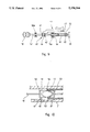
- FIG. 7 is a schematic side view of the drive of the present invention.
- FIG. 8 is a plan view of the drive means of the apparatus of FIG. 1;
- FIG. 9 is a schematic view of a coupling of a linear drive to a medium-speed rotary drive.
- FIG. 10 is a schematic cross-sectional view of an embodiment for a motor reciprocating linear drive of a connecting part.
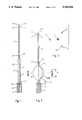
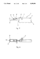
- the inventive apparatus has a flexible hollow wire 1, which is e.g. formed by helically winding three strands 2,3,4.
- the hollow wire 4 is guided by a catheter 6.
- a joining area 7 the helical winding of the individual wires 2,3,4 is removed and they are axially guided substantially parallel to one another until they are again brought together in a further joining area 8, which is spaced from the first area and a further portion 9 of the hollow wire 1 is formed.
- On the joining points 7,8 can be mounted sleeves 11,12, which prevent an untwisting of the wound areas.
- a sleeve 14 can also be fixed to the hollow wire 1 at the proximal end 13.
- a taut wire 21 extends through the entire hollow wire 1 freely and axially thereto.
- the end of the taut wire 21 projecting out of the proximal end 13 of the hollow wire attachment 9 is provided with an abutment in the form of a ball or sphere 22, whose diameter is at least over the internal diameter of the attachment 9 and preferably corresponds to or is greater than the external diameter of said hollow wire attachment 9 or the sleeve 14.
- the ball 22 or a corresponding, optionally conically shaped abutment can be provided with cutting edges, which are either formed directly on the ball, by diamond chips or the like applied, or by a foil provided with micro-cutting edges. Particularly in the latter case the abutment is preferably constructed as a cone or cylinder.
- the individual wires 2,3,4 extending freely between the areas 7,8 are at least in the central part of their longitudinal extension A provided with cutting edges 16.
- the cutting edges 16 are substantially tangential to the central taut wire 21 or a spheroid formed by the wires 2,3,4. They can be formed by one side of each wire and if only one rotation direction is provided it is in the latter. However, they are preferably formed on two sides, so that the inventive apparatus can be used with two rotation directions.
- the cutting edges 16 are as far as possible towards the outside, as shown in FIG. 3.
- the wires 2,3,4 of the basket or cage formed by them must have no cutting edges and can instead be blunt, e.g. formed from round wire, as shown in FIG. 3a.
- wires 2 to 4 with their cutting edge areas 16 in the unloaded position shown in FIG. 1, in which they only surround a small cross-sectional surface are introduced through the catheter 6 into the vicinity of a stenosis of a vessel, optionally following recanalization, then an atherectomy can be carried out, in that the taut wire 21 is drawn in the distal direction from the distal end of the apparatus.
- the wires 2 to 4 are axially loaded and their ends are axially pressed against one another, so that the central areas of the wires are pressed towards the outside.
- an optionally completely closed stenosis can take place in per se known manner.
- the means according to the invention can be advanced in front of the stenosis and the taut wire 21 can then serve as a guidance wire.
- the taut wire 21 is then rotated, so that the ball 22 or the like can recanalize the stenosis and can therefore create a passage through the same.
- the entire means, including the freely extending wire areas 2 to 4 can be passed through the stenosis and by drawing rearwards the wires 2 to 4 the aforementioned widening effect can be obtained.
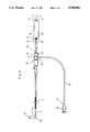
- the scaled off plaque material is preferably suctioned off through the catheter 6 and, as shown in FIGS. 1 and 2, this can take place alongside the hollow wire 1. It is also possible to use a catheter with two orifices and it is possible to inject through the secondary orifice streptokinase or the like for the partial dissolving of deposits.
- the catheter 6 has in its distal area 27 a branch 29, to which is fixed a hose portion 30. Its end 37 remote from the branch 29 can be connected by an adaptor 28 to a suction means, in order to suctioned off through the catheter 6 the broken off deposits.
- the suction means is a motor, particularly electric and, preferably, battery-operated pump, whose suction rate can be varied, controlled or regulated.
- a tight passage for the wires 1, 21 is provided on the proximal side of the branch 29.
- the seal is preferably constructed in such a way that in a valve part 61, such as a hemostatic valve, is provided a short, elastic, flexible hose part, whose diameter in the unloaded state is such that the hollow wire 1 and also the taut wire 21 with its ball 22 can be freely passed through the hose part.
- a sleeve attachment 62 is provided with a thread and on it is placed an internally threaded cap 63. When the cap 63 is threaded on in a direction towards the branch 29 it axially compresses the hose part by a face 64 thereof. Therefore, the hose part engages on the hollow wire 1 and forms a reliable seal.
- the hollow wire 1 can be axially moved backwards and forwards under friction.
- a distal end 31 of the hollow wire 1 is axially displaceable in a driven hollow shaft 39 of a drive motor 38, but can be braced to the shaft in non-rotary axial manner, e.g. by a bracing mechanism 32.
- the hollow shaft 39 is mounted so as to rotate in the motor part 38.
- Either shaft 39 or another hollow shaft 33 projects out of the rear end 35 of the motor 38.
- Through the hollow shafts 39, 33 extends the taut wire 21, which is connected in non-rotary manner to the shaft 33 by a clamping mechanism 36, whereby the shaft can be constructed in one piece with the shaft 39.
- the motor 38 is switched on, so that the taut wire 21 and optionally also the hollow wire 1 and, in particular, the optionally roughened ball 22 connected to the taut wire 21 is rotated.
- the ball 22 is moved in the proximal direction with its cutting action brought about by the rotation and is forced through the closure until a recanalization has been brought about.
- the hollow wire 1 with its front hollow wire attachment 9 and the individual wire portions 2 to 4 can be moved through the canal to the proximal side of the stenosis.
- the clamping mechanism 38 can then be released.
- the taut wire 21 is then drawn back, so that there is a relative displacement of wire 21 with respect to the hollow wire 1.
- the taut wire 21 takes the hollow wire attachment 9 with it, so that the individual wires 2, 3 and 4 provided with cutting edges 16 are forced radially outwards.
- the clamping mechanism 36 is refixed and subsequently the motor 38 is operated, so that the basket, formed by the wires 2 to 4 is rotated and, accompanied by the drawing back of the motor 38 and therefore the two wires 1 and 21, a desired hollow cylinder is cut out of the stenosis.
- This process can optionally be repeated several times until the desired diameter in the vessel is obtained.
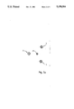
- FIG. 5 on the proximal end of the hollow wire 1 is placed a forceps-like device, which is controllable by a wire or the like located in the interior of the hollow wire 1 for the purpose of opening and closing the forceps.
- the forceps have two forcep jaws 19 with cutting edges 16.
- the outer edges of the jaws 19 are ground and form the outer cutting edges 17.
- the front edges of the jaws 19 are ground for forming the front cutting edges 18.
- This apparatus is preferably used in such a manner that, in the closed state, the forceps are advanced through the insertion catheter 6 up to the stenosis.
- the forceps are rotated by the hollow wire 1 and in the case of a further advance by the latter, the front cutting edges 18 can penetrate the stenosis.
- the forcep is then expanded to the desired diameter in known manner, e.g. controlled by the taut wire 21 and then drawn back, accompanied by rotation.
- the stenosis is then shelled out to the set diameter by the outer cutting edges 17.
- FIG. 6 shows another embodiment, which is based on a type of Silverman needle 60, which has two ends 61 with cutting edges 16.
- the two ends 61 have an internal tension, so that they spread or expand to the extent made possible by the displaceable sleeve 62.
- the sleeve 62 can be connected to or be integral with the hollow wire 1 and the needle 60 can be rotated by the inner wire otherwise used as the taut wire 21 if it is connected in non-rotary manner to the needle 60.
- the ends 61 expand as a result of their inherent tension to the desired diameter and, in accordance with FIG. 5, by means of the cutting edges 16 it is possible to hollow out a stenosis by rotating the needle 60 and drawing forwards and backwards the needle 60 and the sleeve 62.
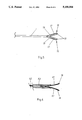
- the inventive drive 1' has a casing 2', which houses an electric motor and a power supply, such as a battery or an accumulator and which can be inserted in the casing through opening 4'.
- the casing also contains a speed regulator for the motor, which is controllable by a setting knob 6', so that the speed can be set and adjusted in desired ranges, e.g. between 0 and 2,000 r.p.m. or higher.
- the casing also contains a display 7', in this case a LCD, which shows the amount of power of the power supply means which has been consumed and therefore when a replacemnent is necessary.
- the drive 1' is also provided with an on/off switch for switching the rotary drive on and off.
- a holding bridge 9' is provided on the casing 2' and at its end 11' remote from the latter, has an opening 12' which is open from the top with undercut, lateral grooves 13' and into which are insertable the radial flanges on a hollow guide part, such as a suction catheter, so that the latter can be fixed relative to the drive 1' and, in particular, its casing 2', more especially in the axial direction.
- a connecting part 10' with a driving shaft 14' which is provided at its free end with a connecting attachment 16', such as e.g. a male Luer-Lok.
- a connecting attachment 16' such as e.g. a male Luer-Lok.
- the female Luer-Lok part can be connected in non-rotary manner a device for removing deposits by the rotation thereof, such as a rotational spiral.
- the device has over its length roughly corresponding to that of the hollow guide part or catheter a straight shaft and can be provided at its proximal end, i.e. the end remote from the drive 1', with a helical construction, as well as following onto the latter a ball with or without a cutting edge means, or with a radially spreadable basket-like member, optionally with a cutting edge means.
- a slide part 17' On the top of the casing is provided a slide part 17', to which is connected the shaft 14' so as to be rotatable, but axially fixed with respect thereto.
- the shaft 14' is once again in axial, but non-rotary engagement with a driven stub of the motor located in the casing 2'.
- the driving shaft 14' carries at its front end in non-rotary manner the Luer-Lok 16'. It also has non-rotary radial flanges 41, 42 which are spaced from one another and which can e.g. be constructed on an engaged sleeve 43, such as a brass sleeve soldered to the shaft 14'.
- a C-shaped part 44 engages between the flanges 41, 42 on the shaft 14' or the sleeve 43 connected thereto, whilst ensuring rotation. This part 44 is snapped over the shaft 14' or the sleeve 43 and is firmly connected to the slide part and is e.g. constructed in one piece therewith.
- the shaft 14' projects into a guide sleeve 45, which is mounted in rotary manner relative to the casing by a bearing 46.
- the driven shaft 47 of a motor 48 projects into the sleeve 45 and is connected in non-rotary manner thereto by a pin 50 passing through transverse bores 49.
- the cross-section of the part 14a of shaft 14' projecting into the guide sleeve 45, as well as the internal cross-section of sleeve 45 are not circular, but instead have a shape differing from the circular, e.g. flattened, so that the shaft 14' can also be rotated by the guide sleeve 45 driven by the motor 48.
- the shaft 14' is also guided by a bearing 50a with respect to which it is displaceable and rotatable.
- FIG. 10 diagrammatically shows an embodiment for transforming the linear reciprocating movement derived from the rotary drive for the connecting part.
- the connecting part is rotatable, but is axially fixed to a sleeve 51, similar to sleeve 43, e.g. by radial flanges 52 firmly engaging on the connecting part on either side of the sleeve 51.
- a conventional bearing means In order to reduce friction, it is possible to provide within the sleeve 51 between the latter and the connecting part 14a conventional bearing means.
- a closed groove In the outer circumference of the sleeve is provided a closed groove, which passes in meander-like manner from one face of the sleeve and then around the same and back to the first face.
- the cam 56 of a further sleeve 57 engages in the groove. So that the sleeve 51 does not rotate with the sleeve 57, it is guided by a cam 61 in a groove 62 of the wall 63 of the casing 2 or a part firmly connected thereto. During the rotation of the sleeve 57 the cam 56 is urged against the wall of the groove 53 of the sleeve 51 inclined with respect to its rotation direction. As the sleeve cannot rotate with it due to its linear guide 61, 62, it is axially displaced by the cam 56 until the latter arrives at one of the reversal points of the groove 53 at the faces of sleeve 51, where the linear movement is then reversed.
- the rotary drive of the rotary sleeve 57 can be derived from the rotary drive of the motor and, as the reciprocating movement of the sleeve 51 and, therefore, the rotary movement of the sleeve 57 is much smaller than the rotary movement of the motor, by a reduction gear, which can e.g. be constructed in the form of a sun gear-planet gear with an annular gear constructed in the sleeve 57, in the form of a clockwork motions or the like.
- the rotary drive of the shaft 14' and therefore the connecting part 10' takes place in the same way to that which has been described relative to FIG. 9.
Abstract
Description
Claims (1)
Priority Applications (5)
| Application Number | Priority Date | Filing Date | Title |
|---|---|---|---|
| ES90125332T ES2085880T3 (en) | 1990-02-14 | 1990-12-22 | DEVICE FOR ATTERECTOMY. |
| EP90125332A EP0442137B1 (en) | 1990-02-14 | 1990-12-22 | Atherectomy device |
| AT90125332T ATE134123T1 (en) | 1990-02-14 | 1990-12-22 | DEVICE FOR ATHERECTOMY |
| DE59010138T DE59010138D1 (en) | 1990-02-14 | 1990-12-22 | Atherectomy device |
| JP1991005635U JP2549084Y2 (en) | 1990-02-14 | 1991-02-13 | Atherectomy device |
Applications Claiming Priority (4)
| Application Number | Priority Date | Filing Date | Title |
|---|---|---|---|
| DE19904004507 DE4004507A1 (en) | 1990-02-14 | 1990-02-14 | Atheroma clearing instrument with rotary element |
| DE4004507 | 1990-02-14 | ||
| DE9004074[U] | 1990-04-07 | ||
| DE9004074U DE9004074U1 (en) | 1990-04-07 | 1990-04-07 |
Publications (1)
| Publication Number | Publication Date |
|---|---|
| US5158564A true US5158564A (en) | 1992-10-27 |
Family
ID=25890103
Family Applications (1)
| Application Number | Title | Priority Date | Filing Date |
|---|---|---|---|
| US07/551,013 Expired - Fee Related US5158564A (en) | 1990-02-14 | 1990-07-11 | Atherectomy apparatus |
Country Status (1)
| Country | Link |
|---|---|
| US (1) | US5158564A (en) |
Cited By (210)
| Publication number | Priority date | Publication date | Assignee | Title |
|---|---|---|---|---|
| WO1993019679A1 (en) * | 1992-04-07 | 1993-10-14 | The Johns Hopkins University | A percutaneous mechanical fragmentation catheter system |
| US5336234A (en) * | 1992-04-17 | 1994-08-09 | Interventional Technologies, Inc. | Method and apparatus for dilatation of a stenotic vessel |
| US5417703A (en) * | 1993-07-13 | 1995-05-23 | Scimed Life Systems, Inc. | Thrombectomy devices and methods of using same |
| US5441510A (en) * | 1993-09-01 | 1995-08-15 | Technology Development Center | Bi-axial cutter apparatus for catheter |
| US5449369A (en) * | 1992-12-01 | 1995-09-12 | Intelliwire, Inc. | Flexible elongate device having a vibratory impact tip and method of its use |
| US5499632A (en) * | 1994-05-04 | 1996-03-19 | Devices For Vascular Intervention | Guide wire migration controller |
| JPH08503154A (en) * | 1992-11-13 | 1996-04-09 | シメッド ライフ システムズ インコーポレイテッド | Device and method for endovascular occlusion removal |
| WO1997000048A1 (en) * | 1995-06-16 | 1997-01-03 | Vitas Corporation Usa | Apparatus and method for dilation of hollow organs |
| US5713913A (en) * | 1996-11-12 | 1998-02-03 | Interventional Technologies Inc. | Device and method for transecting a coronary artery |
| US5722945A (en) * | 1990-07-17 | 1998-03-03 | Aziz Yehia Anis | Removal of tissue |
| US5733296A (en) * | 1996-02-06 | 1998-03-31 | Devices For Vascular Intervention | Composite atherectomy cutter |
| US5816923A (en) * | 1993-12-09 | 1998-10-06 | Devices For Vascular Intervention, Inc. | Flexible composite drive shaft for transmitting torque |
| US5827292A (en) * | 1990-07-17 | 1998-10-27 | Anis; Aziz Yehia | Removal of tissue |
| US5868708A (en) * | 1997-05-07 | 1999-02-09 | Applied Medical Resources Corporation | Balloon catheter apparatus and method |
| US5882329A (en) * | 1997-02-12 | 1999-03-16 | Prolifix Medical, Inc. | Apparatus and method for removing stenotic material from stents |
| US5897566A (en) * | 1996-07-15 | 1999-04-27 | Shturman Cardiology Systems, Inc. | Rotational atherectomy device |
| US5919161A (en) * | 1994-05-04 | 1999-07-06 | Devices For Vascular Intervention | Guidewire migration controller |
| WO1999035977A1 (en) * | 1998-01-16 | 1999-07-22 | Lumend, Inc. | Catheter apparatus for treating arterial occlusions |
| US6007513A (en) * | 1990-07-17 | 1999-12-28 | Aziz Yehia Anis | Removal of tissue |
| US6022363A (en) * | 1998-12-16 | 2000-02-08 | Micro Therapeutics, Inc. | Rotatable dynamic seal and guide for a medical obstruction treatment device sub-assembly coupled to a drive motor unit |
| US6066152A (en) * | 1998-12-16 | 2000-05-23 | Micro Therapeutics, Inc. | Rotatable attachment mechanism for attaching a medical obstruction treatment device sub-assembly to a drive motor unit |
| US6081738A (en) * | 1998-01-15 | 2000-06-27 | Lumend, Inc. | Method and apparatus for the guided bypass of coronary occlusions |
| US6090118A (en) * | 1998-07-23 | 2000-07-18 | Mcguckin, Jr.; James F. | Rotational thrombectomy apparatus and method with standing wave |
| US6096054A (en) * | 1998-03-05 | 2000-08-01 | Scimed Life Systems, Inc. | Expandable atherectomy burr and method of ablating an occlusion from a patient's blood vessel |
| US6126635A (en) * | 1993-09-29 | 2000-10-03 | Advanced Cardiovascular Systems, Inc. | Adjustable treatment chamber catheter |
| US6132444A (en) * | 1997-08-14 | 2000-10-17 | Shturman Cardiology Systems, Inc. | Eccentric drive shaft for atherectomy device and method for manufacture |
| US6139557A (en) * | 1997-11-07 | 2000-10-31 | Prolifix Medical, Inc. | Apparatus for making wire with radial expansible guide section and methods of manufacturing the same |
| US6203518B1 (en) | 1990-07-17 | 2001-03-20 | Aziz Yehia Anis | Removal of tissue |
| US6217595B1 (en) | 1996-11-18 | 2001-04-17 | Shturman Cardiology Systems, Inc. | Rotational atherectomy device |
| US6267679B1 (en) | 1997-12-31 | 2001-07-31 | Jack W. Romano | Method and apparatus for transferring drilling energy to a cutting member |
| US6319242B1 (en) | 1997-02-12 | 2001-11-20 | Prolifix Medical, Inc. | Apparatus and method for controlled removal of stenotic material from stents |
| WO2001095810A2 (en) | 2000-06-14 | 2001-12-20 | Harmonia Medical Technologies, Inc. | Surgical instrument and method of using the same |
| US6371928B1 (en) | 1997-11-07 | 2002-04-16 | Prolifix Medical, Inc. | Guidewire for positioning a catheter against a lumen wall |
| US6406442B1 (en) | 1996-11-07 | 2002-06-18 | Prolifix Medical, Inc. | Guidewire for precision catheter positioning |
| US6494890B1 (en) | 1997-08-14 | 2002-12-17 | Shturman Cardiology Systems, Inc. | Eccentric rotational atherectomy device |
| US20030028206A1 (en) * | 1999-02-02 | 2003-02-06 | Samuel Shiber | Vessel cleaner and barrier |
| US20030040762A1 (en) * | 2001-08-22 | 2003-02-27 | Gerald Dorros | Apparatus and methods for treating stroke and controlling cerebral flow characteristics |
| US6565588B1 (en) | 2000-04-05 | 2003-05-20 | Pathway Medical Technologies, Inc. | Intralumenal material removal using an expandable cutting device |
| US20030144683A1 (en) * | 2001-12-13 | 2003-07-31 | Avantec Vascular Corporation | Inflatable members having concentrated force regions |
| US20030153870A1 (en) * | 2002-02-14 | 2003-08-14 | Intella Interventional Systems, Inc. | Balloon catheter for creating a longitudinal channel in a lesion and method |
| US20040006306A1 (en) * | 2002-05-14 | 2004-01-08 | Bacchus Vascular Inc. | Apparatus and method for removing occlusive material within blood vessels |
| US6758851B2 (en) | 1999-02-02 | 2004-07-06 | Samuel Shiber | Vessel cleaner |
| US20040176663A1 (en) * | 2002-12-16 | 2004-09-09 | Edrich Vascular Devices, Inc. | Endovascular stapler |
| US6818001B2 (en) | 2000-04-05 | 2004-11-16 | Pathway Medical Technologies, Inc. | Intralumenal material removal systems and methods |
| US20050004582A1 (en) * | 2002-12-16 | 2005-01-06 | Edoga John K. | Endovascular stapler |
| US20050033225A1 (en) * | 2003-08-08 | 2005-02-10 | Scimed Life Systems, Inc. | Catheter shaft for regulation of inflation and deflation |
| US20050124973A1 (en) * | 2001-08-22 | 2005-06-09 | Gerald Dorros | Apparatus and methods for treating stroke and controlling cerebral flow characteristics |
| US20050154400A1 (en) * | 2003-12-18 | 2005-07-14 | Asahi Intecc Co., Ltd | Medical treating tool |
| US6936025B1 (en) | 1992-05-19 | 2005-08-30 | Bacchus Vascular, Inc. | Thrombolysis device |
| US20050277979A1 (en) * | 2001-08-22 | 2005-12-15 | Gerald Dorros | Apparatus and methods for treating stroke and controlling cerebral flow characteristics |
| US20060000869A1 (en) * | 2004-05-17 | 2006-01-05 | Datascope Investment Corp. | Surgical stapling system |
| US7037316B2 (en) | 1997-07-24 | 2006-05-02 | Mcguckin Jr James F | Rotational thrombectomy device |
| US7291146B2 (en) | 2003-09-12 | 2007-11-06 | Minnow Medical, Inc. | Selectable eccentric remodeling and/or ablation of atherosclerotic material |
| US7291158B2 (en) | 2004-11-12 | 2007-11-06 | Boston Scientific Scimed, Inc. | Cutting balloon catheter having a segmented blade |
| US20090125044A1 (en) * | 2007-11-14 | 2009-05-14 | Lary Todd P | Treatment of Coronary Stenosis |
| US7566319B2 (en) | 2004-04-21 | 2009-07-28 | Boston Scientific Scimed, Inc. | Traction balloon |
| US20090292307A1 (en) * | 2008-05-22 | 2009-11-26 | Nasser Razack | Mechanical embolectomy device and method |
| US20090299392A1 (en) * | 2008-05-30 | 2009-12-03 | Cardiovascular Systems, Inc. | Eccentric abrading element for high-speed rotational atherectomy devices |
| US20090299391A1 (en) * | 2008-05-30 | 2009-12-03 | Cardiovascular Systems, Inc. | Eccentric abrading and cutting head for high-speed rotational atherectomy devices |
| US20090306689A1 (en) * | 2008-06-05 | 2009-12-10 | Cardiovascular Systems, Inc. | Bidirectional expandable head for rotational atherectomy device |
| US20090306690A1 (en) * | 2008-06-05 | 2009-12-10 | Cardiovascular Systems, Inc. | Abrasive nose cone with expandable cutting and sanding region for rotational atherectomy device |
| US7632288B2 (en) | 2003-05-12 | 2009-12-15 | Boston Scientific Scimed, Inc. | Cutting balloon catheter with improved pushability |
| US7645261B2 (en) | 1999-10-22 | 2010-01-12 | Rex Medical, L.P | Double balloon thrombectomy catheter |
| US20100087850A1 (en) * | 2008-10-03 | 2010-04-08 | Nasser Razack | Mechanical Embolectomy Device and Method |
| US20100137899A1 (en) * | 2008-12-02 | 2010-06-03 | Nasser Razack | Mechanical Embolectomy Device and Method |
| US7742795B2 (en) | 2005-03-28 | 2010-06-22 | Minnow Medical, Inc. | Tuned RF energy for selective treatment of atheroma and other target tissues and/or structures |
| US7754047B2 (en) | 2004-04-08 | 2010-07-13 | Boston Scientific Scimed, Inc. | Cutting balloon catheter and method for blade mounting |
| US7758604B2 (en) | 2003-05-29 | 2010-07-20 | Boston Scientific Scimed, Inc. | Cutting balloon catheter with improved balloon configuration |
| US7887557B2 (en) | 2003-08-14 | 2011-02-15 | Boston Scientific Scimed, Inc. | Catheter having a cutting balloon including multiple cavities or multiple channels |
| US7993358B2 (en) | 2005-02-11 | 2011-08-09 | Boston Scientific Scimed, Inc. | Cutting balloon catheter having increased flexibility regions |
| DE102010009723A1 (en) * | 2010-03-01 | 2011-09-01 | Andramed Gmbh | Guidewire / catheter guided valvulotome |
| US20110213391A1 (en) * | 2010-02-26 | 2011-09-01 | Cardiovascular Systems, Inc. | Rotational atherectomy device with electric motor |
| US8038691B2 (en) | 2004-11-12 | 2011-10-18 | Boston Scientific Scimed, Inc. | Cutting balloon catheter having flexible atherotomes |
| US20120059309A1 (en) * | 2010-09-07 | 2012-03-08 | Angiodynamics, Inc. | Fluid Delivery and Treatment Device and Method of Use |
| US8162964B2 (en) | 2008-06-05 | 2012-04-24 | Cardiovascular Systems, Inc. | Split flexible tube biasing and directional atherectomy device and method |
| AU2009202365B2 (en) * | 2001-08-22 | 2012-05-03 | W. L. Gore & Associates, Inc. | Apparatus and methods for treating stroke and controlling cerebral flow characteristics |
| US20120239008A1 (en) * | 2010-10-19 | 2012-09-20 | Distal Access, Llc | Apparatus for rotating medical devices, systems including the apparatus, and associated methods |
| US8396548B2 (en) | 2008-11-14 | 2013-03-12 | Vessix Vascular, Inc. | Selective drug delivery in a lumen |
| US8401667B2 (en) | 2008-11-17 | 2013-03-19 | Vessix Vascular, Inc. | Selective accumulation of energy with or without knowledge of tissue topography |
| US8414543B2 (en) | 1999-10-22 | 2013-04-09 | Rex Medical, L.P. | Rotational thrombectomy wire with blocking device |
| US8491614B2 (en) | 2010-06-22 | 2013-07-23 | Lemaitre Vascular, Inc. | Over-the-wire valvulotomes |
| US8496653B2 (en) | 2007-04-23 | 2013-07-30 | Boston Scientific Scimed, Inc. | Thrombus removal |
| US8551096B2 (en) | 2009-05-13 | 2013-10-08 | Boston Scientific Scimed, Inc. | Directional delivery of energy and bioactives |
| US8597313B2 (en) | 2007-06-11 | 2013-12-03 | Cardiovascular Systems, Inc. | Eccentric abrading head for high-speed rotational atherectomy devices |
| AU2012209037B2 (en) * | 2001-08-22 | 2013-12-12 | W. L. Gore & Associates, Inc. | Apparatus and methods for treating stroke and controlling cerebral flow characteristics |
| US8685049B2 (en) | 2010-11-18 | 2014-04-01 | Rex Medical L.P. | Cutting wire assembly for use with a catheter |
| US8685050B2 (en) | 2010-10-06 | 2014-04-01 | Rex Medical L.P. | Cutting wire assembly for use with a catheter |
| US8702736B2 (en) | 2010-11-22 | 2014-04-22 | Rex Medical L.P. | Cutting wire assembly for use with a catheter |
| US8880185B2 (en) | 2010-06-11 | 2014-11-04 | Boston Scientific Scimed, Inc. | Renal denervation and stimulation employing wireless vascular energy transfer arrangement |
| US8920414B2 (en) | 2004-09-10 | 2014-12-30 | Vessix Vascular, Inc. | Tuned RF energy and electrical tissue characterization for selective treatment of target tissues |
| US8951251B2 (en) | 2011-11-08 | 2015-02-10 | Boston Scientific Scimed, Inc. | Ostial renal nerve ablation |
| US8974451B2 (en) | 2010-10-25 | 2015-03-10 | Boston Scientific Scimed, Inc. | Renal nerve ablation using conductive fluid jet and RF energy |
| US9023034B2 (en) | 2010-11-22 | 2015-05-05 | Boston Scientific Scimed, Inc. | Renal ablation electrode with force-activatable conduction apparatus |
| US9028472B2 (en) | 2011-12-23 | 2015-05-12 | Vessix Vascular, Inc. | Methods and apparatuses for remodeling tissue of or adjacent to a body passage |
| US9028485B2 (en) | 2010-11-15 | 2015-05-12 | Boston Scientific Scimed, Inc. | Self-expanding cooling electrode for renal nerve ablation |
| US9050106B2 (en) | 2011-12-29 | 2015-06-09 | Boston Scientific Scimed, Inc. | Off-wall electrode device and methods for nerve modulation |
| US9055966B2 (en) | 2008-05-30 | 2015-06-16 | Cardiovascular Systems, Inc. | Eccentric abrading and cutting head for high-speed rotational atherectomy devices |
| US9060761B2 (en) | 2010-11-18 | 2015-06-23 | Boston Scientific Scime, Inc. | Catheter-focused magnetic field induced renal nerve ablation |
| US9079000B2 (en) | 2011-10-18 | 2015-07-14 | Boston Scientific Scimed, Inc. | Integrated crossing balloon catheter |
| US9084609B2 (en) | 2010-07-30 | 2015-07-21 | Boston Scientific Scime, Inc. | Spiral balloon catheter for renal nerve ablation |
| US9089350B2 (en) | 2010-11-16 | 2015-07-28 | Boston Scientific Scimed, Inc. | Renal denervation catheter with RF electrode and integral contrast dye injection arrangement |
| US9119632B2 (en) | 2011-11-21 | 2015-09-01 | Boston Scientific Scimed, Inc. | Deflectable renal nerve ablation catheter |
| US9119600B2 (en) | 2011-11-15 | 2015-09-01 | Boston Scientific Scimed, Inc. | Device and methods for renal nerve modulation monitoring |
| US9125667B2 (en) | 2004-09-10 | 2015-09-08 | Vessix Vascular, Inc. | System for inducing desirable temperature effects on body tissue |
| US9155589B2 (en) | 2010-07-30 | 2015-10-13 | Boston Scientific Scimed, Inc. | Sequential activation RF electrode set for renal nerve ablation |
| US9162046B2 (en) | 2011-10-18 | 2015-10-20 | Boston Scientific Scimed, Inc. | Deflectable medical devices |
| US9173696B2 (en) | 2012-09-17 | 2015-11-03 | Boston Scientific Scimed, Inc. | Self-positioning electrode system and method for renal nerve modulation |
| US9186210B2 (en) | 2011-10-10 | 2015-11-17 | Boston Scientific Scimed, Inc. | Medical devices including ablation electrodes |
| US9186209B2 (en) | 2011-07-22 | 2015-11-17 | Boston Scientific Scimed, Inc. | Nerve modulation system having helical guide |
| US9192435B2 (en) | 2010-11-22 | 2015-11-24 | Boston Scientific Scimed, Inc. | Renal denervation catheter with cooled RF electrode |
| US9192790B2 (en) | 2010-04-14 | 2015-11-24 | Boston Scientific Scimed, Inc. | Focused ultrasonic renal denervation |
| US9220561B2 (en) | 2011-01-19 | 2015-12-29 | Boston Scientific Scimed, Inc. | Guide-compatible large-electrode catheter for renal nerve ablation with reduced arterial injury |
| US9220558B2 (en) | 2010-10-27 | 2015-12-29 | Boston Scientific Scimed, Inc. | RF renal denervation catheter with multiple independent electrodes |
| US9265969B2 (en) | 2011-12-21 | 2016-02-23 | Cardiac Pacemakers, Inc. | Methods for modulating cell function |
| US9277955B2 (en) | 2010-04-09 | 2016-03-08 | Vessix Vascular, Inc. | Power generating and control apparatus for the treatment of tissue |
| US9282991B2 (en) | 2010-10-06 | 2016-03-15 | Rex Medical, L.P. | Cutting wire assembly with coating for use with a catheter |
| US9289255B2 (en) | 2002-04-08 | 2016-03-22 | Medtronic Ardian Luxembourg S.A.R.L. | Methods and apparatus for renal neuromodulation |
| US9297845B2 (en) | 2013-03-15 | 2016-03-29 | Boston Scientific Scimed, Inc. | Medical devices and methods for treatment of hypertension that utilize impedance compensation |
| US9326751B2 (en) | 2010-11-17 | 2016-05-03 | Boston Scientific Scimed, Inc. | Catheter guidance of external energy for renal denervation |
| US9358365B2 (en) | 2010-07-30 | 2016-06-07 | Boston Scientific Scimed, Inc. | Precision electrode movement control for renal nerve ablation |
| US9364284B2 (en) | 2011-10-12 | 2016-06-14 | Boston Scientific Scimed, Inc. | Method of making an off-wall spacer cage |
| US9408661B2 (en) | 2010-07-30 | 2016-08-09 | Patrick A. Haverkost | RF electrodes on multiple flexible wires for renal nerve ablation |
| US9420955B2 (en) | 2011-10-11 | 2016-08-23 | Boston Scientific Scimed, Inc. | Intravascular temperature monitoring system and method |
| US9433760B2 (en) | 2011-12-28 | 2016-09-06 | Boston Scientific Scimed, Inc. | Device and methods for nerve modulation using a novel ablation catheter with polymeric ablative elements |
| USD766433S1 (en) | 2013-11-04 | 2016-09-13 | Cardiovascular Systems, Inc. | Eccentric crown |
| US9452017B2 (en) | 2012-05-11 | 2016-09-27 | Medtronic Ardian Luxembourg S.A.R.L. | Multi-electrode catheter assemblies for renal neuromodulation and associated systems and methods |
| US9463062B2 (en) | 2010-07-30 | 2016-10-11 | Boston Scientific Scimed, Inc. | Cooled conductive balloon RF catheter for renal nerve ablation |
| US9468457B2 (en) | 2013-09-30 | 2016-10-18 | Cardiovascular Systems, Inc. | Atherectomy device with eccentric crown |
| US9539416B2 (en) | 2009-02-10 | 2017-01-10 | Vesatek, Llc | System and method for traversing an arterial occlusion |
| US9550010B2 (en) | 2010-07-02 | 2017-01-24 | Agnovos Healthcare, Llc | Methods of treating degenerative bone conditions |
| US9554848B2 (en) | 1999-04-05 | 2017-01-31 | Medtronic, Inc. | Ablation catheters and associated systems and methods |
| US9579149B2 (en) | 2014-03-13 | 2017-02-28 | Medtronic Ardian Luxembourg S.A.R.L. | Low profile catheter assemblies and associated systems and methods |
| US9579030B2 (en) | 2011-07-20 | 2017-02-28 | Boston Scientific Scimed, Inc. | Percutaneous devices and methods to visualize, target and ablate nerves |
| US9636173B2 (en) | 2010-10-21 | 2017-05-02 | Medtronic Ardian Luxembourg S.A.R.L. | Methods for renal neuromodulation |
| US9649156B2 (en) | 2010-12-15 | 2017-05-16 | Boston Scientific Scimed, Inc. | Bipolar off-wall electrode device for renal nerve ablation |
| US9668811B2 (en) | 2010-11-16 | 2017-06-06 | Boston Scientific Scimed, Inc. | Minimally invasive access for renal nerve ablation |
| US9687166B2 (en) | 2013-10-14 | 2017-06-27 | Boston Scientific Scimed, Inc. | High resolution cardiac mapping electrode array catheter |
| US9693821B2 (en) | 2013-03-11 | 2017-07-04 | Boston Scientific Scimed, Inc. | Medical devices for modulating nerves |
| US9707036B2 (en) | 2013-06-25 | 2017-07-18 | Boston Scientific Scimed, Inc. | Devices and methods for nerve modulation using localized indifferent electrodes |
| US9707035B2 (en) | 2002-04-08 | 2017-07-18 | Medtronic Ardian Luxembourg S.A.R.L. | Methods for catheter-based renal neuromodulation |
| US9713730B2 (en) | 2004-09-10 | 2017-07-25 | Boston Scientific Scimed, Inc. | Apparatus and method for treatment of in-stent restenosis |
| US9750525B2 (en) | 2013-03-14 | 2017-09-05 | Cardiovascular Systems, Inc. | Devices, systems and methods for an oscillating crown drive for rotational atherectomy |
| US9770606B2 (en) | 2013-10-15 | 2017-09-26 | Boston Scientific Scimed, Inc. | Ultrasound ablation catheter with cooling infusion and centering basket |
| US9808300B2 (en) | 2006-05-02 | 2017-11-07 | Boston Scientific Scimed, Inc. | Control of arterial smooth muscle tone |
| US9808311B2 (en) | 2013-03-13 | 2017-11-07 | Boston Scientific Scimed, Inc. | Deflectable medical devices |
| US9827039B2 (en) | 2013-03-15 | 2017-11-28 | Boston Scientific Scimed, Inc. | Methods and apparatuses for remodeling tissue of or adjacent to a body passage |
| US9833283B2 (en) | 2013-07-01 | 2017-12-05 | Boston Scientific Scimed, Inc. | Medical devices for renal nerve ablation |
| US9888961B2 (en) | 2013-03-15 | 2018-02-13 | Medtronic Ardian Luxembourg S.A.R.L. | Helical push wire electrode |
| US9895194B2 (en) | 2013-09-04 | 2018-02-20 | Boston Scientific Scimed, Inc. | Radio frequency (RF) balloon catheter having flushing and cooling capability |
| CN107735038A (en) * | 2015-06-25 | 2018-02-23 | 柯惠有限合伙公司 | Tissue with adjustable cross sectional dimensions removes conduit |
| US9907609B2 (en) | 2014-02-04 | 2018-03-06 | Boston Scientific Scimed, Inc. | Alternative placement of thermal sensors on bipolar electrode |
| US9925001B2 (en) | 2013-07-19 | 2018-03-27 | Boston Scientific Scimed, Inc. | Spiral bipolar electrode renal denervation balloon |
| US9936970B2 (en) | 2013-03-14 | 2018-04-10 | Cardiovascular Systems, Inc. | Devices, systems and methods for an oscillating crown drive for rotational atherectomy |
| US9943365B2 (en) | 2013-06-21 | 2018-04-17 | Boston Scientific Scimed, Inc. | Renal denervation balloon catheter with ride along electrode support |
| US9956033B2 (en) | 2013-03-11 | 2018-05-01 | Boston Scientific Scimed, Inc. | Medical devices for modulating nerves |
| US9962223B2 (en) | 2013-10-15 | 2018-05-08 | Boston Scientific Scimed, Inc. | Medical device balloon |
| US9974607B2 (en) | 2006-10-18 | 2018-05-22 | Vessix Vascular, Inc. | Inducing desirable temperature effects on body tissue |
| US10022182B2 (en) | 2013-06-21 | 2018-07-17 | Boston Scientific Scimed, Inc. | Medical devices for renal nerve ablation having rotatable shafts |
| US10052122B2 (en) | 2014-01-17 | 2018-08-21 | Cardiovascular Systems, Inc. | Spin-to-open atherectomy device with electric motor control |
| US10076382B2 (en) | 2010-10-25 | 2018-09-18 | Medtronic Ardian Luxembourg S.A.R.L. | Catheter apparatuses having multi-electrode arrays for renal neuromodulation and associated systems and methods |
| US10080571B2 (en) | 2015-03-06 | 2018-09-25 | Warsaw Orthopedic, Inc. | Surgical instrument and method |
| US10085799B2 (en) | 2011-10-11 | 2018-10-02 | Boston Scientific Scimed, Inc. | Off-wall electrode device and methods for nerve modulation |
| US10166069B2 (en) | 2014-01-27 | 2019-01-01 | Medtronic Ardian Luxembourg S.A.R.L. | Neuromodulation catheters having jacketed neuromodulation elements and related devices, systems, and methods |
| US10188829B2 (en) | 2012-10-22 | 2019-01-29 | Medtronic Ardian Luxembourg S.A.R.L. | Catheters with enhanced flexibility and associated devices, systems, and methods |
| US10226263B2 (en) | 2015-12-23 | 2019-03-12 | Incuvate, Llc | Aspiration monitoring system and method |
| US10265122B2 (en) | 2013-03-15 | 2019-04-23 | Boston Scientific Scimed, Inc. | Nerve ablation devices and related methods of use |
| US10271898B2 (en) | 2013-10-25 | 2019-04-30 | Boston Scientific Scimed, Inc. | Embedded thermocouple in denervation flex circuit |
| US10321946B2 (en) | 2012-08-24 | 2019-06-18 | Boston Scientific Scimed, Inc. | Renal nerve modulation devices with weeping RF ablation balloons |
| US10342609B2 (en) | 2013-07-22 | 2019-07-09 | Boston Scientific Scimed, Inc. | Medical devices for renal nerve ablation |
| US10350004B2 (en) | 2004-12-09 | 2019-07-16 | Twelve, Inc. | Intravascular treatment catheters |
| US10398464B2 (en) | 2012-09-21 | 2019-09-03 | Boston Scientific Scimed, Inc. | System for nerve modulation and innocuous thermal gradient nerve block |
| US10413357B2 (en) | 2013-07-11 | 2019-09-17 | Boston Scientific Scimed, Inc. | Medical device with stretchable electrode assemblies |
| US10548663B2 (en) | 2013-05-18 | 2020-02-04 | Medtronic Ardian Luxembourg S.A.R.L. | Neuromodulation catheters with shafts for enhanced flexibility and control and associated devices, systems, and methods |
| US10549127B2 (en) | 2012-09-21 | 2020-02-04 | Boston Scientific Scimed, Inc. | Self-cooling ultrasound ablation catheter |
| US10561440B2 (en) | 2015-09-03 | 2020-02-18 | Vesatek, Llc | Systems and methods for manipulating medical devices |
| US10660703B2 (en) | 2012-05-08 | 2020-05-26 | Boston Scientific Scimed, Inc. | Renal nerve modulation devices |
| US10660698B2 (en) | 2013-07-11 | 2020-05-26 | Boston Scientific Scimed, Inc. | Devices and methods for nerve modulation |
| US10695124B2 (en) | 2013-07-22 | 2020-06-30 | Boston Scientific Scimed, Inc. | Renal nerve ablation catheter having twist balloon |
| US10722300B2 (en) | 2013-08-22 | 2020-07-28 | Boston Scientific Scimed, Inc. | Flexible circuit having improved adhesion to a renal nerve modulation balloon |
| US10736690B2 (en) | 2014-04-24 | 2020-08-11 | Medtronic Ardian Luxembourg S.A.R.L. | Neuromodulation catheters and associated systems and methods |
| US10835305B2 (en) | 2012-10-10 | 2020-11-17 | Boston Scientific Scimed, Inc. | Renal nerve modulation devices and methods |
| US10869689B2 (en) | 2017-05-03 | 2020-12-22 | Medtronic Vascular, Inc. | Tissue-removing catheter |
| US10945786B2 (en) | 2013-10-18 | 2021-03-16 | Boston Scientific Scimed, Inc. | Balloon catheters with flexible conducting wires and related methods of use and manufacture |
| US10952790B2 (en) | 2013-09-13 | 2021-03-23 | Boston Scientific Scimed, Inc. | Ablation balloon with vapor deposited cover layer |
| US11000679B2 (en) | 2014-02-04 | 2021-05-11 | Boston Scientific Scimed, Inc. | Balloon protection and rewrapping devices and related methods of use |
| US11000307B2 (en) | 2010-10-19 | 2021-05-11 | Minerva Surgical Inc. | Apparatus for rotating medical devices, systems including the apparatus, and associated methods |
| WO2021148490A1 (en) * | 2020-01-22 | 2021-07-29 | Andramed Gmbh | Valvulotome |
| US11202671B2 (en) | 2014-01-06 | 2021-12-21 | Boston Scientific Scimed, Inc. | Tear resistant flex circuit assembly |
| US11213678B2 (en) | 2013-09-09 | 2022-01-04 | Medtronic Ardian Luxembourg S.A.R.L. | Method of manufacturing a medical device for neuromodulation |
| US11246654B2 (en) | 2013-10-14 | 2022-02-15 | Boston Scientific Scimed, Inc. | Flexible renal nerve ablation devices and related methods of use and manufacture |
| US11285300B2 (en) | 2015-08-12 | 2022-03-29 | Vesatek, Llc | System and method for manipulating an elongate medical device |
| US20220125451A1 (en) * | 2004-03-25 | 2022-04-28 | Inari Medical, Inc. | Method for treating vascular occlusion |
| US11357534B2 (en) | 2018-11-16 | 2022-06-14 | Medtronic Vascular, Inc. | Catheter |
| US11446050B2 (en) | 2014-04-28 | 2022-09-20 | Minerva Surgical, Inc. | Tissue resectors with cutting wires, hand operated tissue resecting systems and associated methods |
| US11464537B2 (en) | 2011-03-15 | 2022-10-11 | Angiodynamics, Inc. | Device and method for removing material from a hollow anatomical structure |
| US11589880B2 (en) | 2007-12-20 | 2023-02-28 | Angiodynamics, Inc. | System and methods for removing undesirable material within a circulatory system utilizing during a surgical procedure |
| US11642209B2 (en) | 2018-08-13 | 2023-05-09 | Inari Medical, Inc. | System for treating embolism and associated devices and methods |
| US11648020B2 (en) | 2020-02-07 | 2023-05-16 | Angiodynamics, Inc. | Device and method for manual aspiration and removal of an undesirable material |
| US11648028B2 (en) | 2012-11-20 | 2023-05-16 | Inari Medical, Inc. | Methods and apparatus for treating embolism |
| US11653945B2 (en) | 2007-02-05 | 2023-05-23 | Walk Vascular, Llc | Thrombectomy apparatus and method |
| US11678905B2 (en) | 2018-07-19 | 2023-06-20 | Walk Vascular, Llc | Systems and methods for removal of blood and thrombotic material |
| US11690645B2 (en) | 2017-05-03 | 2023-07-04 | Medtronic Vascular, Inc. | Tissue-removing catheter |
| US11697011B2 (en) | 2017-09-06 | 2023-07-11 | Inari Medical, Inc. | Hemostasis valves and methods of use |
| US11806033B2 (en) | 2017-01-10 | 2023-11-07 | Inari Medical, Inc. | Devices and methods for treating vascular occlusion |
| US11819236B2 (en) | 2019-05-17 | 2023-11-21 | Medtronic Vascular, Inc. | Tissue-removing catheter |
| US11849963B2 (en) | 2018-01-26 | 2023-12-26 | Inari Medical, Inc. | Single insertion delivery system for treating embolism and associated systems and methods |
| US11864779B2 (en) | 2019-10-16 | 2024-01-09 | Inari Medical, Inc. | Systems, devices, and methods for treating vascular occlusions |
| US11896246B2 (en) | 2007-12-20 | 2024-02-13 | Angiodynamics, Inc. | Systems and methods for removing undesirable material within a circulatory system utilizing a balloon catheter |
| US11918244B2 (en) | 2015-10-23 | 2024-03-05 | Inari Medical, Inc. | Intravascular treatment of vascular occlusion and associated devices, systems, and methods |
| US11937838B2 (en) | 2013-10-21 | 2024-03-26 | Inari Medical, Inc. | Methods and apparatus for treating embolism |
Citations (10)
| Publication number | Priority date | Publication date | Assignee | Title |
|---|---|---|---|---|
| US2816552A (en) * | 1954-06-29 | 1957-12-17 | Roy D Hoffman | Teat bistoury with improved cutter blade adjusting means |
| US3320957A (en) * | 1964-05-21 | 1967-05-23 | Sokolik Edward | Surgical instrument |
| US4650466A (en) * | 1985-11-01 | 1987-03-17 | Angiobrade Partners | Angioplasty device |
| US4771774A (en) * | 1986-02-28 | 1988-09-20 | Devices For Vascular Intervention, Inc. | Motor drive unit |
| US4885003A (en) * | 1988-07-25 | 1989-12-05 | Cordis Corporation | Double mesh balloon catheter device |
| US4886061A (en) * | 1988-02-09 | 1989-12-12 | Medinnovations, Inc. | Expandable pullback atherectomy catheter system |
| US4890611A (en) * | 1988-04-05 | 1990-01-02 | Thomas J. Fogarty | Endarterectomy apparatus and method |
| US4895560A (en) * | 1988-03-31 | 1990-01-23 | Papantonakos Apostolos C | Angioplasty apparatus |
| US4966604A (en) * | 1989-01-23 | 1990-10-30 | Interventional Technologies Inc. | Expandable atherectomy cutter with flexibly bowed blades |
| US5030201A (en) * | 1989-11-24 | 1991-07-09 | Aubrey Palestrant | Expandable atherectomy catheter device |
-
1990
- 1990-07-11 US US07/551,013 patent/US5158564A/en not_active Expired - Fee Related
Patent Citations (10)
| Publication number | Priority date | Publication date | Assignee | Title |
|---|---|---|---|---|
| US2816552A (en) * | 1954-06-29 | 1957-12-17 | Roy D Hoffman | Teat bistoury with improved cutter blade adjusting means |
| US3320957A (en) * | 1964-05-21 | 1967-05-23 | Sokolik Edward | Surgical instrument |
| US4650466A (en) * | 1985-11-01 | 1987-03-17 | Angiobrade Partners | Angioplasty device |
| US4771774A (en) * | 1986-02-28 | 1988-09-20 | Devices For Vascular Intervention, Inc. | Motor drive unit |
| US4886061A (en) * | 1988-02-09 | 1989-12-12 | Medinnovations, Inc. | Expandable pullback atherectomy catheter system |
| US4895560A (en) * | 1988-03-31 | 1990-01-23 | Papantonakos Apostolos C | Angioplasty apparatus |
| US4890611A (en) * | 1988-04-05 | 1990-01-02 | Thomas J. Fogarty | Endarterectomy apparatus and method |
| US4885003A (en) * | 1988-07-25 | 1989-12-05 | Cordis Corporation | Double mesh balloon catheter device |
| US4966604A (en) * | 1989-01-23 | 1990-10-30 | Interventional Technologies Inc. | Expandable atherectomy cutter with flexibly bowed blades |
| US5030201A (en) * | 1989-11-24 | 1991-07-09 | Aubrey Palestrant | Expandable atherectomy catheter device |
Cited By (317)
| Publication number | Priority date | Publication date | Assignee | Title |
|---|---|---|---|---|
| US6007513A (en) * | 1990-07-17 | 1999-12-28 | Aziz Yehia Anis | Removal of tissue |
| US5722945A (en) * | 1990-07-17 | 1998-03-03 | Aziz Yehia Anis | Removal of tissue |
| US5827292A (en) * | 1990-07-17 | 1998-10-27 | Anis; Aziz Yehia | Removal of tissue |
| US6203518B1 (en) | 1990-07-17 | 2001-03-20 | Aziz Yehia Anis | Removal of tissue |
| US6352519B1 (en) | 1990-07-17 | 2002-03-05 | Aziz Yehia Anis | Removal of tissue |
| US7108704B2 (en) * | 1992-04-07 | 2006-09-19 | Johns Hopkins University | Percutaneous mechanical fragmentation catheter system |
| US20050125016A1 (en) * | 1992-04-07 | 2005-06-09 | Trerotola Scott O. | Percutaneous mechanical fragmentation catheter system |
| WO1993019679A1 (en) * | 1992-04-07 | 1993-10-14 | The Johns Hopkins University | A percutaneous mechanical fragmentation catheter system |
| US6824551B2 (en) | 1992-04-07 | 2004-11-30 | Johns Hopkins University | Percutaneous mechanical fragmentation catheter system |
| US5336234A (en) * | 1992-04-17 | 1994-08-09 | Interventional Technologies, Inc. | Method and apparatus for dilatation of a stenotic vessel |
| US6936025B1 (en) | 1992-05-19 | 2005-08-30 | Bacchus Vascular, Inc. | Thrombolysis device |
| JPH08503154A (en) * | 1992-11-13 | 1996-04-09 | シメッド ライフ システムズ インコーポレイテッド | Device and method for endovascular occlusion removal |
| US5626593A (en) * | 1992-12-01 | 1997-05-06 | Intella Interventional Systems | Flexible elongate device having a distal extremity with a vibratory impact tip and method |
| US5449369A (en) * | 1992-12-01 | 1995-09-12 | Intelliwire, Inc. | Flexible elongate device having a vibratory impact tip and method of its use |
| US5417703A (en) * | 1993-07-13 | 1995-05-23 | Scimed Life Systems, Inc. | Thrombectomy devices and methods of using same |
| US5441510A (en) * | 1993-09-01 | 1995-08-15 | Technology Development Center | Bi-axial cutter apparatus for catheter |
| US6126635A (en) * | 1993-09-29 | 2000-10-03 | Advanced Cardiovascular Systems, Inc. | Adjustable treatment chamber catheter |
| US5816923A (en) * | 1993-12-09 | 1998-10-06 | Devices For Vascular Intervention, Inc. | Flexible composite drive shaft for transmitting torque |
| US5919161A (en) * | 1994-05-04 | 1999-07-06 | Devices For Vascular Intervention | Guidewire migration controller |
| US5499632A (en) * | 1994-05-04 | 1996-03-19 | Devices For Vascular Intervention | Guide wire migration controller |
| WO1997000048A1 (en) * | 1995-06-16 | 1997-01-03 | Vitas Corporation Usa | Apparatus and method for dilation of hollow organs |
| US5733296A (en) * | 1996-02-06 | 1998-03-31 | Devices For Vascular Intervention | Composite atherectomy cutter |
| US6120515A (en) * | 1996-02-06 | 2000-09-19 | Devices For Vascular Intervention, Inc. | Composite atherectomy cutter |
| US5897566A (en) * | 1996-07-15 | 1999-04-27 | Shturman Cardiology Systems, Inc. | Rotational atherectomy device |
| US6295712B1 (en) | 1996-07-15 | 2001-10-02 | Shturman Cardiology Systems, Inc. | Rotational atherectomy device |
| US6406442B1 (en) | 1996-11-07 | 2002-06-18 | Prolifix Medical, Inc. | Guidewire for precision catheter positioning |
| US5713913A (en) * | 1996-11-12 | 1998-02-03 | Interventional Technologies Inc. | Device and method for transecting a coronary artery |
| US6217595B1 (en) | 1996-11-18 | 2001-04-17 | Shturman Cardiology Systems, Inc. | Rotational atherectomy device |
| US5941869A (en) * | 1997-02-12 | 1999-08-24 | Prolifix Medical, Inc. | Apparatus and method for controlled removal of stenotic material from stents |
| US5902263A (en) * | 1997-02-12 | 1999-05-11 | Prolifix Medical, Inc. | Apparatus and method for removing stenotic material from stents |
| US6319242B1 (en) | 1997-02-12 | 2001-11-20 | Prolifix Medical, Inc. | Apparatus and method for controlled removal of stenotic material from stents |
| US5882329A (en) * | 1997-02-12 | 1999-03-16 | Prolifix Medical, Inc. | Apparatus and method for removing stenotic material from stents |
| US5868708A (en) * | 1997-05-07 | 1999-02-09 | Applied Medical Resources Corporation | Balloon catheter apparatus and method |
| US7037316B2 (en) | 1997-07-24 | 2006-05-02 | Mcguckin Jr James F | Rotational thrombectomy device |
| US7507246B2 (en) | 1997-07-24 | 2009-03-24 | Rex Medical, L.P. | Rotational thrombectomy device |
| US6602264B1 (en) | 1997-07-24 | 2003-08-05 | Rex Medical, L.P. | Rotational thrombectomy apparatus and method with standing wave |
| US6132444A (en) * | 1997-08-14 | 2000-10-17 | Shturman Cardiology Systems, Inc. | Eccentric drive shaft for atherectomy device and method for manufacture |
| US6638288B1 (en) | 1997-08-14 | 2003-10-28 | Shturman Cardiology Systems, Inc. | Eccentric drive shaft for atherectomy device and method for manufacture |
| US6494890B1 (en) | 1997-08-14 | 2002-12-17 | Shturman Cardiology Systems, Inc. | Eccentric rotational atherectomy device |
| US6139557A (en) * | 1997-11-07 | 2000-10-31 | Prolifix Medical, Inc. | Apparatus for making wire with radial expansible guide section and methods of manufacturing the same |
| US6371928B1 (en) | 1997-11-07 | 2002-04-16 | Prolifix Medical, Inc. | Guidewire for positioning a catheter against a lumen wall |
| US6267679B1 (en) | 1997-12-31 | 2001-07-31 | Jack W. Romano | Method and apparatus for transferring drilling energy to a cutting member |
| US6241667B1 (en) | 1998-01-15 | 2001-06-05 | Lumend, Inc. | Catheter apparatus for guided transvascular treatment of arterial occlusions |
| US6157852A (en) * | 1998-01-15 | 2000-12-05 | Lumend, Inc. | Catheter apparatus for treating arterial occlusions |
| US6081738A (en) * | 1998-01-15 | 2000-06-27 | Lumend, Inc. | Method and apparatus for the guided bypass of coronary occlusions |
| US6266550B1 (en) | 1998-01-16 | 2001-07-24 | Lumend, Inc. | Catheter apparatus for treating arterial occlusions |
| WO1999035977A1 (en) * | 1998-01-16 | 1999-07-22 | Lumend, Inc. | Catheter apparatus for treating arterial occlusions |
| US6416526B1 (en) | 1998-03-05 | 2002-07-09 | Scimed Life Systems, Inc. | Expandable atherectomy burr |
| US6096054A (en) * | 1998-03-05 | 2000-08-01 | Scimed Life Systems, Inc. | Expandable atherectomy burr and method of ablating an occlusion from a patient's blood vessel |
| US6090118A (en) * | 1998-07-23 | 2000-07-18 | Mcguckin, Jr.; James F. | Rotational thrombectomy apparatus and method with standing wave |
| US6022363A (en) * | 1998-12-16 | 2000-02-08 | Micro Therapeutics, Inc. | Rotatable dynamic seal and guide for a medical obstruction treatment device sub-assembly coupled to a drive motor unit |
| US6066152A (en) * | 1998-12-16 | 2000-05-23 | Micro Therapeutics, Inc. | Rotatable attachment mechanism for attaching a medical obstruction treatment device sub-assembly to a drive motor unit |
| US20030028206A1 (en) * | 1999-02-02 | 2003-02-06 | Samuel Shiber | Vessel cleaner and barrier |
| US6758851B2 (en) | 1999-02-02 | 2004-07-06 | Samuel Shiber | Vessel cleaner |
| US6818002B2 (en) | 1999-02-02 | 2004-11-16 | Samuel Shiber | Vessel cleaner and barrier |
| US9554848B2 (en) | 1999-04-05 | 2017-01-31 | Medtronic, Inc. | Ablation catheters and associated systems and methods |
| US8414543B2 (en) | 1999-10-22 | 2013-04-09 | Rex Medical, L.P. | Rotational thrombectomy wire with blocking device |
| US7909801B2 (en) | 1999-10-22 | 2011-03-22 | Rex Medical, L.P. | Double balloon thrombectomy catheter |
| US7645261B2 (en) | 1999-10-22 | 2010-01-12 | Rex Medical, L.P | Double balloon thrombectomy catheter |
| US8435218B2 (en) | 1999-10-22 | 2013-05-07 | Rex Medical, L.P. | Double balloon thrombectomy catheter |
| US9017294B2 (en) | 1999-10-22 | 2015-04-28 | Rex Medical, L.P. | Rotational thrombectomy wire with blocking device |
| US6818001B2 (en) | 2000-04-05 | 2004-11-16 | Pathway Medical Technologies, Inc. | Intralumenal material removal systems and methods |
| US6565588B1 (en) | 2000-04-05 | 2003-05-20 | Pathway Medical Technologies, Inc. | Intralumenal material removal using an expandable cutting device |
| WO2001095810A2 (en) | 2000-06-14 | 2001-12-20 | Harmonia Medical Technologies, Inc. | Surgical instrument and method of using the same |
| US20050124973A1 (en) * | 2001-08-22 | 2005-06-09 | Gerald Dorros | Apparatus and methods for treating stroke and controlling cerebral flow characteristics |
| US20050277979A1 (en) * | 2001-08-22 | 2005-12-15 | Gerald Dorros | Apparatus and methods for treating stroke and controlling cerebral flow characteristics |
| US20030040762A1 (en) * | 2001-08-22 | 2003-02-27 | Gerald Dorros | Apparatus and methods for treating stroke and controlling cerebral flow characteristics |
| AU2009202365B2 (en) * | 2001-08-22 | 2012-05-03 | W. L. Gore & Associates, Inc. | Apparatus and methods for treating stroke and controlling cerebral flow characteristics |
| AU2012209037B2 (en) * | 2001-08-22 | 2013-12-12 | W. L. Gore & Associates, Inc. | Apparatus and methods for treating stroke and controlling cerebral flow characteristics |
| US20030144683A1 (en) * | 2001-12-13 | 2003-07-31 | Avantec Vascular Corporation | Inflatable members having concentrated force regions |
| US7186237B2 (en) | 2002-02-14 | 2007-03-06 | Avantec Vascular Corporation | Ballon catheter for creating a longitudinal channel in a lesion and method |
| US20030153870A1 (en) * | 2002-02-14 | 2003-08-14 | Intella Interventional Systems, Inc. | Balloon catheter for creating a longitudinal channel in a lesion and method |
| US9675413B2 (en) | 2002-04-08 | 2017-06-13 | Medtronic Ardian Luxembourg S.A.R.L. | Methods and apparatus for renal neuromodulation |
| US9707035B2 (en) | 2002-04-08 | 2017-07-18 | Medtronic Ardian Luxembourg S.A.R.L. | Methods for catheter-based renal neuromodulation |
| US9289255B2 (en) | 2002-04-08 | 2016-03-22 | Medtronic Ardian Luxembourg S.A.R.L. | Methods and apparatus for renal neuromodulation |
| US7399307B2 (en) | 2002-05-14 | 2008-07-15 | Bacchus Vascular, Inc. | Apparatus and method for removing occlusive material within blood vessels |
| US20040006306A1 (en) * | 2002-05-14 | 2004-01-08 | Bacchus Vascular Inc. | Apparatus and method for removing occlusive material within blood vessels |
| US20050004582A1 (en) * | 2002-12-16 | 2005-01-06 | Edoga John K. | Endovascular stapler |
| US8627992B2 (en) * | 2002-12-16 | 2014-01-14 | Edrich Health Technologies, Inc. | Endovascular stapler |
| US7399310B2 (en) | 2002-12-16 | 2008-07-15 | Edrich Vascular Devices, Inc. | Endovascular stapler |
| US20060253143A1 (en) * | 2002-12-16 | 2006-11-09 | Edrich Health Technologies, Inc. | Endovascular stapler |
| US20040176663A1 (en) * | 2002-12-16 | 2004-09-09 | Edrich Vascular Devices, Inc. | Endovascular stapler |
| US8172864B2 (en) | 2003-05-12 | 2012-05-08 | Boston Scientific Scimed, Inc. | Balloon catheter with improved pushability |
| US8617193B2 (en) | 2003-05-12 | 2013-12-31 | Boston Scientific Scimed, Inc. | Balloon catheter with improved pushability |
| US7632288B2 (en) | 2003-05-12 | 2009-12-15 | Boston Scientific Scimed, Inc. | Cutting balloon catheter with improved pushability |
| US7758604B2 (en) | 2003-05-29 | 2010-07-20 | Boston Scientific Scimed, Inc. | Cutting balloon catheter with improved balloon configuration |
| US7780626B2 (en) | 2003-08-08 | 2010-08-24 | Boston Scientific Scimed, Inc. | Catheter shaft for regulation of inflation and deflation |
| US20050033225A1 (en) * | 2003-08-08 | 2005-02-10 | Scimed Life Systems, Inc. | Catheter shaft for regulation of inflation and deflation |
| US7887557B2 (en) | 2003-08-14 | 2011-02-15 | Boston Scientific Scimed, Inc. | Catheter having a cutting balloon including multiple cavities or multiple channels |
| US9510901B2 (en) | 2003-09-12 | 2016-12-06 | Vessix Vascular, Inc. | Selectable eccentric remodeling and/or ablation |
| US7291146B2 (en) | 2003-09-12 | 2007-11-06 | Minnow Medical, Inc. | Selectable eccentric remodeling and/or ablation of atherosclerotic material |
| US10188457B2 (en) | 2003-09-12 | 2019-01-29 | Vessix Vascular, Inc. | Selectable eccentric remodeling and/or ablation |
| US9125666B2 (en) | 2003-09-12 | 2015-09-08 | Vessix Vascular, Inc. | Selectable eccentric remodeling and/or ablation of atherosclerotic material |
| US20050154400A1 (en) * | 2003-12-18 | 2005-07-14 | Asahi Intecc Co., Ltd | Medical treating tool |
| US20220125451A1 (en) * | 2004-03-25 | 2022-04-28 | Inari Medical, Inc. | Method for treating vascular occlusion |
| US20220160383A1 (en) * | 2004-03-25 | 2022-05-26 | Inari Medical, Inc. | Method for treating vascular occlusion |
| US11925369B2 (en) * | 2004-03-25 | 2024-03-12 | Inari Medical, Inc. | Method for treating vascular occlusion |
| US11832838B2 (en) * | 2004-03-25 | 2023-12-05 | Inari Medical, Inc. | Method for treating vascular occlusion |
| US11832837B2 (en) | 2004-03-25 | 2023-12-05 | Inari Medical, Inc. | Method for treating vascular occlusion |
| US11839393B2 (en) * | 2004-03-25 | 2023-12-12 | Inari Medical, Inc. | Method for treating vascular occlusion |
| US20220160382A1 (en) * | 2004-03-25 | 2022-05-26 | Inari Medical, Inc. | Method for treating vascular occlusion |
| US7754047B2 (en) | 2004-04-08 | 2010-07-13 | Boston Scientific Scimed, Inc. | Cutting balloon catheter and method for blade mounting |
| US7566319B2 (en) | 2004-04-21 | 2009-07-28 | Boston Scientific Scimed, Inc. | Traction balloon |
| US8945047B2 (en) | 2004-04-21 | 2015-02-03 | Boston Scientific Scimed, Inc. | Traction balloon |
| US20060000869A1 (en) * | 2004-05-17 | 2006-01-05 | Datascope Investment Corp. | Surgical stapling system |
| US9713730B2 (en) | 2004-09-10 | 2017-07-25 | Boston Scientific Scimed, Inc. | Apparatus and method for treatment of in-stent restenosis |
| US9125667B2 (en) | 2004-09-10 | 2015-09-08 | Vessix Vascular, Inc. | System for inducing desirable temperature effects on body tissue |
| US8920414B2 (en) | 2004-09-10 | 2014-12-30 | Vessix Vascular, Inc. | Tuned RF energy and electrical tissue characterization for selective treatment of target tissues |
| US8939970B2 (en) | 2004-09-10 | 2015-01-27 | Vessix Vascular, Inc. | Tuned RF energy and electrical tissue characterization for selective treatment of target tissues |
| US8690903B2 (en) | 2004-11-12 | 2014-04-08 | Boston Scientific Scimed, Inc. | Cutting balloon catheter having flexible atherotomes |
| US9603619B2 (en) | 2004-11-12 | 2017-03-28 | Boston Scientific Scimed, Inc. | Cutting balloon catheter having flexible atherotomes |
| US9017353B2 (en) | 2004-11-12 | 2015-04-28 | Boston Scientific Scimed, Inc. | Cutting balloon catheter having flexible atherotomes |
| US7291158B2 (en) | 2004-11-12 | 2007-11-06 | Boston Scientific Scimed, Inc. | Cutting balloon catheter having a segmented blade |
| US8038691B2 (en) | 2004-11-12 | 2011-10-18 | Boston Scientific Scimed, Inc. | Cutting balloon catheter having flexible atherotomes |
| US8361096B2 (en) | 2004-11-12 | 2013-01-29 | Boston Scientific Scimed, Inc. | Cutting balloon catheter having flexible atherotomes |
| US10350004B2 (en) | 2004-12-09 | 2019-07-16 | Twelve, Inc. | Intravascular treatment catheters |
| US11272982B2 (en) | 2004-12-09 | 2022-03-15 | Twelve, Inc. | Intravascular treatment catheters |
| US7993358B2 (en) | 2005-02-11 | 2011-08-09 | Boston Scientific Scimed, Inc. | Cutting balloon catheter having increased flexibility regions |
| US8364237B2 (en) | 2005-03-28 | 2013-01-29 | Vessix Vascular, Inc. | Tuned RF energy for selective treatment of atheroma and other target tissues and/or structures |
| US7742795B2 (en) | 2005-03-28 | 2010-06-22 | Minnow Medical, Inc. | Tuned RF energy for selective treatment of atheroma and other target tissues and/or structures |
| US9486355B2 (en) | 2005-05-03 | 2016-11-08 | Vessix Vascular, Inc. | Selective accumulation of energy with or without knowledge of tissue topography |
| US9808300B2 (en) | 2006-05-02 | 2017-11-07 | Boston Scientific Scimed, Inc. | Control of arterial smooth muscle tone |
| US10413356B2 (en) | 2006-10-18 | 2019-09-17 | Boston Scientific Scimed, Inc. | System for inducing desirable temperature effects on body tissue |
| US9974607B2 (en) | 2006-10-18 | 2018-05-22 | Vessix Vascular, Inc. | Inducing desirable temperature effects on body tissue |
| US10213252B2 (en) | 2006-10-18 | 2019-02-26 | Vessix, Inc. | Inducing desirable temperature effects on body tissue |
| US11653945B2 (en) | 2007-02-05 | 2023-05-23 | Walk Vascular, Llc | Thrombectomy apparatus and method |
| US8496653B2 (en) | 2007-04-23 | 2013-07-30 | Boston Scientific Scimed, Inc. | Thrombus removal |
| US8597313B2 (en) | 2007-06-11 | 2013-12-03 | Cardiovascular Systems, Inc. | Eccentric abrading head for high-speed rotational atherectomy devices |
| US20090125044A1 (en) * | 2007-11-14 | 2009-05-14 | Lary Todd P | Treatment of Coronary Stenosis |
| US11896246B2 (en) | 2007-12-20 | 2024-02-13 | Angiodynamics, Inc. | Systems and methods for removing undesirable material within a circulatory system utilizing a balloon catheter |
| US11589880B2 (en) | 2007-12-20 | 2023-02-28 | Angiodynamics, Inc. | System and methods for removing undesirable material within a circulatory system utilizing during a surgical procedure |
| US20090292307A1 (en) * | 2008-05-22 | 2009-11-26 | Nasser Razack | Mechanical embolectomy device and method |
| US9055966B2 (en) | 2008-05-30 | 2015-06-16 | Cardiovascular Systems, Inc. | Eccentric abrading and cutting head for high-speed rotational atherectomy devices |
| US20090299392A1 (en) * | 2008-05-30 | 2009-12-03 | Cardiovascular Systems, Inc. | Eccentric abrading element for high-speed rotational atherectomy devices |
| US20090299391A1 (en) * | 2008-05-30 | 2009-12-03 | Cardiovascular Systems, Inc. | Eccentric abrading and cutting head for high-speed rotational atherectomy devices |
| US8758377B2 (en) | 2008-05-30 | 2014-06-24 | Cardiovascular Systems, Inc. | Eccentric abrading and cutting head for high-speed rotational atherectomy devices |
| US8702735B2 (en) | 2008-05-30 | 2014-04-22 | Cardiovascular Systems, Inc. | Eccentric abrading element for high-speed rotational atherectomy devices |
| US8162964B2 (en) | 2008-06-05 | 2012-04-24 | Cardiovascular Systems, Inc. | Split flexible tube biasing and directional atherectomy device and method |
| EP2280657A4 (en) * | 2008-06-05 | 2013-10-16 | Cardivascular Systems | Bidirectional expandable head for rotational atherectomy device |
| US20090306689A1 (en) * | 2008-06-05 | 2009-12-10 | Cardiovascular Systems, Inc. | Bidirectional expandable head for rotational atherectomy device |
| US20090306690A1 (en) * | 2008-06-05 | 2009-12-10 | Cardiovascular Systems, Inc. | Abrasive nose cone with expandable cutting and sanding region for rotational atherectomy device |
| EP2280657A1 (en) * | 2008-06-05 | 2011-02-09 | Cardiovascular Systems, Inc. | Bidirectional expandable head for rotational atherectomy device |
| US9186170B2 (en) | 2008-06-05 | 2015-11-17 | Cardiovascular Systems, Inc. | Bidirectional expandable head for rotational atherectomy device |
| US20100087850A1 (en) * | 2008-10-03 | 2010-04-08 | Nasser Razack | Mechanical Embolectomy Device and Method |
| US8396548B2 (en) | 2008-11-14 | 2013-03-12 | Vessix Vascular, Inc. | Selective drug delivery in a lumen |
| US9327100B2 (en) | 2008-11-14 | 2016-05-03 | Vessix Vascular, Inc. | Selective drug delivery in a lumen |
| US8401667B2 (en) | 2008-11-17 | 2013-03-19 | Vessix Vascular, Inc. | Selective accumulation of energy with or without knowledge of tissue topography |
| US20100137899A1 (en) * | 2008-12-02 | 2010-06-03 | Nasser Razack | Mechanical Embolectomy Device and Method |
| US9539416B2 (en) | 2009-02-10 | 2017-01-10 | Vesatek, Llc | System and method for traversing an arterial occlusion |
| US10682501B2 (en) | 2009-02-10 | 2020-06-16 | Vesatek, Llc | System and method for traversing an arterial occlusion |
| US11660424B2 (en) | 2009-02-10 | 2023-05-30 | Vesatek, Llc | System and method for traversing an arterial occlusion |
| US8551096B2 (en) | 2009-05-13 | 2013-10-08 | Boston Scientific Scimed, Inc. | Directional delivery of energy and bioactives |
| US9119660B2 (en) | 2010-02-26 | 2015-09-01 | Cardiovascular Systems, Inc. | Rotational atherectomy device with electric motor |
| US20110213391A1 (en) * | 2010-02-26 | 2011-09-01 | Cardiovascular Systems, Inc. | Rotational atherectomy device with electric motor |
| US9119661B2 (en) | 2010-02-26 | 2015-09-01 | Cardiovascular Systems, Inc. | Rotational atherectomy device with electric motor |
| US9220529B2 (en) | 2010-02-26 | 2015-12-29 | Cardiovascular Systems, Inc. | Rotational atherectomy device with electric motor |
| US9050126B2 (en) | 2010-02-26 | 2015-06-09 | Cardiovascular Systems, Inc. | Rotational atherectomy device with electric motor |
| WO2011107249A1 (en) * | 2010-03-01 | 2011-09-09 | Andramed Gmbh | Valvulotome guided by a guide wire/catheter |
| DE102010009723A1 (en) * | 2010-03-01 | 2011-09-01 | Andramed Gmbh | Guidewire / catheter guided valvulotome |
| US9277955B2 (en) | 2010-04-09 | 2016-03-08 | Vessix Vascular, Inc. | Power generating and control apparatus for the treatment of tissue |
| US9192790B2 (en) | 2010-04-14 | 2015-11-24 | Boston Scientific Scimed, Inc. | Focused ultrasonic renal denervation |
| US8880185B2 (en) | 2010-06-11 | 2014-11-04 | Boston Scientific Scimed, Inc. | Renal denervation and stimulation employing wireless vascular energy transfer arrangement |
| US8491614B2 (en) | 2010-06-22 | 2013-07-23 | Lemaitre Vascular, Inc. | Over-the-wire valvulotomes |
| US9232961B2 (en) | 2010-06-22 | 2016-01-12 | Lemaitre Vascular, Inc. | Over-the-wire valvulotomes |
| US9550010B2 (en) | 2010-07-02 | 2017-01-24 | Agnovos Healthcare, Llc | Methods of treating degenerative bone conditions |
| US9463062B2 (en) | 2010-07-30 | 2016-10-11 | Boston Scientific Scimed, Inc. | Cooled conductive balloon RF catheter for renal nerve ablation |
| US9084609B2 (en) | 2010-07-30 | 2015-07-21 | Boston Scientific Scime, Inc. | Spiral balloon catheter for renal nerve ablation |
| US9155589B2 (en) | 2010-07-30 | 2015-10-13 | Boston Scientific Scimed, Inc. | Sequential activation RF electrode set for renal nerve ablation |
| US9358365B2 (en) | 2010-07-30 | 2016-06-07 | Boston Scientific Scimed, Inc. | Precision electrode movement control for renal nerve ablation |
| US9408661B2 (en) | 2010-07-30 | 2016-08-09 | Patrick A. Haverkost | RF electrodes on multiple flexible wires for renal nerve ablation |
| US9924957B2 (en) | 2010-08-23 | 2018-03-27 | Argon Medical Devices, Inc. | Rotational thrombectomy wire with blocking device |
| US20120059309A1 (en) * | 2010-09-07 | 2012-03-08 | Angiodynamics, Inc. | Fluid Delivery and Treatment Device and Method of Use |
| US10039900B2 (en) * | 2010-09-07 | 2018-08-07 | Angiodynamics, Inc. | Fluid delivery and treatment device and method of use |
| US9622771B2 (en) | 2010-10-06 | 2017-04-18 | Rex Medical, L.P. | Cutting wire assembly with coating for use with a catheter |
| US8685050B2 (en) | 2010-10-06 | 2014-04-01 | Rex Medical L.P. | Cutting wire assembly for use with a catheter |
| US10327802B2 (en) | 2010-10-06 | 2019-06-25 | Rex Medical, L.P. | Cutting wire assembly for use with a catheter |
| US9282991B2 (en) | 2010-10-06 | 2016-03-15 | Rex Medical, L.P. | Cutting wire assembly with coating for use with a catheter |
| US9532798B2 (en) | 2010-10-06 | 2017-01-03 | Rex Medical, L.P. | Cutting wire assembly for use with a catheter |
| US20120239008A1 (en) * | 2010-10-19 | 2012-09-20 | Distal Access, Llc | Apparatus for rotating medical devices, systems including the apparatus, and associated methods |
| US11000307B2 (en) | 2010-10-19 | 2021-05-11 | Minerva Surgical Inc. | Apparatus for rotating medical devices, systems including the apparatus, and associated methods |
| US9107691B2 (en) * | 2010-10-19 | 2015-08-18 | Distal Access, Llc | Apparatus for rotating medical devices, systems including the apparatus, and associated methods |
| US9855097B2 (en) | 2010-10-21 | 2018-01-02 | Medtronic Ardian Luxembourg S.A.R.L. | Catheter apparatuses, systems, and methods for renal neuromodulation |
| US9636173B2 (en) | 2010-10-21 | 2017-05-02 | Medtronic Ardian Luxembourg S.A.R.L. | Methods for renal neuromodulation |
| US10342612B2 (en) | 2010-10-21 | 2019-07-09 | Medtronic Ardian Luxembourg S.A.R.L. | Catheter apparatuses, systems, and methods for renal neuromodulation |
| US10076382B2 (en) | 2010-10-25 | 2018-09-18 | Medtronic Ardian Luxembourg S.A.R.L. | Catheter apparatuses having multi-electrode arrays for renal neuromodulation and associated systems and methods |
| US8974451B2 (en) | 2010-10-25 | 2015-03-10 | Boston Scientific Scimed, Inc. | Renal nerve ablation using conductive fluid jet and RF energy |
| US11116572B2 (en) | 2010-10-25 | 2021-09-14 | Medtronic Ardian Luxembourg S.A.R.L. | Catheter apparatuses having multi-electrode arrays for renal neuromodulation and associated systems and methods |
| US9220558B2 (en) | 2010-10-27 | 2015-12-29 | Boston Scientific Scimed, Inc. | RF renal denervation catheter with multiple independent electrodes |
| US9848946B2 (en) | 2010-11-15 | 2017-12-26 | Boston Scientific Scimed, Inc. | Self-expanding cooling electrode for renal nerve ablation |
| US9028485B2 (en) | 2010-11-15 | 2015-05-12 | Boston Scientific Scimed, Inc. | Self-expanding cooling electrode for renal nerve ablation |
| US9089350B2 (en) | 2010-11-16 | 2015-07-28 | Boston Scientific Scimed, Inc. | Renal denervation catheter with RF electrode and integral contrast dye injection arrangement |
| US9668811B2 (en) | 2010-11-16 | 2017-06-06 | Boston Scientific Scimed, Inc. | Minimally invasive access for renal nerve ablation |
| US9326751B2 (en) | 2010-11-17 | 2016-05-03 | Boston Scientific Scimed, Inc. | Catheter guidance of external energy for renal denervation |
| US10548627B2 (en) | 2010-11-18 | 2020-02-04 | Rex Medical, L.P. | Cutting wire assembly for use with a catheter |
| US9060761B2 (en) | 2010-11-18 | 2015-06-23 | Boston Scientific Scime, Inc. | Catheter-focused magnetic field induced renal nerve ablation |
| US9615849B2 (en) | 2010-11-18 | 2017-04-11 | Rex Medical, L.P. | Cutting wire assembly for use with a catheter |
| US8685049B2 (en) | 2010-11-18 | 2014-04-01 | Rex Medical L.P. | Cutting wire assembly for use with a catheter |
| US9192435B2 (en) | 2010-11-22 | 2015-11-24 | Boston Scientific Scimed, Inc. | Renal denervation catheter with cooled RF electrode |
| US8702736B2 (en) | 2010-11-22 | 2014-04-22 | Rex Medical L.P. | Cutting wire assembly for use with a catheter |
| US9737330B2 (en) | 2010-11-22 | 2017-08-22 | Rex Medical, L.P. | Cutting wire assembly for use with a catheter |
| US9023034B2 (en) | 2010-11-22 | 2015-05-05 | Boston Scientific Scimed, Inc. | Renal ablation electrode with force-activatable conduction apparatus |
| US9649156B2 (en) | 2010-12-15 | 2017-05-16 | Boston Scientific Scimed, Inc. | Bipolar off-wall electrode device for renal nerve ablation |
| US9220561B2 (en) | 2011-01-19 | 2015-12-29 | Boston Scientific Scimed, Inc. | Guide-compatible large-electrode catheter for renal nerve ablation with reduced arterial injury |
| US11464537B2 (en) | 2011-03-15 | 2022-10-11 | Angiodynamics, Inc. | Device and method for removing material from a hollow anatomical structure |
| US9579030B2 (en) | 2011-07-20 | 2017-02-28 | Boston Scientific Scimed, Inc. | Percutaneous devices and methods to visualize, target and ablate nerves |
| US9186209B2 (en) | 2011-07-22 | 2015-11-17 | Boston Scientific Scimed, Inc. | Nerve modulation system having helical guide |
| US9186210B2 (en) | 2011-10-10 | 2015-11-17 | Boston Scientific Scimed, Inc. | Medical devices including ablation electrodes |
| US9420955B2 (en) | 2011-10-11 | 2016-08-23 | Boston Scientific Scimed, Inc. | Intravascular temperature monitoring system and method |
| US10085799B2 (en) | 2011-10-11 | 2018-10-02 | Boston Scientific Scimed, Inc. | Off-wall electrode device and methods for nerve modulation |
| US9364284B2 (en) | 2011-10-12 | 2016-06-14 | Boston Scientific Scimed, Inc. | Method of making an off-wall spacer cage |
| US9162046B2 (en) | 2011-10-18 | 2015-10-20 | Boston Scientific Scimed, Inc. | Deflectable medical devices |
| US9079000B2 (en) | 2011-10-18 | 2015-07-14 | Boston Scientific Scimed, Inc. | Integrated crossing balloon catheter |
| US8951251B2 (en) | 2011-11-08 | 2015-02-10 | Boston Scientific Scimed, Inc. | Ostial renal nerve ablation |
| US9119600B2 (en) | 2011-11-15 | 2015-09-01 | Boston Scientific Scimed, Inc. | Device and methods for renal nerve modulation monitoring |
| US9119632B2 (en) | 2011-11-21 | 2015-09-01 | Boston Scientific Scimed, Inc. | Deflectable renal nerve ablation catheter |
| US9265969B2 (en) | 2011-12-21 | 2016-02-23 | Cardiac Pacemakers, Inc. | Methods for modulating cell function |
| US9028472B2 (en) | 2011-12-23 | 2015-05-12 | Vessix Vascular, Inc. | Methods and apparatuses for remodeling tissue of or adjacent to a body passage |
| US9592386B2 (en) | 2011-12-23 | 2017-03-14 | Vessix Vascular, Inc. | Methods and apparatuses for remodeling tissue of or adjacent to a body passage |
| US9186211B2 (en) | 2011-12-23 | 2015-11-17 | Boston Scientific Scimed, Inc. | Methods and apparatuses for remodeling tissue of or adjacent to a body passage |
| US9174050B2 (en) | 2011-12-23 | 2015-11-03 | Vessix Vascular, Inc. | Methods and apparatuses for remodeling tissue of or adjacent to a body passage |
| US9402684B2 (en) | 2011-12-23 | 2016-08-02 | Boston Scientific Scimed, Inc. | Methods and apparatuses for remodeling tissue of or adjacent to a body passage |
| US9037259B2 (en) | 2011-12-23 | 2015-05-19 | Vessix Vascular, Inc. | Methods and apparatuses for remodeling tissue of or adjacent to a body passage |
| US9072902B2 (en) | 2011-12-23 | 2015-07-07 | Vessix Vascular, Inc. | Methods and apparatuses for remodeling tissue of or adjacent to a body passage |
| US9433760B2 (en) | 2011-12-28 | 2016-09-06 | Boston Scientific Scimed, Inc. | Device and methods for nerve modulation using a novel ablation catheter with polymeric ablative elements |
| US9050106B2 (en) | 2011-12-29 | 2015-06-09 | Boston Scientific Scimed, Inc. | Off-wall electrode device and methods for nerve modulation |
| US10660703B2 (en) | 2012-05-08 | 2020-05-26 | Boston Scientific Scimed, Inc. | Renal nerve modulation devices |
| US9452017B2 (en) | 2012-05-11 | 2016-09-27 | Medtronic Ardian Luxembourg S.A.R.L. | Multi-electrode catheter assemblies for renal neuromodulation and associated systems and methods |
| US9855096B2 (en) | 2012-05-11 | 2018-01-02 | Medtronic Ardian Luxembourg S.A.R.L. | Multi-electrode catheter assemblies for renal neuromodulation and associated systems and methods |
| US10512504B2 (en) | 2012-05-11 | 2019-12-24 | Medtronic Ardian Luxembourg S.A.R.L. | Multi-electrode catheter assemblies for renal neuromodulation and associated systems and methods |
| US10321946B2 (en) | 2012-08-24 | 2019-06-18 | Boston Scientific Scimed, Inc. | Renal nerve modulation devices with weeping RF ablation balloons |
| US9173696B2 (en) | 2012-09-17 | 2015-11-03 | Boston Scientific Scimed, Inc. | Self-positioning electrode system and method for renal nerve modulation |
| US10549127B2 (en) | 2012-09-21 | 2020-02-04 | Boston Scientific Scimed, Inc. | Self-cooling ultrasound ablation catheter |
| US10398464B2 (en) | 2012-09-21 | 2019-09-03 | Boston Scientific Scimed, Inc. | System for nerve modulation and innocuous thermal gradient nerve block |
| US10835305B2 (en) | 2012-10-10 | 2020-11-17 | Boston Scientific Scimed, Inc. | Renal nerve modulation devices and methods |
| US11147948B2 (en) | 2012-10-22 | 2021-10-19 | Medtronic Ardian Luxembourg S.A.R.L. | Catheters with enhanced flexibility and associated devices, systems, and methods |
| US10188829B2 (en) | 2012-10-22 | 2019-01-29 | Medtronic Ardian Luxembourg S.A.R.L. | Catheters with enhanced flexibility and associated devices, systems, and methods |
| US11648028B2 (en) | 2012-11-20 | 2023-05-16 | Inari Medical, Inc. | Methods and apparatus for treating embolism |
| US9956033B2 (en) | 2013-03-11 | 2018-05-01 | Boston Scientific Scimed, Inc. | Medical devices for modulating nerves |
| US9693821B2 (en) | 2013-03-11 | 2017-07-04 | Boston Scientific Scimed, Inc. | Medical devices for modulating nerves |
| US9808311B2 (en) | 2013-03-13 | 2017-11-07 | Boston Scientific Scimed, Inc. | Deflectable medical devices |
| US9936970B2 (en) | 2013-03-14 | 2018-04-10 | Cardiovascular Systems, Inc. | Devices, systems and methods for an oscillating crown drive for rotational atherectomy |
| US9750525B2 (en) | 2013-03-14 | 2017-09-05 | Cardiovascular Systems, Inc. | Devices, systems and methods for an oscillating crown drive for rotational atherectomy |
| US9297845B2 (en) | 2013-03-15 | 2016-03-29 | Boston Scientific Scimed, Inc. | Medical devices and methods for treatment of hypertension that utilize impedance compensation |
| US9827039B2 (en) | 2013-03-15 | 2017-11-28 | Boston Scientific Scimed, Inc. | Methods and apparatuses for remodeling tissue of or adjacent to a body passage |
| US10792098B2 (en) | 2013-03-15 | 2020-10-06 | Medtronic Ardian Luxembourg S.A.R.L. | Helical push wire electrode |
| US9888961B2 (en) | 2013-03-15 | 2018-02-13 | Medtronic Ardian Luxembourg S.A.R.L. | Helical push wire electrode |
| US10265122B2 (en) | 2013-03-15 | 2019-04-23 | Boston Scientific Scimed, Inc. | Nerve ablation devices and related methods of use |
| US10548663B2 (en) | 2013-05-18 | 2020-02-04 | Medtronic Ardian Luxembourg S.A.R.L. | Neuromodulation catheters with shafts for enhanced flexibility and control and associated devices, systems, and methods |
| US10022182B2 (en) | 2013-06-21 | 2018-07-17 | Boston Scientific Scimed, Inc. | Medical devices for renal nerve ablation having rotatable shafts |
| US9943365B2 (en) | 2013-06-21 | 2018-04-17 | Boston Scientific Scimed, Inc. | Renal denervation balloon catheter with ride along electrode support |
| US9707036B2 (en) | 2013-06-25 | 2017-07-18 | Boston Scientific Scimed, Inc. | Devices and methods for nerve modulation using localized indifferent electrodes |
| US9833283B2 (en) | 2013-07-01 | 2017-12-05 | Boston Scientific Scimed, Inc. | Medical devices for renal nerve ablation |
| US10660698B2 (en) | 2013-07-11 | 2020-05-26 | Boston Scientific Scimed, Inc. | Devices and methods for nerve modulation |
| US10413357B2 (en) | 2013-07-11 | 2019-09-17 | Boston Scientific Scimed, Inc. | Medical device with stretchable electrode assemblies |
| US9925001B2 (en) | 2013-07-19 | 2018-03-27 | Boston Scientific Scimed, Inc. | Spiral bipolar electrode renal denervation balloon |
| US10695124B2 (en) | 2013-07-22 | 2020-06-30 | Boston Scientific Scimed, Inc. | Renal nerve ablation catheter having twist balloon |
| US10342609B2 (en) | 2013-07-22 | 2019-07-09 | Boston Scientific Scimed, Inc. | Medical devices for renal nerve ablation |
| US10722300B2 (en) | 2013-08-22 | 2020-07-28 | Boston Scientific Scimed, Inc. | Flexible circuit having improved adhesion to a renal nerve modulation balloon |
| US9895194B2 (en) | 2013-09-04 | 2018-02-20 | Boston Scientific Scimed, Inc. | Radio frequency (RF) balloon catheter having flushing and cooling capability |
| US11213678B2 (en) | 2013-09-09 | 2022-01-04 | Medtronic Ardian Luxembourg S.A.R.L. | Method of manufacturing a medical device for neuromodulation |
| US10952790B2 (en) | 2013-09-13 | 2021-03-23 | Boston Scientific Scimed, Inc. | Ablation balloon with vapor deposited cover layer |
| US9468457B2 (en) | 2013-09-30 | 2016-10-18 | Cardiovascular Systems, Inc. | Atherectomy device with eccentric crown |
| US9687166B2 (en) | 2013-10-14 | 2017-06-27 | Boston Scientific Scimed, Inc. | High resolution cardiac mapping electrode array catheter |
| US11246654B2 (en) | 2013-10-14 | 2022-02-15 | Boston Scientific Scimed, Inc. | Flexible renal nerve ablation devices and related methods of use and manufacture |
| US9962223B2 (en) | 2013-10-15 | 2018-05-08 | Boston Scientific Scimed, Inc. | Medical device balloon |
| US9770606B2 (en) | 2013-10-15 | 2017-09-26 | Boston Scientific Scimed, Inc. | Ultrasound ablation catheter with cooling infusion and centering basket |
| US10945786B2 (en) | 2013-10-18 | 2021-03-16 | Boston Scientific Scimed, Inc. | Balloon catheters with flexible conducting wires and related methods of use and manufacture |
| US11937838B2 (en) | 2013-10-21 | 2024-03-26 | Inari Medical, Inc. | Methods and apparatus for treating embolism |
| US10271898B2 (en) | 2013-10-25 | 2019-04-30 | Boston Scientific Scimed, Inc. | Embedded thermocouple in denervation flex circuit |
| USD766433S1 (en) | 2013-11-04 | 2016-09-13 | Cardiovascular Systems, Inc. | Eccentric crown |
| US11202671B2 (en) | 2014-01-06 | 2021-12-21 | Boston Scientific Scimed, Inc. | Tear resistant flex circuit assembly |
| US10052122B2 (en) | 2014-01-17 | 2018-08-21 | Cardiovascular Systems, Inc. | Spin-to-open atherectomy device with electric motor control |
| US11154353B2 (en) | 2014-01-27 | 2021-10-26 | Medtronic Ardian Luxembourg S.A.R.L. | Neuromodulation catheters having jacketed neuromodulation elements and related devices, systems, and methods |
| US10166069B2 (en) | 2014-01-27 | 2019-01-01 | Medtronic Ardian Luxembourg S.A.R.L. | Neuromodulation catheters having jacketed neuromodulation elements and related devices, systems, and methods |
| US9907609B2 (en) | 2014-02-04 | 2018-03-06 | Boston Scientific Scimed, Inc. | Alternative placement of thermal sensors on bipolar electrode |
| US11000679B2 (en) | 2014-02-04 | 2021-05-11 | Boston Scientific Scimed, Inc. | Balloon protection and rewrapping devices and related methods of use |
| US9579149B2 (en) | 2014-03-13 | 2017-02-28 | Medtronic Ardian Luxembourg S.A.R.L. | Low profile catheter assemblies and associated systems and methods |
| US11464563B2 (en) | 2014-04-24 | 2022-10-11 | Medtronic Ardian Luxembourg S.A.R.L. | Neuromodulation catheters and associated systems and methods |
| US10736690B2 (en) | 2014-04-24 | 2020-08-11 | Medtronic Ardian Luxembourg S.A.R.L. | Neuromodulation catheters and associated systems and methods |
| US11446050B2 (en) | 2014-04-28 | 2022-09-20 | Minerva Surgical, Inc. | Tissue resectors with cutting wires, hand operated tissue resecting systems and associated methods |
| US10080571B2 (en) | 2015-03-06 | 2018-09-25 | Warsaw Orthopedic, Inc. | Surgical instrument and method |
| US11653934B2 (en) | 2015-03-06 | 2023-05-23 | Warsaw Orthopedic, Inc. | Surgical instrument and method |
| US10667827B2 (en) | 2015-03-06 | 2020-06-02 | Warsaw Orthopedic, Inc. | Surgical instrument and method |
| CN107735038B (en) * | 2015-06-25 | 2020-07-17 | 柯惠有限合伙公司 | Tissue removal catheter with adjustable cross-sectional dimensions |
| CN107735038A (en) * | 2015-06-25 | 2018-02-23 | 柯惠有限合伙公司 | Tissue with adjustable cross sectional dimensions removes conduit |
| US11285300B2 (en) | 2015-08-12 | 2022-03-29 | Vesatek, Llc | System and method for manipulating an elongate medical device |
| US10561440B2 (en) | 2015-09-03 | 2020-02-18 | Vesatek, Llc | Systems and methods for manipulating medical devices |
| US11672561B2 (en) | 2015-09-03 | 2023-06-13 | Walk Vascular, Llc | Systems and methods for manipulating medical devices |
| US11918244B2 (en) | 2015-10-23 | 2024-03-05 | Inari Medical, Inc. | Intravascular treatment of vascular occlusion and associated devices, systems, and methods |
| US11918243B2 (en) | 2015-10-23 | 2024-03-05 | Inari Medical, Inc. | Intravascular treatment of vascular occlusion and associated devices, systems, and methods |
| US10226263B2 (en) | 2015-12-23 | 2019-03-12 | Incuvate, Llc | Aspiration monitoring system and method |
| US11051832B2 (en) | 2015-12-23 | 2021-07-06 | Incuvate, Llc | Aspiration monitoring system and method |
| US11771445B2 (en) | 2015-12-23 | 2023-10-03 | Incuvate, Llc | Aspiration monitoring system and method |
| US11806033B2 (en) | 2017-01-10 | 2023-11-07 | Inari Medical, Inc. | Devices and methods for treating vascular occlusion |
| US10925632B2 (en) | 2017-05-03 | 2021-02-23 | Medtronic Vascular, Inc. | Tissue-removing catheter |
| US11690645B2 (en) | 2017-05-03 | 2023-07-04 | Medtronic Vascular, Inc. | Tissue-removing catheter |
| US11051842B2 (en) | 2017-05-03 | 2021-07-06 | Medtronic Vascular, Inc. | Tissue-removing catheter with guidewire isolation liner |
| US11896260B2 (en) | 2017-05-03 | 2024-02-13 | Medtronic Vascular, Inc. | Tissue-removing catheter |
| US10987126B2 (en) | 2017-05-03 | 2021-04-27 | Medtronic Vascular, Inc. | Tissue-removing catheter with guidewire isolation liner |
| US10869689B2 (en) | 2017-05-03 | 2020-12-22 | Medtronic Vascular, Inc. | Tissue-removing catheter |
| US11871958B2 (en) | 2017-05-03 | 2024-01-16 | Medtronic Vascular, Inc. | Tissue-removing catheter with guidewire isolation liner |
| US11697012B2 (en) | 2017-09-06 | 2023-07-11 | Inari Medical, Inc. | Hemostasis valves and methods of use |
| US11697011B2 (en) | 2017-09-06 | 2023-07-11 | Inari Medical, Inc. | Hemostasis valves and methods of use |
| US11865291B2 (en) | 2017-09-06 | 2024-01-09 | Inari Medical, Inc. | Hemostasis valves and methods of use |
| US11844921B2 (en) | 2017-09-06 | 2023-12-19 | Inari Medical, Inc. | Hemostasis valves and methods of use |
| US11849963B2 (en) | 2018-01-26 | 2023-12-26 | Inari Medical, Inc. | Single insertion delivery system for treating embolism and associated systems and methods |
| US11678905B2 (en) | 2018-07-19 | 2023-06-20 | Walk Vascular, Llc | Systems and methods for removal of blood and thrombotic material |
| US11642209B2 (en) | 2018-08-13 | 2023-05-09 | Inari Medical, Inc. | System for treating embolism and associated devices and methods |
| US11890180B2 (en) | 2018-08-13 | 2024-02-06 | Inari Medical, Inc. | System for treating embolism and associated devices and methods |
| US11833023B2 (en) | 2018-08-13 | 2023-12-05 | Inari Medical, Inc. | System for treating embolism and associated devices and methods |
| US11744691B2 (en) | 2018-08-13 | 2023-09-05 | Inari Medical, Inc. | System for treating embolism and associated devices and methods |
| US11357534B2 (en) | 2018-11-16 | 2022-06-14 | Medtronic Vascular, Inc. | Catheter |
| US11819236B2 (en) | 2019-05-17 | 2023-11-21 | Medtronic Vascular, Inc. | Tissue-removing catheter |
| US11864779B2 (en) | 2019-10-16 | 2024-01-09 | Inari Medical, Inc. | Systems, devices, and methods for treating vascular occlusions |
| US11937834B2 (en) | 2019-10-16 | 2024-03-26 | Inari Medical, Inc. | Systems, devices, and methods for treating vascular occlusions |
| WO2021148490A1 (en) * | 2020-01-22 | 2021-07-29 | Andramed Gmbh | Valvulotome |
| US11648020B2 (en) | 2020-02-07 | 2023-05-16 | Angiodynamics, Inc. | Device and method for manual aspiration and removal of an undesirable material |
Similar Documents
| Publication | Publication Date | Title |
|---|---|---|
| US5158564A (en) | Atherectomy apparatus | |
| US5195954A (en) | Apparatus for the removal of deposits in vessels and organs of animals | |
| JP2549084Y2 (en) | Atherectomy device | |
| US5116350A (en) | Catheter system having distal tip for opening obstructions | |
| US4936845A (en) | Catheter system having distal tip for opening obstructions | |
| RU2068239C1 (en) | Atheroectomic catheter for removing embolic material | |
| US9801651B2 (en) | Tissue extraction devices and related methods | |
| CA2897275C (en) | Expandable atherectomy device | |
| US6436114B1 (en) | Apparatus for treating body tissue with ultrasound | |
| US5092872A (en) | Valvulotome catheter | |
| US6719763B2 (en) | Endoscopic suturing device | |
| US8465511B2 (en) | Rotational thrombectomy wire | |
| US5630823A (en) | Apparatus for fragmentation of a lung or heart embolus | |
| EP0431743B1 (en) | Endoluminal tissue excision catheter | |
| US7344546B2 (en) | Intralumenal material removal using a cutting device for differential cutting | |
| US6113614A (en) | Medical device for dissolution of tissue within the human body | |
| US5234450A (en) | Valvulotome catheter | |
| JPH08503154A (en) | Device and method for endovascular occlusion removal | |
| EP1350473A2 (en) | Thrombectomy apparatus | |
| US20090240264A1 (en) | Medical suturing device and method for use thereof | |
| JPH0430302B2 (en) | ||
| EP2025298B1 (en) | Endoscopic high-frequency knife | |
| JP2009528891A (en) | Stent cleaning assembly and cleaning method | |
| JPH11226024A (en) | Treating implement for endoscope | |
| EP0487590A1 (en) | Catheter atherotome. |
Legal Events
| Date | Code | Title | Description |
|---|---|---|---|
| AS | Assignment |
Owner name: ANGIOMED AG, GERMANY Free format text: ASSIGNMENT OF ASSIGNORS INTEREST.;ASSIGNORS:SCHNEPP-PESCH, WOLFRAM;LINDENBERG, JOSEF;REEL/FRAME:006109/0434 Effective date: 19910218 |
|
| FEPP | Fee payment procedure |
Free format text: PAT HLDR NO LONGER CLAIMS SMALL ENT STAT AS INDIV INVENTOR (ORIGINAL EVENT CODE: LSM1); ENTITY STATUS OF PATENT OWNER: LARGE ENTITY |
|
| FPAY | Fee payment |
Year of fee payment: 4 |
|
| AS | Assignment |
Owner name: ANGIOMED GMBH & CO. MEDIZINTECHNIK KG, GERMANY Free format text: CONVERSION INTO LIMITED PARTNERSHIP WITH CHANGE OF NAME;ASSIGNOR:ANGIOMED AG;REEL/FRAME:008896/0125 Effective date: 19950707 |
|
| FPAY | Fee payment |
Year of fee payment: 8 |
|
| REMI | Maintenance fee reminder mailed | ||
| LAPS | Lapse for failure to pay maintenance fees | ||
| STCH | Information on status: patent discontinuation |
Free format text: PATENT EXPIRED DUE TO NONPAYMENT OF MAINTENANCE FEES UNDER 37 CFR 1.362 |
|
| FP | Lapsed due to failure to pay maintenance fee |
Effective date: 20041027 |