US5168531A - Real-time recognition of pointing information from video - Google Patents
Real-time recognition of pointing information from video Download PDFInfo
- Publication number
- US5168531A US5168531A US07/722,082 US72208291A US5168531A US 5168531 A US5168531 A US 5168531A US 72208291 A US72208291 A US 72208291A US 5168531 A US5168531 A US 5168531A
- Authority
- US
- United States
- Prior art keywords
- responses
- predefined
- image
- image data
- finger
- Prior art date
- Legal status (The legal status is an assumption and is not a legal conclusion. Google has not performed a legal analysis and makes no representation as to the accuracy of the status listed.)
- Expired - Lifetime
Links
Images


Classifications
-
- G—PHYSICS
- G06—COMPUTING; CALCULATING OR COUNTING
- G06F—ELECTRIC DIGITAL DATA PROCESSING
- G06F3/00—Input arrangements for transferring data to be processed into a form capable of being handled by the computer; Output arrangements for transferring data from processing unit to output unit, e.g. interface arrangements
- G06F3/01—Input arrangements or combined input and output arrangements for interaction between user and computer
- G06F3/011—Arrangements for interaction with the human body, e.g. for user immersion in virtual reality
-
- G—PHYSICS
- G06—COMPUTING; CALCULATING OR COUNTING
- G06F—ELECTRIC DIGITAL DATA PROCESSING
- G06F3/00—Input arrangements for transferring data to be processed into a form capable of being handled by the computer; Output arrangements for transferring data from processing unit to output unit, e.g. interface arrangements
- G06F3/01—Input arrangements or combined input and output arrangements for interaction between user and computer
- G06F3/017—Gesture based interaction, e.g. based on a set of recognized hand gestures
-
- G—PHYSICS
- G06—COMPUTING; CALCULATING OR COUNTING
- G06F—ELECTRIC DIGITAL DATA PROCESSING
- G06F3/00—Input arrangements for transferring data to be processed into a form capable of being handled by the computer; Output arrangements for transferring data from processing unit to output unit, e.g. interface arrangements
- G06F3/01—Input arrangements or combined input and output arrangements for interaction between user and computer
- G06F3/03—Arrangements for converting the position or the displacement of a member into a coded form
- G06F3/041—Digitisers, e.g. for touch screens or touch pads, characterised by the transducing means
- G06F3/042—Digitisers, e.g. for touch screens or touch pads, characterised by the transducing means by opto-electronic means
- G06F3/0425—Digitisers, e.g. for touch screens or touch pads, characterised by the transducing means by opto-electronic means using a single imaging device like a video camera for tracking the absolute position of a single or a plurality of objects with respect to an imaged reference surface, e.g. video camera imaging a display or a projection screen, a table or a wall surface, on which a computer generated image is displayed or projected
-
- G—PHYSICS
- G06—COMPUTING; CALCULATING OR COUNTING
- G06V—IMAGE OR VIDEO RECOGNITION OR UNDERSTANDING
- G06V10/00—Arrangements for image or video recognition or understanding
- G06V10/40—Extraction of image or video features
- G06V10/44—Local feature extraction by analysis of parts of the pattern, e.g. by detecting edges, contours, loops, corners, strokes or intersections; Connectivity analysis, e.g. of connected components
- G06V10/443—Local feature extraction by analysis of parts of the pattern, e.g. by detecting edges, contours, loops, corners, strokes or intersections; Connectivity analysis, e.g. of connected components by matching or filtering
Definitions
- the present invention relates generally to pattern recognition and associative networks, and more particularly to automatic visual recognition.
- the invention specifically relates to image recognition of a predefined object by analyzing image data into occurrences of predefined elementary features, and examining the occurrences for a predefined combination that is characteristic of the predefined object.
- Pattern recognition of image data has used a variety of techniques. At a basic level, pattern recognition is a process of comparison or correlation with predefined patterns. This process of correlation or comparison has been carried out directly for tasks such as character recognition.
- Parallel associative memories have been developed for performing, in parallel, comparison operations with a multiplicity of stored patterns. It is also known that Fourier transform techniques can sometimes be used to perform correlations and convolutions with increased computational efficiency.
- video data are processed to emphasize a particular feature of an object, such as the edge of the object, before attempting to match the video data to the predefined patterns.
- This technique is successful for recognizing simple objects, but the computation requirements preclude real-time pattern recognition for many applications. Moreover, this technique is quite sensitive to noise and extraneous background objects.
- An associative network for example, consists of simple processors known as "nodes” that are interconnected by communication paths called “links.” Nodes perform a number of primitive operations on information reaching them via links from other nodes. Specifically, nodes form a thresholded and range limited weighted summation of the current values of all source nodes. The weights used are associated with the source-to-sink links for each sink node. Performance of the preceding node operations produces a numeric "current node value" for each node at each instant of time. A node which currently has a non-zero node value is said to be "firing.” It is these node values which are transmitted between nodes, with one time step required to send a value from a node to a directly connected neighboring node.
- Low-level vision has been defined as the domain that deals with the steps of the visual processing problem leading up to the construction of "symbolic" models of the content of a visual scene.
- low-level vision has been said to involve usually spatial filtering of the raw image data, intensity edge detection, motion detection across the visual field, image sub-pattern grouping into hypothesized objects, extraction of object distance through the use of binocular images, etc.
- an operator such as a two-dimensional Gaussian filter may be viewed as a function which is convolved with the image data, or the filter function may also be considered to be applied locally to each pixel of the image in a "step and repeat" fashion that lends itself to associative network implementation. It has been proposed to carry the data representation process in the associative processor to the full "primal sketch" for a usefully large retinal array. At this level, the intensity values of an image are decomposed into a set of primitive features such as zero crossings, blobs, terminations and discontinuities, and others.
- a digital computer is operated to recognize an occurrence of a predefined object in an image by the steps of receiving image data representing samples of the image at spaced locations in the image, convolving the image data with a set of predefined functions to analyze the image data into ocurrences of predefined elementary features, and examining the occurrences of predefined elementary features for an occurrence of a predefined combination of the elementary features that is characteristic of the predefined object.
- the image data are convolved with the set of predefined functions by convolving the image data with a first predefined function to determine blob responses indicating regions of similar luminance, convolving the image data with a second predefined function to determine ganglia responses indicating edges of objects, convolving the ganglia responses with a third predefined function to determine simple responses indicating lines in said image, and combining the simple responses and the ganglia responses to determine complex responses indicating terminated line segments in said image; and combinations of blob responses and complex responses are examined for an occurrence of a predefined combination that is characteristic of the predefined object.
- information is received from a human operator at a computer terminal in response to a pointing finger of the human operator.
- the information is received by scanning a region of space near said computer terminal to obtain image data representing samples of an image at spaced locations near said computer terminal, and analyzing the image data to recognize when the pointing finger is present in the image and to determine the position of the pointing finger in the image when the pointing finger is present.
- the data input terminal includes a video display for displaying an image to a human operator, a video camera mounted for scanning a region of space near said image and providing a video signal, an analog-to-digital converter receiving said video signal and providing digital samples of image data, and digital computing means for receiving said digital samples of image data and analyzing said image data to recognize when a pointing finger of a human operator is present in the image data and to determine the location of the pointing finger in the image when the pointing finger is present.
- FIG. 1 is a perspective view of a data input terminal of the present invention for receiving information from a human operator in response to a pointing finger;
- FIG. 2 is a block diagram of the data input terminal of FIG. 1;
- FIG. 3 is a flow diagram showing the method of the present invention being used for recognizing the occurrence of a predefined object in an image
- FIG. 4 is a flow diagram illustrating the preferred method of the invention being used for recognizing the presence, position, and orientation of a pointing finger
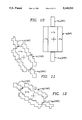
- FIG. 5 is graphical representation of a first kernel function that is convolved with image data for determining blob responses
- FIG. 6 is a graphical representation of a second kernel function that is convolved with image data for determining ganglia responses
- FIGS. 7 to 12 are graphical representations of kernel functions that are convolved with ganglia responses for determining simple responses and corresponding end-stop responses for a respective angular orientation for each figure;
- FIGS. 13 to 16 together comprise a flowchart of a procedure for operating a digital computer system for performing the preferred method of recognizing the presence, position, and orientation of a pointing finger as introduced in FIG. 4;
- FIG. 17 shows a multi-processor system for computing convolutions.
- the data input terminal includes a conventional video display 21 and keyboard 22 set upon a desk or work table 23.
- the data input terminal further includes a video camera 24 aimed at an image area 25 of the surface of the desk 23 over which a human user 26 can move his finger into.
- This image area 25 is located, for example in the position at which a conventional "mouse" (not shown) otherwise might be used.
- the data input terminal 20 uses the video camera 24 to obtain an image including the user's hand 27, and the input terminal recognizes the presence, position and orientation of a pointing finger in the image in order to replace the data input function of the conventional "mouse".
- the data input terminal 20 responds to recognition of the presence and position of the user's pointing finger 28 by displaying a cursor 29 at a position on a video display screen 30 corresponding to the position of the user's pointing finger over the image area 25.
- the cursor 29 has been moved to a desired location of the video screen 30, the user 26 may use his or her other hand 31 to activate the space bar 32 or another key on the keyboard 22 so that the cursor coordinates at that time are passed to the application program.
- the user could enter coordinate information for a graphics application, or select windows, pop-up windows, or interactively adjust parameters for the application program.
- the application program could also use the orientation of the user's pointing finger 28 to select options or adjust parameters.
- the application program uses the angle of the user's finger (i.e., whether the finger points outward or right or left with respect to the user 26) to indicate a selected position on a bar graph, and the selected position is entered when the user 26 strikes a key on the keyboard.
- This technique could be used to enter discrete selections in lieu of the conventional push-buttons on a "mouse" (not shown), and it could also be used to enter a variable selection or provide a variable interactive control input for an application.
- the application program could use the finger angle to adjust a "slider" on a bar graph representing a set point for a control meter, with the direction of the change following the pivoting of the user's finger.
- a displayed control parameter could be increased or decreased at a rate depending on how far the angle of the pointing finger deviates from an approximate outward position.
- the user for example, could quickly adjust "key click" volume, or control the speed of a motor (not shown) by rotating his or her finger in the most intuitive way.
- the data terminal 20 may determine the angular orientation of the user's finger 28 regardless of the position of the user's hand in the image area 25. Therefore, the user need not worry about keeping his or her hand 27 in any particular position, and the user may think more about the application program and its data and less about the manipulation of a data input device.
- the video camera 24 provides a video signal that is sampled by an analog-to-digital converter 41 to provide image data representing samples (i.e., pixels) of the image (from the image area 25) at spaced locations in the image.
- the video camera for example, is a black-and-white camera, and the video signal is sampled by the analog-to-digital converter to provide a "frame" of 128 ⁇ 128 pixels, each of which is represented by an 8-bit value.
- the 8-bit value is the "luminance" or grayscale of the image.
- a color video camera could be used and color information could be processed, which could aid in distinguishing fingers of different users, or an aid in picking out the finger from extraneous background objects (not shown) that might be found on a cluttered desk.
- Color processing would require an increase in memory by a factor of about three, if the color information were processed using about the same resolution as the luminance information.
- the user's finger 28 has good contrast against the surface of the desk 23 in the image area 25 of FIG. 1.
- a black or white pad (not shown) of a size somewhat greater than the viewing area may be placed on the desk 23 in registration with the viewing area 25.
- the "parity" of the video signal is a factor to consider, because the black-and-white video signal has a different polarity for a light hand on a dark background than a dark hand on a light background.
- the preferred method for recognizing a finger involves convolving the image data with a plurality of functions, and then performing some "threshold comparison" operations to detect the presence, position and angular orientation of a finger in the image.
- the convolutions are not sensitive to parity, but the "threshold comparisons" are. Detection of fingers of both possible parities could therefore be performed with only a modest increase in computation. Alternatively, for recognizing the user's finger 28 in the fastest possible time, the "threshold comparisons" are performed for a predetermined parity.
- the predetermined parity could be easily selected by selecting an inverted video signal (e.g., using an analog inverting amplifier [not shown] and a switch [not shown] to select either the input or output of the analog inverting amplifier), by selectively complementing the image data (for example by a bank of eight exclusive-OR gates [not shown], one for each wire [not shown] of an eight-bit data bus conveying the image data) , or else the program steps for the threshold comparisons, as set out below, could be selected for a desired polarity (e.g., a less than comparison to a low threshold is replaced with a greater than comparison to a high threshold).
- a desired polarity e.g., a less than comparison to a low threshold is replaced with a greater than comparison to a high threshold.
- the image data are fed to an object recognition computer 42.
- the object recognition computer is a programmable multi-processor parallel architecture computer having the capability of performing multiple vector scalar product operations simultaneously.
- a dedicated image processing computer could be constructed and used for the object recognition computer 42 (for example, using a pipeline organization suggested by FIG. 4 below)
- a programmable multi-processor parallel architecture computer would permit the object recognition computer 42 to be used for other application programs (such as for voice recognition, spectrum analysis, and solving field equations).
- a programmable multi-processor parallel architecture computer could be built in such a fashion as to more easily perform the two-dimensional convolutions used for the preferred method of the present invention, as discussed below with reference to FIG. 17.
- the computer terminal 20 has a separate "work station” computer that controls the display 21 in response to the keyboard 22 under the control of an application program or an operating system.
- the object recognition computer 42 could be fabricated on a circuit board to be placed into the housing (44 in FIG. 1) of the work-station computer 43.
- the object recognition computer 42 for example, sends an interrupt signal to the work-station computer when the presence of a pointing finger 28 is detected in the image area (25 in FIG. 1), and also sends coordinates of the pointing finger and the angle of the pointing finger.
- FIG. 3 there is shown a flow diagram illustrating the basic method of the present invention for recognizing an occurrence of a predefined object in an image.
- image data 51 are received from an image data source such as a video camera 52, a document scanner 53, disc memory 54, or other source such as a video tape player (not shown) or other computers (not shown) in a computer network (not shown).
- image data are convolved with a set of predefined "kernel" functions to analyze the image data into occurrences of predefined elementary features 55.
- the elementary features include, for example, blobs indicating regions of neighboring spaced locations, ganglia indicating edges of objects in the image, simples indicating lines in the image, complexes indicating terminated line segments in the image, and curves in the image.
- ganglia indicating edges of objects in the image
- simples indicating lines in the image
- complexes indicating terminated line segments in the image
- curves in the image The terms “ganglia”, “simples” and “complexes” are taken from human anatomy, where they are used in a similar fashion to denote nerve cells that are believed to resolve an image on the retina of the eye into nerve impulses responsive to the respective elementary features in the image on the retina.
- the elementary features are examined for an occurrence of a predefined combination of occurrences of the elementary features that is characteristic of the predefined object.
- objects of interest include fingers, hurricanes in weather satellite images, calcifications in mammogram images, cracks in X-ray images, and numbers on the backs of sports uniforms during the televising of a game.
- an application program will require information about the occurrence that is most likely to be a particular object of interest.
- the objects are compared and one is selected, and a report 57 is made of the selected object, such as the object's position in the image, and the object's orientation provided that the object is asymmetrical.
- the comparison, selection and determination of the object's position and orientation is based on the numerical values of the convolutions computed to analyze the image data into the occurrences of the predefined elementary features.
- the selection of objects could also be performed on the basis of color when the image includes color information, and on a previous identification of an object at a similar position and orientation in a previous image frame in a series of image frames taken at spaced instants in time. In the last case, for example, it is assumed that the acceleration of the object is limited, so that the object should follow a trajectory.
- the pointing finger should have some movement when the user desires to use it for data entry into the computer terminal. Therefore, negative feedback can be used at any point in the object detection process to reduce the contribution from non-moving objects that might be found on a cluttered desk. Non-moving finger-like objects in the image area 25 will not be recognized as a pointing finger. Moreover, as long as the pointing finger is kept moving, its contrast will appear to be higher than non-moving objects. This allows the data input terminal 20 in FIG. 1 to work in a real-world environment.
- FIG. 4 there is shown a flow diagram of the preferred data flow through the object recognition computer 42 of FIG. 2 for recognizing a pointing finger.
- Image data 61 from the analog-to-digital converter 41 is initially stored in an 128 ⁇ 128 ⁇ 8-bit array, and is directly convolved with a first kernel function k 1 to determine blob responses 62.
- This first kernel function k 1 is graphically illustrated in FIG. 5, and it includes non-zero values in a 25 ⁇ 25 pixel square array of 1's, surrounded by a 6-pixel wide border area of -1's. The size of 25 ⁇ 25 array of +1's in the kernel k 1 is chosen to match the size of the user's fist.
- a blob response is not computed at every pixel location, but instead is computed at every 4th pixel location in both the x and y directions (i.e., the blob response is "sub-sampled").
- the blob responses therefore can be stored in a 32 ⁇ 32 ⁇ 8 bit array after scaling.
- the convolution of the image data with the kernel k 1 in effect is a low-pass spatial filtering operation, so that the blob responses represent a blurred version of the image.
- the image data 61 is also directly convolved with a second kernel function k 2 to determine ganglia responses 65.
- the kernel k 2 is shown in FIG. 6 and it includes non-zero values in a 9 ⁇ 9 pixel array, each having a respective 10-bit value.
- the numerical values for the kernel k 2 were determined as the difference between two gaussian functions, to optimize edge detection of a pointing finger having a width of about 4 pixels.
- a ganglia response is computed for each pixel, and each response is scaled for storage in a 128 ⁇ 128 ⁇ 8-bit array.
- the ganglia responses 65 are convolved directly with six kernel functions k 3 to k 8 to compute simple responses 66 to 71 indicating responses to straight lines in the image at particular locations and having respective angular orientations of 30° increments (i.e., 0°, 30°, . . . , 150°). For each orientation, there is a simple response corresponding to every pixel, so that the simple responses are scaled and then stored in a 6 ⁇ 128 ⁇ 128 ⁇ 8-bit array. As shown in FIG.
- the non-zero portion of the kernel k 3 includes a 13 ⁇ 4 array 169 of 1's, corresponding to the portion of a pointing finger extending from a fist, surrounded by flanking regions 170 and 171, each of which includes a 13 ⁇ 2 array of -1's.
- the simple ganglia responses 65 are convolved with "end stop” kernel functions k 9 to k 20 and combined with respective simple responses 66 to 68 to obtain complex responses 72 to 77.
- the "end stop” kernel functions k 9 to k 20 are shown in FIGS. 7 to 10 along with the kernel functions of their corresponding simple responses.
- Each "end stop" kernel function k 9 to k 20 defines a region of 10 pixels, about 5 pixels long and about 2 pixels wide, located off an end of the kernel for its corresponding simple response.
- a complex response for a particular angular orientation resembles the simple response along the same line, but the complex response also requires that the line not be too long: the line must be stopped at a respective end location relative to the central location of the simple response.
- the complex response is computed by first comparing the simple response to a first predetermined threshold, and for each simple response that exceeds the threshold, computing each of the two respective "end stop” responses associated with the simple response.
- the "end stop” responses are computed, for example, by inspecting each of the ganglia responses in the respective "end stop” region, and counting the number of such ganglia responses that are less than a certain minimum value. Then the "end stop” response is compared to a second predetermined threshold, and for each "end stop” response that is greater than the second predetermined threshold, setting its respective complex response to the value of its corresponding simple response.
- a strong horizontal complex response directed at 0° thus indicates that there is a strong horizontal simple response at the same pixel, and also no significant ganglia responses displaced to the right; similarly, a strong horizontal complex response directed at 180° indicates that there is a strong horizontal simple response at the same pixel, and also no significant ganglia responses displaced to the left.
- a strong horizontal complex response directed at 180° indicates that there is a strong horizontal simple response at the same pixel, and also no significant ganglia responses displaced to the left.
- each simple response there are two complex responses; there are six simple responses and 12 complex responses for each pixel, assuming that the simple responses for each pixel have respective angular orientations that are at multiples of 30°.
- the blob responses 62 are combined with complex responses 72 to 77 to provide finger responses 81 to 86.
- a finger response is zero unless there is the simultaneous occurrence of a substantial complex response (indicating a finger-like object) and, displaced in the opposite angular direction of the complex response, a substantial blob response (indicating a fist-like object). If such a combination of a complex response and a blob response is found, then the value of the finger response is set to the complex response; otherwise, the value of the finger response is set to zero.
- the finger responses are compared to select the finger response that has the maximum value. When the maximum value exceeds a predetermined threshold, the presence of the finger is reported by an interrupt to the application program to update the position of the cursor on the display screen.
- an interpolation can be performed between the position of the maximum finger response and the neighboring finger response at the same angular orientation having the next largest response to provide a more precise position of the user's pointing finger.
- an interpolation can be performed between the maximum finger response and the finger response at the same position and the one of the two neighboring angular orientations having the next largest response to provide a more precise angular orientation of the user's pointing finger.
- the finger recognition process of FIG. 4 is repeated with a new frame of image data.
- FIG. 13 there is shown a flowchart of a procedure for operating a digital computer to perform the finger recognition process of FIG. 4.
- a first frame buffer C(i,j) is cleared. This first frame buffer C(i,j) is used for performing a time integration of the image data at the same pixels between successive frames to extract image data that remains constant with time.
- step 102 a new frame of image data are loaded into a second frame buffer IMAGE(i,j). Then in step 103 the blob responses are computed by convolving the image data in the second frame buffer IMAGE(i,j) with the first kernel function k 1 , while sub-sampling in each of the x and y directions by a factor of 4.
- step 104 the image component that remains constant with time is computed by performing a "leaky bucket" accumulation of the image data into the first frame buffer.
- the value in the first frame buffer C(i,j) is decreased by a fraction of the original value and increased by a fraction of the new image value.
- the fractions are chosen to be a power of two, so that the fractions correspond to an arithmetic shift operation.
- step 105 the image data that remains constant with time is suppressed or removed from the image data in the second frame buffer IMAGE(i,j) by subtracting the values in the first frame buffer C(i,j) from the corresponding values in the second frame buffer IMAGE(i,j) and storing the differences in the second frame buffer IMAGE(i,j).
- This is done to suppress the ganglia, simple, and complex responses that are constant with time.
- the blob responses are computed from the image data before constant image components are removed, so that a moving pointing finger will be recognized even though the moving pointing finger extends from a non-moving fist.
- step 106 the ganglia responses are computed by convolving the image data in the second frame buffer IMAGE(i,j) with the second kernel function k 2 .
- step 107 the simple responses at each of the six angular inclinations are computed by convolving the ganglia responses with each of the six kernel functions k 3 to k 8 .
- step 108 the complex responses are computed for each of the twelve angular directions by computing the two end-stop responses for each simple response exceeding a first predetermined threshold TH1, and for each end-stop response that is greater than a second predetermined threshold TH2, setting the corresponding complex response to the simple response, and otherwise setting the corresponding complex response to zero.
- step 109 the finger responses are computed for each complex response that is greater than zero by searching for a blob response that exceeds a third predetermined threshold TH3 and is located within the neighborhood of the blob response closest to the pixel (s,t) that is a predetermined distance r (about 19 pixels) from the pixel of the complex response in the direction opposite of the direction ⁇ of the complex response. Then in step 110 the maximum finger response is found by scanning the finger responses and performing comparison operations.
- step 111 the maximum finger response is compared to zero, and if it is zero, then execution loops back to step 102 to process a new frame of image data because a finger has not been found in the present frame of image data. Otherwise, in step 113, the finger position is computed by an interpolation between the position (MI, MJ) of the maximum finger response MAXRESP and the neighboring finger response at the same angular orientation (MG, MH) having the next largest response NXTMAX to provide a more precise position (POSX, POSY) of the user's pointing finger.
- step 114 the finger responses PRESP and NRESP are obtained at the same pixel as the maximum finger response but at the two neighboring angular orientations (PG, PH) and (NG, NH).
- step 115 an angular interpolation is performed between the maximum finger response and the larger one of the two neighboring responses PRESP and NRESP to provide a more precise angular orientation of the user's pointing finger.
- step 116 the presence of the user's pointing finger is reported by an interrupt to the application program, and the application program is also provided with the interpolated position and angular orientation computed for the user's pointing finger.
- Appendix 1 A specific example of a computer program for operating a digital computer to perform the finger recognition process of FIG. 4 is included in Appendix 1.
- the computer program in Appendix 1 was written for a "DECstation 5000" brand workstation. It requires about 29.2 seconds to process a frame of 128 ⁇ 128 ⁇ 8-bit image data, and the blob, ganglia, and simple convolutions take 28.9 seconds of the 29.2 seconds total. For near real-time processing, only the simples for 0° angular orientation can be computed. For real-time operation in the fashion described above with respect to FIG. 1 using present computer technology, however, a multi-processor computer should be used.
- FIG. 17 there is shown a multi-processor system that could be used for the object recognition computer 42 in FIG. 1.
- Real-time operation of the computer terminal 20 in FIG. 1 requires a minimum number of arithmetic operations per image frame, and at a given frame rate (such as the standard 30 frames per second) a minimum number of arithmetic computations per second is established.
- This minimum number of arithmetic computations per second requires at least a certain number N of processors 121 to be included in the object recognition computer 42.
- each processor in the object recognition computer 42 has a portion of shared random access memory 122, and the combinations of portions of the shared random access memory comprise at least one frame buffer. The combination of each processor with its shared random access memory makes up a separate processor system. Therefore, in the object recognition computer 42 in FIG. 17, there are N such processor systems 123, 124, 125.
- each processor reads data located in a respective preassigned region of the frame buffer, then it is necessary for the results of at least one of the processors to be written to the image buffer memory of another one of the processors.
- one address bus 126 and one data bus 127 are provided for permitting each of the processors to transmit data to all of the other processors. Since the buses 126, 127 are shared among all of the processors, a priority encoder 128 is provided to grant priority to a selected processor requesting access to the buses when there are simultaneous requests for data transmission over the buses.
- the result of a convolution to be stored at each pixel will be computed entirely by only one of the processors. This condition ensures that the bus need not transmit any partial vector scalar products from one processor system to another processor system.
- the convolution of an entire frame with a single kernel will be computed by at least two processors operating in parallel.
- the result of a convolution to be stored at each pixel will be computed by a respective processor by performing a vector scalar product of the convolution kernel with a vector read from the processor's shared random access memory, and then the result will be "broadcast" over the shared data bus 127.
- the maximum limit of processing speed could be increased beyond that needed for the computer terminal 20 of FIG. 1 by adding additional shared buses and corresponding frame buffers of shared memory for simultaneously broadcasting the results of the blob, ganglia, and simple convolutions on separate respective buses.
- the processor 121 addresses the shared memory by asserting a memory bank select signal or high-order address on a line 131.
- gates 132, 133, and 134 enable a data bus transmission gate 135 unless priority for a "global" write operation has been granted by the priority encoder 128 to another processor and an address decoder 119 determines that the "global" write operation addresses the shared random access memory 122 for the processor system 123, in which case the processor 121 is stalled by a gate 136.
- gates 137 and 138 enable an address bus transmission gate 139, unless priority for a "global" write operation has been granted by the priority encoder 128 to another processor and the address decoder 119 determines that the "global" write operation addresses the shared random access memory 122 for the processor system 123.
- gates 140, 137 and 138 enable an address bus transmission gate 139, unless priority for a "global" write operation has been granted by the priority encoder 128 to another processor, in which case the processor 121 is stalled by gates 141 and 136.
- transmission gates 142 and 143 are enabled to assert the write address and write data on the shared address bus 126 and shared data bus 127.
- a gate 144 When a write address and write data are asserted on the shared address and data buses 126 and 127 and the address decoder 119 determines that the address on the shared address bus 126 falls within the address range of the shared memory 122 for the processor 121, then a gate 144 enables the shared memory 122 to perform a write operation. Moreover, when the write operation is initiated by a processor other than the processor 121, then a gate 145 enables transmission gates 146 and 147 to assert upon the shared memory 122 the address from the shared address bus 126 and the data from the shared data bus 127.
- a massively-parallel processor of conventional organization could be used, in which the processors are organized into an array and a multiplicity of data links are provided for inter-processor communication.
- each processor could be assigned the task of performing all of the partial vector scalar products associated with the convolutions upon a pre-assigned region of an input frame buffer.
- Each partial vector product would then be transmitted to a processor assigned to a region of an output frame buffer at which the complete vector product would be stored; that processor would sum the partial vector products to form the complete vector product, and store it in the output frame buffer.
- a voice recognition system could replace the keyboard 22 to provide entirely "hands free" operation.
- the voice recognition system could recognize a command to enter the coordinates of the user's pointing finger, or a command to enter a selection based on the angle of the user's pointing finger, or other commands in lieu of the push-buttons on a conventional "mouse.”
- two or three video cameras could be used to obtain images of the user's finger from different directions to obtain the coordinates and angle of the user's finger in three-dimensional space.
- Three cameras for example directed along three orthogonal axes, could capture images that would be orthogonal projections of the user's pointing finger and would allow the angle of the pointing finger to be determined from any orientation of the finger in three-dimensional space.
- This three-dimensional finger-pointing information would be very useful to enter coordinate information, for example, to a three-dimensional graphics system using a three-dimensional video display. The user could then point to features of a three-dimensional virtual image.
- the three-dimensional video display could be a conventional color cathode-ray tube in which "right" and “left” stereoscopic images are displayed in respective red and blue colors and viewed through conventional 3-D glasses having respective red and blue color filters for the right and left eyes, or the three-dimensional display could be a stereoscopic "heads-up" display worn by the user.
- the basic object recongnition method of the present invention can use various sources of image data, as shown and described above with reference to FIG. 3.
- a method of operating a digital computer to recognize an occurrence of a predefined object in an image is based upon the human visual system, which has evolved to a high state of perfection, and has a wide range of applicability. Moreover, the method can be carried out in real-time by a multi-processor computer system.
- the method permits a data input terminal to recognize the presence, position, and orientation of a pointing finger, to eliminate the need for data input devices such as "mice” or "joysticks.” Therefore a user can direct an application program in the most natural way, without the distraction of manipulating a data input device.
Abstract
Description
Claims (29)
Priority Applications (4)
| Application Number | Priority Date | Filing Date | Title |
|---|---|---|---|
| US07/722,082 US5168531A (en) | 1991-06-27 | 1991-06-27 | Real-time recognition of pointing information from video |
| PCT/US1992/004285 WO1993000657A1 (en) | 1991-06-27 | 1992-05-21 | Real-time recognition of pointing information from video |
| EP92914615A EP0591412B1 (en) | 1991-06-27 | 1992-05-21 | Real-time recognition of pointing information from video |
| DE69217550T DE69217550T2 (en) | 1991-06-27 | 1992-05-21 | REAL-TIME DETECTION OF POINTER INFORMATION BY VIDEO |
Applications Claiming Priority (1)
| Application Number | Priority Date | Filing Date | Title |
|---|---|---|---|
| US07/722,082 US5168531A (en) | 1991-06-27 | 1991-06-27 | Real-time recognition of pointing information from video |
Publications (1)
| Publication Number | Publication Date |
|---|---|
| US5168531A true US5168531A (en) | 1992-12-01 |
Family
ID=24900439
Family Applications (1)
| Application Number | Title | Priority Date | Filing Date |
|---|---|---|---|
| US07/722,082 Expired - Lifetime US5168531A (en) | 1991-06-27 | 1991-06-27 | Real-time recognition of pointing information from video |
Country Status (4)
| Country | Link |
|---|---|
| US (1) | US5168531A (en) |
| EP (1) | EP0591412B1 (en) |
| DE (1) | DE69217550T2 (en) |
| WO (1) | WO1993000657A1 (en) |
Cited By (165)
| Publication number | Priority date | Publication date | Assignee | Title |
|---|---|---|---|---|
| EP0613079A1 (en) * | 1993-02-23 | 1994-08-31 | ZELTRON S.p.A. | Man-machine interface system |
| US5381158A (en) * | 1991-07-12 | 1995-01-10 | Kabushiki Kaisha Toshiba | Information retrieval apparatus |
| DE4339161A1 (en) * | 1993-08-09 | 1995-02-16 | Siemens Ag | Method for following movements of a human hand in a time series of digital colour images |
| US5517210A (en) * | 1993-02-26 | 1996-05-14 | Hitachi, Ltd. | Multi-scan type display system with pointer function |
| US5594469A (en) * | 1995-02-21 | 1997-01-14 | Mitsubishi Electric Information Technology Center America Inc. | Hand gesture machine control system |
| US5617312A (en) * | 1993-11-19 | 1997-04-01 | Hitachi, Ltd. | Computer system that enters control information by means of video camera |
| US5625717A (en) * | 1992-06-24 | 1997-04-29 | Mitsubishi Denki Kabushiki Kaisha | Image processing device for processing grey level images |
| US5677700A (en) * | 1993-12-23 | 1997-10-14 | Schwalba; Henrik | Apparatus and method for achieving optical data protection and intimacy for users of computer terminals |
| GB2315859A (en) * | 1996-07-29 | 1998-02-11 | Mitel Corp | Input device simulating touch screen |
| US5736976A (en) * | 1995-02-13 | 1998-04-07 | Cheung; Nina T. | Computer data entry apparatus with hand motion sensing and monitoring |
| US5767842A (en) * | 1992-02-07 | 1998-06-16 | International Business Machines Corporation | Method and device for optical input of commands or data |
| US5821922A (en) * | 1997-05-27 | 1998-10-13 | Compaq Computer Corporation | Computer having video controlled cursor system |
| US5864334A (en) * | 1997-06-27 | 1999-01-26 | Compaq Computer Corporation | Computer keyboard with switchable typing/cursor control modes |
| WO1999021122A1 (en) * | 1997-10-22 | 1999-04-29 | Ascent Technology, Inc. | Voice-output reading system with gesture-based navigation |
| US5900863A (en) * | 1995-03-16 | 1999-05-04 | Kabushiki Kaisha Toshiba | Method and apparatus for controlling computer without touching input device |
| WO1999035633A2 (en) * | 1998-01-06 | 1999-07-15 | The Video Mouse Group | Human motion following computer mouse and game controller |
| US5959612A (en) * | 1994-02-15 | 1999-09-28 | Breyer; Branko | Computer pointing device |
| US5982352A (en) * | 1992-09-18 | 1999-11-09 | Pryor; Timothy R. | Method for providing human input to a computer |
| US5990865A (en) * | 1997-01-06 | 1999-11-23 | Gard; Matthew Davis | Computer interface device |
| US6002808A (en) * | 1996-07-26 | 1999-12-14 | Mitsubishi Electric Information Technology Center America, Inc. | Hand gesture control system |
| WO2000002187A1 (en) * | 1998-07-01 | 2000-01-13 | Deluca Michael J | Stereoscopic user interface method and apparatus |
| US6043805A (en) * | 1998-03-24 | 2000-03-28 | Hsieh; Kuan-Hong | Controlling method for inputting messages to a computer |
| WO2000021023A1 (en) * | 1998-10-07 | 2000-04-13 | Intel Corporation | Controlling a pointer using digital video |
| US6115482A (en) * | 1996-02-13 | 2000-09-05 | Ascent Technology, Inc. | Voice-output reading system with gesture-based navigation |
| US6137527A (en) * | 1996-12-23 | 2000-10-24 | General Electric Company | System and method for prompt-radiology image screening service via satellite |
| US6147678A (en) * | 1998-12-09 | 2000-11-14 | Lucent Technologies Inc. | Video hand image-three-dimensional computer interface with multiple degrees of freedom |
| US6266435B1 (en) * | 1993-09-29 | 2001-07-24 | Shih-Ping Wang | Computer-aided diagnosis method and system |
| US6281878B1 (en) | 1994-11-01 | 2001-08-28 | Stephen V. R. Montellese | Apparatus and method for inputing data |
| US6292173B1 (en) * | 1998-09-11 | 2001-09-18 | Stmicroelectronics S.R.L. | Touchpad computer input system and method |
| US20020002490A1 (en) * | 2000-03-29 | 2002-01-03 | George Gerpheide | Personalized computer peripheral |
| US6346929B1 (en) * | 1994-04-22 | 2002-02-12 | Canon Kabushiki Kaisha | Display apparatus which detects an observer body part motion in correspondence to a displayed element used to input operation instructions to start a process |
| US20020036617A1 (en) * | 1998-08-21 | 2002-03-28 | Timothy R. Pryor | Novel man machine interfaces and applications |
| US6373961B1 (en) | 1996-03-26 | 2002-04-16 | Eye Control Technologies, Inc. | Eye controllable screen pointer |
| US6373235B1 (en) | 1999-05-04 | 2002-04-16 | Clifford A. Barker | Apparatus and method for determining the position and motion of an object and for precise measurement of phase-related values |
| US20020070970A1 (en) * | 2000-11-22 | 2002-06-13 | Wood Susan A. | Graphical user interface for display of anatomical information |
| US20020071277A1 (en) * | 2000-08-12 | 2002-06-13 | Starner Thad E. | System and method for capturing an image |
| US6417969B1 (en) | 1988-07-01 | 2002-07-09 | Deluca Michael | Multiple viewer headset display apparatus and method with second person icon display |
| WO2002056240A1 (en) * | 2000-11-22 | 2002-07-18 | R2 Technology, Inc. | Graphical user interface for display of anatomical information |
| US6434255B1 (en) * | 1997-10-29 | 2002-08-13 | Takenaka Corporation | Hand pointing apparatus |
| US6459769B1 (en) * | 1999-05-03 | 2002-10-01 | Sherwood Services Ag | Movable miniature multi-leaf collimator |
| US6478432B1 (en) | 2001-07-13 | 2002-11-12 | Chad D. Dyner | Dynamically generated interactive real imaging device |
| US6498471B2 (en) | 1999-05-04 | 2002-12-24 | A. Clifford Barker | Apparatus and method for direct digital measurement of electrical properties of passive components |
| US6567078B2 (en) * | 2000-01-25 | 2003-05-20 | Xiroku Inc. | Handwriting communication system and handwriting input device used therein |
| US20030095697A1 (en) * | 2000-11-22 | 2003-05-22 | Wood Susan A. | Graphical user interface for display of anatomical information |
| US20030095206A1 (en) * | 2001-09-10 | 2003-05-22 | Wredenhagen G. Finn | System and method for reducing noise in images |
| US6574357B2 (en) * | 1993-09-29 | 2003-06-03 | Shih-Ping Wang | Computer-aided diagnosis method and system |
| US6614422B1 (en) * | 1999-11-04 | 2003-09-02 | Canesta, Inc. | Method and apparatus for entering data using a virtual input device |
| US6630924B1 (en) * | 2000-02-22 | 2003-10-07 | International Business Machines Corporation | Gesture sensing split keyboard and approach for capturing keystrokes |
| US20040001182A1 (en) * | 2002-07-01 | 2004-01-01 | Io2 Technology, Llc | Method and system for free-space imaging display and interface |
| US20040005091A1 (en) * | 2002-06-20 | 2004-01-08 | Makoto Maruya | Topographic measurement using stereoscopic picture frames |
| US20040027365A1 (en) * | 2002-08-07 | 2004-02-12 | Sayers Craig P. | Controlling playback of a temporal stream with a user interface device |
| US6697721B2 (en) * | 2000-06-08 | 2004-02-24 | A.V.B.A. Engineers And Services (93) Ltd. | Safety devices for use in motor vehicles |
| US6738041B2 (en) | 1999-10-29 | 2004-05-18 | Intel Corporation | Using video information to control cursor position |
| US20040095315A1 (en) * | 2002-11-12 | 2004-05-20 | Steve Montellese | Virtual holographic input method and device |
| US6750848B1 (en) * | 1998-11-09 | 2004-06-15 | Timothy R. Pryor | More useful man machine interfaces and applications |
| US6791531B1 (en) * | 1999-06-07 | 2004-09-14 | Dot On, Inc. | Device and method for cursor motion control calibration and object selection |
| US20040218269A1 (en) * | 2002-01-14 | 2004-11-04 | Divelbiss Adam W. | General purpose stereoscopic 3D format conversion system and method |
| US20050104850A1 (en) * | 2003-11-17 | 2005-05-19 | Chia-Chang Hu | Cursor simulator and simulating method thereof for using a limb image to control a cursor |
| US6900790B1 (en) * | 1998-03-17 | 2005-05-31 | Kabushiki Kaisha Toshiba | Information input apparatus, information input method, and recording medium |
| US20050166163A1 (en) * | 2004-01-23 | 2005-07-28 | Chang Nelson L.A. | Systems and methods of interfacing with a machine |
| US20050188181A1 (en) * | 2004-02-05 | 2005-08-25 | Eugene Mar | Data bus configuration |
| US6943774B2 (en) * | 2001-04-02 | 2005-09-13 | Matsushita Electric Industrial Co., Ltd. | Portable communication terminal, information display device, control input device and control input method |
| US20050219240A1 (en) * | 2004-04-05 | 2005-10-06 | Vesely Michael A | Horizontal perspective hands-on simulator |
| WO2005098517A2 (en) * | 2004-04-05 | 2005-10-20 | Vesely Michael A | Horizontal perspective hand-on simulator |
| US20050248566A1 (en) * | 2004-04-05 | 2005-11-10 | Vesely Michael A | Horizontal perspective hands-on simulator |
| US20050264858A1 (en) * | 2004-06-01 | 2005-12-01 | Vesely Michael A | Multi-plane horizontal perspective display |
| WO2005091125A3 (en) * | 2004-03-22 | 2005-12-15 | Eyesight Mobile Tech Ltd | System and method for inputing user commands to a processor |
| US20060097985A1 (en) * | 2004-11-08 | 2006-05-11 | Samsung Electronics Co., Ltd. | Portable terminal and data input method therefor |
| US20060190836A1 (en) * | 2005-02-23 | 2006-08-24 | Wei Ling Su | Method and apparatus for data entry input |
| US7098891B1 (en) * | 1992-09-18 | 2006-08-29 | Pryor Timothy R | Method for providing human input to a computer |
| WO2006092399A1 (en) * | 2005-03-04 | 2006-09-08 | Siemens Aktiengesellschaft | Method for marking an image content, and marking device |
| US20060202953A1 (en) * | 1997-08-22 | 2006-09-14 | Pryor Timothy R | Novel man machine interfaces and applications |
| US20070214462A1 (en) * | 2006-03-08 | 2007-09-13 | Navisense. Llc | Application programming interface (api)for sensory events |
| US20070220437A1 (en) * | 2006-03-15 | 2007-09-20 | Navisense, Llc. | Visual toolkit for a virtual user interface |
| US7342574B1 (en) * | 1999-10-29 | 2008-03-11 | Ricoh Company, Ltd. | Method and apparatus for inputting information including coordinate data |
| US20080100572A1 (en) * | 2006-10-31 | 2008-05-01 | Marc Boillot | Touchless User Interface for a Mobile Device |
| US20080122799A1 (en) * | 2001-02-22 | 2008-05-29 | Pryor Timothy R | Human interfaces for vehicles, homes, and other applications |
| US20080129704A1 (en) * | 1995-06-29 | 2008-06-05 | Pryor Timothy R | Multipoint, virtual control, and force based touch screen applications |
| US20080273755A1 (en) * | 2007-05-04 | 2008-11-06 | Gesturetek, Inc. | Camera-based user input for compact devices |
| US20090085881A1 (en) * | 2007-09-28 | 2009-04-02 | Microsoft Corporation | Detecting finger orientation on a touch-sensitive device |
| US20090267921A1 (en) * | 1995-06-29 | 2009-10-29 | Pryor Timothy R | Programmable tactile touch screen displays and man-machine interfaces for improved vehicle instrumentation and telematics |
| US20090284469A1 (en) * | 2008-05-16 | 2009-11-19 | Tatung Company | Video based apparatus and method for controlling the cursor |
| US20090296991A1 (en) * | 2008-05-29 | 2009-12-03 | Anzola Carlos A | Human interface electronic device |
| US20100020037A1 (en) * | 2008-07-25 | 2010-01-28 | Tomoya Narita | Information processing apparatus and information processing method |
| US20100103103A1 (en) * | 2008-08-22 | 2010-04-29 | Palanker Daniel V | Method And Device for Input Of Information Using Visible Touch Sensors |
| US20100190610A1 (en) * | 2000-03-07 | 2010-07-29 | Pryor Timothy R | Camera based interactive exercise |
| US20100302165A1 (en) * | 2009-05-26 | 2010-12-02 | Zienon, Llc | Enabling data entry based on differentiated input objects |
| US20110037725A1 (en) * | 2002-07-03 | 2011-02-17 | Pryor Timothy R | Control systems employing novel physical controls and touch screens |
| US7907167B2 (en) | 2005-05-09 | 2011-03-15 | Infinite Z, Inc. | Three dimensional horizontal perspective workstation |
| US20110090147A1 (en) * | 2009-10-20 | 2011-04-21 | Qualstar Corporation | Touchless pointing device |
| US20110122130A1 (en) * | 2005-05-09 | 2011-05-26 | Vesely Michael A | Modifying Perspective of Stereoscopic Images Based on Changes in User Viewpoint |
| US20110187706A1 (en) * | 2010-01-29 | 2011-08-04 | Vesely Michael A | Presenting a View within a Three Dimensional Scene |
| US8018579B1 (en) * | 2005-10-21 | 2011-09-13 | Apple Inc. | Three-dimensional imaging and display system |
| USRE42794E1 (en) | 1999-12-27 | 2011-10-04 | Smart Technologies Ulc | Information-inputting device inputting contact point of object on recording surfaces as information |
| US8055022B2 (en) | 2000-07-05 | 2011-11-08 | Smart Technologies Ulc | Passive touch system and method of detecting user input |
| US8077147B2 (en) | 2005-12-30 | 2011-12-13 | Apple Inc. | Mouse with optical sensing surface |
| US8089462B2 (en) | 2004-01-02 | 2012-01-03 | Smart Technologies Ulc | Pointer tracking across multiple overlapping coordinate input sub-regions defining a generally contiguous input region |
| US8094137B2 (en) | 2007-07-23 | 2012-01-10 | Smart Technologies Ulc | System and method of detecting contact on a display |
| US8115753B2 (en) | 2007-04-11 | 2012-02-14 | Next Holdings Limited | Touch screen system with hover and click input methods |
| US8120596B2 (en) | 2004-05-21 | 2012-02-21 | Smart Technologies Ulc | Tiled touch system |
| US8130203B2 (en) | 2007-01-03 | 2012-03-06 | Apple Inc. | Multi-touch input discrimination |
| US20120062736A1 (en) * | 2010-09-13 | 2012-03-15 | Xiong Huaixin | Hand and indicating-point positioning method and hand gesture determining method used in human-computer interaction system |
| US8149221B2 (en) | 2004-05-07 | 2012-04-03 | Next Holdings Limited | Touch panel display system with illumination and detection provided from a single edge |
| US8228304B2 (en) | 2002-11-15 | 2012-07-24 | Smart Technologies Ulc | Size/scale orientation determination of a pointer in a camera-based touch system |
| US8228305B2 (en) | 1995-06-29 | 2012-07-24 | Apple Inc. | Method for providing human input to a computer |
| US8239784B2 (en) | 2004-07-30 | 2012-08-07 | Apple Inc. | Mode-based graphical user interfaces for touch sensitive input devices |
| US8269727B2 (en) | 2007-01-03 | 2012-09-18 | Apple Inc. | Irregular input identification |
| US8274496B2 (en) | 2004-04-29 | 2012-09-25 | Smart Technologies Ulc | Dual mode touch systems |
| US8285791B2 (en) | 2001-03-27 | 2012-10-09 | Wireless Recognition Technologies Llc | Method and apparatus for sharing information using a handheld device |
| US8289299B2 (en) | 2003-02-14 | 2012-10-16 | Next Holdings Limited | Touch screen signal processing |
| US20120268376A1 (en) * | 2011-04-20 | 2012-10-25 | Qualcomm Incorporated | Virtual keyboards and methods of providing the same |
| US8306635B2 (en) | 2001-03-07 | 2012-11-06 | Motion Games, Llc | Motivation and enhancement of physical and mental exercise, rehabilitation, health and social interaction |
| US8314773B2 (en) | 2002-09-09 | 2012-11-20 | Apple Inc. | Mouse having an optically-based scrolling feature |
| US8314775B2 (en) | 1998-01-26 | 2012-11-20 | Apple Inc. | Multi-touch touch surface |
| US8339378B2 (en) | 2008-11-05 | 2012-12-25 | Smart Technologies Ulc | Interactive input system with multi-angle reflector |
| US8381135B2 (en) | 2004-07-30 | 2013-02-19 | Apple Inc. | Proximity detector in handheld device |
| US8384693B2 (en) | 2007-08-30 | 2013-02-26 | Next Holdings Limited | Low profile touch panel systems |
| US8384684B2 (en) | 2007-01-03 | 2013-02-26 | Apple Inc. | Multi-touch input discrimination |
| US8405637B2 (en) | 2008-01-07 | 2013-03-26 | Next Holdings Limited | Optical position sensing system and optical position sensor assembly with convex imaging window |
| US20130082928A1 (en) * | 2011-09-30 | 2013-04-04 | Seung Wook Kim | Keyboard-based multi-touch input system using a displayed representation of a users hand |
| US8432377B2 (en) | 2007-08-30 | 2013-04-30 | Next Holdings Limited | Optical touchscreen with improved illumination |
| US20130135199A1 (en) * | 2010-08-10 | 2013-05-30 | Pointgrab Ltd | System and method for user interaction with projected content |
| US20130139079A1 (en) * | 2011-11-28 | 2013-05-30 | Sony Computer Entertainment Inc. | Information processing device and information processing method using graphical user interface, and data structure of content file |
| US8456451B2 (en) | 2003-03-11 | 2013-06-04 | Smart Technologies Ulc | System and method for differentiating between pointers used to contact touch surface |
| US8456418B2 (en) | 2003-10-09 | 2013-06-04 | Smart Technologies Ulc | Apparatus for determining the location of a pointer within a region of interest |
| US8456447B2 (en) | 2003-02-14 | 2013-06-04 | Next Holdings Limited | Touch screen signal processing |
| US8482535B2 (en) | 1999-11-08 | 2013-07-09 | Apple Inc. | Programmable tactile touch screen displays and man-machine interfaces for improved vehicle instrumentation and telematics |
| US8508508B2 (en) | 2003-02-14 | 2013-08-13 | Next Holdings Limited | Touch screen signal processing with single-point calibration |
| US8576199B1 (en) | 2000-02-22 | 2013-11-05 | Apple Inc. | Computer control systems |
| US8633914B2 (en) * | 2004-06-17 | 2014-01-21 | Adrea, LLC | Use of a two finger input on touch screens |
| US20140035805A1 (en) * | 2009-04-02 | 2014-02-06 | David MINNEN | Spatial operating environment (soe) with markerless gestural control |
| US8654198B2 (en) | 1999-05-11 | 2014-02-18 | Timothy R. Pryor | Camera based interaction and instruction |
| US8692768B2 (en) | 2009-07-10 | 2014-04-08 | Smart Technologies Ulc | Interactive input system |
| US8743076B1 (en) | 1998-05-15 | 2014-06-03 | Lester F. Ludwig | Sensor array touchscreen recognizing finger flick gesture from spatial pressure distribution profiles |
| US20140160013A1 (en) * | 2012-12-10 | 2014-06-12 | Pixart Imaging Inc. | Switching device |
| CN103885572A (en) * | 2012-12-19 | 2014-06-25 | 原相科技股份有限公司 | Switching device |
| US8782566B2 (en) | 2011-02-22 | 2014-07-15 | Cisco Technology, Inc. | Using gestures to schedule and manage meetings |
| US8786529B1 (en) | 2011-05-18 | 2014-07-22 | Zspace, Inc. | Liquid crystal variable drive voltage |
| WO2014113343A1 (en) * | 2013-01-18 | 2014-07-24 | Microsoft Corporation | Controlling a computing-based device using hand gestures |
| US8891817B2 (en) * | 2013-03-15 | 2014-11-18 | Orcam Technologies Ltd. | Systems and methods for audibly presenting textual information included in image data |
| US8894489B2 (en) | 2008-07-12 | 2014-11-25 | Lester F. Ludwig | Touch user interface supporting global and context-specific touch gestures that are responsive to at least one finger angle |
| US8902193B2 (en) | 2008-05-09 | 2014-12-02 | Smart Technologies Ulc | Interactive input system and bezel therefor |
| WO2015010790A1 (en) * | 2013-07-24 | 2015-01-29 | Giesecke & Devrient Gmbh | Method and device for processing value documents |
| USRE45559E1 (en) | 1997-10-28 | 2015-06-09 | Apple Inc. | Portable computers |
| US9123255B2 (en) | 1996-08-13 | 2015-09-01 | Iplearn-Focus, Llc | Computing method and system with detached sensor in a window environment |
| US9152241B2 (en) | 2006-04-28 | 2015-10-06 | Zienon, Llc | Method and apparatus for efficient data input |
| US9158381B2 (en) | 2013-02-25 | 2015-10-13 | Honda Motor Co., Ltd. | Multi-resolution gesture recognition |
| US20150309581A1 (en) * | 2009-04-02 | 2015-10-29 | David MINNEN | Cross-user hand tracking and shape recognition user interface |
| US20150371103A1 (en) * | 2011-01-16 | 2015-12-24 | Eyecue Vision Technologies Ltd. | System and method for identification of printed matter in an image |
| US9239673B2 (en) | 1998-01-26 | 2016-01-19 | Apple Inc. | Gesturing with a multipoint sensing device |
| US9239677B2 (en) | 2004-05-06 | 2016-01-19 | Apple Inc. | Operation of a computer with touch screen interface |
| US9292111B2 (en) | 1998-01-26 | 2016-03-22 | Apple Inc. | Gesturing with a multipoint sensing device |
| US9442607B2 (en) | 2006-12-04 | 2016-09-13 | Smart Technologies Inc. | Interactive input system and method |
| US9448712B2 (en) | 2007-01-07 | 2016-09-20 | Apple Inc. | Application programming interfaces for scrolling operations |
| US9595108B2 (en) | 2009-08-04 | 2017-03-14 | Eyecue Vision Technologies Ltd. | System and method for object extraction |
| US9636588B2 (en) | 2009-08-04 | 2017-05-02 | Eyecue Vision Technologies Ltd. | System and method for object extraction for embedding a representation of a real world object into a computer graphic |
| US9760214B2 (en) | 2005-02-23 | 2017-09-12 | Zienon, Llc | Method and apparatus for data entry input |
| US9764222B2 (en) | 2007-05-16 | 2017-09-19 | Eyecue Vision Technologies Ltd. | System and method for calculating values in tile games |
| US11100234B2 (en) * | 2014-06-13 | 2021-08-24 | Hitachi Systems, Ltd. | Work recording apparatus, system, program, and method preventing confidential information leaks |
| US20220253130A1 (en) * | 2021-02-08 | 2022-08-11 | Multinarity Ltd | Keyboard sensor for augmenting smart glasses sensor |
| US11475650B2 (en) | 2021-02-08 | 2022-10-18 | Multinarity Ltd | Environmentally adaptive extended reality display system |
| US11480791B2 (en) | 2021-02-08 | 2022-10-25 | Multinarity Ltd | Virtual content sharing across smart glasses |
| US11748056B2 (en) | 2021-07-28 | 2023-09-05 | Sightful Computers Ltd | Tying a virtual speaker to a physical space |
| US11846981B2 (en) | 2022-01-25 | 2023-12-19 | Sightful Computers Ltd | Extracting video conference participants to extended reality environment |
| US11948263B1 (en) | 2023-03-14 | 2024-04-02 | Sightful Computers Ltd | Recording the complete physical and extended reality environments of a user |
Families Citing this family (1)
| Publication number | Priority date | Publication date | Assignee | Title |
|---|---|---|---|---|
| JP6360050B2 (en) * | 2012-07-13 | 2018-07-18 | ソフトキネティック ソフトウェア | Method and system for simultaneous human-computer gesture-based interaction using unique noteworthy points on the hand |
Citations (7)
| Publication number | Priority date | Publication date | Assignee | Title |
|---|---|---|---|---|
| US3701095A (en) * | 1970-05-25 | 1972-10-24 | Japan Broadcasting Corp | Visual feature extraction system for characters and patterns |
| US4468694A (en) * | 1980-12-30 | 1984-08-28 | International Business Machines Corporation | Apparatus and method for remote displaying and sensing of information using shadow parallax |
| US4783833A (en) * | 1985-11-27 | 1988-11-08 | Hitachi, Ltd. | Method of extracting an image of a moving object |
| US4884225A (en) * | 1987-04-03 | 1989-11-28 | University Of Massachusetts Medical Center | Filtering in 3-D visual system |
| US4905296A (en) * | 1986-07-22 | 1990-02-27 | Schlumberger Systems & Services, Inc. | System for shape recognition |
| US5014327A (en) * | 1987-06-15 | 1991-05-07 | Digital Equipment Corporation | Parallel associative memory having improved selection and decision mechanisms for recognizing and sorting relevant patterns |
| US5059959A (en) * | 1985-06-03 | 1991-10-22 | Seven Oaks Corporation | Cursor positioning method and apparatus |
Family Cites Families (1)
| Publication number | Priority date | Publication date | Assignee | Title |
|---|---|---|---|---|
| GB1280155A (en) * | 1968-06-25 | 1972-07-05 | Nat Res Dev | Improvements in or relating to apparatus for character recognition |
-
1991
- 1991-06-27 US US07/722,082 patent/US5168531A/en not_active Expired - Lifetime
-
1992
- 1992-05-21 EP EP92914615A patent/EP0591412B1/en not_active Expired - Lifetime
- 1992-05-21 DE DE69217550T patent/DE69217550T2/en not_active Expired - Fee Related
- 1992-05-21 WO PCT/US1992/004285 patent/WO1993000657A1/en active IP Right Grant
Patent Citations (7)
| Publication number | Priority date | Publication date | Assignee | Title |
|---|---|---|---|---|
| US3701095A (en) * | 1970-05-25 | 1972-10-24 | Japan Broadcasting Corp | Visual feature extraction system for characters and patterns |
| US4468694A (en) * | 1980-12-30 | 1984-08-28 | International Business Machines Corporation | Apparatus and method for remote displaying and sensing of information using shadow parallax |
| US5059959A (en) * | 1985-06-03 | 1991-10-22 | Seven Oaks Corporation | Cursor positioning method and apparatus |
| US4783833A (en) * | 1985-11-27 | 1988-11-08 | Hitachi, Ltd. | Method of extracting an image of a moving object |
| US4905296A (en) * | 1986-07-22 | 1990-02-27 | Schlumberger Systems & Services, Inc. | System for shape recognition |
| US4884225A (en) * | 1987-04-03 | 1989-11-28 | University Of Massachusetts Medical Center | Filtering in 3-D visual system |
| US5014327A (en) * | 1987-06-15 | 1991-05-07 | Digital Equipment Corporation | Parallel associative memory having improved selection and decision mechanisms for recognizing and sorting relevant patterns |
Non-Patent Citations (4)
| Title |
|---|
| C. A. Cruz and H. J. Meyers, "Associative Networks II," Palo Alto Scientific Center Report No. G320-3446, IBM Palo Alto Scientific Center, Palo Alto, Calif. (Oct. 1983). |
| C. A. Cruz and H. J. Meyers, Associative Networks II, Palo Alto Scientific Center Report No. G320 3446, IBM Palo Alto Scientific Center, Palo Alto, Calif. (Oct. 1983). * |
| P. Cohen & E. Feigenbaum, The Handbook of Artificial Intelligence, vol. 3, William Kaufmann, Inc., Los Altos, Calif., 1982, pp. 127 321. * |
| P. Cohen & E. Feigenbaum, The Handbook of Artificial Intelligence, vol. 3, William Kaufmann, Inc., Los Altos, Calif., 1982, pp. 127-321. |
Cited By (354)
| Publication number | Priority date | Publication date | Assignee | Title |
|---|---|---|---|---|
| US6417969B1 (en) | 1988-07-01 | 2002-07-09 | Deluca Michael | Multiple viewer headset display apparatus and method with second person icon display |
| US5381158A (en) * | 1991-07-12 | 1995-01-10 | Kabushiki Kaisha Toshiba | Information retrieval apparatus |
| US5767842A (en) * | 1992-02-07 | 1998-06-16 | International Business Machines Corporation | Method and device for optical input of commands or data |
| US5625717A (en) * | 1992-06-24 | 1997-04-29 | Mitsubishi Denki Kabushiki Kaisha | Image processing device for processing grey level images |
| US7714849B2 (en) | 1992-09-18 | 2010-05-11 | Pryor Timothy R | Control of vehicle functions |
| US7098891B1 (en) * | 1992-09-18 | 2006-08-29 | Pryor Timothy R | Method for providing human input to a computer |
| US20060267963A1 (en) * | 1992-09-18 | 2006-11-30 | Pryor Timothy R | Method for providing human input to a computer |
| US5982352A (en) * | 1992-09-18 | 1999-11-09 | Pryor; Timothy R. | Method for providing human input to a computer |
| EP0613079A1 (en) * | 1993-02-23 | 1994-08-31 | ZELTRON S.p.A. | Man-machine interface system |
| US5517210A (en) * | 1993-02-26 | 1996-05-14 | Hitachi, Ltd. | Multi-scan type display system with pointer function |
| DE4339161A1 (en) * | 1993-08-09 | 1995-02-16 | Siemens Ag | Method for following movements of a human hand in a time series of digital colour images |
| US6266435B1 (en) * | 1993-09-29 | 2001-07-24 | Shih-Ping Wang | Computer-aided diagnosis method and system |
| US6574357B2 (en) * | 1993-09-29 | 2003-06-03 | Shih-Ping Wang | Computer-aided diagnosis method and system |
| US6477262B2 (en) | 1993-09-29 | 2002-11-05 | Shih-Ping Wang | Computer-aided diagnosis method and system |
| US5617312A (en) * | 1993-11-19 | 1997-04-01 | Hitachi, Ltd. | Computer system that enters control information by means of video camera |
| US5677700A (en) * | 1993-12-23 | 1997-10-14 | Schwalba; Henrik | Apparatus and method for achieving optical data protection and intimacy for users of computer terminals |
| US5959612A (en) * | 1994-02-15 | 1999-09-28 | Breyer; Branko | Computer pointing device |
| US6346929B1 (en) * | 1994-04-22 | 2002-02-12 | Canon Kabushiki Kaisha | Display apparatus which detects an observer body part motion in correspondence to a displayed element used to input operation instructions to start a process |
| US9513744B2 (en) | 1994-08-15 | 2016-12-06 | Apple Inc. | Control systems employing novel physical controls and touch screens |
| US6281878B1 (en) | 1994-11-01 | 2001-08-28 | Stephen V. R. Montellese | Apparatus and method for inputing data |
| US5736976A (en) * | 1995-02-13 | 1998-04-07 | Cheung; Nina T. | Computer data entry apparatus with hand motion sensing and monitoring |
| US5594469A (en) * | 1995-02-21 | 1997-01-14 | Mitsubishi Electric Information Technology Center America Inc. | Hand gesture machine control system |
| US5900863A (en) * | 1995-03-16 | 1999-05-04 | Kabushiki Kaisha Toshiba | Method and apparatus for controlling computer without touching input device |
| US8427449B2 (en) | 1995-06-29 | 2013-04-23 | Apple Inc. | Method for providing human input to a computer |
| US9758042B2 (en) | 1995-06-29 | 2017-09-12 | Apple Inc. | Programmable tactile touch screen displays and man-machine interfaces for improved vehicle instrumentation and telematics |
| US8072440B2 (en) | 1995-06-29 | 2011-12-06 | Pryor Timothy R | Method for providing human input to a computer |
| US8044941B2 (en) | 1995-06-29 | 2011-10-25 | Pryor Timothy R | Method for providing human input to a computer |
| US20080129704A1 (en) * | 1995-06-29 | 2008-06-05 | Pryor Timothy R | Multipoint, virtual control, and force based touch screen applications |
| US20110018830A1 (en) * | 1995-06-29 | 2011-01-27 | Pryor Timothy R | Method for providing human input to a computer |
| US20110032204A1 (en) * | 1995-06-29 | 2011-02-10 | Pryor Timothy R | Method for providing human input to a computer |
| US20110032089A1 (en) * | 1995-06-29 | 2011-02-10 | Pryor Timothy R | Method for providing human input to a computer |
| US20110074724A1 (en) * | 1995-06-29 | 2011-03-31 | Pryor Timothy R | Method for providing human input to a computer |
| US8228305B2 (en) | 1995-06-29 | 2012-07-24 | Apple Inc. | Method for providing human input to a computer |
| US20090267921A1 (en) * | 1995-06-29 | 2009-10-29 | Pryor Timothy R | Programmable tactile touch screen displays and man-machine interfaces for improved vehicle instrumentation and telematics |
| US8068100B2 (en) | 1995-06-29 | 2011-11-29 | Pryor Timothy R | Method for providing human input to a computer |
| US8013843B2 (en) | 1995-06-29 | 2011-09-06 | Pryor Timothy R | Method for providing human input to a computer |
| US7973773B2 (en) | 1995-06-29 | 2011-07-05 | Pryor Timothy R | Multipoint, virtual control, and force based touch screen applications |
| US8610674B2 (en) | 1995-06-29 | 2013-12-17 | Apple Inc. | Programmable tactile touch screen displays and man-machine interfaces for improved vehicle instrumentation and telematics |
| US8482534B2 (en) | 1995-06-29 | 2013-07-09 | Timothy R. Pryor | Programmable tactile touch screen displays and man-machine interfaces for improved vehicle instrumentation and telematics |
| US6115482A (en) * | 1996-02-13 | 2000-09-05 | Ascent Technology, Inc. | Voice-output reading system with gesture-based navigation |
| US6373961B1 (en) | 1996-03-26 | 2002-04-16 | Eye Control Technologies, Inc. | Eye controllable screen pointer |
| US6002808A (en) * | 1996-07-26 | 1999-12-14 | Mitsubishi Electric Information Technology Center America, Inc. | Hand gesture control system |
| GB2315859A (en) * | 1996-07-29 | 1998-02-11 | Mitel Corp | Input device simulating touch screen |
| GB2315859B (en) * | 1996-07-29 | 2000-10-18 | Mitel Corp | Input device simulating touch screen |
| US9224304B2 (en) | 1996-08-13 | 2015-12-29 | Iplearn-Focus, Llc | Computing method and system with detached sensor in a network environment |
| US9472116B2 (en) | 1996-08-13 | 2016-10-18 | Iplearn-Focus, Llc | Computing method and system with detached sensor in a network environment |
| US9123255B2 (en) | 1996-08-13 | 2015-09-01 | Iplearn-Focus, Llc | Computing method and system with detached sensor in a window environment |
| US6137527A (en) * | 1996-12-23 | 2000-10-24 | General Electric Company | System and method for prompt-radiology image screening service via satellite |
| US5990865A (en) * | 1997-01-06 | 1999-11-23 | Gard; Matthew Davis | Computer interface device |
| US7333089B1 (en) | 1997-01-06 | 2008-02-19 | Matthew Davis Gard | Computer interface device |
| US5821922A (en) * | 1997-05-27 | 1998-10-13 | Compaq Computer Corporation | Computer having video controlled cursor system |
| US5864334A (en) * | 1997-06-27 | 1999-01-26 | Compaq Computer Corporation | Computer keyboard with switchable typing/cursor control modes |
| US8111239B2 (en) | 1997-08-22 | 2012-02-07 | Motion Games, Llc | Man machine interfaces and applications |
| US20060202953A1 (en) * | 1997-08-22 | 2006-09-14 | Pryor Timothy R | Novel man machine interfaces and applications |
| US20100134612A1 (en) * | 1997-08-22 | 2010-06-03 | Timothy Pryor | Method for enhancing well-being of a small child or baby |
| US8614668B2 (en) | 1997-08-22 | 2013-12-24 | Motion Games, Llc | Interactive video based games using objects sensed by TV cameras |
| WO1999021122A1 (en) * | 1997-10-22 | 1999-04-29 | Ascent Technology, Inc. | Voice-output reading system with gesture-based navigation |
| USRE46548E1 (en) | 1997-10-28 | 2017-09-12 | Apple Inc. | Portable computers |
| USRE45559E1 (en) | 1997-10-28 | 2015-06-09 | Apple Inc. | Portable computers |
| US6434255B1 (en) * | 1997-10-29 | 2002-08-13 | Takenaka Corporation | Hand pointing apparatus |
| WO1999035633A2 (en) * | 1998-01-06 | 1999-07-15 | The Video Mouse Group | Human motion following computer mouse and game controller |
| WO1999035633A3 (en) * | 1998-01-06 | 1999-09-23 | Video Mouse Group | Human motion following computer mouse and game controller |
| US8665240B2 (en) | 1998-01-26 | 2014-03-04 | Apple Inc. | Degree of freedom extraction from multiple contacts |
| US8866752B2 (en) | 1998-01-26 | 2014-10-21 | Apple Inc. | Contact tracking and identification module for touch sensing |
| US9239673B2 (en) | 1998-01-26 | 2016-01-19 | Apple Inc. | Gesturing with a multipoint sensing device |
| US9552100B2 (en) | 1998-01-26 | 2017-01-24 | Apple Inc. | Touch sensing with mobile sensors |
| US9626032B2 (en) | 1998-01-26 | 2017-04-18 | Apple Inc. | Sensor arrangement for use with a touch sensor |
| US8466880B2 (en) | 1998-01-26 | 2013-06-18 | Apple Inc. | Multi-touch contact motion extraction |
| US8466883B2 (en) | 1998-01-26 | 2013-06-18 | Apple Inc. | Identifying contacts on a touch surface |
| US8736555B2 (en) | 1998-01-26 | 2014-05-27 | Apple Inc. | Touch sensing through hand dissection |
| US9348452B2 (en) | 1998-01-26 | 2016-05-24 | Apple Inc. | Writing using a touch sensor |
| US8384675B2 (en) | 1998-01-26 | 2013-02-26 | Apple Inc. | User interface gestures |
| US8633898B2 (en) | 1998-01-26 | 2014-01-21 | Apple Inc. | Sensor arrangement for use with a touch sensor that identifies hand parts |
| US9383855B2 (en) | 1998-01-26 | 2016-07-05 | Apple Inc. | Identifying contacts on a touch surface |
| US8629840B2 (en) | 1998-01-26 | 2014-01-14 | Apple Inc. | Touch sensing architecture |
| US8674943B2 (en) | 1998-01-26 | 2014-03-18 | Apple Inc. | Multi-touch hand position offset computation |
| US8330727B2 (en) | 1998-01-26 | 2012-12-11 | Apple Inc. | Generating control signals from multiple contacts |
| US8593426B2 (en) | 1998-01-26 | 2013-11-26 | Apple Inc. | Identifying contacts on a touch surface |
| US8576177B2 (en) | 1998-01-26 | 2013-11-05 | Apple Inc. | Typing with a touch sensor |
| US9292111B2 (en) | 1998-01-26 | 2016-03-22 | Apple Inc. | Gesturing with a multipoint sensing device |
| US9298310B2 (en) | 1998-01-26 | 2016-03-29 | Apple Inc. | Touch sensor contact information |
| US8334846B2 (en) | 1998-01-26 | 2012-12-18 | Apple Inc. | Multi-touch contact tracking using predicted paths |
| US9098142B2 (en) | 1998-01-26 | 2015-08-04 | Apple Inc. | Sensor arrangement for use with a touch sensor that identifies hand parts |
| US9448658B2 (en) | 1998-01-26 | 2016-09-20 | Apple Inc. | Resting contacts |
| US9342180B2 (en) | 1998-01-26 | 2016-05-17 | Apple Inc. | Contact tracking and identification module for touch sensing |
| US8314775B2 (en) | 1998-01-26 | 2012-11-20 | Apple Inc. | Multi-touch touch surface |
| US8730192B2 (en) | 1998-01-26 | 2014-05-20 | Apple Inc. | Contact tracking and identification module for touch sensing |
| US9804701B2 (en) | 1998-01-26 | 2017-10-31 | Apple Inc. | Contact tracking and identification module for touch sensing |
| US8730177B2 (en) | 1998-01-26 | 2014-05-20 | Apple Inc. | Contact tracking and identification module for touch sensing |
| US8514183B2 (en) | 1998-01-26 | 2013-08-20 | Apple Inc. | Degree of freedom extraction from multiple contacts |
| US9001068B2 (en) | 1998-01-26 | 2015-04-07 | Apple Inc. | Touch sensor contact information |
| US8698755B2 (en) | 1998-01-26 | 2014-04-15 | Apple Inc. | Touch sensor contact information |
| US8482533B2 (en) | 1998-01-26 | 2013-07-09 | Apple Inc. | Contact tracking and identification module for touch sensing |
| US9329717B2 (en) | 1998-01-26 | 2016-05-03 | Apple Inc. | Touch sensing with mobile sensors |
| US8441453B2 (en) | 1998-01-26 | 2013-05-14 | Apple Inc. | Contact tracking and identification module for touch sensing |
| US8902175B2 (en) | 1998-01-26 | 2014-12-02 | Apple Inc. | Contact tracking and identification module for touch sensing |
| US8466881B2 (en) | 1998-01-26 | 2013-06-18 | Apple Inc. | Contact tracking and identification module for touch sensing |
| US7348962B2 (en) | 1998-03-17 | 2008-03-25 | Kabushiki Kaisha Toshiba | Information input apparatus, information input method, and recording medium |
| US20050162385A1 (en) * | 1998-03-17 | 2005-07-28 | Kabushiki Kaisha Toshiba | Information input apparatus, information input method, and recording medium |
| US6900790B1 (en) * | 1998-03-17 | 2005-05-31 | Kabushiki Kaisha Toshiba | Information input apparatus, information input method, and recording medium |
| US6043805A (en) * | 1998-03-24 | 2000-03-28 | Hsieh; Kuan-Hong | Controlling method for inputting messages to a computer |
| US8743076B1 (en) | 1998-05-15 | 2014-06-03 | Lester F. Ludwig | Sensor array touchscreen recognizing finger flick gesture from spatial pressure distribution profiles |
| US8866785B2 (en) | 1998-05-15 | 2014-10-21 | Lester F. Ludwig | Sensor array touchscreen recognizing finger flick gesture |
| US8878810B2 (en) | 1998-05-15 | 2014-11-04 | Lester F. Ludwig | Touch screen supporting continuous grammar touch gestures |
| US8878807B2 (en) * | 1998-05-15 | 2014-11-04 | Lester F. Ludwig | Gesture-based user interface employing video camera |
| US9304677B2 (en) | 1998-05-15 | 2016-04-05 | Advanced Touchscreen And Gestures Technologies, Llc | Touch screen apparatus for recognizing a touch gesture |
| WO2000002187A1 (en) * | 1998-07-01 | 2000-01-13 | Deluca Michael J | Stereoscopic user interface method and apparatus |
| US6064354A (en) * | 1998-07-01 | 2000-05-16 | Deluca; Michael Joseph | Stereoscopic user interface method and apparatus |
| US6559813B1 (en) | 1998-07-01 | 2003-05-06 | Deluca Michael | Selective real image obstruction in a virtual reality display apparatus and method |
| US6243054B1 (en) * | 1998-07-01 | 2001-06-05 | Deluca Michael | Stereoscopic user interface method and apparatus |
| US20020036617A1 (en) * | 1998-08-21 | 2002-03-28 | Timothy R. Pryor | Novel man machine interfaces and applications |
| US6292173B1 (en) * | 1998-09-11 | 2001-09-18 | Stmicroelectronics S.R.L. | Touchpad computer input system and method |
| US6690357B1 (en) * | 1998-10-07 | 2004-02-10 | Intel Corporation | Input device using scanning sensors |
| WO2000021023A1 (en) * | 1998-10-07 | 2000-04-13 | Intel Corporation | Controlling a pointer using digital video |
| US6750848B1 (en) * | 1998-11-09 | 2004-06-15 | Timothy R. Pryor | More useful man machine interfaces and applications |
| US6147678A (en) * | 1998-12-09 | 2000-11-14 | Lucent Technologies Inc. | Video hand image-three-dimensional computer interface with multiple degrees of freedom |
| US6459769B1 (en) * | 1999-05-03 | 2002-10-01 | Sherwood Services Ag | Movable miniature multi-leaf collimator |
| US6498471B2 (en) | 1999-05-04 | 2002-12-24 | A. Clifford Barker | Apparatus and method for direct digital measurement of electrical properties of passive components |
| US6373235B1 (en) | 1999-05-04 | 2002-04-16 | Clifford A. Barker | Apparatus and method for determining the position and motion of an object and for precise measurement of phase-related values |
| US8654198B2 (en) | 1999-05-11 | 2014-02-18 | Timothy R. Pryor | Camera based interaction and instruction |
| US6791531B1 (en) * | 1999-06-07 | 2004-09-14 | Dot On, Inc. | Device and method for cursor motion control calibration and object selection |
| US7342574B1 (en) * | 1999-10-29 | 2008-03-11 | Ricoh Company, Ltd. | Method and apparatus for inputting information including coordinate data |
| USRE43084E1 (en) | 1999-10-29 | 2012-01-10 | Smart Technologies Ulc | Method and apparatus for inputting information including coordinate data |
| US6738041B2 (en) | 1999-10-29 | 2004-05-18 | Intel Corporation | Using video information to control cursor position |
| US20040046744A1 (en) * | 1999-11-04 | 2004-03-11 | Canesta, Inc. | Method and apparatus for entering data using a virtual input device |
| US6614422B1 (en) * | 1999-11-04 | 2003-09-02 | Canesta, Inc. | Method and apparatus for entering data using a virtual input device |
| US8482535B2 (en) | 1999-11-08 | 2013-07-09 | Apple Inc. | Programmable tactile touch screen displays and man-machine interfaces for improved vehicle instrumentation and telematics |
| USRE42794E1 (en) | 1999-12-27 | 2011-10-04 | Smart Technologies Ulc | Information-inputting device inputting contact point of object on recording surfaces as information |
| US6567078B2 (en) * | 2000-01-25 | 2003-05-20 | Xiroku Inc. | Handwriting communication system and handwriting input device used therein |
| US20110018831A1 (en) * | 2000-02-22 | 2011-01-27 | Pryor Timothy R | Human interfaces for vehicles, homes, and other applications |
| US8576199B1 (en) | 2000-02-22 | 2013-11-05 | Apple Inc. | Computer control systems |
| US20110032203A1 (en) * | 2000-02-22 | 2011-02-10 | Pryor Timothy R | Human interfaces for vehicles, homes, and other applications |
| US20110018832A1 (en) * | 2000-02-22 | 2011-01-27 | Pryor Timothy R | Human interfaces for vehicles, homes, and other applications |
| US6630924B1 (en) * | 2000-02-22 | 2003-10-07 | International Business Machines Corporation | Gesture sensing split keyboard and approach for capturing keystrokes |
| US20100190610A1 (en) * | 2000-03-07 | 2010-07-29 | Pryor Timothy R | Camera based interactive exercise |
| US8538562B2 (en) | 2000-03-07 | 2013-09-17 | Motion Games, Llc | Camera based interactive exercise |
| US20020002490A1 (en) * | 2000-03-29 | 2002-01-03 | George Gerpheide | Personalized computer peripheral |
| US6697721B2 (en) * | 2000-06-08 | 2004-02-24 | A.V.B.A. Engineers And Services (93) Ltd. | Safety devices for use in motor vehicles |
| US8203535B2 (en) | 2000-07-05 | 2012-06-19 | Smart Technologies Ulc | Passive touch system and method of detecting user input |
| US8055022B2 (en) | 2000-07-05 | 2011-11-08 | Smart Technologies Ulc | Passive touch system and method of detecting user input |
| US8378986B2 (en) | 2000-07-05 | 2013-02-19 | Smart Technologies Ulc | Passive touch system and method of detecting user input |
| US20020071277A1 (en) * | 2000-08-12 | 2002-06-13 | Starner Thad E. | System and method for capturing an image |
| US20030095697A1 (en) * | 2000-11-22 | 2003-05-22 | Wood Susan A. | Graphical user interface for display of anatomical information |
| US7633501B2 (en) * | 2000-11-22 | 2009-12-15 | Mevis Medical Solutions, Inc. | Graphical user interface for display of anatomical information |
| US6925200B2 (en) | 2000-11-22 | 2005-08-02 | R2 Technology, Inc. | Graphical user interface for display of anatomical information |
| US20020070970A1 (en) * | 2000-11-22 | 2002-06-13 | Wood Susan A. | Graphical user interface for display of anatomical information |
| US7072501B2 (en) | 2000-11-22 | 2006-07-04 | R2 Technology, Inc. | Graphical user interface for display of anatomical information |
| US20070003124A1 (en) * | 2000-11-22 | 2007-01-04 | Wood Susan A | Graphical user interface for display of anatomical information |
| WO2002056240A1 (en) * | 2000-11-22 | 2002-07-18 | R2 Technology, Inc. | Graphical user interface for display of anatomical information |
| US20080122799A1 (en) * | 2001-02-22 | 2008-05-29 | Pryor Timothy R | Human interfaces for vehicles, homes, and other applications |
| US8892219B2 (en) | 2001-03-07 | 2014-11-18 | Motion Games, Llc | Motivation and enhancement of physical and mental exercise, rehabilitation, health and social interaction |
| US8306635B2 (en) | 2001-03-07 | 2012-11-06 | Motion Games, Llc | Motivation and enhancement of physical and mental exercise, rehabilitation, health and social interaction |
| US8285791B2 (en) | 2001-03-27 | 2012-10-09 | Wireless Recognition Technologies Llc | Method and apparatus for sharing information using a handheld device |
| US6943774B2 (en) * | 2001-04-02 | 2005-09-13 | Matsushita Electric Industrial Co., Ltd. | Portable communication terminal, information display device, control input device and control input method |
| US6478432B1 (en) | 2001-07-13 | 2002-11-12 | Chad D. Dyner | Dynamically generated interactive real imaging device |
| US20030095206A1 (en) * | 2001-09-10 | 2003-05-22 | Wredenhagen G. Finn | System and method for reducing noise in images |
| US7319494B2 (en) | 2001-09-10 | 2008-01-15 | Jaldi Semiconductor Corp. | System and method for reducing noise in images |
| US6933983B2 (en) * | 2001-09-10 | 2005-08-23 | Jaldi Semiconductor Corp. | System and method for reducing noise in images |
| US20040218269A1 (en) * | 2002-01-14 | 2004-11-04 | Divelbiss Adam W. | General purpose stereoscopic 3D format conversion system and method |
| US9606668B2 (en) | 2002-02-07 | 2017-03-28 | Apple Inc. | Mode-based graphical user interfaces for touch sensitive input devices |
| US20040005091A1 (en) * | 2002-06-20 | 2004-01-08 | Makoto Maruya | Topographic measurement using stereoscopic picture frames |
| US20080050009A1 (en) * | 2002-06-20 | 2008-02-28 | Makoto Maruya | Topographic measurement using stereoscopic picture frames |
| US7283658B2 (en) * | 2002-06-20 | 2007-10-16 | Ec Toshiba Space Systems, Ltd. | Topographic measurement using stereoscopic picture frames |
| US7508972B2 (en) | 2002-06-20 | 2009-03-24 | Nec Toshiba Space Systems Ltd. | Topographic measurement using stereoscopic picture frames |
| US6857746B2 (en) | 2002-07-01 | 2005-02-22 | Io2 Technology, Llc | Method and system for free-space imaging display and interface |
| US20040001182A1 (en) * | 2002-07-01 | 2004-01-01 | Io2 Technology, Llc | Method and system for free-space imaging display and interface |
| US20110037725A1 (en) * | 2002-07-03 | 2011-02-17 | Pryor Timothy R | Control systems employing novel physical controls and touch screens |
| US20040027365A1 (en) * | 2002-08-07 | 2004-02-12 | Sayers Craig P. | Controlling playback of a temporal stream with a user interface device |
| US8314773B2 (en) | 2002-09-09 | 2012-11-20 | Apple Inc. | Mouse having an optically-based scrolling feature |
| US20040095315A1 (en) * | 2002-11-12 | 2004-05-20 | Steve Montellese | Virtual holographic input method and device |
| US7671843B2 (en) | 2002-11-12 | 2010-03-02 | Steve Montellese | Virtual holographic input method and device |
| US8228304B2 (en) | 2002-11-15 | 2012-07-24 | Smart Technologies Ulc | Size/scale orientation determination of a pointer in a camera-based touch system |
| US8456447B2 (en) | 2003-02-14 | 2013-06-04 | Next Holdings Limited | Touch screen signal processing |
| US8466885B2 (en) | 2003-02-14 | 2013-06-18 | Next Holdings Limited | Touch screen signal processing |
| US8289299B2 (en) | 2003-02-14 | 2012-10-16 | Next Holdings Limited | Touch screen signal processing |
| US8508508B2 (en) | 2003-02-14 | 2013-08-13 | Next Holdings Limited | Touch screen signal processing with single-point calibration |
| US8456451B2 (en) | 2003-03-11 | 2013-06-04 | Smart Technologies Ulc | System and method for differentiating between pointers used to contact touch surface |
| US8456418B2 (en) | 2003-10-09 | 2013-06-04 | Smart Technologies Ulc | Apparatus for determining the location of a pointer within a region of interest |
| US20050104850A1 (en) * | 2003-11-17 | 2005-05-19 | Chia-Chang Hu | Cursor simulator and simulating method thereof for using a limb image to control a cursor |
| US8089462B2 (en) | 2004-01-02 | 2012-01-03 | Smart Technologies Ulc | Pointer tracking across multiple overlapping coordinate input sub-regions defining a generally contiguous input region |
| US7755608B2 (en) | 2004-01-23 | 2010-07-13 | Hewlett-Packard Development Company, L.P. | Systems and methods of interfacing with a machine |
| US20050166163A1 (en) * | 2004-01-23 | 2005-07-28 | Chang Nelson L.A. | Systems and methods of interfacing with a machine |
| US20050188181A1 (en) * | 2004-02-05 | 2005-08-25 | Eugene Mar | Data bus configuration |
| US7047345B2 (en) * | 2004-02-05 | 2006-05-16 | Hewlett-Packard Development Company, L.P. | Logic configured for complimenting data on a bus when threshold exceeded |
| WO2005091125A3 (en) * | 2004-03-22 | 2005-12-15 | Eyesight Mobile Tech Ltd | System and method for inputing user commands to a processor |
| US20190041998A1 (en) * | 2004-03-22 | 2019-02-07 | Eyesight Mobile Technologies Ltd. | System and method for inputting user commands to a processor |
| US9946362B2 (en) | 2004-03-22 | 2018-04-17 | Eyesight Mobile Technologies Ltd. | System and method for inputting user commands to a processor |
| US11137834B2 (en) * | 2004-03-22 | 2021-10-05 | Eyesight Mobile Technologies Ltd. | Vehicle system and method for detection of user motions performed simultaneously |
| US8199115B2 (en) | 2004-03-22 | 2012-06-12 | Eyesight Mobile Technologies Ltd. | System and method for inputing user commands to a processor |
| US20080042981A1 (en) * | 2004-03-22 | 2008-02-21 | Itay Katz | System and Method for Inputing User Commands to a Processor |
| US8648828B2 (en) | 2004-03-22 | 2014-02-11 | Keter Plastic Ltd. | System and method for inputing user commands to a processor |
| WO2005098517A3 (en) * | 2004-04-05 | 2006-04-27 | Michael A Vesely | Horizontal perspective hand-on simulator |
| US20050219240A1 (en) * | 2004-04-05 | 2005-10-06 | Vesely Michael A | Horizontal perspective hands-on simulator |
| WO2005098517A2 (en) * | 2004-04-05 | 2005-10-20 | Vesely Michael A | Horizontal perspective hand-on simulator |
| US20050248566A1 (en) * | 2004-04-05 | 2005-11-10 | Vesely Michael A | Horizontal perspective hands-on simulator |
| US8274496B2 (en) | 2004-04-29 | 2012-09-25 | Smart Technologies Ulc | Dual mode touch systems |
| US9239677B2 (en) | 2004-05-06 | 2016-01-19 | Apple Inc. | Operation of a computer with touch screen interface |
| US8149221B2 (en) | 2004-05-07 | 2012-04-03 | Next Holdings Limited | Touch panel display system with illumination and detection provided from a single edge |
| US8120596B2 (en) | 2004-05-21 | 2012-02-21 | Smart Technologies Ulc | Tiled touch system |
| US7796134B2 (en) | 2004-06-01 | 2010-09-14 | Infinite Z, Inc. | Multi-plane horizontal perspective display |
| US20050264858A1 (en) * | 2004-06-01 | 2005-12-01 | Vesely Michael A | Multi-plane horizontal perspective display |
| US8633914B2 (en) * | 2004-06-17 | 2014-01-21 | Adrea, LLC | Use of a two finger input on touch screens |
| US8381135B2 (en) | 2004-07-30 | 2013-02-19 | Apple Inc. | Proximity detector in handheld device |
| US11036282B2 (en) | 2004-07-30 | 2021-06-15 | Apple Inc. | Proximity detector in handheld device |
| US8239784B2 (en) | 2004-07-30 | 2012-08-07 | Apple Inc. | Mode-based graphical user interfaces for touch sensitive input devices |
| US8612856B2 (en) | 2004-07-30 | 2013-12-17 | Apple Inc. | Proximity detector in handheld device |
| US8479122B2 (en) | 2004-07-30 | 2013-07-02 | Apple Inc. | Gestures for touch sensitive input devices |
| US10042418B2 (en) | 2004-07-30 | 2018-08-07 | Apple Inc. | Proximity detector in handheld device |
| US9348458B2 (en) | 2004-07-30 | 2016-05-24 | Apple Inc. | Gestures for touch sensitive input devices |
| CN100383717C (en) * | 2004-11-08 | 2008-04-23 | 三星电子株式会社 | Portable terminal and data input method therefor |
| US8311370B2 (en) * | 2004-11-08 | 2012-11-13 | Samsung Electronics Co., Ltd | Portable terminal and data input method therefor |
| EP1655659A3 (en) * | 2004-11-08 | 2007-10-31 | Samsung Electronics Co., Ltd. | Portable terminal and data input method therefor |
| US20060097985A1 (en) * | 2004-11-08 | 2006-05-11 | Samsung Electronics Co., Ltd. | Portable terminal and data input method therefor |
| US10514805B2 (en) | 2005-02-23 | 2019-12-24 | Aitech, Llc | Method and apparatus for data entry input |
| US11093086B2 (en) | 2005-02-23 | 2021-08-17 | Aitech, Llc | Method and apparatus for data entry input |
| US9274551B2 (en) | 2005-02-23 | 2016-03-01 | Zienon, Llc | Method and apparatus for data entry input |
| US9760214B2 (en) | 2005-02-23 | 2017-09-12 | Zienon, Llc | Method and apparatus for data entry input |
| US20060190836A1 (en) * | 2005-02-23 | 2006-08-24 | Wei Ling Su | Method and apparatus for data entry input |
| US9122316B2 (en) | 2005-02-23 | 2015-09-01 | Zienon, Llc | Enabling data entry based on differentiated input objects |
| WO2006092399A1 (en) * | 2005-03-04 | 2006-09-08 | Siemens Aktiengesellschaft | Method for marking an image content, and marking device |
| US9292962B2 (en) | 2005-05-09 | 2016-03-22 | Zspace, Inc. | Modifying perspective of stereoscopic images based on changes in user viewpoint |
| US8717423B2 (en) | 2005-05-09 | 2014-05-06 | Zspace, Inc. | Modifying perspective of stereoscopic images based on changes in user viewpoint |
| US7907167B2 (en) | 2005-05-09 | 2011-03-15 | Infinite Z, Inc. | Three dimensional horizontal perspective workstation |
| US20110122130A1 (en) * | 2005-05-09 | 2011-05-26 | Vesely Michael A | Modifying Perspective of Stereoscopic Images Based on Changes in User Viewpoint |
| US9684994B2 (en) | 2005-05-09 | 2017-06-20 | Zspace, Inc. | Modifying perspective of stereoscopic images based on changes in user viewpoint |
| US9766716B2 (en) | 2005-10-21 | 2017-09-19 | Apple Inc. | Three-dimensional imaging and display system |
| US8018579B1 (en) * | 2005-10-21 | 2011-09-13 | Apple Inc. | Three-dimensional imaging and display system |
| US8743345B2 (en) | 2005-10-21 | 2014-06-03 | Apple Inc. | Three-dimensional imaging and display system |
| US9958960B2 (en) | 2005-10-21 | 2018-05-01 | Apple Inc. | Three-dimensional imaging and display system |
| US8780332B2 (en) | 2005-10-21 | 2014-07-15 | Apple Inc. | Three-dimensional imaging and display system |
| US8077147B2 (en) | 2005-12-30 | 2011-12-13 | Apple Inc. | Mouse with optical sensing surface |
| US8312479B2 (en) * | 2006-03-08 | 2012-11-13 | Navisense | Application programming interface (API) for sensory events |
| US20070214462A1 (en) * | 2006-03-08 | 2007-09-13 | Navisense. Llc | Application programming interface (api)for sensory events |
| US20070220437A1 (en) * | 2006-03-15 | 2007-09-20 | Navisense, Llc. | Visual toolkit for a virtual user interface |
| US8578282B2 (en) * | 2006-03-15 | 2013-11-05 | Navisense | Visual toolkit for a virtual user interface |
| US9152241B2 (en) | 2006-04-28 | 2015-10-06 | Zienon, Llc | Method and apparatus for efficient data input |
| US8354997B2 (en) * | 2006-10-31 | 2013-01-15 | Navisense | Touchless user interface for a mobile device |
| US20080100572A1 (en) * | 2006-10-31 | 2008-05-01 | Marc Boillot | Touchless User Interface for a Mobile Device |
| US9442607B2 (en) | 2006-12-04 | 2016-09-13 | Smart Technologies Inc. | Interactive input system and method |
| US8531425B2 (en) | 2007-01-03 | 2013-09-10 | Apple Inc. | Multi-touch input discrimination |
| US8243041B2 (en) | 2007-01-03 | 2012-08-14 | Apple Inc. | Multi-touch input discrimination |
| US8269727B2 (en) | 2007-01-03 | 2012-09-18 | Apple Inc. | Irregular input identification |
| US10025429B2 (en) | 2007-01-03 | 2018-07-17 | Apple Inc. | Irregular input identification |
| US8542210B2 (en) | 2007-01-03 | 2013-09-24 | Apple Inc. | Multi-touch input discrimination |
| US8791921B2 (en) | 2007-01-03 | 2014-07-29 | Apple Inc. | Multi-touch input discrimination |
| US9256322B2 (en) | 2007-01-03 | 2016-02-09 | Apple Inc. | Multi-touch input discrimination |
| US9778807B2 (en) | 2007-01-03 | 2017-10-03 | Apple Inc. | Multi-touch input discrimination |
| US8130203B2 (en) | 2007-01-03 | 2012-03-06 | Apple Inc. | Multi-touch input discrimination |
| US8384684B2 (en) | 2007-01-03 | 2013-02-26 | Apple Inc. | Multi-touch input discrimination |
| US9024906B2 (en) | 2007-01-03 | 2015-05-05 | Apple Inc. | Multi-touch input discrimination |
| US9411468B2 (en) | 2007-01-03 | 2016-08-09 | Apple Inc. | Irregular input identification |
| US10481785B2 (en) | 2007-01-07 | 2019-11-19 | Apple Inc. | Application programming interfaces for scrolling operations |
| US9448712B2 (en) | 2007-01-07 | 2016-09-20 | Apple Inc. | Application programming interfaces for scrolling operations |
| US10817162B2 (en) | 2007-01-07 | 2020-10-27 | Apple Inc. | Application programming interfaces for scrolling operations |
| US9760272B2 (en) | 2007-01-07 | 2017-09-12 | Apple Inc. | Application programming interfaces for scrolling operations |
| US8115753B2 (en) | 2007-04-11 | 2012-02-14 | Next Holdings Limited | Touch screen system with hover and click input methods |
| US8472665B2 (en) * | 2007-05-04 | 2013-06-25 | Qualcomm Incorporated | Camera-based user input for compact devices |
| US20080273755A1 (en) * | 2007-05-04 | 2008-11-06 | Gesturetek, Inc. | Camera-based user input for compact devices |
| US9764222B2 (en) | 2007-05-16 | 2017-09-19 | Eyecue Vision Technologies Ltd. | System and method for calculating values in tile games |
| US8094137B2 (en) | 2007-07-23 | 2012-01-10 | Smart Technologies Ulc | System and method of detecting contact on a display |
| US8432377B2 (en) | 2007-08-30 | 2013-04-30 | Next Holdings Limited | Optical touchscreen with improved illumination |
| US8384693B2 (en) | 2007-08-30 | 2013-02-26 | Next Holdings Limited | Low profile touch panel systems |
| US8125458B2 (en) | 2007-09-28 | 2012-02-28 | Microsoft Corporation | Detecting finger orientation on a touch-sensitive device |
| US20090085881A1 (en) * | 2007-09-28 | 2009-04-02 | Microsoft Corporation | Detecting finger orientation on a touch-sensitive device |
| EP2203982A4 (en) * | 2007-09-28 | 2013-02-27 | Microsoft Corp | Detecting finger orientation on a touch-sensitive device |
| EP2203982A2 (en) * | 2007-09-28 | 2010-07-07 | Microsoft Corporation | Detecting finger orientation on a touch-sensitive device |
| US8405636B2 (en) | 2008-01-07 | 2013-03-26 | Next Holdings Limited | Optical position sensing system and optical position sensor assembly |
| US8405637B2 (en) | 2008-01-07 | 2013-03-26 | Next Holdings Limited | Optical position sensing system and optical position sensor assembly with convex imaging window |
| US8902193B2 (en) | 2008-05-09 | 2014-12-02 | Smart Technologies Ulc | Interactive input system and bezel therefor |
| US20090284469A1 (en) * | 2008-05-16 | 2009-11-19 | Tatung Company | Video based apparatus and method for controlling the cursor |
| US8971565B2 (en) * | 2008-05-29 | 2015-03-03 | Hie-D Technologies, Llc | Human interface electronic device |
| US20090296991A1 (en) * | 2008-05-29 | 2009-12-03 | Anzola Carlos A | Human interface electronic device |
| US8894489B2 (en) | 2008-07-12 | 2014-11-25 | Lester F. Ludwig | Touch user interface supporting global and context-specific touch gestures that are responsive to at least one finger angle |
| US20100020037A1 (en) * | 2008-07-25 | 2010-01-28 | Tomoya Narita | Information processing apparatus and information processing method |
| US9442601B2 (en) * | 2008-07-25 | 2016-09-13 | Sony Corporation | Information processing apparatus and information processing method |
| US20100103103A1 (en) * | 2008-08-22 | 2010-04-29 | Palanker Daniel V | Method And Device for Input Of Information Using Visible Touch Sensors |
| US8339378B2 (en) | 2008-11-05 | 2012-12-25 | Smart Technologies Ulc | Interactive input system with multi-angle reflector |
| US20150309581A1 (en) * | 2009-04-02 | 2015-10-29 | David MINNEN | Cross-user hand tracking and shape recognition user interface |
| US20140035805A1 (en) * | 2009-04-02 | 2014-02-06 | David MINNEN | Spatial operating environment (soe) with markerless gestural control |
| US20100302165A1 (en) * | 2009-05-26 | 2010-12-02 | Zienon, Llc | Enabling data entry based on differentiated input objects |
| US8692768B2 (en) | 2009-07-10 | 2014-04-08 | Smart Technologies Ulc | Interactive input system |
| US9636588B2 (en) | 2009-08-04 | 2017-05-02 | Eyecue Vision Technologies Ltd. | System and method for object extraction for embedding a representation of a real world object into a computer graphic |
| US9595108B2 (en) | 2009-08-04 | 2017-03-14 | Eyecue Vision Technologies Ltd. | System and method for object extraction |
| US9669312B2 (en) | 2009-08-04 | 2017-06-06 | Eyecue Vision Technologies Ltd. | System and method for object extraction |
| US20110090147A1 (en) * | 2009-10-20 | 2011-04-21 | Qualstar Corporation | Touchless pointing device |
| US8907894B2 (en) | 2009-10-20 | 2014-12-09 | Northridge Associates Llc | Touchless pointing device |
| US9202306B2 (en) | 2010-01-29 | 2015-12-01 | Zspace, Inc. | Presenting a view within a three dimensional scene |
| US20110187706A1 (en) * | 2010-01-29 | 2011-08-04 | Vesely Michael A | Presenting a View within a Three Dimensional Scene |
| US8717360B2 (en) | 2010-01-29 | 2014-05-06 | Zspace, Inc. | Presenting a view within a three dimensional scene |
| US9824485B2 (en) | 2010-01-29 | 2017-11-21 | Zspace, Inc. | Presenting a view within a three dimensional scene |
| US20130135199A1 (en) * | 2010-08-10 | 2013-05-30 | Pointgrab Ltd | System and method for user interaction with projected content |
| US8970696B2 (en) * | 2010-09-13 | 2015-03-03 | Ricoh Company, Ltd. | Hand and indicating-point positioning method and hand gesture determining method used in human-computer interaction system |
| US20120062736A1 (en) * | 2010-09-13 | 2012-03-15 | Xiong Huaixin | Hand and indicating-point positioning method and hand gesture determining method used in human-computer interaction system |
| US20150371103A1 (en) * | 2011-01-16 | 2015-12-24 | Eyecue Vision Technologies Ltd. | System and method for identification of printed matter in an image |
| US9336452B2 (en) | 2011-01-16 | 2016-05-10 | Eyecue Vision Technologies Ltd. | System and method for identification of printed matter in an image |
| US8782566B2 (en) | 2011-02-22 | 2014-07-15 | Cisco Technology, Inc. | Using gestures to schedule and manage meetings |
| US8928589B2 (en) * | 2011-04-20 | 2015-01-06 | Qualcomm Incorporated | Virtual keyboards and methods of providing the same |
| US20120268376A1 (en) * | 2011-04-20 | 2012-10-25 | Qualcomm Incorporated | Virtual keyboards and methods of providing the same |
| US9134556B2 (en) | 2011-05-18 | 2015-09-15 | Zspace, Inc. | Liquid crystal variable drive voltage |
| US8786529B1 (en) | 2011-05-18 | 2014-07-22 | Zspace, Inc. | Liquid crystal variable drive voltage |
| US9958712B2 (en) | 2011-05-18 | 2018-05-01 | Zspace, Inc. | Liquid crystal variable drive voltage |
| US20130082928A1 (en) * | 2011-09-30 | 2013-04-04 | Seung Wook Kim | Keyboard-based multi-touch input system using a displayed representation of a users hand |
| CN103135922A (en) * | 2011-11-28 | 2013-06-05 | 索尼公司 | Information processing device and information processing method using graphical user interface, and data structure of content file |
| CN103135922B (en) * | 2011-11-28 | 2016-05-04 | 索尼公司 | Information processor and information processing method |
| US20130139079A1 (en) * | 2011-11-28 | 2013-05-30 | Sony Computer Entertainment Inc. | Information processing device and information processing method using graphical user interface, and data structure of content file |
| US9841890B2 (en) * | 2011-11-28 | 2017-12-12 | Sony Corporation | Information processing device and information processing method for improving operability in selecting graphical user interface by generating multiple virtual points of contact |
| US20140160013A1 (en) * | 2012-12-10 | 2014-06-12 | Pixart Imaging Inc. | Switching device |
| CN103885572B (en) * | 2012-12-19 | 2018-03-09 | 原相科技股份有限公司 | Switching device |
| CN108132713A (en) * | 2012-12-19 | 2018-06-08 | 原相科技股份有限公司 | Switching device |
| CN103885572A (en) * | 2012-12-19 | 2014-06-25 | 原相科技股份有限公司 | Switching device |
| CN108132713B (en) * | 2012-12-19 | 2021-06-18 | 原相科技股份有限公司 | Switching device |
| WO2014113343A1 (en) * | 2013-01-18 | 2014-07-24 | Microsoft Corporation | Controlling a computing-based device using hand gestures |
| US9158381B2 (en) | 2013-02-25 | 2015-10-13 | Honda Motor Co., Ltd. | Multi-resolution gesture recognition |
| US8891817B2 (en) * | 2013-03-15 | 2014-11-18 | Orcam Technologies Ltd. | Systems and methods for audibly presenting textual information included in image data |
| WO2015010790A1 (en) * | 2013-07-24 | 2015-01-29 | Giesecke & Devrient Gmbh | Method and device for processing value documents |
| US9870501B2 (en) | 2013-07-24 | 2018-01-16 | Giesecke+Devrient Currency Technology Gmbh | Method and apparatus for processing value documents |
| US11100234B2 (en) * | 2014-06-13 | 2021-08-24 | Hitachi Systems, Ltd. | Work recording apparatus, system, program, and method preventing confidential information leaks |
| US11475650B2 (en) | 2021-02-08 | 2022-10-18 | Multinarity Ltd | Environmentally adaptive extended reality display system |
| US11620799B2 (en) | 2021-02-08 | 2023-04-04 | Multinarity Ltd | Gesture interaction with invisible virtual objects |
| US11480791B2 (en) | 2021-02-08 | 2022-10-25 | Multinarity Ltd | Virtual content sharing across smart glasses |
| US11481963B2 (en) | 2021-02-08 | 2022-10-25 | Multinarity Ltd | Virtual display changes based on positions of viewers |
| US11496571B2 (en) | 2021-02-08 | 2022-11-08 | Multinarity Ltd | Systems and methods for moving content between virtual and physical displays |
| US11516297B2 (en) | 2021-02-08 | 2022-11-29 | Multinarity Ltd | Location-based virtual content placement restrictions |
| US11514656B2 (en) | 2021-02-08 | 2022-11-29 | Multinarity Ltd | Dual mode control of virtual objects in 3D space |
| US11561579B2 (en) | 2021-02-08 | 2023-01-24 | Multinarity Ltd | Integrated computational interface device with holder for wearable extended reality appliance |
| US11567535B2 (en) | 2021-02-08 | 2023-01-31 | Multinarity Ltd | Temperature-controlled wearable extended reality appliance |
| US11574451B2 (en) | 2021-02-08 | 2023-02-07 | Multinarity Ltd | Controlling 3D positions in relation to multiple virtual planes |
| US11574452B2 (en) | 2021-02-08 | 2023-02-07 | Multinarity Ltd | Systems and methods for controlling cursor behavior |
| US11582312B2 (en) | 2021-02-08 | 2023-02-14 | Multinarity Ltd | Color-sensitive virtual markings of objects |
| US11580711B2 (en) | 2021-02-08 | 2023-02-14 | Multinarity Ltd | Systems and methods for controlling virtual scene perspective via physical touch input |
| US11588897B2 (en) | 2021-02-08 | 2023-02-21 | Multinarity Ltd | Simulating user interactions over shared content |
| US11592872B2 (en) | 2021-02-08 | 2023-02-28 | Multinarity Ltd | Systems and methods for configuring displays based on paired keyboard |
| US11592871B2 (en) | 2021-02-08 | 2023-02-28 | Multinarity Ltd | Systems and methods for extending working display beyond screen edges |
| US11599148B2 (en) | 2021-02-08 | 2023-03-07 | Multinarity Ltd | Keyboard with touch sensors dedicated for virtual keys |
| US11601580B2 (en) | 2021-02-08 | 2023-03-07 | Multinarity Ltd | Keyboard cover with integrated camera |
| US11609607B2 (en) | 2021-02-08 | 2023-03-21 | Multinarity Ltd | Evolving docking based on detected keyboard positions |
| US20220253130A1 (en) * | 2021-02-08 | 2022-08-11 | Multinarity Ltd | Keyboard sensor for augmenting smart glasses sensor |
| US11627172B2 (en) | 2021-02-08 | 2023-04-11 | Multinarity Ltd | Systems and methods for virtual whiteboards |
| US11650626B2 (en) | 2021-02-08 | 2023-05-16 | Multinarity Ltd | Systems and methods for extending a keyboard to a surrounding surface using a wearable extended reality appliance |
| US11927986B2 (en) | 2021-02-08 | 2024-03-12 | Sightful Computers Ltd. | Integrated computational interface device with holder for wearable extended reality appliance |
| US11797051B2 (en) * | 2021-02-08 | 2023-10-24 | Multinarity Ltd | Keyboard sensor for augmenting smart glasses sensor |
| US11811876B2 (en) | 2021-02-08 | 2023-11-07 | Sightful Computers Ltd | Virtual display changes based on positions of viewers |
| US11924283B2 (en) | 2021-02-08 | 2024-03-05 | Multinarity Ltd | Moving content between virtual and physical displays |
| US11882189B2 (en) | 2021-02-08 | 2024-01-23 | Sightful Computers Ltd | Color-sensitive virtual markings of objects |
| US11863311B2 (en) | 2021-02-08 | 2024-01-02 | Sightful Computers Ltd | Systems and methods for virtual whiteboards |
| US11861061B2 (en) | 2021-07-28 | 2024-01-02 | Sightful Computers Ltd | Virtual sharing of physical notebook |
| US11829524B2 (en) | 2021-07-28 | 2023-11-28 | Multinarity Ltd. | Moving content between a virtual display and an extended reality environment |
| US11816256B2 (en) | 2021-07-28 | 2023-11-14 | Multinarity Ltd. | Interpreting commands in extended reality environments based on distances from physical input devices |
| US11809213B2 (en) | 2021-07-28 | 2023-11-07 | Multinarity Ltd | Controlling duty cycle in wearable extended reality appliances |
| US11748056B2 (en) | 2021-07-28 | 2023-09-05 | Sightful Computers Ltd | Tying a virtual speaker to a physical space |
| US11846981B2 (en) | 2022-01-25 | 2023-12-19 | Sightful Computers Ltd | Extracting video conference participants to extended reality environment |
| US11877203B2 (en) | 2022-01-25 | 2024-01-16 | Sightful Computers Ltd | Controlled exposure to location-based virtual content |
| US11941149B2 (en) | 2022-01-25 | 2024-03-26 | Sightful Computers Ltd | Positioning participants of an extended reality conference |
| US11948263B1 (en) | 2023-03-14 | 2024-04-02 | Sightful Computers Ltd | Recording the complete physical and extended reality environments of a user |
Also Published As
| Publication number | Publication date |
|---|---|
| WO1993000657A1 (en) | 1993-01-07 |
| DE69217550T2 (en) | 1997-09-25 |
| EP0591412A1 (en) | 1994-04-13 |
| EP0591412B1 (en) | 1997-02-19 |
| DE69217550D1 (en) | 1997-03-27 |
Similar Documents
| Publication | Publication Date | Title |
|---|---|---|
| US5168531A (en) | Real-time recognition of pointing information from video | |
| CN108229277B (en) | Gesture recognition method, gesture control method, multilayer neural network training method, device and electronic equipment | |
| US10147163B2 (en) | Systems and methods for automated image cropping | |
| Hong et al. | Compact region extraction using weighted pixel linking in a pyramid | |
| US8442269B2 (en) | Method and apparatus for tracking target object | |
| US6400830B1 (en) | Technique for tracking objects through a series of images | |
| US9196043B2 (en) | Image processing apparatus and method | |
| US9317127B2 (en) | Method and apparatus for motion recognition | |
| US7181047B2 (en) | Methods and apparatus for identifying and localizing an area of relative movement in a scene | |
| KR20030045098A (en) | Balanced object tracker in an image sequence | |
| EP1105842B1 (en) | Image processing apparatus | |
| CN112657176A (en) | Binocular projection man-machine interaction method combined with portrait behavior information | |
| CN110069125B (en) | Virtual object control method and device | |
| Li et al. | Image reflection removal via contextual feature fusion pyramid and task-driven regularization | |
| CN109117748A (en) | Page turning detection method and device | |
| CN114581535B (en) | Method, device, storage medium and equipment for marking key points of user bones in image | |
| Gobhinath et al. | Implementation of Real Time Static Hand Gestures Recognition for Sign Language | |
| Masaki | Parallel/pipelined processor dedicated to visual recognition | |
| CN110941974B (en) | Control method and device of virtual object | |
| Kim et al. | Implementation of multi-touch tabletop display for HCI (human computer interaction) | |
| Vámossy et al. | Virtual hand-hand gesture recognition system | |
| Zemtsov et al. | Using Algorithms for the Study of Intelligent Interfaces for Solving Pattern Recognition Tasks | |
| Little | Integrating vision modules on a fine-grained parallel machine | |
| Park et al. | Computer Vision-ACCV 2012 Workshops | |
| CN114339050A (en) | Display method and device and electronic equipment |
Legal Events
| Date | Code | Title | Description |
|---|---|---|---|
| AS | Assignment |
Owner name: DIGITAL EQUIPMENT CORPORATION Free format text: ASSIGNMENT OF ASSIGNORS INTEREST.;ASSIGNOR:SIGEL, CLAUDE;REEL/FRAME:005801/0749 Effective date: 19910626 |
|
| STCF | Information on status: patent grant |
Free format text: PATENTED CASE |
|
| FEPP | Fee payment procedure |
Free format text: PAYOR NUMBER ASSIGNED (ORIGINAL EVENT CODE: ASPN); ENTITY STATUS OF PATENT OWNER: LARGE ENTITY |
|
| FPAY | Fee payment |
Year of fee payment: 4 |
|
| FPAY | Fee payment |
Year of fee payment: 8 |
|
| AS | Assignment |
Owner name: COMPAQ INFORMATION TECHNOLOGIES GROUP, L.P., TEXAS Free format text: ASSIGNMENT OF ASSIGNORS INTEREST;ASSIGNORS:DIGITAL EQUIPMENT CORPORATION;COMPAQ COMPUTER CORPORATION;REEL/FRAME:012447/0903;SIGNING DATES FROM 19991209 TO 20010620 |
|
| AS | Assignment |
Owner name: HEWLETT-PACKARD DEVELOPMENT COMPANY, L.P., TEXAS Free format text: CHANGE OF NAME;ASSIGNOR:COMPAQ INFORMATION TECHNOLOGIES GROUP, LP;REEL/FRAME:015000/0305 Effective date: 20021001 |
|
| FPAY | Fee payment |
Year of fee payment: 12 |