US5180251A - Underground protection underneath a dump - Google Patents
Underground protection underneath a dump Download PDFInfo
- Publication number
- US5180251A US5180251A US07/714,250 US71425091A US5180251A US 5180251 A US5180251 A US 5180251A US 71425091 A US71425091 A US 71425091A US 5180251 A US5180251 A US 5180251A
- Authority
- US
- United States
- Prior art keywords
- dump
- tunnel
- slit
- machine
- cutting
- Prior art date
- Legal status (The legal status is an assumption and is not a legal conclusion. Google has not performed a legal analysis and makes no representation as to the accuracy of the status listed.)
- Expired - Fee Related
Links
Images


Classifications
-
- E—FIXED CONSTRUCTIONS
- E02—HYDRAULIC ENGINEERING; FOUNDATIONS; SOIL SHIFTING
- E02D—FOUNDATIONS; EXCAVATIONS; EMBANKMENTS; UNDERGROUND OR UNDERWATER STRUCTURES
- E02D31/00—Protective arrangements for foundations or foundation structures; Ground foundation measures for protecting the soil or the subsoil water, e.g. preventing or counteracting oil pollution
- E02D31/002—Ground foundation measures for protecting the soil or subsoil water, e.g. preventing or counteracting oil pollution
- E02D31/006—Sealing of existing landfills, e.g. using mining techniques
-
- B—PERFORMING OPERATIONS; TRANSPORTING
- B09—DISPOSAL OF SOLID WASTE; RECLAMATION OF CONTAMINATED SOIL
- B09B—DISPOSAL OF SOLID WASTE
- B09B1/00—Dumping solid waste
-
- E—FIXED CONSTRUCTIONS
- E21—EARTH DRILLING; MINING
- E21C—MINING OR QUARRYING
- E21C41/00—Methods of underground or surface mining; Layouts therefor
- E21C41/16—Methods of underground mining; Layouts therefor
Definitions
- the present invention relates to the protection of the ground water underneath a dump. More particularly this invention concerns a method of and apparatus for isolating a ground-level dump to protect the underlying water table.
- Another object is the provision of such an improved method of and apparatus for isolating a surface dump which over come the above-given disadvantages, that is which is relatively simple yet which provides a high degree of protection and isolation underneath the dump.
- a method of isolating a dump sitting on the ground entails first driving a tunnel longitudinally through the ground underneath the dump, then cutting from at least one side of the tunnel with a longwall-mining machine a longitudinally and transversely extending slit having a lower end opening into the tunnel and an upper end opening at ground level, and providing a liquid barrier in the slit underneath the dump.
- the material dug by the machine to form the slit is first conveyed downward along the slit into the tunnel and thence along and out of the tunnel. Stowing material is brought into the slit from the upper end thereof to backfill behind the machine.
- a standard longwall-mining machine of the type used to recover a seam of coal can be used to cut the slit.
- the cutting machine itself can be a standard cutter head with a longwall conveyor and a set of following props that hold up the roof behind the cutter until this area is backfilled. Since at all times there remains a path open to the surface, the various hydraulic and electric power lines can be serviced from surface supplies, further simplifying the system.
- the spoil is carried off via the tunnel which can be tipped slightly to facilitate collecting any water running into it from the cut.
- the tunnel has end tunnel portions that extend at an acute angle to the horizontal and open at the surface and is formed between the end portions with a generally horizontal middle portion.
- These end portions can be vertical shafts, but normally are simply inclined portions.
- one such slit is cut from each side of the tunnel, although in some situations a single such slit might serve to adequately isolate the dump.
- Two slits form an encapsulation that has the shape of a boat hull, allowing the bulk of the work to be done with standard longwall-mining equipment.
- the machine is advanced transversely of the tunnel.
- the roof of the slit is propped up by standard mine props while the face is cut.
- the method can comprise the step of cutting grooves into a roof of the slit and then fitting drainage pipes into these grooves before backfilling the cut.
- the liquid barrier according to this invention is a liquid-stopping sheet installed in the cut behind the cutting machine before backfilling the slit.
- the apparatus according to this invention has props immediately behind the cutter for supporting a roof of the slit.
- These props include back props and front props between the back props and the cutter.
- the cutter, back props, and front props are articulated together about longitudinal axes and are provided with actuators for stepping themselves transversely and relative to each other.
- Each prop includes an upper roof-engaging part, a lower floor-engaging part, and a vertically extensible actuator braced vertically between the respective parts.
- the roof parts of the front and back props have interengaging comblike back and front edges.
- the means for providing the liquid barrier includes a supply of a liquid-stopping sheet and means for installing it transversely behind the cutter and above the backfill. It is also within the scope of this invention to employ props that are left in the cut, the backfill filling around them.
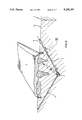
- FIG. 1 is a very small-scale longitudinal section through a dump according to the invention
- FIG. 2 is a larger scale cross section through the dump
- FIG. 3 is a larger view of the detail indicated at III in FIG. 2;
- FIG. 4 is a section taken along line IV--IV of FIG. 3;
- FIG. 5 is a view like FIG. 4 of an alternative arrangement in accordance with this invention.
- FIG. 5A is a large-scale top view of a detail of FIG. 5;
- FIGS. 6 and 7 are small-scale views indicating the system of FIG. 5 in two different operational positions.
- FIG. 8 is a small-scale top view of another system according to the invention.
- a dump 1 here lying mainly above the surface G of the ground is isolated according to this invention by first driving a tunnel 2 longitudinally underneath it.
- the tunnel 2 has a middle portion that extends horizontally and two end portions 10 that open at the surface G and that may run at an incline as shown or vertically as shafts.
- Extending upward from each side of the tunnel according to the invention is a slit 3 whose lower end opens into the tunnel 2 and whose upper end 4 opens at the surface G. These slits 3 are cut right from the surface so that they form with the tunnel 2 a boat-shaped cut underneath the dump 1.
- the slits 3 are made by a longwall mining machine comprising a face cutter 5 having rotary heads 17, a conveyor 6, a roof-prop system 7, and a device 8 for conveying stowing material 9 into the cut 3 behind the machine.
- the conveyor 6 displaces rock and other material cut from the transverse face down to the tunnel 2 whence it is moved by another standard conveyor up to one of its ends. This material and/or other material is then fed back down from the slit end 4 to the device 8 for stowing behind the machine to prevent cave-ins.
- the conveyor 6 has a trough 11 whose outlet end empties onto another such conveyor in the tunnel 2.
- a spool 23 of a vapor-barrier foil 12, a thick synthetic-resin sheet, is held on the machine and is unwound behind it as it advances longitudinally parallel to the tunnel 2.
- the machine cuts grooves 13 in the ceiling of the cuts 3 and lays perforated drainage pipes 14 in these grooves. These pipes 14 therefore lie atop the liquid-barrier film 12 to allow any leachate to be drawn off, thereby protecting the underlying water table.
- the stowing material 9 is typically also mixed with a waterproofing material, for instance clay and/or portland cement, so that it forms yet another liquid barrier.
- the prop 7 includes a front prop 18 and a rear prop 19, each comprising a floor-engaging element 15, a ceiling engaging element 16, and hydraulic rams 24 that press the ceiling element 16 up and floor elements 15 down, thereby preventing caveins behind the cutter 5.
- Transversely extending rams 22 between the front and rear props 18 and 19 allow them to be stepped along behind the advancing machine as can be seen by a comparison of FIGS. 6 and 7.
- the two roof elements 16 are comb-shaped and interfit as shown at 25 in FIG. 5A.
- the rear prop 19 carries a vertical shield 20 behind which the stowing material 9 is packed. This stowing material 9 is fed to the back of the cut via a pipe 21 from the rear conveyor 8.
- the props 18 and 19 are articulated together about axes running parallel to the tunnel 2 so they can follow any irregularities in the cut.
- FIG. 8 shows another arrangement wherein the machine 5' has a helix cutter 26 followed by a prop 27 and a conveyor 28. Cables 29 or the like pass through previously drilled holes to pull the machine along. Once again the stowing material is fed from the back end of the slit to the rear of the face.
Abstract
A dump sitting on the ground is isolated by first driving a tunnel longitudinally through the ground underneath the dump, then cutting from at least one side of the tunnel with a longwall-mining machine a longitudinally and transversely extending slit having a lower end opening into the tunnel and an upper end opening at ground level, and providing a liquid barrier in the slit underneath the dump. The material dug by the machine to form the slit is first conveyed downward along the slit into the tunnel and thence along and out of the tunnel. Stowing material is brought into the slit from the upper end thereof to backfill behind the machine. The cutting machine itself can be a standard cutter head with a longwall conveyor and a set of following props that hold up the roof behind the cutter until this area is backfilled.
Description
The present invention relates to the protection of the ground water underneath a dump. More particularly this invention concerns a method of and apparatus for isolating a ground-level dump to protect the underlying water table.
In order to prevent toxic materials in a ground-level or above-ground dump from leaching into the water table underneath the dump, it is known to install under the dump a leach field from which liquids can be drawn, to prevent them from working themselves deeper into the water table. Such a system does not provide a high degree of protection, as liquid can leak past the leach-field pipes. Furthermore such pipes must normally be installed before the dump is made, that is they cannot be installed readily under an existing dump.
It is also known, for example from German patent document 3,617,956 filed May 28, 1986 by Hans Richter to isolate an existing dump by driving under it a succession of tunnels. As each tunnel is driven, a liquid-stopping membrane and/or drainage pipes are installed. The area behind the driving machine is filled with stowing material derived from the face cutter of the machine to prevent caveins, and any excess such material, which may be stone, earth, or clay depending on the ground composition, is conveyed to the surface. Such a procedure is extremely complex an expensive.
In another known system two slit tunnels are driven directly under the dump by longwall-mining techniques. This forms a basically horizontal barrier directly underneath the dump that can be provided with a vapor barrier and/or a drainage system. Horizontally lateral leaching of pollutants in the dump can still take place, unless expensive vertical slit shafts are subsequently cut to join with the outer edges of the horizontal slit and thereby fully isolate the dump.
It is therefore an object of the present invention to provide an improved method of and apparatus for isolating a surface dump.
Another object is the provision of such an improved method of and apparatus for isolating a surface dump which over come the above-given disadvantages, that is which is relatively simple yet which provides a high degree of protection and isolation underneath the dump.
A method of isolating a dump sitting on the ground according to this invention entails first driving a tunnel longitudinally through the ground underneath the dump, then cutting from at least one side of the tunnel with a longwall-mining machine a longitudinally and transversely extending slit having a lower end opening into the tunnel and an upper end opening at ground level, and providing a liquid barrier in the slit underneath the dump. According to the invention the material dug by the machine to form the slit is first conveyed downward along the slit into the tunnel and thence along and out of the tunnel. Stowing material is brought into the slit from the upper end thereof to backfill behind the machine.
This procedure is fairly simple, and allows the dump to be effectively isolated from underneath. A standard longwall-mining machine of the type used to recover a seam of coal can be used to cut the slit. The cutting machine itself can be a standard cutter head with a longwall conveyor and a set of following props that hold up the roof behind the cutter until this area is backfilled. Since at all times there remains a path open to the surface, the various hydraulic and electric power lines can be serviced from surface supplies, further simplifying the system. The spoil is carried off via the tunnel which can be tipped slightly to facilitate collecting any water running into it from the cut.
In accordance with this invention the tunnel has end tunnel portions that extend at an acute angle to the horizontal and open at the surface and is formed between the end portions with a generally horizontal middle portion. These end portions can be vertical shafts, but normally are simply inclined portions. Furthermore one such slit is cut from each side of the tunnel, although in some situations a single such slit might serve to adequately isolate the dump. Two slits form an encapsulation that has the shape of a boat hull, allowing the bulk of the work to be done with standard longwall-mining equipment.
According to further features of the invention the machine is advanced transversely of the tunnel. In addition the roof of the slit is propped up by standard mine props while the face is cut. Furthermore the method can comprise the step of cutting grooves into a roof of the slit and then fitting drainage pipes into these grooves before backfilling the cut. Furthermore the liquid barrier according to this invention is a liquid-stopping sheet installed in the cut behind the cutting machine before backfilling the slit. When a helical-tooth cutter is used holes are bored underneath the dump from the tunnel and draft elements are connected through the holes with the machine to pull same transversely as it cuts the slit.
The apparatus according to this invention has props immediately behind the cutter for supporting a roof of the slit. These props include back props and front props between the back props and the cutter. The cutter, back props, and front props are articulated together about longitudinal axes and are provided with actuators for stepping themselves transversely and relative to each other. Each prop includes an upper roof-engaging part, a lower floor-engaging part, and a vertically extensible actuator braced vertically between the respective parts. The roof parts of the front and back props have interengaging comblike back and front edges. Furthermore the means for providing the liquid barrier includes a supply of a liquid-stopping sheet and means for installing it transversely behind the cutter and above the backfill. It is also within the scope of this invention to employ props that are left in the cut, the backfill filling around them.
The above and other objects, features, and advantages will become more readily apparent from the following, reference being made to the accompanying drawing in which:
FIG. 1 is a very small-scale longitudinal section through a dump according to the invention;
FIG. 2 is a larger scale cross section through the dump;
FIG. 3 is a larger view of the detail indicated at III in FIG. 2;
FIG. 4 is a section taken along line IV--IV of FIG. 3;
FIG. 5 is a view like FIG. 4 of an alternative arrangement in accordance with this invention;
FIG. 5A is a large-scale top view of a detail of FIG. 5;
FIGS. 6 and 7 are small-scale views indicating the system of FIG. 5 in two different operational positions; and
FIG. 8 is a small-scale top view of another system according to the invention.
As seen in FIGS. 1 and 2 a dump 1 here lying mainly above the surface G of the ground is isolated according to this invention by first driving a tunnel 2 longitudinally underneath it. The tunnel 2 has a middle portion that extends horizontally and two end portions 10 that open at the surface G and that may run at an incline as shown or vertically as shafts. Extending upward from each side of the tunnel according to the invention is a slit 3 whose lower end opens into the tunnel 2 and whose upper end 4 opens at the surface G. These slits 3 are cut right from the surface so that they form with the tunnel 2 a boat-shaped cut underneath the dump 1.
As seen in FIGS. 3 and 4 the slits 3 are made by a longwall mining machine comprising a face cutter 5 having rotary heads 17, a conveyor 6, a roof-prop system 7, and a device 8 for conveying stowing material 9 into the cut 3 behind the machine. The conveyor 6 displaces rock and other material cut from the transverse face down to the tunnel 2 whence it is moved by another standard conveyor up to one of its ends. This material and/or other material is then fed back down from the slit end 4 to the device 8 for stowing behind the machine to prevent cave-ins.
As better shown in FIGS. 3 and 4 the conveyor 6 has a trough 11 whose outlet end empties onto another such conveyor in the tunnel 2. A spool 23 of a vapor-barrier foil 12, a thick synthetic-resin sheet, is held on the machine and is unwound behind it as it advances longitudinally parallel to the tunnel 2. In addition the machine cuts grooves 13 in the ceiling of the cuts 3 and lays perforated drainage pipes 14 in these grooves. These pipes 14 therefore lie atop the liquid-barrier film 12 to allow any leachate to be drawn off, thereby protecting the underlying water table. The stowing material 9 is typically also mixed with a waterproofing material, for instance clay and/or portland cement, so that it forms yet another liquid barrier.
The prop 7 includes a front prop 18 and a rear prop 19, each comprising a floor-engaging element 15, a ceiling engaging element 16, and hydraulic rams 24 that press the ceiling element 16 up and floor elements 15 down, thereby preventing caveins behind the cutter 5. Transversely extending rams 22 between the front and rear props 18 and 19 allow them to be stepped along behind the advancing machine as can be seen by a comparison of FIGS. 6 and 7. The two roof elements 16 are comb-shaped and interfit as shown at 25 in FIG. 5A. The rear prop 19 carries a vertical shield 20 behind which the stowing material 9 is packed. This stowing material 9 is fed to the back of the cut via a pipe 21 from the rear conveyor 8. The props 18 and 19 are articulated together about axes running parallel to the tunnel 2 so they can follow any irregularities in the cut.
FIG. 8 shows another arrangement wherein the machine 5' has a helix cutter 26 followed by a prop 27 and a conveyor 28. Cables 29 or the like pass through previously drilled holes to pull the machine along. Once again the stowing material is fed from the back end of the slit to the rear of the face.
Claims (15)
1. A method of isolating a dump sitting on the ground, the method comprising the steps of:
driving a tunnel longitudinally through the ground underneath the dump;
cutting from at least one side of the tunnel with a longwall-mining machine a longitudinally and transversely extending slit having a lower end opening into the tunnel and an upper end opening at ground level;
providing a liquid barrier in the slit underneath the dump;
conveying the material dug by the machine to form the slit downward along the slit into the tunnel and thence along and out of the tunnel; and
bringing stowing material into the slit from the upper end thereof and backfilling behind the machine with the stowing material.
2. The dump-isolation method defined in claim 1 wherein the tunnel has end tunnel portions that extend at an acute angle to the horizontal and open at the surface and is formed between the end portions with a generally horizontal middle portion.
3. The dump-isolation method defined in claim 1 wherein one such slit is cut from each side of the tunnel.
4. The dump-isolation method defined in claim 1 wherein the machine is advanced transversely of the tunnel.
5. The dump-isolation method defined in claim 1, further comprising the step of
propping up a roof of the slit while cutting same.
6. The dump-isolation method defined in claim 1 wherein the liquid barrier is provided by
installing drainage pipes into a roof of the cut before backfilling same.
7. The dump-isolation method defined in claim 1 wherein the liquid barrier is provided by
installing a liquid-stopping sheet in the cut behind the cutting machine before backfilling the slit.
8. The dump-isolation method defined in claim 1, further comprising the steps of
boring holes transversely of and opening into the tunnel; and
connecting draft elements through the holes with the machine to pull same transversely as it cuts the slit.
9. An apparatus for isolating a dump sitting on the ground, the apparatus comprising:
means for driving a tunnel longitudinally through the ground underneath the dump;
means for cutting from at least one side of the tunnel with a longwall-mining machine a longitudinally and transversely extending slit having a lower end opening into the tunnel and an upper end opening at ground level;
means for providing a liquid barrier in the slit underneath the dump;
means for conveying the material dug by the machine to form the slit downward along the slit into the tunnel and thence along and out of the tunnel; and
means for bringing stowing material into the slit from the upper end thereof and backfilling behind the machine with the stowing material.
10. The dump-isolating apparatus defined in claim 9, further comprising
props immediately behind the cutting means for supporting a roof of the slit.
11. The dump-isolating apparatus defined in claim 10 wherein the props include back props and front props between the back props and the cutting means, the cutting means, back props, and front props being articulated together about longitudinal axes and being provided with means for stepping themselves transversely and relative to each other.
12. The dump-isolating apparatus defined in claim 11 wherein each prop includes an upper roof-engaging part, a lower floor-engaging part, and a vertically extensible actuator braced vertically between the respective parts.
13. The dump-isolating apparatus defined in claim 11 wherein the roof parts of the front and back props have interengaging comblike back and front edges.
14. The dump-isolating apparatus defined in claim 9 wherein the means for providing the liquid barrier includes a supply of a liquid-stopping sheet and means for installing it transversely behind the cutting means and above the backfill.
15. A method of isolating a dump sitting on the ground, the method comprising the steps of:
driving a tunnel longitudinally through the ground underneath the dump;
cutting from at least one side of the tunnel with a longwall-mining machine a longitudinally and transversely extending slit having a lower end opening into the tunnel and an upper end opening at ground level;
forming longitudinal grooves in the roof of the slit while cutting same;
providing a liquid barrier in the slit underneath the dump by installing perforated drainage pipes in the grooves;
conveying the material dug by the machine to form the slit downward along the slit into the tunnel and thence along and out of the tunnel; and
bringing stowing material into the slit from the upper end thereof and backfilling behind the machine with the stowing material.
Applications Claiming Priority (4)
| Application Number | Priority Date | Filing Date | Title |
|---|---|---|---|
| DE4018822 | 1990-06-12 | ||
| DE4018824 | 1990-06-12 | ||
| DE19904018822 DE4018822A1 (en) | 1990-06-12 | 1990-06-12 | Securing refuse dump by underground sealing structure |
| DE19904018824 DE4018824C2 (en) | 1990-06-12 | 1990-06-12 | Machine arrangement for the production of a sealing structure in the rock below a landfill |
Publications (1)
| Publication Number | Publication Date |
|---|---|
| US5180251A true US5180251A (en) | 1993-01-19 |
Family
ID=25894077
Family Applications (1)
| Application Number | Title | Priority Date | Filing Date |
|---|---|---|---|
| US07/714,250 Expired - Fee Related US5180251A (en) | 1990-06-12 | 1991-06-11 | Underground protection underneath a dump |
Country Status (5)
| Country | Link |
|---|---|
| US (1) | US5180251A (en) |
| EP (1) | EP0461471A3 (en) |
| JP (1) | JPH04227094A (en) |
| CA (1) | CA2044325A1 (en) |
| RU (1) | RU2015087C1 (en) |
Cited By (13)
| Publication number | Priority date | Publication date | Assignee | Title |
|---|---|---|---|---|
| US5340238A (en) * | 1992-08-04 | 1994-08-23 | Tanknology Corporation International | Method and apparatus for testing above ground liquid storage tanks for leaks |
| US5890840A (en) * | 1995-12-08 | 1999-04-06 | Carter, Jr.; Ernest E. | In situ construction of containment vault under a radioactive or hazardous waste site |
| WO2001040583A1 (en) * | 1999-12-06 | 2001-06-07 | Bechtel Bwxt Idaho, Llc | Advanced containment system |
| US20030152427A1 (en) * | 2000-12-04 | 2003-08-14 | Nickelson Reva A. | In situ retreival of contaminants or other substances using a barrier system and leaching solutions and components, processes and methods relating thereto |
| US6758634B2 (en) | 2001-02-06 | 2004-07-06 | Bechtel Bwxt Idaho, Llc | Subsurface materials management and containment system |
| US20040218980A1 (en) * | 2000-12-04 | 2004-11-04 | Richardson John G. | Apparatus for indication of at least one subsurface barrier characteristic and methods of use |
| US20050063784A1 (en) * | 2000-12-04 | 2005-03-24 | Bechtel Bwxt Idaho, Llc | Barriers including at least one weld, barriers including at least one adhesive joint, methods and apparatuses for forming, inspecting, selectively heating, and repairing same |
| US20050207846A1 (en) * | 2000-12-04 | 2005-09-22 | Nickelson Reva A | Method of in situ retrieval of contaminants or other substances using a barrier system and leaching solutions |
| US20050257959A1 (en) * | 2004-05-20 | 2005-11-24 | Richardson John G | Microtunneling systems and methods of use |
| US7976243B2 (en) | 2006-06-15 | 2011-07-12 | Green Core Technologies, Llc | Methods and apparatus for installing conduit underground |
| US8596916B2 (en) | 2006-06-15 | 2013-12-03 | Joseph M Rohde | Apparatus for installing conduit underground |
| WO2018164593A1 (en) * | 2017-03-07 | 2018-09-13 | Maciej Bargiel Tnk Projekt | Device for trenchless forming of concrete partitions in the ground, in particular heat accumulating tanks |
| CN113585307A (en) * | 2021-09-02 | 2021-11-02 | 曹双利 | Water conservancy project impermeable membrane cofferdam structure and construction method thereof |
Families Citing this family (1)
| Publication number | Priority date | Publication date | Assignee | Title |
|---|---|---|---|---|
| CN113882861B (en) * | 2021-11-04 | 2023-06-23 | 攀钢集团矿业有限公司 | Method for recovering hanging ore on leaning step in surface mine |
Citations (12)
| Publication number | Priority date | Publication date | Assignee | Title |
|---|---|---|---|---|
| US4439062A (en) * | 1981-12-21 | 1984-03-27 | American Colloid Co. | Sealing system and method for sealing earthen containers |
| DE3409591A1 (en) * | 1984-03-15 | 1985-09-19 | Dyckerhoff & Widmann AG, 8000 München | Method and apparatus for producing an underground sealing base |
| WO1986007107A1 (en) * | 1985-05-28 | 1986-12-04 | Hans Richter | Method and device for post-setting a liquid impervious layer in extended dumping grounds and contaminated areas in order to protect ground waters |
| US4634187A (en) * | 1984-11-21 | 1987-01-06 | Isl Ventures, Inc. | Method of in-situ leaching of ores |
| EP0235353A2 (en) * | 1986-03-07 | 1987-09-09 | Niederberg-Chemie GmbH | Breakage protection for a trench shield |
| US4753551A (en) * | 1985-02-19 | 1988-06-28 | Basf Aktiengesellschaft | Sealing screen for waste dumps |
| US4846604A (en) * | 1987-03-04 | 1989-07-11 | Heers & Brockstedt, Gmbh & Co. | Dump formation and method of monitoring and repairing leakages in dumps |
| US4904112A (en) * | 1989-07-26 | 1990-02-27 | Mcdonald Carroll W | Underground irrigation system |
| US4973196A (en) * | 1988-12-15 | 1990-11-27 | Bayer Aktiengesellschaft | Process for the intermediate sealing of dumps |
| US5043076A (en) * | 1989-08-11 | 1991-08-27 | American Colloid Company | In situ treatment of waste water to prevent ground water contamination |
| US5078543A (en) * | 1990-07-11 | 1992-01-07 | Terrel Ronald L | Storage system for solid waste material |
| US5080528A (en) * | 1981-04-09 | 1992-01-14 | Finic, B.V. | Method and apparatus for impounding fluids |
Family Cites Families (6)
| Publication number | Priority date | Publication date | Assignee | Title |
|---|---|---|---|---|
| DE2806982C2 (en) * | 1978-02-18 | 1986-08-14 | Gewerkschaft Eisenhütte Westfalia GmbH, 4670 Lünen | Striding extension for blow molding plants in inclined storage |
| DE3424981A1 (en) * | 1984-07-06 | 1986-01-16 | Ingenieurbüro Eber & Partner, 8000 München | Method of sealing off the bases of extensive landfills from ground water |
| DE3573629D1 (en) * | 1985-05-10 | 1989-11-16 | Niederberg Chemie | Ulterior sealing of waste tips and contaminated surfaces |
| DE3530469A1 (en) * | 1985-08-27 | 1987-03-05 | Niederberg Chemie | Nocturnal landfill seals with mining mining |
| EP0230667B1 (en) * | 1985-12-27 | 1991-07-24 | Alfred Kunz GmbH & Co. | Method for the stripe-wise removal of subsoil layers, especially non-rigid ones |
| DE3677010D1 (en) * | 1986-05-27 | 1991-02-21 | Dyckerhoff & Widmann Ag | METHOD AND DEVICE FOR THE INSTALLATION OF CONSTRUCTION ELEMENTS ON A WIDE BASE IN THE GROUND FLOOR IN THE UNDERGROUND CONSTRUCTION. |
-
1991
- 1991-05-29 EP EP19910108761 patent/EP0461471A3/en not_active Ceased
- 1991-06-11 CA CA002044325A patent/CA2044325A1/en not_active Abandoned
- 1991-06-11 RU SU914895640A patent/RU2015087C1/en active
- 1991-06-11 US US07/714,250 patent/US5180251A/en not_active Expired - Fee Related
- 1991-06-12 JP JP3140385A patent/JPH04227094A/en active Pending
Patent Citations (13)
| Publication number | Priority date | Publication date | Assignee | Title |
|---|---|---|---|---|
| US5080528A (en) * | 1981-04-09 | 1992-01-14 | Finic, B.V. | Method and apparatus for impounding fluids |
| US4439062A (en) * | 1981-12-21 | 1984-03-27 | American Colloid Co. | Sealing system and method for sealing earthen containers |
| DE3409591A1 (en) * | 1984-03-15 | 1985-09-19 | Dyckerhoff & Widmann AG, 8000 München | Method and apparatus for producing an underground sealing base |
| US4634187A (en) * | 1984-11-21 | 1987-01-06 | Isl Ventures, Inc. | Method of in-situ leaching of ores |
| US4753551A (en) * | 1985-02-19 | 1988-06-28 | Basf Aktiengesellschaft | Sealing screen for waste dumps |
| DE3617956A1 (en) * | 1985-05-28 | 1987-12-03 | Hans Richter | METHOD AND DEVICE FOR THE INNOVATIVE PUTTING IN OF A LIQUID-IMPERPERABLE LAYER IN EXPANDED LANDFILLS AND CONTAMINATED LOCATIONS FOR PROTECTING THE GROUNDWATER |
| WO1986007107A1 (en) * | 1985-05-28 | 1986-12-04 | Hans Richter | Method and device for post-setting a liquid impervious layer in extended dumping grounds and contaminated areas in order to protect ground waters |
| EP0235353A2 (en) * | 1986-03-07 | 1987-09-09 | Niederberg-Chemie GmbH | Breakage protection for a trench shield |
| US4846604A (en) * | 1987-03-04 | 1989-07-11 | Heers & Brockstedt, Gmbh & Co. | Dump formation and method of monitoring and repairing leakages in dumps |
| US4973196A (en) * | 1988-12-15 | 1990-11-27 | Bayer Aktiengesellschaft | Process for the intermediate sealing of dumps |
| US4904112A (en) * | 1989-07-26 | 1990-02-27 | Mcdonald Carroll W | Underground irrigation system |
| US5043076A (en) * | 1989-08-11 | 1991-08-27 | American Colloid Company | In situ treatment of waste water to prevent ground water contamination |
| US5078543A (en) * | 1990-07-11 | 1992-01-07 | Terrel Ronald L | Storage system for solid waste material |
Cited By (39)
| Publication number | Priority date | Publication date | Assignee | Title |
|---|---|---|---|---|
| US5340238A (en) * | 1992-08-04 | 1994-08-23 | Tanknology Corporation International | Method and apparatus for testing above ground liquid storage tanks for leaks |
| US5890840A (en) * | 1995-12-08 | 1999-04-06 | Carter, Jr.; Ernest E. | In situ construction of containment vault under a radioactive or hazardous waste site |
| US6280521B1 (en) | 1995-12-08 | 2001-08-28 | Carter Ernest E Jr | Grout compositions for construction of subterranean barriers |
| US6569235B2 (en) | 1995-12-08 | 2003-05-27 | Ernest E. Carter, Jr. | Grout compositions for construction of subterranean barriers |
| US6860936B2 (en) | 1995-12-08 | 2005-03-01 | Ernest E. Carter, Jr. | Grout compositions for construction of subterranean barriers |
| EP1015141A1 (en) | 1996-12-06 | 2000-07-05 | Ernest E. Carter, Jr. | In situ construction of containment vault under a radioactive or hazardous waste site |
| US6851890B2 (en) | 1999-12-06 | 2005-02-08 | Bechtel Bwxt Idaho, Llc | Advanced containment system |
| WO2001040583A1 (en) * | 1999-12-06 | 2001-06-07 | Bechtel Bwxt Idaho, Llc | Advanced containment system |
| US6575663B2 (en) * | 1999-12-06 | 2003-06-10 | Bechtel Bwxt Idaho, Llc | Advanced containment system |
| US20030198517A1 (en) * | 1999-12-06 | 2003-10-23 | Kostelnik Kevin M. | Advanced containment system |
| US6896446B2 (en) | 1999-12-06 | 2005-05-24 | Bechtel Bwxt Idaho, Llc | Advanced containment system |
| US6802670B2 (en) | 1999-12-06 | 2004-10-12 | Bechtel Bwxt Idaho, Llc | Advanced containment system |
| US20060239778A1 (en) * | 2000-12-04 | 2006-10-26 | Nickelson Reva A | Method of sealing casings of subsurface materials management system |
| US20060093437A1 (en) * | 2000-12-04 | 2006-05-04 | Nickelson Reva A | Subsurface materials management and containment system |
| US20040191002A1 (en) * | 2000-12-04 | 2004-09-30 | Nickelson Reva A. | Subsurface materials management and containment system, components thereof and methods relating thereto |
| US20050063784A1 (en) * | 2000-12-04 | 2005-03-24 | Bechtel Bwxt Idaho, Llc | Barriers including at least one weld, barriers including at least one adhesive joint, methods and apparatuses for forming, inspecting, selectively heating, and repairing same |
| US7513715B2 (en) | 2000-12-04 | 2009-04-07 | Battelle Energy Alliance, Llc | Subterranean barriers, methods, and apparatuses for forming, inspecting, selectively heating, and repairing same |
| US6910829B2 (en) | 2000-12-04 | 2005-06-28 | Battelle Energy Alliance, Llc | In situ retreival of contaminants or other substances using a barrier system and leaching solutions and components, processes and methods relating thereto |
| US20050207846A1 (en) * | 2000-12-04 | 2005-09-22 | Nickelson Reva A | Method of in situ retrieval of contaminants or other substances using a barrier system and leaching solutions |
| US7278800B2 (en) | 2000-12-04 | 2007-10-09 | Battelle Energy Alliance, Llc | Method of installing subsurface barrier |
| US7029203B2 (en) | 2000-12-04 | 2006-04-18 | Battelle Energy Alliance, Llc | Subsurface materials management and containment system, components thereof and methods relating thereto |
| US7172371B2 (en) | 2000-12-04 | 2007-02-06 | Battelle Energy Alliance, Llc | Method of sealing casings of subsurface materials management system |
| US20060099036A1 (en) * | 2000-12-04 | 2006-05-11 | Nickelson Reva A | Method of installing subsurface barrier |
| US7056063B2 (en) | 2000-12-04 | 2006-06-06 | Battelle Energy Alliance, Llc | Apparatus for indication of at least one subsurface barrier characteristic |
| US20070209798A1 (en) * | 2000-12-04 | 2007-09-13 | Battelle Energy Alliance, Llc | Subterranean barriers, methods, and apparatuses for forming, inspsecting, selectively heating, and repairing same |
| US20040218980A1 (en) * | 2000-12-04 | 2004-11-04 | Richardson John G. | Apparatus for indication of at least one subsurface barrier characteristic and methods of use |
| US7121765B2 (en) | 2000-12-04 | 2006-10-17 | Battelle Energy Alliance, Llc | Subsurface materials management and containment system |
| US20030152427A1 (en) * | 2000-12-04 | 2003-08-14 | Nickelson Reva A. | In situ retreival of contaminants or other substances using a barrier system and leaching solutions and components, processes and methods relating thereto |
| US7153061B2 (en) | 2000-12-04 | 2006-12-26 | Battelle Energy Alliance, Llc | Method of in situ retrieval of contaminants or other substances using a barrier system and leaching solutions |
| US7160061B2 (en) | 2000-12-04 | 2007-01-09 | Battelle Energy Alliance, Llc | Subterranean barriers including at least one weld |
| US7234895B2 (en) | 2001-02-06 | 2007-06-26 | Battelle Energy Alliance, Llc | Methods for indication of at least one subsurface barrier characteristic and methods of use |
| US20060182499A1 (en) * | 2001-02-06 | 2006-08-17 | Richardson John G | Methods for indication of at least one subsurface barrier characteristic and methods of use |
| US6758634B2 (en) | 2001-02-06 | 2004-07-06 | Bechtel Bwxt Idaho, Llc | Subsurface materials management and containment system |
| US7070359B2 (en) | 2004-05-20 | 2006-07-04 | Battelle Energy Alliance, Llc | Microtunneling systems and methods of use |
| US20050257959A1 (en) * | 2004-05-20 | 2005-11-24 | Richardson John G | Microtunneling systems and methods of use |
| US7976243B2 (en) | 2006-06-15 | 2011-07-12 | Green Core Technologies, Llc | Methods and apparatus for installing conduit underground |
| US8596916B2 (en) | 2006-06-15 | 2013-12-03 | Joseph M Rohde | Apparatus for installing conduit underground |
| WO2018164593A1 (en) * | 2017-03-07 | 2018-09-13 | Maciej Bargiel Tnk Projekt | Device for trenchless forming of concrete partitions in the ground, in particular heat accumulating tanks |
| CN113585307A (en) * | 2021-09-02 | 2021-11-02 | 曹双利 | Water conservancy project impermeable membrane cofferdam structure and construction method thereof |
Also Published As
| Publication number | Publication date |
|---|---|
| EP0461471A2 (en) | 1991-12-18 |
| EP0461471A3 (en) | 1992-04-08 |
| JPH04227094A (en) | 1992-08-17 |
| CA2044325A1 (en) | 1991-12-13 |
| RU2015087C1 (en) | 1994-06-30 |
Similar Documents
| Publication | Publication Date | Title |
|---|---|---|
| US5180251A (en) | Underground protection underneath a dump | |
| US5199816A (en) | System for isolating a dump | |
| US11008860B2 (en) | Equipment system for no-roadway no-coal-pillar retained roadway mining method | |
| US5816750A (en) | Automatic grid layout system | |
| US5685668A (en) | Barrier wall installation system | |
| US3994139A (en) | Apparatus for and a method of laying a pipe line | |
| RU2344291C2 (en) | System of deposit development | |
| US4017122A (en) | Longwall trench mining system | |
| US3999804A (en) | Longwall mining with chain pillar recovery | |
| US4726712A (en) | Method of pipeline filling the interstices of controlled caving areas | |
| CN108397195B (en) | Steep-inclined thick coal seam mechanical coal mining system and coal-mining method | |
| US3708984A (en) | Tunnel liner jacking system and method | |
| GB2224053A (en) | Mining method | |
| DE3607499A1 (en) | Method of sealing the soil surface area of an old or operating landfill site in a gastight and watertight manner | |
| US3695714A (en) | Mining ventilation method | |
| CA2289269C (en) | Softwall mining method and device | |
| US4900191A (en) | Method for removal of broken ground | |
| EP0482405B1 (en) | Method for secondary construction of an underground sealing-base under a consisting dump | |
| RU2151294C1 (en) | Method of horizontal slicing of thick steep coal seam | |
| RU2013549C1 (en) | Method for artificial interhorizontal pillar building by mining steep and inclined formations | |
| SU1710751A1 (en) | Method of mining thick steeply dipping seams with filling | |
| SU1710750A1 (en) | Method of mining thick coal seams with filling | |
| Klados | Experiences with hard rock shielded TBMs in special conditions | |
| JP2641618B2 (en) | Pilot tunnel construction method | |
| EP0230667A2 (en) | Method for the stripe-wise removal of subsoil layers, especially non-rigid ones |
Legal Events
| Date | Code | Title | Description |
|---|---|---|---|
| REMI | Maintenance fee reminder mailed | ||
| LAPS | Lapse for failure to pay maintenance fees | ||
| FP | Lapsed due to failure to pay maintenance fee |
Effective date: 19970122 |
|
| STCH | Information on status: patent discontinuation |
Free format text: PATENT EXPIRED DUE TO NONPAYMENT OF MAINTENANCE FEES UNDER 37 CFR 1.362 |