US5201011A - Method and apparatus for image hand markup detection using morphological techniques - Google Patents
Method and apparatus for image hand markup detection using morphological techniques Download PDFInfo
- Publication number
- US5201011A US5201011A US07/794,275 US79427591A US5201011A US 5201011 A US5201011 A US 5201011A US 79427591 A US79427591 A US 79427591A US 5201011 A US5201011 A US 5201011A
- Authority
- US
- United States
- Prior art keywords
- image
- document image
- hand
- document
- regions
- Prior art date
- Legal status (The legal status is an assumption and is not a legal conclusion. Google has not performed a legal analysis and makes no representation as to the accuracy of the status listed.)
- Expired - Lifetime
Links
- 238000000034 method Methods 0.000 title claims abstract description 88
- 230000000877 morphologic effect Effects 0.000 title claims abstract description 30
- 238000001514 detection method Methods 0.000 title abstract description 41
- 238000012545 processing Methods 0.000 claims abstract description 23
- 230000010339 dilation Effects 0.000 claims description 18
- 239000007787 solid Substances 0.000 claims description 17
- 238000000605 extraction Methods 0.000 claims description 14
- 238000012360 testing method Methods 0.000 claims description 10
- 230000000916 dilatatory effect Effects 0.000 claims description 4
- 230000003247 decreasing effect Effects 0.000 claims 2
- 239000000284 extract Substances 0.000 abstract description 7
- 238000013213 extrapolation Methods 0.000 abstract 1
- 238000013459 approach Methods 0.000 description 24
- 230000009467 reduction Effects 0.000 description 19
- 230000003628 erosive effect Effects 0.000 description 14
- 230000008569 process Effects 0.000 description 7
- 239000000463 material Substances 0.000 description 5
- 238000012015 optical character recognition Methods 0.000 description 3
- 230000008859 change Effects 0.000 description 2
- 230000000694 effects Effects 0.000 description 2
- 239000003550 marker Substances 0.000 description 2
- 230000000873 masking effect Effects 0.000 description 2
- 230000003287 optical effect Effects 0.000 description 2
- 239000000523 sample Substances 0.000 description 2
- 238000000926 separation method Methods 0.000 description 2
- 101001022148 Homo sapiens Furin Proteins 0.000 description 1
- 101000701936 Homo sapiens Signal peptidase complex subunit 1 Proteins 0.000 description 1
- 102100030313 Signal peptidase complex subunit 1 Human genes 0.000 description 1
- 230000009471 action Effects 0.000 description 1
- 239000011449 brick Substances 0.000 description 1
- 238000004422 calculation algorithm Methods 0.000 description 1
- 239000002131 composite material Substances 0.000 description 1
- 238000007796 conventional method Methods 0.000 description 1
- 238000013461 design Methods 0.000 description 1
- 238000010586 diagram Methods 0.000 description 1
- 230000003993 interaction Effects 0.000 description 1
- 230000001788 irregular Effects 0.000 description 1
- 238000002372 labelling Methods 0.000 description 1
- 238000013507 mapping Methods 0.000 description 1
- 238000005259 measurement Methods 0.000 description 1
- 238000012986 modification Methods 0.000 description 1
- 230000004048 modification Effects 0.000 description 1
- 238000002310 reflectometry Methods 0.000 description 1
- 230000011218 segmentation Effects 0.000 description 1
- 230000001131 transforming effect Effects 0.000 description 1
- 238000009966 trimming Methods 0.000 description 1
Images


Classifications
-
- G—PHYSICS
- G06—COMPUTING; CALCULATING OR COUNTING
- G06T—IMAGE DATA PROCESSING OR GENERATION, IN GENERAL
- G06T7/00—Image analysis
- G06T7/70—Determining position or orientation of objects or cameras
-
- G—PHYSICS
- G06—COMPUTING; CALCULATING OR COUNTING
- G06V—IMAGE OR VIDEO RECOGNITION OR UNDERSTANDING
- G06V30/00—Character recognition; Recognising digital ink; Document-oriented image-based pattern recognition
- G06V30/10—Character recognition
- G06V30/14—Image acquisition
- G06V30/1444—Selective acquisition, locating or processing of specific regions, e.g. highlighted text, fiducial marks or predetermined fields
- G06V30/1448—Selective acquisition, locating or processing of specific regions, e.g. highlighted text, fiducial marks or predetermined fields based on markings or identifiers characterising the document or the area
-
- G—PHYSICS
- G06—COMPUTING; CALCULATING OR COUNTING
- G06V—IMAGE OR VIDEO RECOGNITION OR UNDERSTANDING
- G06V30/00—Character recognition; Recognising digital ink; Document-oriented image-based pattern recognition
- G06V30/10—Character recognition
Definitions
- U.S. Pat. No. 5,029,224 to Fujisawa describes a marked region recognition apparatus which recognizes an arbitrary marked region of a document image from a mark signal which indicates whether or not there exists a mark for delineating the marked region.
- the marked region recognition apparatus comprises a first storing part for storing a mark signal for at least one scanning line, a second storing part for storing a coordinate in a main scanning direction where the mark region ends for each scanning line based on the mark signal stored in the first storing part, and a recognition part for recognizing an inside and an outside of the marked region and for producing a marked region signal which indicates the inside or the outside of the marked region for a present scanning line contiguous with the marked region signal of a previous scanning line, where a state of the marked region signal of a previous scanning line is obtained from the first and second storing parts.
- FIG. 6 is an example of a second image formed by of the indirect markup detection method of FIG. 3, the second image resulting from a morphological CLOSING operation of the first image of FIG. 5.
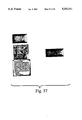
- FIG. 34 is an example of a seventh image of the other preferred embodiment of a direct approach for hand markup detection.
- underlines are typically applied to image units that represent words, so the processing that is intended to lift the material above the underline should be word-oriented. After the image unit is extracted, the pixels representing the underline can be subtracted.
- the image hand mark detection device 80 of FIG. 4 includes, for example, a user input device 82, processor 84, monitor 86, read only memory 88, random access memory 90, files 92 and an output device 94.
- Device 80 represents any number of automatic devices for altering a document image such as a computer system, a facsimile system or a photocopying system.
- the user input device, 82 represents any user input device such as a keyboard, optical scanner electronic scanner, photocopier or facsimile machine.
Abstract
Description
Claims (22)
Priority Applications (4)
| Application Number | Priority Date | Filing Date | Title |
|---|---|---|---|
| US07/794,275 US5201011A (en) | 1991-11-19 | 1991-11-19 | Method and apparatus for image hand markup detection using morphological techniques |
| JP30272092A JP3305772B2 (en) | 1991-11-19 | 1992-11-12 | Method for detecting handwritten instruction image using morphological technique |
| DE69230635T DE69230635T2 (en) | 1991-11-19 | 1992-11-16 | Process and device for image / hand marking determination |
| EP92310438A EP0543599B1 (en) | 1991-11-19 | 1992-11-16 | Method and apparatus for image hand markup detection |
Applications Claiming Priority (1)
| Application Number | Priority Date | Filing Date | Title |
|---|---|---|---|
| US07/794,275 US5201011A (en) | 1991-11-19 | 1991-11-19 | Method and apparatus for image hand markup detection using morphological techniques |
Publications (1)
| Publication Number | Publication Date |
|---|---|
| US5201011A true US5201011A (en) | 1993-04-06 |
Family
ID=25162194
Family Applications (1)
| Application Number | Title | Priority Date | Filing Date |
|---|---|---|---|
| US07/794,275 Expired - Lifetime US5201011A (en) | 1991-11-19 | 1991-11-19 | Method and apparatus for image hand markup detection using morphological techniques |
Country Status (4)
| Country | Link |
|---|---|
| US (1) | US5201011A (en) |
| EP (1) | EP0543599B1 (en) |
| JP (1) | JP3305772B2 (en) |
| DE (1) | DE69230635T2 (en) |
Cited By (54)
| Publication number | Priority date | Publication date | Assignee | Title |
|---|---|---|---|---|
| US5374932A (en) * | 1993-08-02 | 1994-12-20 | Massachusetts Institute Of Technology | Airport surface surveillance system |
| US5438630A (en) * | 1992-12-17 | 1995-08-01 | Xerox Corporation | Word spotting in bitmap images using word bounding boxes and hidden Markov models |
| US5519618A (en) * | 1993-08-02 | 1996-05-21 | Massachusetts Institute Of Technology | Airport surface safety logic |
| US5555556A (en) * | 1994-09-30 | 1996-09-10 | Xerox Corporation | Method and apparatus for document segmentation by background analysis |
| EP0738987A2 (en) * | 1995-04-21 | 1996-10-23 | Xerox Corporation | Processing machine readable forms |
| US5592568A (en) * | 1992-12-17 | 1997-01-07 | Xerox Corporation | Word spotting in bitmap images using context-sensitive character models without baselines |
| WO1997009690A1 (en) * | 1995-09-05 | 1997-03-13 | Northrop Grumman Corporation | Data dimensional sieving and fuzzy connectivity for mri image analysis |
| US5692073A (en) * | 1996-05-03 | 1997-11-25 | Xerox Corporation | Formless forms and paper web using a reference-based mark extraction technique |
| US5729741A (en) * | 1995-04-10 | 1998-03-17 | Golden Enterprises, Inc. | System for storage and retrieval of diverse types of information obtained from different media sources which includes video, audio, and text transcriptions |
| US5745600A (en) * | 1992-12-17 | 1998-04-28 | Xerox Corporation | Word spotting in bitmap images using text line bounding boxes and hidden Markov models |
| US5745610A (en) * | 1993-07-22 | 1998-04-28 | Xerox Corporation | Data access based on human-produced images |
| US5787208A (en) * | 1995-06-07 | 1998-07-28 | Neopath, Inc. | Image enhancement method and apparatus |
| US5813018A (en) * | 1991-11-27 | 1998-09-22 | Hitachi Microcomputer System Ltd. | Automated text extraction from source drawing and composition into target drawing with translated text placement according to source image analysis |
| US5937077A (en) * | 1996-04-25 | 1999-08-10 | General Monitors, Incorporated | Imaging flame detection system |
| US5966136A (en) * | 1995-04-12 | 1999-10-12 | Hewlett-Packard Co. | Efficient method for clipping numerous objects against an arbitrary clipping path |
| US6192160B1 (en) * | 1996-09-19 | 2001-02-20 | Hyundai Microelectronics Co., Ltd. | Hardware architectures for image dilation and erosion operations |
| US6275304B1 (en) * | 1998-12-22 | 2001-08-14 | Xerox Corporation | Automated enhancement of print quality based on feature size, shape, orientation, and color |
| US20010036317A1 (en) * | 2000-04-26 | 2001-11-01 | Toshihiro Mori | Apparatus and method for detecting a pattern |
| US20020001029A1 (en) * | 2000-06-29 | 2002-01-03 | Fuji Xerox Co., Ltd. | Image processing apparatus, image processing method, and storage medium |
| US20020028020A1 (en) * | 2000-09-04 | 2002-03-07 | Yoko Fujiwara | Image processing device, image processing method, and image processing program |
| US6411732B1 (en) * | 1994-09-09 | 2002-06-25 | Xerox Corporation | Method for interpreting hand drawn diagrammatic user interface commands |
| US6415048B1 (en) | 1993-10-12 | 2002-07-02 | Schneider Medical Technologies, Inc. | Compositional analysis system |
| US6597808B1 (en) * | 1999-12-06 | 2003-07-22 | Matsushita Electric Industrial Co., Ltd. | User drawn circled region extraction from scanned documents |
| US20030222230A1 (en) * | 2002-04-09 | 2003-12-04 | Ralf Brauner | Method and apparatus for the capture of scanning positions in printed images |
| US20040120604A1 (en) * | 2002-08-27 | 2004-06-24 | Najman Laurent Alain | Skew detection |
| US6766069B1 (en) * | 1999-12-21 | 2004-07-20 | Xerox Corporation | Text selection from images of documents using auto-completion |
| US6867875B1 (en) | 1999-12-06 | 2005-03-15 | Matsushita Electric Industrial Co., Ltd. | Method and apparatus for simplifying fax transmissions using user-circled region detection |
| US20050063609A1 (en) * | 2003-09-23 | 2005-03-24 | Shih-Hung Chien | Device that appends a recognition point for image joining to the extracted image and a recognition element thereof |
| US20060009955A1 (en) * | 2004-07-07 | 2006-01-12 | Gendron Marlin L | System, method and apparatus for clustering features |
| US20060153449A1 (en) * | 2005-01-11 | 2006-07-13 | Samsung Electronics Co., Ltd. | Block-based parallel image thinning methods, computer program products and systems |
| US20070036432A1 (en) * | 2003-11-12 | 2007-02-15 | Li-Qun Xu | Object detection in images |
| US20070115500A1 (en) * | 2005-11-21 | 2007-05-24 | Xerox Corporation | Method for operating communication device |
| US20080069473A1 (en) * | 2006-09-19 | 2008-03-20 | Yoshiharu Tojo | Image management method and image processing apparatus |
| US20080144131A1 (en) * | 2006-12-14 | 2008-06-19 | Samsung Electronics Co., Ltd. | Image forming apparatus and method of controlling the same |
| US20080212132A1 (en) * | 2007-03-02 | 2008-09-04 | Brother Kogyo Kabushiki Kaisha | Image processing apparatus and printing apparatus |
| US20090251468A1 (en) * | 2008-04-03 | 2009-10-08 | Peled Nachshon | Animating of an input-image to create personal worlds |
| US20090263042A1 (en) * | 2008-04-21 | 2009-10-22 | Dainippon Screen Mfg. Co., Ltd | Line drawing processor, line drawing processing method, and program therefor |
| US7834819B2 (en) | 2004-04-01 | 2010-11-16 | Polyvision Corporation | Virtual flip chart method and apparatus |
| US20110007366A1 (en) * | 2009-07-10 | 2011-01-13 | Palo Alto Research Center Incorporated | System and method for classifying connected groups of foreground pixels in scanned document images according to the type of marking |
| US20110007970A1 (en) * | 2009-07-10 | 2011-01-13 | Palo Alto Research Center Incorporated | System and method for segmenting text lines in documents |
| US20110007964A1 (en) * | 2009-07-10 | 2011-01-13 | Palo Alto Research Center Incorporated | System and method for machine-assisted human labeling of pixels in an image |
| US20110058742A1 (en) * | 2009-09-04 | 2011-03-10 | Carpenter Michael D | System and method for determining authorship of a document |
| US7948448B2 (en) | 2004-04-01 | 2011-05-24 | Polyvision Corporation | Portable presentation system and methods for use therewith |
| US20110154174A1 (en) * | 2009-12-23 | 2011-06-23 | Fuji Xerox Co., Ltd. | Embedded media markers and systems and methods for generating and using them |
| US8009928B1 (en) * | 2008-01-23 | 2011-08-30 | A9.Com, Inc. | Method and system for detecting and recognizing text in images |
| US20120163718A1 (en) * | 2010-12-28 | 2012-06-28 | Prakash Reddy | Removing character from text in non-image form where location of character in image of text falls outside of valid content boundary |
| US8896721B2 (en) | 2009-05-29 | 2014-11-25 | Microsoft Corporation | Environment and/or target segmentation |
| US9031324B2 (en) * | 2013-03-19 | 2015-05-12 | Brother Kogyo Kabushiki Kaisha | Image-processing device specifying encircling line for identifying sub-region of image |
| US9558433B2 (en) | 2015-06-30 | 2017-01-31 | Brother Kogyo Kabushiki Kaisha | Image processing apparatus generating partially erased image data and supplementary data supplementing partially erased image data |
| US10049097B1 (en) * | 2017-01-27 | 2018-08-14 | Xerox Corporation | Systems and methods for creating multi-layered optical character recognition (OCR) documents |
| US10264213B1 (en) | 2016-12-15 | 2019-04-16 | Steelcase Inc. | Content amplification system and method |
| CN111127534A (en) * | 2019-11-05 | 2020-05-08 | 深圳市三宝创新智能有限公司 | Obstacle detection method |
| EP3926526A3 (en) * | 2020-06-16 | 2022-02-16 | Beijing Baidu Netcom Science And Technology Co., Ltd. | Optical character recognition method and apparatus, electronic device and storage medium |
| WO2022150042A1 (en) * | 2021-01-08 | 2022-07-14 | Hewlett-Packard Development Company, L.P. | Feature extractions to optimize scanned images |
Families Citing this family (3)
| Publication number | Priority date | Publication date | Assignee | Title |
|---|---|---|---|---|
| US5930813A (en) * | 1995-12-21 | 1999-07-27 | Adobe Systems Incorporated | Method and system for designating objects |
| US7042594B1 (en) | 2000-03-07 | 2006-05-09 | Hewlett-Packard Development Company, L.P. | System and method for saving handwriting as an annotation in a scanned document |
| GB2362056B (en) * | 2001-02-09 | 2004-05-26 | Hewlett Packard Co | System and method for saving handwriting as an annotation in a scanned document |
Citations (9)
| Publication number | Priority date | Publication date | Assignee | Title |
|---|---|---|---|---|
| US4720750A (en) * | 1986-02-28 | 1988-01-19 | Kabushiki Kaisha Toshiba | Image forming apparatus |
| US4847912A (en) * | 1986-12-23 | 1989-07-11 | Sharp Kabushiki Kaisha | Method of detecting a space between words with optical character reader |
| US4856074A (en) * | 1987-03-20 | 1989-08-08 | Fuji Xerox Co., Ltd. | Region recognizing device |
| US4908716A (en) * | 1987-12-08 | 1990-03-13 | Ricoh Company, Ltd. | Image processing apparatus |
| US5016096A (en) * | 1987-09-21 | 1991-05-14 | Konica Corporation | Apparatus for color processing specifically inside or outside a detected region |
| US5029224A (en) * | 1989-01-27 | 1991-07-02 | Ricoh Company, Ltd. | Marked region recognition apparatus |
| US5048099A (en) * | 1990-05-21 | 1991-09-10 | Eastman Kodak Company | Polygon-based method for automatic extraction of selected text in a digitized document |
| US5048109A (en) * | 1989-12-08 | 1991-09-10 | Xerox Corporation | Detection of highlighted regions |
| US5058189A (en) * | 1988-02-16 | 1991-10-15 | Ricoh Company, Ltd. | Apparatus and method for area designation on a document |
Family Cites Families (2)
| Publication number | Priority date | Publication date | Assignee | Title |
|---|---|---|---|---|
| US5181255A (en) * | 1990-12-13 | 1993-01-19 | Xerox Corporation | Segmentation of handwriting and machine printed text |
| US5187753A (en) * | 1989-12-08 | 1993-02-16 | Xerox Corporation | Method and apparatus for identification and correction of document skew |
-
1991
- 1991-11-19 US US07/794,275 patent/US5201011A/en not_active Expired - Lifetime
-
1992
- 1992-11-12 JP JP30272092A patent/JP3305772B2/en not_active Expired - Lifetime
- 1992-11-16 EP EP92310438A patent/EP0543599B1/en not_active Expired - Lifetime
- 1992-11-16 DE DE69230635T patent/DE69230635T2/en not_active Expired - Fee Related
Patent Citations (9)
| Publication number | Priority date | Publication date | Assignee | Title |
|---|---|---|---|---|
| US4720750A (en) * | 1986-02-28 | 1988-01-19 | Kabushiki Kaisha Toshiba | Image forming apparatus |
| US4847912A (en) * | 1986-12-23 | 1989-07-11 | Sharp Kabushiki Kaisha | Method of detecting a space between words with optical character reader |
| US4856074A (en) * | 1987-03-20 | 1989-08-08 | Fuji Xerox Co., Ltd. | Region recognizing device |
| US5016096A (en) * | 1987-09-21 | 1991-05-14 | Konica Corporation | Apparatus for color processing specifically inside or outside a detected region |
| US4908716A (en) * | 1987-12-08 | 1990-03-13 | Ricoh Company, Ltd. | Image processing apparatus |
| US5058189A (en) * | 1988-02-16 | 1991-10-15 | Ricoh Company, Ltd. | Apparatus and method for area designation on a document |
| US5029224A (en) * | 1989-01-27 | 1991-07-02 | Ricoh Company, Ltd. | Marked region recognition apparatus |
| US5048109A (en) * | 1989-12-08 | 1991-09-10 | Xerox Corporation | Detection of highlighted regions |
| US5048099A (en) * | 1990-05-21 | 1991-09-10 | Eastman Kodak Company | Polygon-based method for automatic extraction of selected text in a digitized document |
Non-Patent Citations (4)
| Title |
|---|
| "A Method for Extracting Marked Regions from Document Images" by Hase et al., Systems and Computers in Japan, vol. 18, No. 8, 1987, pp. 77-87. |
| A Method for Extracting Marked Regions from Document Images by Hase et al., Systems and Computers in Japan, vol. 18, No. 8, 1987, pp. 77 87. * |
| Serra, Image Analysis and Mathematical Morphology, Academic Press, San Diego, 1982, pp. 34 59. * |
| Serra, Image Analysis and Mathematical Morphology, Academic Press, San Diego, 1982, pp. 34-59. |
Cited By (99)
| Publication number | Priority date | Publication date | Assignee | Title |
|---|---|---|---|---|
| US5813018A (en) * | 1991-11-27 | 1998-09-22 | Hitachi Microcomputer System Ltd. | Automated text extraction from source drawing and composition into target drawing with translated text placement according to source image analysis |
| US5592568A (en) * | 1992-12-17 | 1997-01-07 | Xerox Corporation | Word spotting in bitmap images using context-sensitive character models without baselines |
| US5438630A (en) * | 1992-12-17 | 1995-08-01 | Xerox Corporation | Word spotting in bitmap images using word bounding boxes and hidden Markov models |
| US5745600A (en) * | 1992-12-17 | 1998-04-28 | Xerox Corporation | Word spotting in bitmap images using text line bounding boxes and hidden Markov models |
| US5745610A (en) * | 1993-07-22 | 1998-04-28 | Xerox Corporation | Data access based on human-produced images |
| US5374932A (en) * | 1993-08-02 | 1994-12-20 | Massachusetts Institute Of Technology | Airport surface surveillance system |
| US5519618A (en) * | 1993-08-02 | 1996-05-21 | Massachusetts Institute Of Technology | Airport surface safety logic |
| US6415048B1 (en) | 1993-10-12 | 2002-07-02 | Schneider Medical Technologies, Inc. | Compositional analysis system |
| US6411732B1 (en) * | 1994-09-09 | 2002-06-25 | Xerox Corporation | Method for interpreting hand drawn diagrammatic user interface commands |
| US5555556A (en) * | 1994-09-30 | 1996-09-10 | Xerox Corporation | Method and apparatus for document segmentation by background analysis |
| US5729741A (en) * | 1995-04-10 | 1998-03-17 | Golden Enterprises, Inc. | System for storage and retrieval of diverse types of information obtained from different media sources which includes video, audio, and text transcriptions |
| US5966136A (en) * | 1995-04-12 | 1999-10-12 | Hewlett-Packard Co. | Efficient method for clipping numerous objects against an arbitrary clipping path |
| EP0738987A2 (en) * | 1995-04-21 | 1996-10-23 | Xerox Corporation | Processing machine readable forms |
| US5748809A (en) * | 1995-04-21 | 1998-05-05 | Xerox Corporation | Active area identification on a machine readable form using form landmarks |
| EP0738987A3 (en) * | 1995-04-21 | 1999-04-07 | Xerox Corporation | Processing machine readable forms |
| US5787208A (en) * | 1995-06-07 | 1998-07-28 | Neopath, Inc. | Image enhancement method and apparatus |
| WO1997009690A1 (en) * | 1995-09-05 | 1997-03-13 | Northrop Grumman Corporation | Data dimensional sieving and fuzzy connectivity for mri image analysis |
| US5937077A (en) * | 1996-04-25 | 1999-08-10 | General Monitors, Incorporated | Imaging flame detection system |
| US5692073A (en) * | 1996-05-03 | 1997-11-25 | Xerox Corporation | Formless forms and paper web using a reference-based mark extraction technique |
| US6192160B1 (en) * | 1996-09-19 | 2001-02-20 | Hyundai Microelectronics Co., Ltd. | Hardware architectures for image dilation and erosion operations |
| US6275304B1 (en) * | 1998-12-22 | 2001-08-14 | Xerox Corporation | Automated enhancement of print quality based on feature size, shape, orientation, and color |
| US6597808B1 (en) * | 1999-12-06 | 2003-07-22 | Matsushita Electric Industrial Co., Ltd. | User drawn circled region extraction from scanned documents |
| US6867875B1 (en) | 1999-12-06 | 2005-03-15 | Matsushita Electric Industrial Co., Ltd. | Method and apparatus for simplifying fax transmissions using user-circled region detection |
| US6766069B1 (en) * | 1999-12-21 | 2004-07-20 | Xerox Corporation | Text selection from images of documents using auto-completion |
| US7123768B2 (en) * | 2000-04-26 | 2006-10-17 | Minolta Co., Ltd. | Apparatus and method for detecting a pattern |
| US20050089228A1 (en) * | 2000-04-26 | 2005-04-28 | Minolta Co., Ltd | Apparatus and method for detecting a pattern |
| US7263228B2 (en) * | 2000-04-26 | 2007-08-28 | Minolta Co., Ltd. | Apparatus and method for detecting a pattern |
| US20010036317A1 (en) * | 2000-04-26 | 2001-11-01 | Toshihiro Mori | Apparatus and method for detecting a pattern |
| US6970600B2 (en) * | 2000-06-29 | 2005-11-29 | Fuji Xerox Co., Ltd. | Apparatus and method for image processing of hand-written characters using coded structured light and time series frame capture |
| US20020001029A1 (en) * | 2000-06-29 | 2002-01-03 | Fuji Xerox Co., Ltd. | Image processing apparatus, image processing method, and storage medium |
| US7965293B2 (en) * | 2000-09-04 | 2011-06-21 | Minolta Co., Ltd. | Image processing device, image processing method, and image processing program for reconstructing data |
| US20020028020A1 (en) * | 2000-09-04 | 2002-03-07 | Yoko Fujiwara | Image processing device, image processing method, and image processing program |
| US20030222230A1 (en) * | 2002-04-09 | 2003-12-04 | Ralf Brauner | Method and apparatus for the capture of scanning positions in printed images |
| US7277600B2 (en) * | 2002-08-27 | 2007-10-02 | Oce Print Logic Technologies S.A. | Skew detection |
| US20040120604A1 (en) * | 2002-08-27 | 2004-06-24 | Najman Laurent Alain | Skew detection |
| US20050063609A1 (en) * | 2003-09-23 | 2005-03-24 | Shih-Hung Chien | Device that appends a recognition point for image joining to the extracted image and a recognition element thereof |
| US7283685B2 (en) * | 2003-09-23 | 2007-10-16 | Microtek International Inc. | Device that appends a recognition point for image joining to the extracted image and a recognition element thereof |
| US20070036432A1 (en) * | 2003-11-12 | 2007-02-15 | Li-Qun Xu | Object detection in images |
| US10051236B2 (en) | 2004-04-01 | 2018-08-14 | Steelcase Inc. | Portable presentation system and methods for use therewith |
| US10455193B2 (en) | 2004-04-01 | 2019-10-22 | Steelcase Inc. | Portable presentation system and methods for use therewith |
| US9870195B2 (en) | 2004-04-01 | 2018-01-16 | Steelcase Inc. | Portable presentation system and methods for use therewith |
| US9727207B2 (en) | 2004-04-01 | 2017-08-08 | Steelcase Inc. | Portable presentation system and methods for use therewith |
| US9471269B2 (en) | 2004-04-01 | 2016-10-18 | Steelcase Inc. | Portable presentation system and methods for use therewith |
| US9465573B2 (en) | 2004-04-01 | 2016-10-11 | Steelcase Inc. | Portable presentation system and methods for use therewith |
| US9448759B2 (en) | 2004-04-01 | 2016-09-20 | Steelcase Inc. | Portable presentation system and methods for use therewith |
| US9430181B2 (en) | 2004-04-01 | 2016-08-30 | Steelcase Inc. | Portable presentation system and methods for use therewith |
| US9116656B2 (en) | 2004-04-01 | 2015-08-25 | Steelcase Inc. | Portable presentation system and methods for use therewith |
| US10958873B2 (en) | 2004-04-01 | 2021-03-23 | Steelcase Inc. | Portable presentation system and methods for use therewith |
| US7834819B2 (en) | 2004-04-01 | 2010-11-16 | Polyvision Corporation | Virtual flip chart method and apparatus |
| US8610641B2 (en) | 2004-04-01 | 2013-12-17 | Steelcase Inc. | Portable presentation system and methods for use therewith |
| US7948448B2 (en) | 2004-04-01 | 2011-05-24 | Polyvision Corporation | Portable presentation system and methods for use therewith |
| US7764840B2 (en) | 2004-07-07 | 2010-07-27 | The United States Of America As Represented By The Secretary Of The Navy | System, method and apparatus for clustering features using an expansion shape |
| US20060009955A1 (en) * | 2004-07-07 | 2006-01-12 | Gendron Marlin L | System, method and apparatus for clustering features |
| US20090196511A1 (en) * | 2004-07-07 | 2009-08-06 | The Government Of The Us, As Represented By The Secretary Of The Navy | System, method, and apparatus for clustering features using an expansion shape |
| US7567714B2 (en) * | 2004-07-07 | 2009-07-28 | The United States Of America As Represented By The Secretary Of The Navy | System, method and apparatus for clustering features |
| US20060153449A1 (en) * | 2005-01-11 | 2006-07-13 | Samsung Electronics Co., Ltd. | Block-based parallel image thinning methods, computer program products and systems |
| US9866794B2 (en) | 2005-04-01 | 2018-01-09 | Steelcase Inc. | Portable presentation system and methods for use therewith |
| US9904462B2 (en) | 2005-06-02 | 2018-02-27 | Steelcase Inc. | Portable presentation system and methods for use therewith |
| US20070115500A1 (en) * | 2005-11-21 | 2007-05-24 | Xerox Corporation | Method for operating communication device |
| US9858033B2 (en) | 2006-02-09 | 2018-01-02 | Steelcase Inc. | Portable presentation system and methods for use therewith |
| US20080069473A1 (en) * | 2006-09-19 | 2008-03-20 | Yoshiharu Tojo | Image management method and image processing apparatus |
| US20080144131A1 (en) * | 2006-12-14 | 2008-06-19 | Samsung Electronics Co., Ltd. | Image forming apparatus and method of controlling the same |
| US8259363B2 (en) * | 2007-03-02 | 2012-09-04 | Brother Kogyo Kabushiki Kaisha | Image processing apparatus and printing apparatus |
| US20080212132A1 (en) * | 2007-03-02 | 2008-09-04 | Brother Kogyo Kabushiki Kaisha | Image processing apparatus and printing apparatus |
| US9530069B2 (en) | 2008-01-23 | 2016-12-27 | A9.Com, Inc. | Method and system for detecting and recognizing text in images |
| US8977072B1 (en) | 2008-01-23 | 2015-03-10 | A9.Com, Inc. | Method and system for detecting and recognizing text in images |
| US8009928B1 (en) * | 2008-01-23 | 2011-08-30 | A9.Com, Inc. | Method and system for detecting and recognizing text in images |
| US8335402B1 (en) | 2008-01-23 | 2012-12-18 | A9.Com, Inc. | Method and system for detecting and recognizing text in images |
| US20090251468A1 (en) * | 2008-04-03 | 2009-10-08 | Peled Nachshon | Animating of an input-image to create personal worlds |
| US8335377B2 (en) * | 2008-04-21 | 2012-12-18 | Dainippon Screen Mfg Co., Ltd. | Line drawing processor, line drawing processing method, and program therefor |
| US20090263042A1 (en) * | 2008-04-21 | 2009-10-22 | Dainippon Screen Mfg. Co., Ltd | Line drawing processor, line drawing processing method, and program therefor |
| US8896721B2 (en) | 2009-05-29 | 2014-11-25 | Microsoft Corporation | Environment and/or target segmentation |
| US20110007366A1 (en) * | 2009-07-10 | 2011-01-13 | Palo Alto Research Center Incorporated | System and method for classifying connected groups of foreground pixels in scanned document images according to the type of marking |
| US8649600B2 (en) | 2009-07-10 | 2014-02-11 | Palo Alto Research Center Incorporated | System and method for segmenting text lines in documents |
| US20110007970A1 (en) * | 2009-07-10 | 2011-01-13 | Palo Alto Research Center Incorporated | System and method for segmenting text lines in documents |
| US20110007964A1 (en) * | 2009-07-10 | 2011-01-13 | Palo Alto Research Center Incorporated | System and method for machine-assisted human labeling of pixels in an image |
| US8768057B2 (en) | 2009-07-10 | 2014-07-01 | Palo Alto Research Center Incorporated | System and method for segmenting text lines in documents |
| US8442319B2 (en) | 2009-07-10 | 2013-05-14 | Palo Alto Research Center Incorporated | System and method for classifying connected groups of foreground pixels in scanned document images according to the type of marking |
| US8452086B2 (en) | 2009-07-10 | 2013-05-28 | Palo Alto Research Center Incorporated | System and user interface for machine-assisted human labeling of pixels in an image |
| USRE47889E1 (en) | 2009-07-10 | 2020-03-03 | Iii Holdings 6, Llc | System and method for segmenting text lines in documents |
| US20110058742A1 (en) * | 2009-09-04 | 2011-03-10 | Carpenter Michael D | System and method for determining authorship of a document |
| US9218523B2 (en) * | 2009-09-04 | 2015-12-22 | Siemens Industry, Inc. | System and method for determining authorship of a document |
| US20110154174A1 (en) * | 2009-12-23 | 2011-06-23 | Fuji Xerox Co., Ltd. | Embedded media markers and systems and methods for generating and using them |
| US9245043B2 (en) * | 2009-12-23 | 2016-01-26 | Fuji Xerox Co., Ltd. | Embedded media markers and systems and methods for generating and using them |
| US8682075B2 (en) * | 2010-12-28 | 2014-03-25 | Hewlett-Packard Development Company, L.P. | Removing character from text in non-image form where location of character in image of text falls outside of valid content boundary |
| US20120163718A1 (en) * | 2010-12-28 | 2012-06-28 | Prakash Reddy | Removing character from text in non-image form where location of character in image of text falls outside of valid content boundary |
| US9031324B2 (en) * | 2013-03-19 | 2015-05-12 | Brother Kogyo Kabushiki Kaisha | Image-processing device specifying encircling line for identifying sub-region of image |
| US9558433B2 (en) | 2015-06-30 | 2017-01-31 | Brother Kogyo Kabushiki Kaisha | Image processing apparatus generating partially erased image data and supplementary data supplementing partially erased image data |
| US10897598B1 (en) | 2016-12-15 | 2021-01-19 | Steelcase Inc. | Content amplification system and method |
| US10638090B1 (en) | 2016-12-15 | 2020-04-28 | Steelcase Inc. | Content amplification system and method |
| US10264213B1 (en) | 2016-12-15 | 2019-04-16 | Steelcase Inc. | Content amplification system and method |
| US11190731B1 (en) | 2016-12-15 | 2021-11-30 | Steelcase Inc. | Content amplification system and method |
| US11652957B1 (en) | 2016-12-15 | 2023-05-16 | Steelcase Inc. | Content amplification system and method |
| US10049097B1 (en) * | 2017-01-27 | 2018-08-14 | Xerox Corporation | Systems and methods for creating multi-layered optical character recognition (OCR) documents |
| CN111127534A (en) * | 2019-11-05 | 2020-05-08 | 深圳市三宝创新智能有限公司 | Obstacle detection method |
| EP3926526A3 (en) * | 2020-06-16 | 2022-02-16 | Beijing Baidu Netcom Science And Technology Co., Ltd. | Optical character recognition method and apparatus, electronic device and storage medium |
| US11694461B2 (en) | 2020-06-16 | 2023-07-04 | Beijing Baidu Netcom Science And Technology Co., Ltd. | Optical character recognition method and apparatus, electronic device and storage medium |
| WO2022150042A1 (en) * | 2021-01-08 | 2022-07-14 | Hewlett-Packard Development Company, L.P. | Feature extractions to optimize scanned images |
| US11930153B2 (en) | 2021-01-08 | 2024-03-12 | Hewlett-Packard Development Company, L.P. | Feature extractions to optimize scanned images |
Also Published As
| Publication number | Publication date |
|---|---|
| DE69230635D1 (en) | 2000-03-09 |
| DE69230635T2 (en) | 2000-07-27 |
| EP0543599A3 (en) | 1993-12-22 |
| JPH05250514A (en) | 1993-09-28 |
| EP0543599B1 (en) | 2000-02-02 |
| JP3305772B2 (en) | 2002-07-24 |
| EP0543599A2 (en) | 1993-05-26 |
Similar Documents
| Publication | Publication Date | Title |
|---|---|---|
| US5201011A (en) | Method and apparatus for image hand markup detection using morphological techniques | |
| US5402504A (en) | Segmentation of text styles | |
| KR100251600B1 (en) | Image processing method and digital computer | |
| JP3086702B2 (en) | Method for identifying text or line figure and digital processing system | |
| US5390259A (en) | Methods and apparatus for selecting semantically significant images in a document image without decoding image content | |
| CA2077565C (en) | Methods and apparatus for automatic modification of semantically significant portions of a document without document image decoding | |
| US5491760A (en) | Method and apparatus for summarizing a document without document image decoding | |
| JP3051182B2 (en) | Highlight area detection method | |
| US5619592A (en) | Detection of highlighted regions | |
| US5369714A (en) | Method and apparatus for determining the frequency of phrases in a document without document image decoding | |
| US5828771A (en) | Method and article of manufacture for determining whether a scanned image is an original image or fax image | |
| US6411733B1 (en) | Method and apparatus for separating document image object types | |
| Tan et al. | Text extraction using pyramid | |
| US5455871A (en) | Detecting function words without converting a scanned document to character codes | |
| Lakshmi et al. | An optical character recognition system for printed Telugu text | |
| StevensÝ et al. | Automatic processing of document annotations | |
| Fateman | How to find mathematics on a scanned page | |
| Dhandra et al. | Word-wise script identification from bilingual documents based on morphological reconstruction | |
| Baig et al. | Automatic segmentation and reconstruction of historical manuscripts in gradient domain | |
| Srinivas et al. | An overview of OCR research in Indian scripts | |
| Bloomberg et al. | Document image applications | |
| JP3476595B2 (en) | Image area division method and image binarization method | |
| JP3067474B2 (en) | Image processing device | |
| Tan et al. | Text extraction from historical handwritten documents by edge detection | |
| JP3186712B2 (en) | Document reading device |
Legal Events
| Date | Code | Title | Description |
|---|---|---|---|
| AS | Assignment |
Owner name: XEROX CORPORATION, CONNECTICUT Free format text: ASSIGNMENT OF ASSIGNORS INTEREST.;ASSIGNORS:BLOOMBERG, DAN S.;DASARI, LAKSHMI;REEL/FRAME:006255/0580;SIGNING DATES FROM 19920720 TO 19920909 |
|
| STCF | Information on status: patent grant |
Free format text: PATENTED CASE |
|
| FEPP | Fee payment procedure |
Free format text: PAYOR NUMBER ASSIGNED (ORIGINAL EVENT CODE: ASPN); ENTITY STATUS OF PATENT OWNER: LARGE ENTITY |
|
| FPAY | Fee payment |
Year of fee payment: 4 |
|
| FPAY | Fee payment |
Year of fee payment: 8 |
|
| AS | Assignment |
Owner name: BANK ONE, NA, AS ADMINISTRATIVE AGENT, ILLINOIS Free format text: SECURITY INTEREST;ASSIGNOR:XEROX CORPORATION;REEL/FRAME:013153/0001 Effective date: 20020621 |
|
| AS | Assignment |
Owner name: JPMORGAN CHASE BANK, AS COLLATERAL AGENT, TEXAS Free format text: SECURITY AGREEMENT;ASSIGNOR:XEROX CORPORATION;REEL/FRAME:015134/0476 Effective date: 20030625 Owner name: JPMORGAN CHASE BANK, AS COLLATERAL AGENT,TEXAS Free format text: SECURITY AGREEMENT;ASSIGNOR:XEROX CORPORATION;REEL/FRAME:015134/0476 Effective date: 20030625 |
|
| FPAY | Fee payment |
Year of fee payment: 12 |
|
| AS | Assignment |
Owner name: XEROX CORPORATION, CONNECTICUT Free format text: RELEASE BY SECURED PARTY;ASSIGNOR:JPMORGAN CHASE BANK, N.A. AS SUCCESSOR-IN-INTEREST ADMINISTRATIVE AGENT AND COLLATERAL AGENT TO JPMORGAN CHASE BANK;REEL/FRAME:066728/0193 Effective date: 20220822 |