US5203024A - Antenna selection diversity reception system - Google Patents

Antenna selection diversity reception system Download PDF

Info

Publication number
US5203024A
US5203024A US07/691,295 US69129591A US5203024A US 5203024 A US5203024 A US 5203024A US 69129591 A US69129591 A US 69129591A US 5203024 A US5203024 A US 5203024A
Authority
US
United States
Prior art keywords
antenna
receive
time slot
assigned time
receive level
Prior art date
Legal status (The legal status is an assumption and is not a legal conclusion. Google has not performed a legal analysis and makes no representation as to the accuracy of the status listed.)
Expired - Lifetime
Application number
US07/691,295
Inventor
Yasushi Yamao
Current Assignee (The listed assignees may be inaccurate. Google has not performed a legal analysis and makes no representation or warranty as to the accuracy of the list.)
NTT Docomo Inc
Original Assignee
Nippon Telegraph and Telephone Corp
Priority date (The priority date is an assumption and is not a legal conclusion. Google has not performed a legal analysis and makes no representation as to the accuracy of the date listed.)
Filing date
Publication date
Priority claimed from JP2114244A external-priority patent/JPH0411415A/en
Priority claimed from JP2114245A external-priority patent/JPH0411416A/en
Priority claimed from JP2110517A external-priority patent/JPH0410724A/en
Application filed by Nippon Telegraph and Telephone Corp filed Critical Nippon Telegraph and Telephone Corp
Assigned to NIPPON TELEGRAPH AND TELEPHONS CORPORATION reassignment NIPPON TELEGRAPH AND TELEPHONS CORPORATION ASSIGNMENT OF ASSIGNORS INTEREST. Assignors: YAMAO, YASUSHI
Application granted granted Critical
Publication of US5203024A publication Critical patent/US5203024A/en
Assigned to NTT MOBILE COMMUNICATIONS NETWORK, INC. reassignment NTT MOBILE COMMUNICATIONS NETWORK, INC. ASSIGNMENT OF ASSIGNORS INTEREST (SEE DOCUMENT FOR DETAILS). Assignors: NIPPON TELEGRAPH AND TELEPHONE CORPORATION
Assigned to NIPON TELEGRAPH AND TELEPHONE CORPORATION reassignment NIPON TELEGRAPH AND TELEPHONE CORPORATION CHANGE OF ADDRESS Assignors: NIPPON TELEGRAPH AND TELEPHONE CORPORATION
Anticipated expiration legal-status Critical
Expired - Lifetime legal-status Critical Current

Links

Images

Classifications

    • HELECTRICITY
    • H04ELECTRIC COMMUNICATION TECHNIQUE
    • H04LTRANSMISSION OF DIGITAL INFORMATION, e.g. TELEGRAPHIC COMMUNICATION
    • H04L1/00Arrangements for detecting or preventing errors in the information received
    • H04L1/02Arrangements for detecting or preventing errors in the information received by diversity reception
    • HELECTRICITY
    • H04ELECTRIC COMMUNICATION TECHNIQUE
    • H04BTRANSMISSION
    • H04B7/00Radio transmission systems, i.e. using radiation field
    • H04B7/02Diversity systems; Multi-antenna system, i.e. transmission or reception using multiple antennas
    • H04B7/04Diversity systems; Multi-antenna system, i.e. transmission or reception using multiple antennas using two or more spaced independent antennas
    • H04B7/08Diversity systems; Multi-antenna system, i.e. transmission or reception using multiple antennas using two or more spaced independent antennas at the receiving station
    • H04B7/0802Diversity systems; Multi-antenna system, i.e. transmission or reception using multiple antennas using two or more spaced independent antennas at the receiving station using antenna selection
    • H04B7/0805Diversity systems; Multi-antenna system, i.e. transmission or reception using multiple antennas using two or more spaced independent antennas at the receiving station using antenna selection with single receiver and antenna switching
    • H04B7/0808Diversity systems; Multi-antenna system, i.e. transmission or reception using multiple antennas using two or more spaced independent antennas at the receiving station using antenna selection with single receiver and antenna switching comparing all antennas before reception

Landscapes

  • Engineering & Computer Science (AREA)
  • Computer Networks & Wireless Communication (AREA)
  • Signal Processing (AREA)
  • Radio Transmission System (AREA)
  • Time-Division Multiplex Systems (AREA)

Abstract

An antenna selection diversity receiver system for TDM signals that switches antennas for every assigned time slot so that the best receive signal quality is obtained in the assigned time slot according to the prediction made by using the signal quality just before the assigned time slot. The prediction of signal quality is carried out according to the receive level (R1, R2), and the slope of the same of each of the antennas just before the assigned time slot. The signal quality may be determined by the average code error rate, receive level at the center of the assigned slot, or the minimum receive level in the assigned slot. The prediction is carried out either through linear prediction or non-linear prediction.

Description

BACKGROUND OF THE INVENTION
The present invention relates to a diversity receiver system and, in particular, relates to an antenna selection diversity receiver system for overcoming fading in radio communication system.
In a radio communication system, receive level is subject to change because of fading, and the decrease of receive level causes the deterioration of signal quality. In order to solve that problem and to provide stable and high quality information transmission, a number of diversity techniques have been proposed. In particular, an antenna selection diversity reception system is considered to be promising for a mobile telephone system in which a miniaturized receiver set with low power consumption is essential.
FIG. 10 shows a prior antenna selection diversity receiver for a 3 channel TDM system (time division multiplex). That kind of prior art is shown in IEEE Global Communication Conference 1988, entitled "Performance Of a Novel Selection Diversity Technique In an Experimental TDMA System For Digital Portable Radio Communications", pages 26.2.1-26.2.5. In the figure, the numerals 1 and 2 are receive antennas, 3 is a selection switch, 4 is a receiver/demodulator, 5 is a frame synchronization circuit, 6 is an antenna selection circuit, 6-1 is a timing circuit, 6-2 is a switch control circuit, 6-3 is a receive level measurement circuit, 6-4 and 6-5 are sample-hold circuits, and 6-6 is a comparator.
The signal A1 in the antenna 1 and the signal A2 in the antenna 2 are switched by the selection switch 3, and the selected signal A1 or A2 is applied to the receiver/demodulator 4, which demodulates the receive signal. The demodulated signal is applied to the frame synchronization circuit 5 for the frame synchronization. The antenna selection circuit 6 receives the frame timing signal from the frame synchronization circuit 5, and recognizes the receive timing of an assigned burst slot to its own receive station. The selection switch 3 is switched just before that beginning of the signal burst slot of its own station so that the receive levels on two antennas are compared.
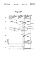
FIG. 11 shows a switching process in the prior art, in which (a) shows a frame structure of a receive signal, which is a TDM signal with three channels in each frame. In this embodiment, the third burst in each frame is the time slot assigned to the own station. The timing circuit 6-1 forwards to the receive level measurement circuit 6-3 a trigger signal at time t1 which is just before the beginning of the assigned time slot so that the receive level R1 at the antenna 1 is kept in the sample-hold circuit 6-4. Then, the switch control circuit 6-2 switches the selection switch 3 to the other antenna 2 so that the receive level R2 at the antenna 2 at time t2 is kept in the sample-hold circuit 6-5. The comparator 6-6 compares R1 with R2. The switch control circuit 6-2 selects the antenna which provides the higher receive level according to the result of the comparison, and keeps the switch 3 to receive the assigned time slot according to said comparison result.
For instance, assuming that the receive level in the antennas 1 and 2 changes as shown by the curves C1 and C2 in FIG. 11(b), the switch control circuit 6-2 forwards the selection signal as shown in FIG. 11(c), in which the curve (1) indicates the selection of the antenna 1, and the curve (2) shows the selection of the antenna 2. R1 is the level on the curve C1 just before the assigned time slot when the antenna 1 is selected, and R2 is the receive level on the curve C2 just before the assigned time slot when the antenna 2 is selected. As the level relations R1 >R2 is satisfied at time t1 (or t2) just before the assigned time slot, the antenna 1 is selected for receiving the assigned burst signal. The receive level is compared before each assigned slot, and an antenna which provides the higher receive level is selected so that the receive level applied to the receiver/demodulator 4 is kept high to prevent data error.
However, the prior art has the disadvantage that little diversity effect is obtained when fading rate is high, or the receive level changes rapidly. When the receive level changes after the levels R1 and R2 are measured at time t1 or t2, the selected antenna does not provide the higher receive level.
FIG. 11(d) and FIG. 11(e) show the above situation. When the receive levels of the antennas 1 and 2 change as shown in the curves C1 and C2 in FIG. 11(d), the relations R1 >R2 are satisfied at time t1 and t2, and therefore, the antenna 1 is selected for receiving the assigned burst signal. However, after the antenna is switched, the receive levels are reversed, and the selected antenna provides the lower receive signal. In that case, an error rate is not improved by an antenna selection diversity system.
As mentioned above, the prior system is not useful when fading rate is high.
SUMMARY OF THE INVENTION
It is an object, therefore, of the present invention to provide a new and improved antenna selection diversity receiver system which overcomes the disadvantages and limitations of a prior art.
It is also an object of the present invention to provide an antenna selection diversity receiver system which follows rapid fading rate.
The above and other objects are attained by an antenna selection diversity receiver system for TDM receive signal comprising; a plurality of antennas; a selection switch for selecting one of said antennas; a receiver/demodulator coupled with the selected antenna through said selection switch for providing demodulated receive signal and receive level; a frame synchronization circuit coupled with output of said receiver/demodulator for effecting frame synchronization of TDM signal; an antenna selection circuit coupled with output of said receiver/demodulator for receiving said receive level, and coupled with said selection switch for controlling said selection switch; wherein said antenna selection circuit comprises; a timing circuit coupled with said frame synchronization circuit for finding beginning of assigned time slot; first storage means for storing receive level of each antenna just before said assigned time slot; slope means for providing slope of said receive level of each antenna; second storage means for storing output of said slope means; prediction means for predicting receive signal quality of each antenna in said assigned time slot according to said receive level and said slope by using output of said first storage means and said second storage means; and a switch control circuit coupled with said timing circuit and said prediction means for switching said selection switch just before beginning of said assigned time slot for every assigned slots so that an antenna providing the best predicted receive signal quality in assigned time slot is selected.
BRIEF DESCRIPTION OF THE DRAWINGS
The foregoing and other objects, features, and attendant advantages of the present invention will be appreciated as the same become better understood by means of the following description and accompanying drawings wherein;
FIG. 1 is an operational flow chart of the first embodiment according to the present invention,
FIG. 2 is a block diagram of an antenna selection diversity receiver of the first embodiment according to the present invention,
FIG. 3A shows the operation of the antenna selection in the first embodiment of the present invention,
FIG. 3B shows the modification of FIG. 3A,
FIG. 3C shows another modification of FIG. 3A,
FIG. 4 shows the transient response of a differentiation circuit,
FIG. 5 is an operational flow chart of the second embodiment according to the present invention,
FIG. 6 is a block diagram of an antenna selection diversity receiver, of the second embodiment according to the present invention,
FIG. 7A shows the operation of the antenna selection in the second embodiment of the present invention,
FIG. 7B is the modification of FIG. 7A,
FIG. 8 is a block diagram of an antenna selection diversity receiver of the third embodiment of the present invention,
FIG. 9 shows the curves showing the effect of the present invention,
FIG. 10 is a block diagram of a prior diversity receiver, and
FIG. 11 shows operation of the antenna selection in the prior art.
DESCRIPTION OF THE PREFERRED EMBODIMENTS
FIG. 1 shows an operational flow chart of the first embodiment of the present invention, and FIG. 2 is a block diagram of the receiver according to the present invention. The same numerals in FIG. 2 as those in FIG. 10 show the same members. The numeral 7 in FIG. 2 is an antenna selection circuit, 7-1 is a timing circuit, 7-2 is a switch control circuit, 7-3 is a receive level measurement circuit, 7-4 is a receive level differentiation circuit, 7-5, 7-6, 7-8 and 7-9 are sample hold circuits, 7-7 is a differentiation circuit, and 7-10 is an error prediction circuit.
The receive signal on the antenna 1 or 2 is applied to the receiver/demodulator 4 through the selection circuit 3. The demodulated signal in the receiver/demodulator 4 is applied to the frame synchronization circuit 5 for the frame synchronization.
The antenna selection circuit 7 determines the assigned burst timing of the own station according to the frame timing signal from the frame synchronization circuit 5, and switches the selection switch 3 just before the beginning of the assigned slot so that the receive levels and the differentiating coeffecients of two antennas are measured.
FIG. 3A shows the operation of the antenna selection. FIG. 3A(a) shows the frame structure of a receive signal, and is the same as FIG. 11(a). The symbol S1, S2 and S3 show slots in the frame, and it is assumed in the present embodiment that the slot S3 is the assigned slot, and S1 and S2 are other slots of other channels.
The timing circuit 7-1 sends the receive level measurement circuit 7-3 a trigger signal at time t1 which is just before the receive timing of the assigned time slot S3 so that the receive level R1 by the selected antenna 1 at time t1 is kept in the sample hold circuit 7-5. Simultaneously, the trigger signal is sent to the receive level differention circuit 7-4 so that the differentiating coefficient dR1 which is obtained by differentiating the receive level of the antenna 1 by the differention circuit 7-7 is kept in the sample hold circuit 7-8 (102 in FIG. 1).
It should be appreciated that the receive levels R1 and R2 just before the assigned burst slot concern the receive signal of the time slot S2, which differs from the assigned time slot S3. In any event, the receive level in another time slot S2 is sufficient to predict the signal quality in the assigned time slot.
Then, the switch control circuit 7-2 switches the selection switch 3 to the other antenna 2 so that the receive level R2 and the differentiating coefficient dR2 at time t2 are kept in the sample hold circuits 7-6 and 7-9, respectively (104 in FIG. 1). The measured four values R1, R2, dR1 and dR2 are applied to the error rate prediction circuit 7-10, which predicts the receive level and the error rate in the assigned time slot S3. For instance, when the receive level of the antennas 1 and 2 change as shown in the curves C1 and C2 in FIG. 3A(b), the differentiating coefficients of the receive levels C1 and C2 are shown by the curves D1 and D2 in FIG. 3A(c).
The predicted receive levels r1 and r2 of each of the antennas, and the average error rates E1 and E2 of each of the antennas in the assigned time slot S3 which follows the measure time t1 and t2 are predicted as follows by using the values R1, R2, dR1 and dR2 (106 in FIG. 1).
r.sub.i (t)=R.sub.i +dR.sub.i (t-t.sub.i) (i=1,2)          (1) ##EQU1## where t.sub.s and t.sub.f are beginning time and end time of the assigned time slot S3, respectively, and P.sub.ei [r] is the error rate when the receive level is r.
For instance, when the differential encoded QPSK signal is detected through differential detection process, the theoretical error rate is; ##EQU2## where r0 is the receive level which provides the normarized signal to noise ratio (Eb /N0) to be equal to 1 at an input of a detector, where Eb is receive power for each signal bit, and N0 is noise power density.
The values r1, r2, E1 and E2 are predicted according to the above equations, and in the present embodiment, E1 >E2 is obtained as shown in FIG. A.3(d) and FIG. A.3(e) (108 in FIG. 1). The predicted error rate is applied to the switch control circuit 7-2, which selects the antenna 2 which provides the lower error rate, as shown in FIG. 3A(f) (112 in FIG. 1). Thus, the error rate when the assigned burst signal is received is kept low. The antenna 1 would be selected when E1 ≦E2 is satisfied.
When the receive operation in the assigned time slot S3 finishes (114 in FIG. 1), the operation returns to the box 102 in FIG. 1 so that the similar operation is repeated for the succeeding frames.
It should be noted that that as the assigned slot is S3 in the present embodiment, the measurement is carried out during the slot S2 which is just before the assigned time slot. When the assigned time slot is S2, the measurement is of course carried out during the slot S1 which is just before the assigned time slot.
The curve of the receive level in FIG. 3A(b) is the same as that of FIG. 11(d). In the prior art of FIG. 11(d), the antenna 1 is selected, and therefore, the error rate in the assigned burst timing is high. On the other hand, as the present invention selects the antenna 2, the low error rate is obtained.
As mentioned above, according to the above embodiment, the antenna is selected according to the predicted average error rate of each of the antennas calculated by using the receive level and the differentiating coefficient of the receive level of each of the antennas. Therefore, the antenna which provides the lower error rate in the assigned burst timing is selected even when the receive levels are reversed after the receive levels (R1, R2) are measured. Thus, the effect of the diversity reception is improved.
FIG. 3B shows the modification of the embodiment of FIG. 3A, and the same numerals in FIG. 3B show the same members as those in FIG. 3A. The feature of FIG. 3B is that the antenna is selected so that the receive level at the center of the assigned time slot or the average receive level during the slot is higher than that of the other antenna.
The receive level (M1, M2) at the center of the assigned time slot by each antenna is as follows.
M.sub.i =R.sub.i +dR.sub.i ((t.sub.s +t.sub.f)/2-t.sub.i)  (i=1 or 2) (2A)
Mi also presents the average receive level during the assigned time slot. The above equation (2A) is used for the selection of the antenna, instead of the equation (2). It should be noted in FIG. 3B that the receive levels M1 and M2 are predicted on the assumption that the receive level changes linearly.
FIG. 3C shows another modification of the embodiment of FIG. 3A, and the same numerals in FIG. 3C show the same members as those in FIG. 3A. The feature of the FIG. 3C is that the antenna is selected depending upon the minimum receive level during the assigned time slot S3 so that the minumum receive level of the selected antenna is higher than the minumum receive level of the other antenna.
The minimum receive level L1 for the antenna 1, and the minimum receive level L2 for the second antenna 2 are predicted as follows. ##EQU3##
In three modifications in FIG. 3A, FIG. 3B and FIG. 3C, the antenna 2 is selected in the assigned time slot S3.
Next, the transient response of a differentiating circuit is discussed.
FIGS. 4(a) and 4(b) show the same signal levels as those of FIGS. 3A(a) and 3A(b). The thick lines in FIG. 4(a) and FIG. 4(b) show the receive level provided at the output of the receiver/demodulator 4 in FIG. 2, and the differentiated value provided at the output of the differentiating circuit 7-7, respectively. When the antennas are switched from the antenna 1 to the antenna 2 between the time t1 and the time t2, the receive level at the output of the selection switch 3 has the uncontinuous step by the level (R2 -R1) Because of that step of the receive level, the differentiating waveform of the receive level has the transient response I in the form of negative impulse as shown in FIG. 4(b). Although the transient response converges in a short time, the differentiating coefficient dR2 ' measured just after the switching must include not only the desired differentiating coefficient dR2 but also said transient response. When the transient error is large, the measured values of r2 and E.sub. 2 in the equations (1) and (2) must also have the large error, and the correct antenna selection is impossible. The larger the value (R2 -R1) is, the larger the transient error is. As the transient error becomes small when the duration between the switching time and the measurement time t2 is long, it would be preferable to take t2 -t1 longer. However, when that time t2 -t1 is too long, the error rate E1 which is predicted by using dR1 at time t1 would have large error since the value dR1 itself would change until the assigned burst slot time due to rapid fading.
FIGS. 5 and 6 show the second embodiment of the present invention for overcoming the above problem. FIG. 5 shows the operational flow diagram, and FIG. 6 shows a block diagram of a receiver. In FIG. 6, the numerals 7-2, 7-3, 7-5 and 7-6 are the same as those in FIG. 2, and 7-11 is a timing circuit, and 7-12 is a receive level difference measurement circuit. The numerals 7-13 and 7-14 are sample hold circuits, 7-15 and 7-16 are subtractors, and 7-17 is an error prediction circuit. The feature of the embodiment of FIG. 6 is to measure the receive level twice for each antenna, instead of the use of a differentiating circuit. The difference of two measured receive levels is used instead of the differenting coefficient.
FIG. 7A shows the operation of the antenna selection in the second embodiment. FIG. 7A(a) shows the frame structure, which is the same as that of FIG. 3A(a). The timing circuit 7-11 forwards the receive level difference measurement circuit 7-12 a trigger signal at time t3 which is a little before the beginning of the assigned burst signal so that the receive level R3 at time t3 in the antenna 1 is kept in the sample hold circuit 7-13. Then, the switch control circuit 7-2 switches the selection switch 3 to the other antenna 2 at time t4 which is immediate after the time t3 so that the receive level R4 in the antenna 2 is kept in the sample hold circuit 7-14. Next, the antenna 1 is connected again, and the receive level R1 in the antenna 1 at time t1 is kept in the sample hold circuit 7-5. Finally, the antenna is again switched to the antenna 2, and the receive level R2 in the antenna 2 at time t2 is kept in the sample hold circuit 7-6. Thus, four receive levels R1 through R4 are obtained as shown in FIG. 7A(b) (152 in FIG. 5).
The receive level difference measurement circuit 7-12 calculates the differences ΔR1 (=R1 -R3), and ΔR2 (=R2 -R4) for each of the antennas by using the subtractors 7-15 and 7-16 (154 in FIG. 5). The error prediction circuit 7-17 predicts the receive levels r1 and r2 for each of the antennas in the assigned time slot by using above values R1, R2, ΔR1 and ΔR2 as follows. ##EQU4## The values r1 and r2 thus obtained are shown in FIG. 7A(c), and those values are used for providing the error rates E1 and E2 in the equation (2), and the results are shown in FIG. 7A(d) (156 in FIG. 5). As E1 >E2 is satisfied in FIG. 7A(d) (158 in FIG. 5), the switch control circuit 7-2 selects the antenna 2 as shown in FIG. 7A(e) (162 in FIG. 5). If E1 ≦E2 is satisfied, the antenna 1 is selected (160 in FIG. 5). Thus, the average error rate at the assigned time slot is kept low.
When the receive operation in the assigned time slot S3 finishes (164 in FIG. 5), the operation returns to the box 152 in FIG. 5 so that the similar operation is repeated for the succeeding frames.
It should be appreciated that the concept of FIG. 7A which uses a subtractor instead of a differentiation circuit may be combined with the concept of FIG. 3B which uses the receive level of each antenna at center of an assigned slot, and/or the concept of FIG. 3C which uses the minimum receive level of each antenna as criteria of the selection of antennas.
When the concept of FIG. 7A is combined with the concept of FIG. 3B, the receive level Mi of each antenna (i=1 or 2) at the center of the assigned slot is calculated as follows. ##EQU5## When the concept of FIG. 7A is combined with the concept of FIG. 3C, the minimum receive level Li in the assigned slot is predicted according to the following equation. ##EQU6## FIG. 7B shows the modification of FIG. 7A, and the feature of the modification of FIG. 7B is to measure the receive level more than three times for each antenna, and the prediction of the receive level in an assigned slot is carried out non-linearly, while the embodiment of FIG. 7A predicts the receive level in the assigned time slot linearly.
In the modification of FIG. 7B, the measurement of receive level is carried out three times for each antenna, and the receive levels R3, R5 and R1 are obtained for the antenna 1, and the receive levels R4, R6 and R2 are obtained for the antenna 2. The receive level r1 for the antenna 1 in an assigned slot, and the receive level r2 for the antenna 2 in an assigned slot are predicted by using those measured receive levels. In case of three measured values, the predicted curve is quadratic. The average error rate is then calculated by using the equation (2), and the antenna selection is carried out so that the antenna which provides the lower average error rate is selected.
It should be appreciated of course that the concept of FIG. 7B may be combined with the concepts of FIG. 3B and/or FIG. 3C. In other words, the criteria of the selection of the antennas may be the receive level at the center of the assigned time slot of each antenna predicted by using more than three measured receive levels, and/or the minimum recieve level in the assigned burst slot predicted by using more than three measured receive levels.
FIG. 8 is a block diagram of the third embodiment of the present invention. The feature of FIG. 8 is that the main portion of the embodiment of FIG. 6 is implemented by digital circuits. In FIG. 6 embodiment, the receive levels R1 through R4 are kept in four sample hold circuits, on the other hand, in FIG. 8 embodiment, a single A/D converter 7-19 measures the receive levels at times t1 through t4 four times, and the measured values are stored in four registers 7-20 through 7-23.
The registers 7-20 and 7-21 provide the receive levels R1 and R2, respectively, and the digital subtractors 7-24 and 7-25 calculate the receive level differences ΔR1 and ΔR2. Therefore, the receive level measurement circuit 7-18 in FIG. 8 is equivalent to the receive level measurement circuit 7-3 and receive level difference measurement circuit 7-12 in FIG. 6. The circuit 7-18 in FIG. 8 provide the values R1, R2, ΔR1, and ΔR2 in digital form. The average error rates E1 and E2 are predicted as is the case of FIG. 6, and the antenna which provides the lower error rate is selected. The error rate prediction circuit 7-17 receives R1, R2, ΔR1 and ΔR2 in quantized digital form each having n bits. For example, the error rate prediction circuit 7-17 can be implemented by a ROM (read only memory), which has address input terminals with 4n bits, and each address of the ROM stores the result of the comparison of E1 and E2. The embodiment of FIG. 8 implements the process of R1 through R4, E1 and E4 in digital form, and therefore, the circuit is implemented easily by using an IC.
The digital subtractors 7-24 and 7-25 may be removed if the error rate prediction circuit 7-17 carries out the function of those subtractors. In that case, the error rate prediction circuit 7-17 receives R1 through R4 in quantized digital form. For instance, when R1 through R4 are applied to 4n bits of address terminals of a ROM, which stores the result of the comparison of E1 and E2 corresponding to each input values, the error rate prediction circuit 7-17, and the subtractors 7-24 and 7-25 are implemented by a single ROM.
It should be appreciated that the present invention is applicable to a diversity receiver which has more than three antennas, although the above embodiments have two antennas. When there are more than three antennas in the embodiment of FIG. 2, the calculation of the equations (1) and (2) is carried out for each antenna, and the antenna which provides the lowest error rate is selected. In case of the embodiment of FIG. 6 or FIG. 8, the receive level for each antenna is measured twice, and the calculation of the equation (4) is carried out for each antenna, and the result is inserted into the equation (2) so that the antenna which provides the lowest average error rate is selected.
It should be appreciated of course that the concept of a digital circuit is applicable to not only to the embodiment of FIG. 6, but also to any one of the above embodiments and modifications.
FIG. 9 shows the simulated performance curve which shows the effect of the present invention. In the figure, the horizontal axis shows the fading frequency in Hz, and the vertical axis shows the diversity gain in dB, which is defined to be the input level difference between a diversity receiver and an ordinary (not diversity) receiver for providing an error rate of 1%. The solid line in FIG. 9 shows the curve of the present invention, and the dotted curve shows that of the prior art of FIG. 10. As apparent in FIG. 9, the diversity gain of the present invention is always higher than that of the prior art in any fading frequency.
As mentioned above, according to the present invention, an antenna diversity receiver which provides an excellent diversity effect in high fading rate is obtained. Therefore, when a receiver is mounted on a moving mobile, an excellent diversity effect is obtained, and therefore, the present invention may be used in many mobile communication systems. The reception capability of a receiver is improved considerably by using the present invention.
The present invention may replace a conventional diversity receiver which has two receivers selected at the output of detectors, and in that case, a receiver may be improved in size, and power consumption, since the present invention uses only one receiver.
From the foregoing, it will now be apparent that a new and improved antenna diversity system has been found. It should be understood of course that the embodiments disclosed are merely illustrative and are not intended to limit the scope of the invention. Reference should be made to the appended claims, therefore, rather than the specification as indicating the scope of the invention.

Claims (8)

What is claimed is:
1. An antenna selection diversity receiver system for a TDM receive signal comprising:
a plurality of antennas,
a selection switch for selecting one of said antennas,
a receiver/demodulator coupled with the selected antenna through said selection switch for providing a demodulated receive signal and a receive level,
a frame synchronization circuit coupled with output of said receiver/demodulator for effecting frame synchronization of said TDM signal,
an antenna selection circuit coupled with output of said receiver/demodulator for receiving said receive level, and coupled with said selection switch for controlling said selection switch,
said antenna selection circuit comprising;
a timing circuit coupled with said frame synchronization circuit for finding a beginning of an assigned time slot,
first storage means for storing said receive level of each antenna just before said assigned time slot,
slope means for providing a slope of said receive level of each antenna,
second storage means for storing output of said slope means,
prediction means for predicting receive signal quality of each antenna in said assigned time slot according to said receive level and said slope by using output of said first storage means and said second storage means, and
a switch control circuit coupled with said timing circuit and said prediction means for switching said selection switch just before a beginning of said assigned time slot for every assigned slot so that an antenna providing the best predicted receive signal quality in said assigned time slot is selected.
2. An antenna selection diversity receiver system according to claim 1, wherein said slope means is a differentiation circuit.
3. An antenna selection diversity receiver system according to claim 1, wherein said slope means comprises a subtractor for providing a difference of two receive levels at different times for each antenna.
4. An antenna selection diversity receiver system according to claim 1, wherein said first storage means and said second storage means are implemented by a digital register, and said slope means and said predictor means are implemented by a ROM.
5. An antenna selection diversity receiver system according to claim 1, wherein said prediction means predicts an average error rate of each antenna in said assigned time slot as said receive signal quality.
6. An antenna selection diversity receiver system according to claim 1, wherein said prediction means predicts said receive level of each antenna at the center of the assigned time slot as said receive signal quality.
7. An antenna selection diversity receiver system according to claim 1, wherein said prediction means predicts the minimum receive level of each antenna in the assigned time slot as said receive signal quality.
8. An antenna selection diversity receiver system according to claim 1, wherein more than three receive levels for each antenna are measured for prediction of receive signal quality in said assigned time slot.
US07/691,295 1990-04-27 1991-04-25 Antenna selection diversity reception system Expired - Lifetime US5203024A (en)

Applications Claiming Priority (6)

Application Number Priority Date Filing Date Title
JP2114244A JPH0411415A (en) 1990-04-27 1990-04-27 Antenna selection diversity reception system
JP2-114244 1990-04-27
JP2-110517 1990-04-27
JP2-114245 1990-04-27
JP2114245A JPH0411416A (en) 1990-04-27 1990-04-27 Antenna selection diversity reception system
JP2110517A JPH0410724A (en) 1990-04-27 1990-04-27 Method for receiving antenna selecting diversity and receiver based upon the same

Publications (1)

Publication Number Publication Date
US5203024A true US5203024A (en) 1993-04-13

Family

ID=27311755

Family Applications (1)

Application Number Title Priority Date Filing Date
US07/691,295 Expired - Lifetime US5203024A (en) 1990-04-27 1991-04-25 Antenna selection diversity reception system

Country Status (5)

Country Link
US (1) US5203024A (en)
EP (1) EP0454585B1 (en)
JP (1) JPH06103845B2 (en)
CA (1) CA2041283C (en)
DE (1) DE69103196T2 (en)

Cited By (33)

* Cited by examiner, † Cited by third party
Publication number Priority date Publication date Assignee Title
US5369801A (en) * 1992-09-25 1994-11-29 Northern Telecom Limited Antenna diversity reception in wireless personal communications
WO1995033312A1 (en) * 1994-06-01 1995-12-07 Motorola Inc. A method for selecting two antennas
US5499397A (en) * 1994-05-02 1996-03-12 Motorola, Inc. Switched antenna diversity algorithm employing received signal strength, phase errors and recovered clock
US5530926A (en) * 1993-10-04 1996-06-25 Motorola, Inc. Method for operating a switched diversity RF receiver
US5530925A (en) * 1993-08-02 1996-06-25 Harris Corporation Intermediate frequency combiner for a radio communication system
US5533027A (en) * 1993-02-16 1996-07-02 Telefonaktiebolaget Lm Ericsson Digital fixed radio access system providing local mobility
US5557609A (en) * 1993-12-01 1996-09-17 Kabushiki Kaisha Toshiba Switching apparatus for ATM
US5561673A (en) * 1993-04-16 1996-10-01 Matsushita Electric Industrial Co., Ltd. Antenna switched diversity reciever
US5574750A (en) * 1993-09-14 1996-11-12 Pacific Communication Sciences, Inc. Methods and apparatus for detecting a cellular digital packet data (CDPD) carrier
WO1997013378A2 (en) * 1995-10-01 1997-04-10 Geotek Communications, Inc. Apparatus and method for determining and using channel state information
US5648992A (en) * 1993-09-30 1997-07-15 Rockwell Semiconductor Systems, Inc. Multiple antenna home base for digital cordless telephones
US5842118A (en) * 1996-12-18 1998-11-24 Micron Communications, Inc. Communication system including diversity antenna queuing
US5854808A (en) * 1993-09-14 1998-12-29 Pacific Communication Sciences Methods and apparatus for detecting the presence of a prescribed signal in a channel of a communications system
US5960046A (en) * 1996-12-03 1999-09-28 Northern Telecom Limited Preamble based selection diversity in a time division multiple access radio system
US6002672A (en) * 1996-10-25 1999-12-14 Nortel Networks Corporation Diversity antenna selection
US6032033A (en) * 1996-12-03 2000-02-29 Nortel Networks Corporation Preamble based selection diversity in a time division multiple access radio system using digital demodulation
US6115367A (en) * 1997-08-05 2000-09-05 Vlsi Technology, Inc. Methods of analyzing a radio signal and methods of analyzing a personal handy-phone system radio signal
US6172970B1 (en) * 1997-05-05 2001-01-09 The Hong Kong University Of Science And Technology Low-complexity antenna diversity receiver
US6289209B1 (en) 1996-12-18 2001-09-11 Micron Technology, Inc. Wireless communication system, radio frequency communications system, wireless communications method, radio frequency communications method
US20010055959A1 (en) * 1997-12-30 2001-12-27 Qun Shen Unified antenna diversity switching system for TDMA-based telephones
US6360088B1 (en) * 1998-09-23 2002-03-19 Ericsson Inc. Antenna diversity switching system and method for selecting an antenna through a programmed evaluation
US6574461B1 (en) * 1997-06-19 2003-06-03 Telefonaktiebolaget Lm Ericsson (Publ) Balanced diversity
US20030198302A1 (en) * 2002-04-17 2003-10-23 Wireless Interface Technologies, Inc. DC-tolerant bit slicer and method
US20040106388A1 (en) * 2002-12-03 2004-06-03 Kyu Sang Ro Method for processing radio waves, and audio system utilizing the method
US20050148306A1 (en) * 2004-01-05 2005-07-07 Hiddink Gerrit W. Predictive method and apparatus for antenna selection in a wireless communication system
US20050153673A1 (en) * 2004-01-14 2005-07-14 Nec Corporation Antenna-switching diversity receiver capable of switching antennas without deterioration of reception characteristic even when applied to the CDMA communication method
US20080085739A1 (en) * 2002-09-20 2008-04-10 Sanyo Electric Co., Ltd. Adaptive array wireless communication apparatus, reception level display method, reception level adjusting method, reception level display program and reception level adjusting program
US20080240280A1 (en) * 2007-04-02 2008-10-02 Apacewave Technologies Corporation Intelligent Iterative Switch Diversity
US20130017797A1 (en) * 2011-07-13 2013-01-17 Apple Inc. Selective receive diversity in a mobile wireless device
US20140119344A1 (en) * 2012-10-31 2014-05-01 Qualcomm Incorporated Adaptive allocation of idle slots based on error rate
US9271170B1 (en) 2012-05-01 2016-02-23 KCF Technologies Incorporated Channel adaptation in sensor networks
US10291310B1 (en) * 2018-04-09 2019-05-14 Qualcomm Incorporated Gap-based antenna measurement for antenna switch diversity
US10362636B2 (en) * 2011-07-24 2019-07-23 Ethertronics, Inc. Antennas configured for self-learning algorithms and related methods

Families Citing this family (24)

* Cited by examiner, † Cited by third party
Publication number Priority date Publication date Assignee Title
FI934052A (en) * 1993-09-15 1995-03-16 Nokia Telecommunications Oy Procedure furthermore monitors the function of a radio receiver unit as well as a radio receiver unit
SE9402493L (en) * 1994-07-15 1996-01-16 Ericsson Telefon Ab L M Method in a diversity receiver
WO1996008089A1 (en) * 1994-09-02 1996-03-14 Nokia Telecommunications Oy A method for improving connection quality in a cellular radio system and a receiver unit
US5628052A (en) * 1994-09-12 1997-05-06 Lucent Technologies Inc. Wireless communication system using distributed switched antennas
JPH09507371A (en) * 1994-10-17 1997-07-22 フィリップス エレクトロニクス ネムローゼ フェンノートシャップ Wireless digital communication system, wireless device, digital speaker, and digital speaker control device
GB2299734B (en) * 1995-04-03 1999-10-27 Motorola As Method of switching in signal selecting system
EP0741466A3 (en) * 1995-05-03 1996-12-18 Hughes Aircraft Co Method and apparatus for adaptive antenna selection in a mobile radio communications system
EP0755131A3 (en) * 1995-07-17 1999-05-06 Hagenuk Gmbh Apparatus for controlling antennas
DE19530021C2 (en) * 1995-07-17 1999-07-29 Hagenuk Telecom Gmbh Method and device for controlling antennas
JPH0964639A (en) * 1995-08-25 1997-03-07 Uniden Corp Diversity antenna circuit
GB2308530B (en) * 1995-12-21 2000-03-22 Nokia Mobile Phones Ltd Antenna selection control circuitry
GB2311693B (en) 1996-03-29 2000-06-21 Nokia Mobile Phones Ltd Antenna selection control circuitry
US5903596A (en) * 1996-05-16 1999-05-11 Nakano; Takayuki Spread spectrum demodulation unit
JP3380481B2 (en) * 1998-12-17 2003-02-24 松下電器産業株式会社 Base station equipment
US7024168B1 (en) 1999-07-07 2006-04-04 Telefonaktiebolaget L M Ericsson (Publ) Controlled antenna diversity
GB0105019D0 (en) * 2001-03-01 2001-04-18 Koninkl Philips Electronics Nv Antenna diversity in a wireless local area network
DE102006006266A1 (en) * 2005-02-13 2006-08-24 Lindenmeier, Heinz, Prof. Dr. Ing. Reception system for receiving digitally modulated radio signals on moving vehicle, updates reference phase when phase reference signal that carries current reference phase related to reference signal occurs
CN100362420C (en) * 2005-07-27 2008-01-16 大连理工大学 Method for improving optical characteristics of rare earth mixed aluminum oxide thin film utilizing laser annealing
GB0519582D0 (en) 2005-09-26 2005-11-02 Cambridge Silicon Radio Ltd Antenna diversity
KR101532526B1 (en) * 2008-02-01 2015-06-29 애플 인크. System and method for spatial multiplexing-based multiple antenna broadcast/multicast transmission
US7933363B2 (en) 2008-04-18 2011-04-26 Cambridge Silicon Radio Limited Polarization diversity
JP4820387B2 (en) * 2008-06-05 2011-11-24 日本放送協会 Diversity receiver
CN102468888B (en) * 2010-11-08 2016-04-20 中兴通讯股份有限公司 The method of receive antennae diversity fault detect and device
FR3016260B1 (en) 2014-01-06 2016-02-05 Commissariat Energie Atomique TIME-SYNCHRONIZATION MULTI-ANTENNA RECEIVER COMMON TO THE DIFFERENT RECEIVE CHAINS

Citations (4)

* Cited by examiner, † Cited by third party
Publication number Priority date Publication date Assignee Title
US4613975A (en) * 1983-08-26 1986-09-23 Nec Corporation Selective fading protection system
US4719649A (en) * 1985-11-22 1988-01-12 Sanders Associates, Inc. Autoregressive peek-through comjammer and method
US4742567A (en) * 1985-02-01 1988-05-03 Toyota Jidosha Kabushiki Kaisha Automobile antenna system
US4977616A (en) * 1987-11-30 1990-12-11 Motorola, Inc. Antenna selection control circuit

Family Cites Families (3)

* Cited by examiner, † Cited by third party
Publication number Priority date Publication date Assignee Title
JPS5732535B2 (en) * 1975-02-17 1982-07-12
US4513412A (en) * 1983-04-25 1985-04-23 At&T Bell Laboratories Time division adaptive retransmission technique for portable radio telephones
CA1292584C (en) * 1987-11-30 1991-11-26 Henry Ludwig Kazecki Antenna selection control circuit

Patent Citations (4)

* Cited by examiner, † Cited by third party
Publication number Priority date Publication date Assignee Title
US4613975A (en) * 1983-08-26 1986-09-23 Nec Corporation Selective fading protection system
US4742567A (en) * 1985-02-01 1988-05-03 Toyota Jidosha Kabushiki Kaisha Automobile antenna system
US4719649A (en) * 1985-11-22 1988-01-12 Sanders Associates, Inc. Autoregressive peek-through comjammer and method
US4977616A (en) * 1987-11-30 1990-12-11 Motorola, Inc. Antenna selection control circuit

Non-Patent Citations (4)

* Cited by examiner, † Cited by third party
Title
Afrashteh et al., "Performance of a Novel Selection Diversity Technique in an Experimental TDMA System for Digital Portable Radio Communications", IEEE Global Communication Conference 1988, pp. 26.2.1-26.2.5.
Afrashteh et al., Performance of a Novel Selection Diversity Technique in an Experimental TDMA System for Digital Portable Radio Communications , IEEE Global Communication Conference 1988, pp. 26.2.1 26.2.5. *
Yamao et al., "Predictive Antenna Selection Diversity (PASD) for TDMA Mobile Radio", Yasushi Yamao and Yoshinori Nagao, NTT Radio Communication Systems Laboratories, Mar. 1991, pp. 46.4.1-46.4.5.
Yamao et al., Predictive Antenna Selection Diversity (PASD) for TDMA Mobile Radio , Yasushi Yamao and Yoshinori Nagao, NTT Radio Communication Systems Laboratories, Mar. 1991, pp. 46.4.1 46.4.5. *

Cited By (46)

* Cited by examiner, † Cited by third party
Publication number Priority date Publication date Assignee Title
US5369801A (en) * 1992-09-25 1994-11-29 Northern Telecom Limited Antenna diversity reception in wireless personal communications
US5533027A (en) * 1993-02-16 1996-07-02 Telefonaktiebolaget Lm Ericsson Digital fixed radio access system providing local mobility
US5561673A (en) * 1993-04-16 1996-10-01 Matsushita Electric Industrial Co., Ltd. Antenna switched diversity reciever
US5530925A (en) * 1993-08-02 1996-06-25 Harris Corporation Intermediate frequency combiner for a radio communication system
US5854808A (en) * 1993-09-14 1998-12-29 Pacific Communication Sciences Methods and apparatus for detecting the presence of a prescribed signal in a channel of a communications system
US5719902A (en) * 1993-09-14 1998-02-17 Pacific Communication Sciences, Inc. Methods and apparatus for detecting cellular digital packet data (CDPD)
US5574750A (en) * 1993-09-14 1996-11-12 Pacific Communication Sciences, Inc. Methods and apparatus for detecting a cellular digital packet data (CDPD) carrier
US5648992A (en) * 1993-09-30 1997-07-15 Rockwell Semiconductor Systems, Inc. Multiple antenna home base for digital cordless telephones
US5530926A (en) * 1993-10-04 1996-06-25 Motorola, Inc. Method for operating a switched diversity RF receiver
US5557609A (en) * 1993-12-01 1996-09-17 Kabushiki Kaisha Toshiba Switching apparatus for ATM
US5499397A (en) * 1994-05-02 1996-03-12 Motorola, Inc. Switched antenna diversity algorithm employing received signal strength, phase errors and recovered clock
WO1995033312A1 (en) * 1994-06-01 1995-12-07 Motorola Inc. A method for selecting two antennas
US5740526A (en) * 1994-06-01 1998-04-14 Bonta; Jeffrey D. Method and apparatus for selecting two antennas from which to receive a communication signal
WO1997013378A2 (en) * 1995-10-01 1997-04-10 Geotek Communications, Inc. Apparatus and method for determining and using channel state information
WO1997013378A3 (en) * 1995-10-01 1997-06-05 Geotek Communications Inc Apparatus and method for determining and using channel state information
US6002672A (en) * 1996-10-25 1999-12-14 Nortel Networks Corporation Diversity antenna selection
US6118773A (en) * 1996-10-25 2000-09-12 Nortel Networks Corporation Impairment determination for a diversity antenna selection process
US5960046A (en) * 1996-12-03 1999-09-28 Northern Telecom Limited Preamble based selection diversity in a time division multiple access radio system
US6032033A (en) * 1996-12-03 2000-02-29 Nortel Networks Corporation Preamble based selection diversity in a time division multiple access radio system using digital demodulation
US6023610A (en) * 1996-12-18 2000-02-08 Micron Technology, Inc. Communication system including diversity antenna queuing
US6466771B2 (en) 1996-12-18 2002-10-15 Micron Technology, Inc. Wireless communication system, radio frequency communications system, wireless communications method, radio frequency communications method, and backscatter radio frequency communications system
US5842118A (en) * 1996-12-18 1998-11-24 Micron Communications, Inc. Communication system including diversity antenna queuing
US6351630B2 (en) 1996-12-18 2002-02-26 Micron Technology, Inc. Wireless communication system, radio frequency communications system, wireless communications method, radio frequency communications method, and backscatter radio frequency communications system
US6289209B1 (en) 1996-12-18 2001-09-11 Micron Technology, Inc. Wireless communication system, radio frequency communications system, wireless communications method, radio frequency communications method
US6172970B1 (en) * 1997-05-05 2001-01-09 The Hong Kong University Of Science And Technology Low-complexity antenna diversity receiver
US6574461B1 (en) * 1997-06-19 2003-06-03 Telefonaktiebolaget Lm Ericsson (Publ) Balanced diversity
US6115367A (en) * 1997-08-05 2000-09-05 Vlsi Technology, Inc. Methods of analyzing a radio signal and methods of analyzing a personal handy-phone system radio signal
US6847810B2 (en) * 1997-12-30 2005-01-25 Ericsson Inc. Unified antenna diversity switching system for TDMA-based telephones
US20010055959A1 (en) * 1997-12-30 2001-12-27 Qun Shen Unified antenna diversity switching system for TDMA-based telephones
US6360088B1 (en) * 1998-09-23 2002-03-19 Ericsson Inc. Antenna diversity switching system and method for selecting an antenna through a programmed evaluation
US20030198302A1 (en) * 2002-04-17 2003-10-23 Wireless Interface Technologies, Inc. DC-tolerant bit slicer and method
US20080085739A1 (en) * 2002-09-20 2008-04-10 Sanyo Electric Co., Ltd. Adaptive array wireless communication apparatus, reception level display method, reception level adjusting method, reception level display program and reception level adjusting program
US8024002B2 (en) * 2002-09-20 2011-09-20 Kyocera Corporation Adaptive array wireless communication apparatus, reception level display method, reception level adjusting method, reception level display program and reception level adjusting program
US20040106388A1 (en) * 2002-12-03 2004-06-03 Kyu Sang Ro Method for processing radio waves, and audio system utilizing the method
US7068986B2 (en) * 2002-12-03 2006-06-27 Hyundai Motor Company Method for processing radio waves, and audio system utilizing the method
US20050148306A1 (en) * 2004-01-05 2005-07-07 Hiddink Gerrit W. Predictive method and apparatus for antenna selection in a wireless communication system
US7315733B2 (en) * 2004-01-14 2008-01-01 Nec Corporation Antenna-switching diversity receiver capable of switching antennas without deterioration of reception characteristic even when applied to the CDMA communication method
US20050153673A1 (en) * 2004-01-14 2005-07-14 Nec Corporation Antenna-switching diversity receiver capable of switching antennas without deterioration of reception characteristic even when applied to the CDMA communication method
US20080240280A1 (en) * 2007-04-02 2008-10-02 Apacewave Technologies Corporation Intelligent Iterative Switch Diversity
US20130017797A1 (en) * 2011-07-13 2013-01-17 Apple Inc. Selective receive diversity in a mobile wireless device
US8761701B2 (en) * 2011-07-13 2014-06-24 Apple Inc. Selective receive diversity in a mobile wireless device
TWI495287B (en) * 2011-07-13 2015-08-01 Apple Inc Selective receive diversity in a mobile wireless device
US10362636B2 (en) * 2011-07-24 2019-07-23 Ethertronics, Inc. Antennas configured for self-learning algorithms and related methods
US9271170B1 (en) 2012-05-01 2016-02-23 KCF Technologies Incorporated Channel adaptation in sensor networks
US20140119344A1 (en) * 2012-10-31 2014-05-01 Qualcomm Incorporated Adaptive allocation of idle slots based on error rate
US10291310B1 (en) * 2018-04-09 2019-05-14 Qualcomm Incorporated Gap-based antenna measurement for antenna switch diversity

Also Published As

Publication number Publication date
JPH06103845B2 (en) 1994-12-14
JPH0645970A (en) 1994-02-18
DE69103196D1 (en) 1994-09-08
CA2041283C (en) 1994-05-03
EP0454585A1 (en) 1991-10-30
CA2041283A1 (en) 1991-10-28
EP0454585B1 (en) 1994-08-03
DE69103196T2 (en) 1995-02-23

Similar Documents

Publication Publication Date Title
US5203024A (en) Antenna selection diversity reception system
CA2035167C (en) Antenna selection diversity reception apparatus
US5561673A (en) Antenna switched diversity reciever
US6128355A (en) Selective diversity combining
US4953197A (en) Combination spatial diversity system
US5291519A (en) Digital mobile communications terminal equipment and receiving method therefor
US5488638A (en) Clock recovery method and apparatus in a diversity receiver
US5774810A (en) Mobile radio communication device
KR20010051111A (en) Reception apparatus and reception processing method
JP3070239B2 (en) Electronic control antenna system
JP2003046418A (en) Diversity receiver
JP2991170B2 (en) CDMA receiver and method
EP1044516B1 (en) Tstd transmitter for limiting transmission power of antenna and controlling method thereof for base station in mobile communication system
JP2001257632A (en) Time division multiple access(tdma) communication system provided with adaptive equalization function
US6212371B1 (en) Mobile wireless terminal and power controlling method
EP0730801A1 (en) Receiver path selection based on burst-type in a time division multiple access receiver
EP0741466A2 (en) Method and apparatus for adaptive antenna selection in a mobile radio communications system
US7095711B1 (en) Communication method and apparatus for a radio local area network system using macrodiversity
JPH088809A (en) Diversity receiver
JPH02200020A (en) Antenna switching diversity system
JPH05206903A (en) Diversity device
JPH08251090A (en) Transmission diversity device
JPH0410724A (en) Method for receiving antenna selecting diversity and receiver based upon the same
JPH05167482A (en) Space diversity controller
MXPA99010615A (en) Selective diversity combining

Legal Events

Date Code Title Description
AS Assignment

Owner name: NIPPON TELEGRAPH AND TELEPHONS CORPORATION, JAPAN

Free format text: ASSIGNMENT OF ASSIGNORS INTEREST.;ASSIGNOR:YAMAO, YASUSHI;REEL/FRAME:005686/0507

Effective date: 19910410

STCF Information on status: patent grant

Free format text: PATENTED CASE

AS Assignment

Owner name: NTT MOBILE COMMUNICATIONS NETWORK, INC., JAPAN

Free format text: ASSIGNMENT OF ASSIGNORS INTEREST;ASSIGNOR:NIPPON TELEGRAPH AND TELEPHONE CORPORATION;REEL/FRAME:006794/0615

Effective date: 19931130

AS Assignment

Owner name: NIPON TELEGRAPH AND TELEPHONE CORPORATION, JAPAN

Free format text: CHANGE OF ADDRESS;ASSIGNOR:NIPPON TELEGRAPH AND TELEPHONE CORPORATION;REEL/FRAME:008133/0724

Effective date: 19951018

FPAY Fee payment

Year of fee payment: 4

FPAY Fee payment

Year of fee payment: 8

FPAY Fee payment

Year of fee payment: 12