US5210571A - System for servicing electronic printers and printing systems - Google Patents
System for servicing electronic printers and printing systems Download PDFInfo
- Publication number
- US5210571A US5210571A US07/766,231 US76623191A US5210571A US 5210571 A US5210571 A US 5210571A US 76623191 A US76623191 A US 76623191A US 5210571 A US5210571 A US 5210571A
- Authority
- US
- United States
- Prior art keywords
- job
- test
- technician
- special
- Prior art date
- Legal status (The legal status is an assumption and is not a legal conclusion. Google has not performed a legal analysis and makes no representation as to the accuracy of the status listed.)
- Expired - Lifetime
Links
- 238000007639 printing Methods 0.000 title claims abstract description 36
- 238000012360 testing method Methods 0.000 claims abstract description 51
- 238000000034 method Methods 0.000 claims abstract description 19
- 230000008569 process Effects 0.000 claims abstract description 17
- 230000002708 enhancing effect Effects 0.000 claims abstract description 5
- 230000006835 compression Effects 0.000 claims description 19
- 238000007906 compression Methods 0.000 claims description 19
- 238000012545 processing Methods 0.000 claims description 7
- 230000002452 interceptive effect Effects 0.000 claims description 5
- 230000004044 response Effects 0.000 claims description 3
- 238000001514 detection method Methods 0.000 abstract 1
- 230000008520 organization Effects 0.000 description 3
- 238000012549 training Methods 0.000 description 3
- 230000004075 alteration Effects 0.000 description 2
- 238000009125 cardiac resynchronization therapy Methods 0.000 description 2
- 238000004891 communication Methods 0.000 description 2
- 230000000994 depressogenic effect Effects 0.000 description 2
- 230000001965 increasing effect Effects 0.000 description 2
- 238000012423 maintenance Methods 0.000 description 2
- 206010046542 Urinary hesitation Diseases 0.000 description 1
- 238000004458 analytical method Methods 0.000 description 1
- 238000003491 array Methods 0.000 description 1
- 230000008859 change Effects 0.000 description 1
- 238000006243 chemical reaction Methods 0.000 description 1
- 230000003247 decreasing effect Effects 0.000 description 1
- 238000010586 diagram Methods 0.000 description 1
- 238000005516 engineering process Methods 0.000 description 1
- 230000006870 function Effects 0.000 description 1
- 238000003384 imaging method Methods 0.000 description 1
- 238000012986 modification Methods 0.000 description 1
- 230000004048 modification Effects 0.000 description 1
- 108091008695 photoreceptors Proteins 0.000 description 1
- 238000010926 purge Methods 0.000 description 1
- 230000008439 repair process Effects 0.000 description 1
- 239000007787 solid Substances 0.000 description 1
- 230000000007 visual effect Effects 0.000 description 1
Images


Classifications
-
- G—PHYSICS
- G03—PHOTOGRAPHY; CINEMATOGRAPHY; ANALOGOUS TECHNIQUES USING WAVES OTHER THAN OPTICAL WAVES; ELECTROGRAPHY; HOLOGRAPHY
- G03G—ELECTROGRAPHY; ELECTROPHOTOGRAPHY; MAGNETOGRAPHY
- G03G15/00—Apparatus for electrographic processes using a charge pattern
- G03G15/55—Self-diagnostics; Malfunction or lifetime display
-
- G—PHYSICS
- G03—PHOTOGRAPHY; CINEMATOGRAPHY; ANALOGOUS TECHNIQUES USING WAVES OTHER THAN OPTICAL WAVES; ELECTROGRAPHY; HOLOGRAPHY
- G03G—ELECTROGRAPHY; ELECTROPHOTOGRAPHY; MAGNETOGRAPHY
- G03G15/00—Apparatus for electrographic processes using a charge pattern
- G03G15/50—Machine control of apparatus for electrographic processes using a charge pattern, e.g. regulating differents parts of the machine, multimode copiers, microprocessor control
- G03G15/5075—Remote control machines, e.g. by a host
- G03G15/5091—Remote control machines, e.g. by a host for user-identification or authorisation
-
- G—PHYSICS
- G03—PHOTOGRAPHY; CINEMATOGRAPHY; ANALOGOUS TECHNIQUES USING WAVES OTHER THAN OPTICAL WAVES; ELECTROGRAPHY; HOLOGRAPHY
- G03G—ELECTROGRAPHY; ELECTROPHOTOGRAPHY; MAGNETOGRAPHY
- G03G21/00—Arrangements not provided for by groups G03G13/00 - G03G19/00, e.g. cleaning, elimination of residual charge
- G03G21/02—Counting the number of copies; Billing
-
- G—PHYSICS
- G06—COMPUTING; CALCULATING OR COUNTING
- G06K—GRAPHICAL DATA READING; PRESENTATION OF DATA; RECORD CARRIERS; HANDLING RECORD CARRIERS
- G06K15/00—Arrangements for producing a permanent visual presentation of the output data, e.g. computer output printers
- G06K15/02—Arrangements for producing a permanent visual presentation of the output data, e.g. computer output printers using printers
- G06K15/12—Arrangements for producing a permanent visual presentation of the output data, e.g. computer output printers using printers by photographic printing, e.g. by laser printers
-
- G—PHYSICS
- G03—PHOTOGRAPHY; CINEMATOGRAPHY; ANALOGOUS TECHNIQUES USING WAVES OTHER THAN OPTICAL WAVES; ELECTROGRAPHY; HOLOGRAPHY
- G03G—ELECTROGRAPHY; ELECTROPHOTOGRAPHY; MAGNETOGRAPHY
- G03G15/00—Apparatus for electrographic processes using a charge pattern
- G03G15/50—Machine control of apparatus for electrographic processes using a charge pattern, e.g. regulating differents parts of the machine, multimode copiers, microprocessor control
- G03G15/5016—User-machine interface; Display panels; Control console
- G03G15/502—User-machine interface; Display panels; Control console relating to the structure of the control menu, e.g. pop-up menus, help screens
Definitions
- the invention relates to electronic printers and printing systems, and more particularly, to a system for enhancing servicing of such printers and printing systems.
- a customer may complain about a fault that occurs while he was running one of his print jobs.
- attempts by the Tech Rep to locate the problem hampered many times by the inability of the customer to clearly explain the problem, are without avail despite the Tech Rep's best efforts to find the problem. While the problem may eventually be found and corrected, the time and effort required to do so may be excessive. Further, the credibility of the Tech Rep and the system manufacturer in the eyes of the customer suffers.
- U.S. Pat. No. 4,316,720 to Ackerman discloses a maintenance training system that permits a student to receive hands-on maintenance training in an electronic system without interfering with the operation of the electronic system.
- U.S. Pat. Nos. 4,525,780 to Bratt et al and 4,498,132 to Ahlstrom et al disclose data processing systems having protection schemes for controlling access rights to information in the system.
- U.S. Pat. Nos. 4,713,753 to Boebert et al and 4,799,258 to Davies disclose file security systems for computers designed to prevent alteration of programs.
- the present invention provides a process for enhancing diagnosing of faults by a service technician when servicing an electronic printing system, the system including a printer for making prints, an input station providing print jobs in the form of electronic pages for printing, compression means for compressing the electronic pages, memory means for storing the compressed electronic pages, and a user interface providing an operator dialog to enable system users to input print program instructions in the form of an electronic job ticket for printing the print jobs, the user interface including an interactive screen for displaying the job ticket with print program selections for selection by the users, comprising the steps of: controlling access to the system by requiring users of the system including technicians to enter a user identification number and password; on entry of an authorized user identification number and password by a technician, enabling the technician to access the system and program a user type print job for use as a test job for diagnosing system faults; limiting access of the technician to the operator dialog by displaying a special job ticket with a restricted number of print program selections that the technician is permitted to make when programming the test job; using the operator dialog, selecting at least one
- FIG. 1 is a view depicting an electronic printing system incorporating the servicing system of the present invention
- FIG. 2 is a block diagram depicting the major elements of the printing system shown in FIG. 1;
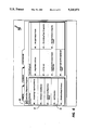
- FIG. 3 is a view depicting an exemplary job programming ticket and job scorecard displayed on the User Interface (UI) touchscreen of the printing system shown in FIG. 1;
- UI User Interface
- FIG. 4 is a view of the UI touchscreen in which the Log-On Sheet for entry into Diagnostics mode is shown;
- FIG. 5 is a view of the UI touchscreen showing the Service Call Procedure sheet obtained on entry into the Diagnostic mode
- FIG. 6 is a view of the UI touchscreen depicting the various Controller Diagnostic Programs including job exerciser available for selection by the Tech Rep;
- FIG. 7 is a view of the UI touchscreen showing the program selections available in the job exerciser program on entry into the Scan & Print mode;
- FIG. 8 is a view of the UI touchscreen showing the program selections available in the job exerciser program on entry into the Print mode;
- FIG. 9 is a view of the UI touchscreen showing the compression ratio test display obtained when the compression ratio test selection is chosen.
- FIGS. 10A and 10B are flow charts depicting the servicing process of the present invention.
- Printing system 2 includes an image input section 4, controller section 7, and printer section 8.
- Image input section 4 has both remote and on-site image inputs, enabling system 2 to provide network, scan, and print services.
- Other system combinations may be envisioned such as a stand alone printing system with on-site image input (i.e., a scanner), controller, and printer; a network printing system with remote input, controller, and printer, etc.
- image input section 4 has a document scanner 10 for the purpose of automatically and sequentially placing and locating sets of multiple documents on a platen 12 for scanning by one or more linear light sensitive arrays 14.
- Array 14 which may utilize Charge-Coupled Device (CCD) technology or the like, provides image elemental signals or pixels representative of the image scanned which are input to processor 18 for processing. Alternately, documents may be located on platen 12 manually for scanning.
- CCD Charge-Coupled Device
- Processor 18 converts the analog image signals output by array 14 to digitally represented facsimile signals and processes the signals as required to enable controller section 7 to store and handle the image in the form and order required to carry out the job programmed. After processing, the image signals are output to controller section 7.
- image input section 4 has a network 5 with a suitable communication channel such as a telephone line enabling image data in the form of image signals or pixels from one or more remote sources to be input to processor 18 for processing.
- a suitable communication channel such as a telephone line
- suitable conversion means are provided.
- Other remote sources of image data such as streaming tape, floppy disk, etc. may be envisioned.
- the image data from processor 18 is compressed by image compressor/processor 20 and placed in an image file which is stored in memory 22 pending use.
- Memory 22 has plural hard disks 24-1, 24-2, 24-3 for this purpose.
- the image data is accessed and output to image output controller 26 where the data is decompressed and readied for printing by printer section 8.
- a User Interface (UI) 29 consisting of a combined operator controller/CRT display provides an interactive touchscreen 30, keyboard 32, and mouse 34.
- UI 29 interfaces the operator with printing system 2, enabling the operator to program print jobs and other instructions, and to obtain system operating information, visual document facsimile display, programming information and icons, diagnostic information and pictorial views, etc.
- Items displayed on touchscreen 30 such as files and icons are actuated by either touching the displayed item on screen 30 with a finger or by using mouse 34 to point a cursor 36 (seen in FIG. 3) to the item selected and keying the mouse.
- Printer section 8 has a laser type printer with a Raster Output Scanner (ROS) 40, Print Module 42, Paper Supply 44, Finisher 46, and Printer System Control 48.
- ROS 40 uses plural laser beams modulated in accordance with the content of an image signal input by acousto-optic modulator to create latent electrostatic images on a photoreceptor. The latent electrostatic images are developed and transferred and fixed to a print media delivered by Paper Supply 44. The finished prints are delivered to either top tray 49 or to finisher 46 which provides certain finishing selections such as a stitching, stapling, etc.
- Printer system control 48 automatically and precisely controls all the printer functions and operations in accordance with job program instructions received from controller section 7.
- printer section 8 may instead use a different printer type such as ink jet, ionographic, thermal, photographic, etc., and furthermore may be incorporated in electronic display systems, such as CRTs, LCDs, LEDs, etc., or else other image scanning/processing/recording systems, or else other signal transmitting/receiving, recording systems, etc. as well.
- printer section 8 may instead use a different printer type such as ink jet, ionographic, thermal, photographic, etc., and furthermore may be incorporated in electronic display systems, such as CRTs, LCDs, LEDs, etc., or else other image scanning/processing/recording systems, or else other signal transmitting/receiving, recording systems, etc. as well.
- jobs are programmed in a Job Program mode in which there is displayed on touchscreen 30 a Job Ticket 50 and a Job Scorecard 52 for the job being programmed.
- Job Ticket 50 displays various print program selections available for programming the test job, while Job Scorecard 52 displays the basic instructions to the system for printing the job.
- Various Job Ticket types are provided, with access by means of Job Types and Tickets icon 54.
- the business location for the printing system 2 referred to herein as the site, is normally secured to prevent unauthorized persons from using or tampering with the system.
- site security is achieved by giving each user a user Identification Number (User ID) 62 and Password 64.
- User ID user Identification Number
- Password Password
- Tech Reps are also users who require access to the system in order to service and repair the system.
- Tech Reps are also assigned a Tech Rep ID number 62 and Tech Rep Password 64.
- the Tech Rep ID number 62 may be a number assigned when printing system 2 is manufactured or when system 2 is installed while the Tech Rep Password 64 may be assigned by the service organization to which the Tech Rep belongs. This protects both the service organization and the site by limiting access to only Tech Reps who have the correct password.
- the Tech Rep password can be changed at any time by the service organization.
- the Tech Rep is barred from accessing or using customer files stored in system 2. This is done to prevent a Tech Rep from altering or erasing customer files, from reading privileged or confidential communications, etc.
- the Tech Rep is permitted to program and run customer type jobs for the limited purpose of servicing the system. The intent is to allow the Tech Rep to program and execute a job while in the Diagnostic Mode without having access to the full operator dialog provided by UI 29.
- the Limited Job Run options or selections provided are a sub-set of the operator dialog job options provided by UI 29. This protects customer files against loss, alteration, etc. by the Tech Rep during the course of servicing the system since the Tech Rep is not able to access, change or alter the customer's files. Additional program choices, which are not available to the ordinary user are also made available to the Tech Rep as will appear.
- a Diagnostic Mode (“Diagnostics") is entered. This mode provides access to various diagnostic routines stored in the system and available to the Tech Rep for use in identifying and correcting system faults. Alternately or in addition, diagnostic routines may be loaded in from exterior sources as by floppy disk, streaming tape, etc.
- a system auxiliary menu icon 70 (seen in FIG. 3) is provided together with a "Diagnostic" selection button 72 on keyboard 32 (seen in FIG. 1).
- auxiliary menu icon 70 On actuation of auxiliary menu icon 70 either by touching icon 70 or by pointing cursor 36 to icon 70 and keying mouse 34, the Log On sheet 60 is displayed on screen 30 with "User ID” and "Password” windows 62, 64. Using Log On sheet 60 and entering the correct user ID number 62 and Password 64, the Tech Rep logs onto the system. With logging on, a special default account is set up against which any jobs run by the Tech Rep during servicing are logged. This enables statistics such as number of prints, finishing selections, etc. to be collected yet does not bill any Tech Rep jobs to a customer's account.
- Selecting "Job Exerciser” 92 displays a "Limited Job Run” job ticket 50-1, 50-2, or 50-3 that provides the Tech Rep with limited print program selections for programming jobs in either a "Scan & Print” mode, or a "Print” mode, or “Compression Ratio Test” mode.
- "Scan & Print”, “Print”, and “Compression Ratio Test” modes are selected by means of "Scan & Print” "Print”, and “Compression Ratio Test” buttons 100, 102, 103 respectively.
- "Scan & Print” mode which has the job ticket 50-1 shown in FIG. 7, and “Compression Ratio Test” mode utilize both scanner and printer sections 4 and 8 respectively while "Print” mode, which has the job ticket 50-2 shown in FIG. 8, utilizes printer section 8 only as will appear.
- Compression ratio test enables the Tech Rep to determine if compressor/processor 20 is satisfactorily compressing the image data for storage on disks 24-1, 24-2, 24-3 of memory 22. Where compressor/processor 20 is not compressing the data at the designed ratio, the amount of data that can be stored on disks 24-1, 24-2, 24-3 is reduced which, in turn, reduces the operating efficiency of the system.
- actuating "Scan & Print” button 100 displays a "Scan & Print” job ticket 50-1 having a series of icons representing the limited number of print program selections available to the Tech Rep in this mode. These include a key pad icon 106 that enables the Tech Rep to program the number of sets to be printed. As will be understood, the number of pages in a set is determined by the number of documents in document handler 10.
- buttons 110-1, 110-2, 110-3, 110-4 for simplex-to-simplex ("1-1"), simplex-to-duplex ("1-2"), duplex-to-simplex ("2-1"), and duplex-to-duplex ("2-2") printing selection;
- "Output Destination” buttons 112-1, 112-2, 112-3, 112-4 for "Top Tray Uncollated”, “Top Tray Collated”, “Stacker Uncollated”, and “Stacker Collated” selections respectively;
- Paper Tray” selection buttons 116-1, 116-2, 116-3 for selecting “Tray 1", “Tray 2” , or “Tray 3" as the paper tray from which the print stock will be supplied;
- "Print Darkness” buttons 118-1 and 118-2 respectively for setting print darkness or lightness levels, and "Scan
- actuating "Print” button 102 displays "Print" job ticket 52-2 with the program selections available to the Tech Rep in the "Print” mode.
- These include key pad 106 for selecting the number of pages per set; "Sides Imaged” buttons 110-1 ("Simplex"), 110-4 ("Duplex”); Output Destination buttons 112-1, 112-2, 112-3, 112-4; "Paper Tray” selection buttons 116-1, 116-2, 116-3; and "Print Darkness” buttons 118-1, 118-2 as described above.
- “Number of Sets” buttons 120-1 and 120-2 enable the number of sets programmed for printing to be increased or decreased respectively.
- "Test Pattern” selection buttons 122-1, 122-2, 122-3, 122-4, 122-5 permit the Tech Rep select registration, solid area, halftone, text, and halftone picture test patterns stored in the system memory 22. "Test Pattern” selections are the type of selection that are not ordinarily available to the normal user or operator of system 2 but instead are for the use of the Tech Rep only.
- actuating "Compression Ratio Test” button 103 displays "Compression Ratio Test” job ticket 50-3 that enables the Tech Rep to identify the current operating compression ratio of compressor/processor 20.
- a standardized document is placed on platen 12, the number of prints desired programmed using keyboard 106 (seen in FIG. 7), and Start/Scan selected. It is necessary for this test that the image size selected matches the document size and the size of the print media in paper supply 44.
- Scanner 10 scans the document on platen 12 while printer section 8 prints the number of prints programmed.
- the compression ratio which is a ratio of input bits to output bits to and from compressor/processor 20, is displayed in window 130. Using this information, the Tech Rep can compare the ratio shown in window 130 with the ratio that should be obtained when processing the standarized document.
- print program selections described above are exemplary only and that different and/or additional selections may be provided. Further, that various test pattern types other than those described may be envisioned as well as various types of documents for testing the compression ratio.
- stop button 124 When the Tech Rep is finished running the test job, stop button 124 is depressed. Actuation of stop button 124 purges the copy of the test job from the system. Since any jobs run by the Tech Rep are charged to the special default account, prints made by the Tech Rep during the course of servicing the system are not billed by the system. At the end of servicing, the special default account is closed.
Abstract
Description
Claims (12)
Priority Applications (1)
| Application Number | Priority Date | Filing Date | Title |
|---|---|---|---|
| US07/766,231 US5210571A (en) | 1991-09-26 | 1991-09-26 | System for servicing electronic printers and printing systems |
Applications Claiming Priority (1)
| Application Number | Priority Date | Filing Date | Title |
|---|---|---|---|
| US07/766,231 US5210571A (en) | 1991-09-26 | 1991-09-26 | System for servicing electronic printers and printing systems |
Publications (1)
| Publication Number | Publication Date |
|---|---|
| US5210571A true US5210571A (en) | 1993-05-11 |
Family
ID=25075804
Family Applications (1)
| Application Number | Title | Priority Date | Filing Date |
|---|---|---|---|
| US07/766,231 Expired - Lifetime US5210571A (en) | 1991-09-26 | 1991-09-26 | System for servicing electronic printers and printing systems |
Country Status (1)
| Country | Link |
|---|---|
| US (1) | US5210571A (en) |
Cited By (20)
| Publication number | Priority date | Publication date | Assignee | Title |
|---|---|---|---|---|
| US5341421A (en) * | 1990-11-06 | 1994-08-23 | Bull Cp8 | Security device, including a memory and/or a microcomputer for data processing machines |
| US5394251A (en) * | 1993-05-21 | 1995-02-28 | Xerox Corporation | Customer schedulable machine quality adjust |
| US5412452A (en) * | 1993-12-20 | 1995-05-02 | Xerox Corporation | Apparatus and method for controlling diagnostic routines concurrently in a printing system |
| US5619307A (en) * | 1994-07-07 | 1997-04-08 | Cannon Kabushiki Kaisha | Method of printing test pattern and apparatus for outputting test pattern |
| US5706103A (en) * | 1994-03-29 | 1998-01-06 | Mitsubishi Denki Kabushiki Kaisha | Image processing device, for use in scanner, printer, digital copying machine and display device |
| US5715487A (en) * | 1996-03-12 | 1998-02-03 | Eastman Kodak Company | Camera and cartridge with password protection |
| US5742406A (en) * | 1991-03-01 | 1998-04-21 | Canon Kabushiki Kaisha | Image processing apparatus |
| US6185379B1 (en) * | 1997-04-30 | 2001-02-06 | Oce Printing Systems Gmbh | Process for operating a high-speed printer or copying machine providing instructions in the event of a failure |
| US6348972B1 (en) * | 1995-06-01 | 2002-02-19 | Tokyo Shibaura Electric Co | Network print system for allowing a printer or printers to select a host |
| US20020120855A1 (en) * | 2001-01-31 | 2002-08-29 | Wiley Anthony J. | Mechanism for controlling if/when material can be printed on a specific printer |
| US6571071B2 (en) * | 2000-09-28 | 2003-05-27 | Ricoh Company, Ltd. | Consumption information management apparatus, image formation apparatus, and consumption information management system |
| US20030135431A1 (en) * | 2001-12-20 | 2003-07-17 | Nexpress Solutions Llc | Linking ORC life tracking/usage with inventory management |
| US6625403B2 (en) | 2001-11-05 | 2003-09-23 | Nexpress Solutions Llc | Personalization of operator replaceable component life prediction based on replaceable component life history |
| US6718285B2 (en) | 2001-11-05 | 2004-04-06 | Nexpress Solutions Llc | Operator replaceable component life tracking system |
| US20040103048A1 (en) * | 2002-11-22 | 2004-05-27 | Nexpress Solutions Llc | Method and apparatus for reducing supply orders in inventory management |
| US20040158745A1 (en) * | 2003-02-07 | 2004-08-12 | Toshiba Tec Kabushiki Kaisha | Digital combined apparatus, control method therefor, and digital combined apparatus system |
| US6778288B1 (en) | 1998-12-07 | 2004-08-17 | Kabushiki Kaisha Toshiba | Image capturing system |
| US20050129245A1 (en) * | 2003-11-13 | 2005-06-16 | Tatsuo Takaoka | Multipurpose key employing network communications apparatus and method |
| US20100138915A1 (en) * | 2008-12-02 | 2010-06-03 | Antonino La Malfa | Password Protected Built-In Test Mode For Memories |
| EP3971650A1 (en) * | 2020-09-18 | 2022-03-23 | Toshiba TEC Kabushiki Kaisha | Image forming apparatus and control method thereof |
Citations (10)
| Publication number | Priority date | Publication date | Assignee | Title |
|---|---|---|---|---|
| US4316720A (en) * | 1979-03-26 | 1982-02-23 | The Singer Company | Maintenance training device |
| US4498132A (en) * | 1981-05-22 | 1985-02-05 | Data General Corporation | Data processing system using object-based information and a protection scheme for determining access rights to such information and using multilevel microcode techniques |
| US4525780A (en) * | 1981-05-22 | 1985-06-25 | Data General Corporation | Data processing system having a memory using object-based information and a protection scheme for determining access rights to such information |
| US4713753A (en) * | 1985-02-21 | 1987-12-15 | Honeywell Inc. | Secure data processing system architecture with format control |
| US4799258A (en) * | 1984-02-13 | 1989-01-17 | National Research Development Corporation | Apparatus and methods for granting access to computers |
| US4937864A (en) * | 1989-04-27 | 1990-06-26 | Xerox Corporation | Debug routine accessing system |
| US5010551A (en) * | 1989-04-14 | 1991-04-23 | Xerox Corporation | Self contained troubleshooting aid for declared and non declared machine problems |
| US5023817A (en) * | 1989-03-06 | 1991-06-11 | Xerox Corporation | Jam history and diagnostics |
| US5077795A (en) * | 1990-09-28 | 1991-12-31 | Xerox Corporation | Security system for electronic printing systems |
| US5127012A (en) * | 1991-02-19 | 1992-06-30 | Eastman Kodak Company | Diagnostic and administrative device for document production apparatus |
-
1991
- 1991-09-26 US US07/766,231 patent/US5210571A/en not_active Expired - Lifetime
Patent Citations (10)
| Publication number | Priority date | Publication date | Assignee | Title |
|---|---|---|---|---|
| US4316720A (en) * | 1979-03-26 | 1982-02-23 | The Singer Company | Maintenance training device |
| US4498132A (en) * | 1981-05-22 | 1985-02-05 | Data General Corporation | Data processing system using object-based information and a protection scheme for determining access rights to such information and using multilevel microcode techniques |
| US4525780A (en) * | 1981-05-22 | 1985-06-25 | Data General Corporation | Data processing system having a memory using object-based information and a protection scheme for determining access rights to such information |
| US4799258A (en) * | 1984-02-13 | 1989-01-17 | National Research Development Corporation | Apparatus and methods for granting access to computers |
| US4713753A (en) * | 1985-02-21 | 1987-12-15 | Honeywell Inc. | Secure data processing system architecture with format control |
| US5023817A (en) * | 1989-03-06 | 1991-06-11 | Xerox Corporation | Jam history and diagnostics |
| US5010551A (en) * | 1989-04-14 | 1991-04-23 | Xerox Corporation | Self contained troubleshooting aid for declared and non declared machine problems |
| US4937864A (en) * | 1989-04-27 | 1990-06-26 | Xerox Corporation | Debug routine accessing system |
| US5077795A (en) * | 1990-09-28 | 1991-12-31 | Xerox Corporation | Security system for electronic printing systems |
| US5127012A (en) * | 1991-02-19 | 1992-06-30 | Eastman Kodak Company | Diagnostic and administrative device for document production apparatus |
Cited By (32)
| Publication number | Priority date | Publication date | Assignee | Title |
|---|---|---|---|---|
| US5341421A (en) * | 1990-11-06 | 1994-08-23 | Bull Cp8 | Security device, including a memory and/or a microcomputer for data processing machines |
| US5742406A (en) * | 1991-03-01 | 1998-04-21 | Canon Kabushiki Kaisha | Image processing apparatus |
| US5394251A (en) * | 1993-05-21 | 1995-02-28 | Xerox Corporation | Customer schedulable machine quality adjust |
| US5412452A (en) * | 1993-12-20 | 1995-05-02 | Xerox Corporation | Apparatus and method for controlling diagnostic routines concurrently in a printing system |
| US5706103A (en) * | 1994-03-29 | 1998-01-06 | Mitsubishi Denki Kabushiki Kaisha | Image processing device, for use in scanner, printer, digital copying machine and display device |
| US5619307A (en) * | 1994-07-07 | 1997-04-08 | Cannon Kabushiki Kaisha | Method of printing test pattern and apparatus for outputting test pattern |
| US6348972B1 (en) * | 1995-06-01 | 2002-02-19 | Tokyo Shibaura Electric Co | Network print system for allowing a printer or printers to select a host |
| US5715487A (en) * | 1996-03-12 | 1998-02-03 | Eastman Kodak Company | Camera and cartridge with password protection |
| US6314249B1 (en) | 1997-04-30 | 2001-11-06 | OCé PRINTING SYSTEMS GMBH | Method for operating a high-performance printer or a copier with assistance given malfunctions |
| US6185379B1 (en) * | 1997-04-30 | 2001-02-06 | Oce Printing Systems Gmbh | Process for operating a high-speed printer or copying machine providing instructions in the event of a failure |
| US6778288B1 (en) | 1998-12-07 | 2004-08-17 | Kabushiki Kaisha Toshiba | Image capturing system |
| US6571071B2 (en) * | 2000-09-28 | 2003-05-27 | Ricoh Company, Ltd. | Consumption information management apparatus, image formation apparatus, and consumption information management system |
| US20020120855A1 (en) * | 2001-01-31 | 2002-08-29 | Wiley Anthony J. | Mechanism for controlling if/when material can be printed on a specific printer |
| US20030154383A9 (en) * | 2001-01-31 | 2003-08-14 | Wiley Anthony J. | Mechanism for controlling if/when material can be printed on a specific printer |
| US7222368B2 (en) * | 2001-01-31 | 2007-05-22 | Hewlett-Packard Development Company, L.P. | Mechanism for controlling if/when material can be printed on a specific printer |
| US6625403B2 (en) | 2001-11-05 | 2003-09-23 | Nexpress Solutions Llc | Personalization of operator replaceable component life prediction based on replaceable component life history |
| US6718285B2 (en) | 2001-11-05 | 2004-04-06 | Nexpress Solutions Llc | Operator replaceable component life tracking system |
| US20030135431A1 (en) * | 2001-12-20 | 2003-07-17 | Nexpress Solutions Llc | Linking ORC life tracking/usage with inventory management |
| US20040103048A1 (en) * | 2002-11-22 | 2004-05-27 | Nexpress Solutions Llc | Method and apparatus for reducing supply orders in inventory management |
| US8024236B2 (en) | 2002-11-22 | 2011-09-20 | Eastman Kodak Company | Method and apparatus for reducing supply orders in inventory management |
| US20110019219A1 (en) * | 2003-02-07 | 2011-01-27 | Kabushiki Kaisha Toshiba | Digital combined apparatus, control method therefor, and digital combined apparatus system |
| US7302580B2 (en) * | 2003-02-07 | 2007-11-27 | Kabushiki Kaisha Toshiba | Digital combined apparatus, control method therefor, and digital combined apparatus system |
| US20080083028A1 (en) * | 2003-02-07 | 2008-04-03 | Kabushiki Kaisha Toshiba | Digital combined apparatus, control method therefor, and digital combined apparatus system |
| US7822991B2 (en) * | 2003-02-07 | 2010-10-26 | Kabushiki Kaisha Toshiba | Digital combined apparatus, control method therefor, and digital combined apparatus system |
| US20040158745A1 (en) * | 2003-02-07 | 2004-08-12 | Toshiba Tec Kabushiki Kaisha | Digital combined apparatus, control method therefor, and digital combined apparatus system |
| US8902438B2 (en) | 2003-02-07 | 2014-12-02 | Kabushiki Kaisha Toshiba | Digital combined apparatus, control method therefor, and digital combined apparatus system |
| US20050129245A1 (en) * | 2003-11-13 | 2005-06-16 | Tatsuo Takaoka | Multipurpose key employing network communications apparatus and method |
| US20100138915A1 (en) * | 2008-12-02 | 2010-06-03 | Antonino La Malfa | Password Protected Built-In Test Mode For Memories |
| US8844023B2 (en) * | 2008-12-02 | 2014-09-23 | Micron Technology, Inc. | Password protected built-in test mode for memories |
| EP3971650A1 (en) * | 2020-09-18 | 2022-03-23 | Toshiba TEC Kabushiki Kaisha | Image forming apparatus and control method thereof |
| US11494138B2 (en) | 2020-09-18 | 2022-11-08 | Toshiba Tec Kabushiki Kaisha | Image forming apparatus and control method thereof including control of print job |
| US11861248B2 (en) | 2020-09-18 | 2024-01-02 | Toshiba Tec Kabushiki Kaisha | Image forming apparatus and control method thereof including control of print job |
Similar Documents
| Publication | Publication Date | Title |
|---|---|---|
| US5210571A (en) | System for servicing electronic printers and printing systems | |
| EP0818724B1 (en) | Security system for electronic printing systems | |
| US6181893B1 (en) | Digital copying apparatus with a personal data storage system | |
| EP0478347B1 (en) | Printing system with automatic statistical compilation and billing | |
| US6778288B1 (en) | Image capturing system | |
| US5694528A (en) | Apparatus and method for diagnosing printing machine operation with facsimile transmitted dialog screens | |
| US6745334B1 (en) | Image forming apparatus and method of controlling same | |
| US8151362B2 (en) | Image forming apparatus, function extending method and user authentication system | |
| JP4198816B2 (en) | Digital image processing device for storing unfinished jobs | |
| US6208436B1 (en) | Use of a header page to provide scan control information for a scan | |
| CN100501759C (en) | Image reading apparatus, image processing system, and image recording apparatus | |
| GB2312131A (en) | Broadcast transmission in a facsimile system | |
| US20050152191A1 (en) | Filing system and method for avoiding filing of identical document data | |
| US5710874A (en) | System for managing printing system memory with machine readable code | |
| US5273434A (en) | System for training technicians for servicing electronic printers and printing systems | |
| EP0529808A2 (en) | Print manager system for electronic job printing | |
| US6463435B1 (en) | Handling of security codes for digital image data files | |
| CN103685811A (en) | Electronic apparatus, display control method and network system | |
| US6903840B1 (en) | Advanced administration functions for copiers and printers on a network | |
| US7222134B1 (en) | Filing system which provides increased availability of image data stored therein | |
| US5936743A (en) | Facsimile control system | |
| EP2540071A1 (en) | Digital image reproduction apparatus and method which can prevent changes to print job settings | |
| US20110222078A1 (en) | Image processing apparatus, operation mode setting method therefor, and recording medium | |
| CN106331425A (en) | Image processing system and image processing apparatus for transmitting image data | |
| JP4155305B2 (en) | Image processing device |
Legal Events
| Date | Code | Title | Description |
|---|---|---|---|
| AS | Assignment |
Owner name: XEROX CORPORATION A CORP. OF NEW YORK, CONNECTI Free format text: ASSIGNMENT OF ASSIGNORS INTEREST.;ASSIGNORS:PELOQUIN, BRAD D.;RENO, JAMES R.;DAHLBY, KAREN L.;REEL/FRAME:005862/0116;SIGNING DATES FROM 19910920 TO 19910925 |
|
| STCF | Information on status: patent grant |
Free format text: PATENTED CASE |
|
| FEPP | Fee payment procedure |
Free format text: PAYOR NUMBER ASSIGNED (ORIGINAL EVENT CODE: ASPN); ENTITY STATUS OF PATENT OWNER: LARGE ENTITY |
|
| FPAY | Fee payment |
Year of fee payment: 4 |
|
| FPAY | Fee payment |
Year of fee payment: 8 |
|
| AS | Assignment |
Owner name: BANK ONE, NA, AS ADMINISTRATIVE AGENT, ILLINOIS Free format text: SECURITY INTEREST;ASSIGNOR:XEROX CORPORATION;REEL/FRAME:013153/0001 Effective date: 20020621 |
|
| AS | Assignment |
Owner name: JPMORGAN CHASE BANK, AS COLLATERAL AGENT, TEXAS Free format text: SECURITY AGREEMENT;ASSIGNOR:XEROX CORPORATION;REEL/FRAME:015134/0476 Effective date: 20030625 Owner name: JPMORGAN CHASE BANK, AS COLLATERAL AGENT,TEXAS Free format text: SECURITY AGREEMENT;ASSIGNOR:XEROX CORPORATION;REEL/FRAME:015134/0476 Effective date: 20030625 |
|
| FPAY | Fee payment |
Year of fee payment: 12 |
|
| AS | Assignment |
Owner name: XEROX CORPORATION, CONNECTICUT Free format text: RELEASE BY SECURED PARTY;ASSIGNOR:JPMORGAN CHASE BANK, N.A. AS SUCCESSOR-IN-INTEREST ADMINISTRATIVE AGENT AND COLLATERAL AGENT TO JPMORGAN CHASE BANK;REEL/FRAME:066728/0193 Effective date: 20220822 |