US5213112A - Tension meter for orthopedic surgery - Google Patents
Tension meter for orthopedic surgery Download PDFInfo
- Publication number
- US5213112A US5213112A US07/827,308 US82730892A US5213112A US 5213112 A US5213112 A US 5213112A US 82730892 A US82730892 A US 82730892A US 5213112 A US5213112 A US 5213112A
- Authority
- US
- United States
- Prior art keywords
- torque
- arm
- tension meter
- tension
- movable arm
- Prior art date
- Legal status (The legal status is an assumption and is not a legal conclusion. Google has not performed a legal analysis and makes no representation as to the accuracy of the status listed.)
- Expired - Lifetime
Links
- 230000000399 orthopedic effect Effects 0.000 title claims description 12
- 238000001356 surgical procedure Methods 0.000 title claims description 12
- 210000000988 bone and bone Anatomy 0.000 claims abstract description 35
- 238000006073 displacement reaction Methods 0.000 claims abstract description 4
- 210000003041 ligament Anatomy 0.000 claims description 26
- 210000002303 tibia Anatomy 0.000 description 24
- 210000000689 upper leg Anatomy 0.000 description 22
- 210000000629 knee joint Anatomy 0.000 description 17
- 230000007246 mechanism Effects 0.000 description 10
- 125000006850 spacer group Chemical group 0.000 description 6
- 238000005259 measurement Methods 0.000 description 5
- 238000006467 substitution reaction Methods 0.000 description 5
- 238000002513 implantation Methods 0.000 description 4
- 238000007796 conventional method Methods 0.000 description 3
- 230000006870 function Effects 0.000 description 3
- 239000000463 material Substances 0.000 description 3
- 238000000034 method Methods 0.000 description 3
- 210000004394 hip joint Anatomy 0.000 description 2
- 210000002414 leg Anatomy 0.000 description 2
- 238000009825 accumulation Methods 0.000 description 1
- 239000000919 ceramic Substances 0.000 description 1
- 238000006243 chemical reaction Methods 0.000 description 1
- 230000008602 contraction Effects 0.000 description 1
- 230000001419 dependent effect Effects 0.000 description 1
- 239000007943 implant Substances 0.000 description 1
- 238000003780 insertion Methods 0.000 description 1
- 230000037431 insertion Effects 0.000 description 1
- 230000008407 joint function Effects 0.000 description 1
- 210000003127 knee Anatomy 0.000 description 1
- 238000012986 modification Methods 0.000 description 1
- 230000004048 modification Effects 0.000 description 1
- 230000008447 perception Effects 0.000 description 1
- 230000000246 remedial effect Effects 0.000 description 1
Images


Classifications
-
- A—HUMAN NECESSITIES
- A61—MEDICAL OR VETERINARY SCIENCE; HYGIENE
- A61B—DIAGNOSIS; SURGERY; IDENTIFICATION
- A61B17/00—Surgical instruments, devices or methods, e.g. tourniquets
- A61B17/02—Surgical instruments, devices or methods, e.g. tourniquets for holding wounds open; Tractors
- A61B17/025—Joint distractors
-
- A—HUMAN NECESSITIES
- A61—MEDICAL OR VETERINARY SCIENCE; HYGIENE
- A61B—DIAGNOSIS; SURGERY; IDENTIFICATION
- A61B90/00—Instruments, implements or accessories specially adapted for surgery or diagnosis and not covered by any of the groups A61B1/00 - A61B50/00, e.g. for luxation treatment or for protecting wound edges
- A61B90/06—Measuring instruments not otherwise provided for
-
- A—HUMAN NECESSITIES
- A61—MEDICAL OR VETERINARY SCIENCE; HYGIENE
- A61F—FILTERS IMPLANTABLE INTO BLOOD VESSELS; PROSTHESES; DEVICES PROVIDING PATENCY TO, OR PREVENTING COLLAPSING OF, TUBULAR STRUCTURES OF THE BODY, e.g. STENTS; ORTHOPAEDIC, NURSING OR CONTRACEPTIVE DEVICES; FOMENTATION; TREATMENT OR PROTECTION OF EYES OR EARS; BANDAGES, DRESSINGS OR ABSORBENT PADS; FIRST-AID KITS
- A61F2/00—Filters implantable into blood vessels; Prostheses, i.e. artificial substitutes or replacements for parts of the body; Appliances for connecting them with the body; Devices providing patency to, or preventing collapsing of, tubular structures of the body, e.g. stents
- A61F2/02—Prostheses implantable into the body
- A61F2/30—Joints
- A61F2/46—Special tools or methods for implanting or extracting artificial joints, accessories, bone grafts or substitutes, or particular adaptations therefor
- A61F2/4657—Measuring instruments used for implanting artificial joints
-
- A—HUMAN NECESSITIES
- A61—MEDICAL OR VETERINARY SCIENCE; HYGIENE
- A61B—DIAGNOSIS; SURGERY; IDENTIFICATION
- A61B17/00—Surgical instruments, devices or methods, e.g. tourniquets
- A61B17/02—Surgical instruments, devices or methods, e.g. tourniquets for holding wounds open; Tractors
- A61B17/025—Joint distractors
- A61B2017/0268—Joint distractors for the knee
-
- A—HUMAN NECESSITIES
- A61—MEDICAL OR VETERINARY SCIENCE; HYGIENE
- A61B—DIAGNOSIS; SURGERY; IDENTIFICATION
- A61B90/00—Instruments, implements or accessories specially adapted for surgery or diagnosis and not covered by any of the groups A61B1/00 - A61B50/00, e.g. for luxation treatment or for protecting wound edges
- A61B90/03—Automatic limiting or abutting means, e.g. for safety
- A61B2090/031—Automatic limiting or abutting means, e.g. for safety torque limiting
-
- A—HUMAN NECESSITIES
- A61—MEDICAL OR VETERINARY SCIENCE; HYGIENE
- A61B—DIAGNOSIS; SURGERY; IDENTIFICATION
- A61B90/00—Instruments, implements or accessories specially adapted for surgery or diagnosis and not covered by any of the groups A61B1/00 - A61B50/00, e.g. for luxation treatment or for protecting wound edges
- A61B90/06—Measuring instruments not otherwise provided for
- A61B2090/064—Measuring instruments not otherwise provided for for measuring force, pressure or mechanical tension
-
- A—HUMAN NECESSITIES
- A61—MEDICAL OR VETERINARY SCIENCE; HYGIENE
- A61F—FILTERS IMPLANTABLE INTO BLOOD VESSELS; PROSTHESES; DEVICES PROVIDING PATENCY TO, OR PREVENTING COLLAPSING OF, TUBULAR STRUCTURES OF THE BODY, e.g. STENTS; ORTHOPAEDIC, NURSING OR CONTRACEPTIVE DEVICES; FOMENTATION; TREATMENT OR PROTECTION OF EYES OR EARS; BANDAGES, DRESSINGS OR ABSORBENT PADS; FIRST-AID KITS
- A61F2/00—Filters implantable into blood vessels; Prostheses, i.e. artificial substitutes or replacements for parts of the body; Appliances for connecting them with the body; Devices providing patency to, or preventing collapsing of, tubular structures of the body, e.g. stents
- A61F2/02—Prostheses implantable into the body
- A61F2/30—Joints
- A61F2/32—Joints for the hip
-
- A—HUMAN NECESSITIES
- A61—MEDICAL OR VETERINARY SCIENCE; HYGIENE
- A61F—FILTERS IMPLANTABLE INTO BLOOD VESSELS; PROSTHESES; DEVICES PROVIDING PATENCY TO, OR PREVENTING COLLAPSING OF, TUBULAR STRUCTURES OF THE BODY, e.g. STENTS; ORTHOPAEDIC, NURSING OR CONTRACEPTIVE DEVICES; FOMENTATION; TREATMENT OR PROTECTION OF EYES OR EARS; BANDAGES, DRESSINGS OR ABSORBENT PADS; FIRST-AID KITS
- A61F2/00—Filters implantable into blood vessels; Prostheses, i.e. artificial substitutes or replacements for parts of the body; Appliances for connecting them with the body; Devices providing patency to, or preventing collapsing of, tubular structures of the body, e.g. stents
- A61F2/02—Prostheses implantable into the body
- A61F2/30—Joints
- A61F2/38—Joints for elbows or knees
-
- A—HUMAN NECESSITIES
- A61—MEDICAL OR VETERINARY SCIENCE; HYGIENE
- A61F—FILTERS IMPLANTABLE INTO BLOOD VESSELS; PROSTHESES; DEVICES PROVIDING PATENCY TO, OR PREVENTING COLLAPSING OF, TUBULAR STRUCTURES OF THE BODY, e.g. STENTS; ORTHOPAEDIC, NURSING OR CONTRACEPTIVE DEVICES; FOMENTATION; TREATMENT OR PROTECTION OF EYES OR EARS; BANDAGES, DRESSINGS OR ABSORBENT PADS; FIRST-AID KITS
- A61F2/00—Filters implantable into blood vessels; Prostheses, i.e. artificial substitutes or replacements for parts of the body; Appliances for connecting them with the body; Devices providing patency to, or preventing collapsing of, tubular structures of the body, e.g. stents
- A61F2/02—Prostheses implantable into the body
- A61F2/30—Joints
- A61F2/44—Joints for the spine, e.g. vertebrae, spinal discs
- A61F2/442—Intervertebral or spinal discs, e.g. resilient
-
- A—HUMAN NECESSITIES
- A61—MEDICAL OR VETERINARY SCIENCE; HYGIENE
- A61F—FILTERS IMPLANTABLE INTO BLOOD VESSELS; PROSTHESES; DEVICES PROVIDING PATENCY TO, OR PREVENTING COLLAPSING OF, TUBULAR STRUCTURES OF THE BODY, e.g. STENTS; ORTHOPAEDIC, NURSING OR CONTRACEPTIVE DEVICES; FOMENTATION; TREATMENT OR PROTECTION OF EYES OR EARS; BANDAGES, DRESSINGS OR ABSORBENT PADS; FIRST-AID KITS
- A61F2/00—Filters implantable into blood vessels; Prostheses, i.e. artificial substitutes or replacements for parts of the body; Appliances for connecting them with the body; Devices providing patency to, or preventing collapsing of, tubular structures of the body, e.g. stents
- A61F2/02—Prostheses implantable into the body
- A61F2/30—Joints
- A61F2/46—Special tools or methods for implanting or extracting artificial joints, accessories, bone grafts or substitutes, or particular adaptations therefor
- A61F2/4657—Measuring instruments used for implanting artificial joints
- A61F2002/4666—Measuring instruments used for implanting artificial joints for measuring force, pressure or mechanical tension
Definitions
- This invention relates to a tension meter for orthopedic surgery for expanding a spacing between bones and measuring a degree of tension between the bones before embedding an artificial joint or implanting an artificial bone between the bones.
- Such an artificial joint or an artificial bone is surgically embedded or implanted into a human body.
- a spacing between bones in the knee joint is set before actually embedding the artificial joint.
- a distal portion of a femur and a proximal portion of a tibia are first cut away, and then a spacer having a suitable thickness is inserted into the spacing between the femur and the tibia.
- a surgeon checks the degree of tension of the ligaments connecting the femur and the tibia at opposite side portions of the knee joint by touching the ligaments with his fingers.
- the surgeon measures the degree of tension of the ligaments with his senses by swinging a leg portion below the tibia in right, left, front and rear directions.
- the tensile strength of the ligaments is individually dependent on patients, it is necessary to expand the spacing between the femur and the tibia to a suitable value according to the tensile strength of each patient and stretch the ligaments under a suitable tension, so as to make the artificial joint function properly.
- various spacers are provided having different thicknesses are used in succession to select an optimum one of these spacers and set the spacing between the femur and the tibia according to the tensile strength of PG,3 the ligaments of the patient. Thereafter, the selected spacer is removed from the knee joint, and an artificial joint having a size corresponding to the spacing set above is then embedded into the knee joint.
- This invention has been achieved in view of the above circumstances, and it is an object of the present invention to provide a tension meter which can measure a degree of tension between bones according to quantitative data and makes it possible to carry out a surgical operation with high reproducibility according to this data.
- the tension meter for orthopedic surgery for expanding the between two bones and measuring a degree of tension between the bones before embedding an artificial joint or implanting a prosthetic implant therebetween.
- the tension meter comprises a grip portion, a tension meter body mounted to the grip portion, and a torque setting device rotatably connected through a torque shaft to the tension meter body.
- the tension meter body comprises a body portion, a fixed arm extending from one end of the body portion on the opposite side of said grip portion.
- a movable arm is mounted on an upper surface of the body portion so as to be movable away therefrom. The movable arm being located just above said fixed arm in opposed relationship thereto.
- a degree of tension of a ligament can be preliminarily set by the torque limiter mechanism on the basis of past data or the like. Accordingly, a spacing between bones can be expanded properly and quantitatively by the fixed arm and the movable arm without reliance upon surgeon's senses as in the prior art.
- FIG. 3 is a perspective view showing the use of the tension meter shown in FIG. 1 for the substitution of an artificial joint for a knee joint;
- FIG. 4 is a side view showing the use of the tension meter according to the present invention for the implantation of an artificial bone for fixing a vertebral body;
- FIG. 5 is a side view showing the use of the tension meter according to the present invention for the substitution of an artificial joint for a hip joint;
- FIG. 6 is a perspective view explaining a conventional method of a surgical operation in the case of substituting an artifical joint for a knee joint;
- FIG. 7 is a perspective view explaining another conventional method of the surgical operation in the case of substituting an artificial joint for a knee joint.
- FIG. 8 is a side view explaining a further conventional method of the surgical operation in the case of implanting an artifical bone between vertebral bodies.
- FIGS. 6 and 7 there is shown known expanders 4 which have been employed to tension the joint.
- Spacers 3 of varying thicknesses have been used to set the gap between femur 1 and tibia 2 according to the tension in the ligaments.
- selected spacer 3 is removed and a prosthetic knee joint having a size corresponding to the opening is implanted.
- the expander 4 is provided with a pair of upper arms 5 and a pair of lower arms 6 connected therewith by means of a pair of screws 7.
- the opening between upper arms 5 and the lower arms 6 is adjusted by adjusting the degree of tightness of screws 7.
- a degree of tension between the femur 1 and tibia 2 is checked in the following manner.
- upper arms 5 and lower arms 6 are closed (in contact) and are inserted between femur 1 and tibia 2. Then the opening between arms 5 and the lower arms 6 is then expanded by rotating screws 7. During this operation, the surgeon finds a degree of proper tension of the ligaments with his perception or senses based on his experience as sensing a stress applied to his fingers during rotation of screws 7, thus setting a suitable spacing between the femur 1 and tibia 2. Thereafter, expander 4 is removed from the knee joint, a distance of the spacing between upper arms 5 and lower arms 6 is measured, and an artificial joint having a size corresponding to this distance is selected. Then the selected artificial joint is embedded between femur 1 and tibia 2.
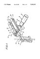
- reference numeral 10 generally designates a tension meter of the present invention for use in orthopedic surgery (which will be hereinafter be referred to as a tension meter).
- Tension meter 10 is primarily used to measure the degree of tension between a femur 1 and a tibia 2 before implanting an artificial knee joint.
- tension meter 10 is generally constructed of a grip portion 11, a tension meter body 12 mounted to the grip portion 11, and a torque setting device 14 rotatably connected through a torque shaft 13 to the tension meter body 12.
- Grip portion 11 is formed like a pistol grip, and it is adapted to be gripped by a hand to thereby support tension meter 10 as a whole.
- Grip portion 11 is formed with a vertical through-hole 16 for inserting a vertical positioning rod 15 and supporting the same.
- Rod 15 is used for positioning tension meter 10 in such a manner that rod 15 is vertically erected through hole 16 of grip portion 11, and is then made parallel to tibia 2 to thereby make perpendicular to the tibia 2 a longitudinal direction of movable arms 26 and fixed arms 19 which will be hereinafter described.
- Tension meter body 12 is integrally connected through a connecting rod 17 to an upper front end of grip portion 11.
- Tension meter body 12 is comprised of a rectangular parallelepiped block portion or body portion 18, a pair of fixed arms 19 extending frontwardly from the block portion 18, and a positioning portion 20 formed at a central portion of an upper surface of the block portion 18.
- the fixed arms 19 extend to the opposite side of the grip portion 11, and each of fixed arms 19 has an arcuate front end.
- Fixed arms 19 are adapted to be inserted between femur 1 and tibia 2 so as to be positioned on the tibia 2 side.
- Fixed arms 19 are arranged in suitably spaced relationship from each other so as to correspond to two ligaments connecting opposite side portions of femur 1 and tibia 2 with each other, so that when they are inserted between femur 1 and tibia 2, they are prevented from being deflected.
- Positioning portion 20 projects from the upper surface of block portion 18 at the transversely central position thereof, and extends from grip portion 11 side to the fixed arms 19 side.
- a semi-cylindrical mounting member 21 is detachably mounted on a rear end portion of positioning portion 20.
- Mounting member 21 is formed at its central portion with a through-hole 22 extending in a longitudinal direction of positioning portion 20.
- a horizontal positioning rod 23 is adapted to be inserted through through-hole 22 of mounting member 21. Rod 23 functions similarly to rod 15.
- rod 23 is used for positioning the tension meter 10 in such a manner that rod 23 is inserted through hole 22 of mounting member 21 so as to be made parallel to positioning portion 20, and tension meter 10 is adjusted in position so as to be made parallel to femur 1 under a normally bent condition of a knee, thereby making the longitudinal direction of fixed arms 19 parallel to femur 1.
- block portion 18 which is formed with a pair of vertical through-holes 23' on the right and left sides of positioning portion 20 and a pair of vertical through-holes 24 on the right and left sides of the positioning portion 20. That is, through-holes 23' formed on fixed arms 19 side are arranged in parallel to through-holes 24 formed on grip portion 11 side. As will be hereinafter described, through-holes 23' are formed to receive a pair of rack gears 27, and through-holes 24 are formed to receive a pair of supporting rods 28. Further, block portion 18 is formed on its one side surface with a horizontal hole 25 for receiving the torque shaft 13. Hole 25 is communicated with through-holes 23 in block portion or body portion 18, so that torque shaft 13 can mesh with rack gears 27 in block portion 18.
- a pair of movable arms 26 are provided on the upper surface of block portion 18 so as to be movable away therefrom.
- Movable arms 26 are formed as substantially rectangular elongated plate-like members, and they are disposed just above fixed arms 19, respectively.
- each of movable arms 26 has an arcuate front end.
- Each rack gear 27 and each supporting rod 28 project downwardly from a lower surface of each movable arm 26.
- Each rack gear 27 has a gear portion directed to grip portion 11 side, and is movably inserted into corresponding through-hole 23 of block portion 18.
- Each supporting rod 28 formed as a round rod is arranged on the rear side of each rack gear 27, and is movably inserted into corresponding through-hole 24 of the block portion 18.
- both movable arms 26 are mounted on the upper surface of block portion 18 so as to be movable away therefrom by movably inserting rack gears 27 into through-holes 23' and movably inserting supporting rods 28 into the through-holes 24.
- An outer diameter of each supporting rod 28 is set to be slightly smaller than an inner diameter of each through-hole 24, so that when the movable arms are inclined by a load applied to the front ends of movable arms 26, movable arms 26 cannot be vertically moved.
- Torque shaft 13 is rotatably inserted in hole 25 of block portion 18.
- Torque shaft 13 is comprised of a small-diameter round rod portion and a large-diameter portion 30 formed at a rear end of the small diameter portion.
- the small diameter portion of torque shaft 13 is formed with front and rear pinion portions 29 adapted to mesh with rack gears 27 of the movable arms 26 under the condition where torque shaft 13 is inserted in hole 25.
- Large diameter portion 30 of torque shaft 13 has an outer diameter larger than an inner diameter of hole 25. Accordingly, when torque shaft 13 is rotated in hole 25, movable arms 26 are vertically moved above block portion 18 by a pair of rack-and-pinion mechanisms formed by pinion portions 29 and rack gears 27.
- the connecting hole 31 has a square opening for receiving a connecting shaft 32 having a square cross-section which will be hereinafter described.
- torque setting device 14 is detachably mounted to the torque shaft 13.
- torque setting devices are well known and may be purchased from Tohnichi Corp. in Japan as their RTD series torque setting devices.
- Torque setting device 14 is comprised of the rectangular prismatic connecting shaft 32 adapted to be fitted with the connecting hole 31 of the torque shaft 13, a columnar set load dial portion 33 incorporating a rear end portion of the connecting shaft 32, and a columnar adjusting portion 34 rotatably connected to set load dial portion 33.
- torque setting device 14 includes a torque limiter mechanism constructed by a known technique. That is, the torque limiter mechanism functions to limit a torque to be transmitted to connecting shaft 32 to a value less than an adjusted biasing force of a spring incorporated in the torque setting device 14.
- a load is set by rotating adjusting portion 34 relative to the set load dial portion 33 prior to engagement of connecting rod 32 into connecting hole 31, and making a position of the front end surface of adjusting portion 34 accord with a desired dial of the set load dial portion 33.
- the biasing force of the spring incorporated in torque setting device 14 is adjusted to a value corresponding to the above set load by the rotation of adjusting portion 34 relative to the set load dial portion 33.
- the connecting rod 32 is brought into engagement with the connecting hole 31, and the adjusting portion 34 is further rotated to rotate torque shaft 13 through connecting rod 32.
- an artificial joint is substituted for a knee joint in the following manner.
- adjusting portion 34 is rotated relative to the set load dial portion 33 to set a torque value corresponding to a degree of tension of the ligaments of a patient according to a strength of the ligaments on the basis of past data or the like.
- connecting rod 32 is inserted into the connecting hole 31 of torque shaft 13.
- movable arms 26 are maintained in contact with upper surface of block portion 18. That is, no gap is present between the movable arms 26 and the fixed arms 19. Further, rack gears 27 of movable arms 26 are meshed with pinion portions 29 of torque shaft 13.
- the surgeon After the opening between femur 1 and tibia 2 is expanded so as to obtain the preliminarily set load value (i.e., a value converted from a degree of tension of the ligaments or a value converted from a distance of the opening or gap between femur 1 and tibia 2; and which set value corresponds to the degree of tension or the distance), the surgeon checks whether or not a stretch condition of the ligaments is optimum by touching the ligaments with his/her fingers or swinging a leg portion below the joint in right, left, front and rear directions.
- the preliminarily set load value i.e., a value converted from a degree of tension of the ligaments or a value converted from a distance of the opening or gap between femur 1 and tibia 2; and which set value corresponds to the degree of tension or the distance
- the above operation is repeated, that is the gap between femur 1 and tibia 2 is expanded so as to correspond to the preliminarily set load value by lifting the movable arms 26.
- the spacing between movable arms 26 and fixed arms 19 at this time is measured. Then, an artificial joint having a size corresponding to this measured spacing is selected and then implanted.
- the degree of tension of the ligaments can be adjusted to a value set by the torque limiter mechanism on the basis of past data or the like. Accordingly, unlike the prior art such that an artificial joint is selected merely by surgeon's senses, the present invention can make it possible to select an artificial joint quantitatively or more precisely. Furthermore, since the quantitative data is recorded, a highly reproducible surgical operation can be carried out based on accumulated data.
- FIG. 4 shows a second preferred embodiment of the present invention in which the tension meter for orthopedic surgery is used for implanting an artificial bone to fix a vertebral body.
- a tension meter 35 instead of the conventional spreader 8 shown in FIG. 8, an artificial bone can be implanted quantitatively or precisely without the reliance upon surgeon's senses, and a highly reproducible surgical operation can be carried out in the same manner as in the first preferred embodiment using the tension meter 10 shown in FIGS. 1-3.
- tension meter 35 to be used for fixation of a vertebral body does not require a pair of movable arms and a pair of fixed arms, but only requires a single movable arm and a single fixed arm.
- a single movable arm and a single fixed arm are provided when replacing a knee joint, it is difficult to uniformly stretch the ligaments connecting the opposite side portions of the femur and the tibia upon insertion of the single movable arm and the single fixed arm into the opening between both the bones for expanding the gap. Therefore, it is preferable to provide a pair of movable arms and a pair of fixed arms when using the tension meter in replacing a knee joint with a prosthesis.
- a sufficient balance can be obtained upon expansion of a spacing between the vertebral bodies 9 by using a single movable arm and a single fixed arm.
- an intervertebral disk present at an implantation position is first cut away prior to implantation of the artificial bone. Then a front end portion of a spreader 8 (as shown in FIG. 8) is inserted between adjacent vertebral bodies 9, and the opening therebetween is spread by using the spreader 8. Then, the artificial bone is implanted into this opening.
- a degree of spreading of the opening between the vertebral bodies 9 relies on X-ray measurement carried out before the surgical operation or macroscopic measurement of a distance between the vertebral bodies 9 during the surgical operation.
- the tension meter for orthopedic surgery in the above preferred embodiments is applied to the substitution of an artificial joint for a knee joint and the implantation of an artificial bone for fixing a vertebral body
- the present invention may be applied to the substitution of an artificial joint for a hip joint, for example, as shown in FIG. 5.
- a degree of tension of a ligament can be preliminarily set by the torque limiter mechanism on the basis of past data or the like. Accordingly, the space between bones can be expanded properly and quantitatively by the fixed arm and the movable arm without the reliance upon surgeon's senses as in the prior art. As a result, an artificial joint or an artificial bone can be precisely selected. Furthermore, since quantitative data is left, a surgical operation with high reproducibility can be carried out owing to accumulation of the data, thereby expediting the surgical operation and increasing the reliability of the surgical operation
Abstract
Description
Claims (8)
Priority Applications (1)
| Application Number | Priority Date | Filing Date | Title |
|---|---|---|---|
| US07/827,308 US5213112A (en) | 1992-01-29 | 1992-01-29 | Tension meter for orthopedic surgery |
Applications Claiming Priority (1)
| Application Number | Priority Date | Filing Date | Title |
|---|---|---|---|
| US07/827,308 US5213112A (en) | 1992-01-29 | 1992-01-29 | Tension meter for orthopedic surgery |
Publications (1)
| Publication Number | Publication Date |
|---|---|
| US5213112A true US5213112A (en) | 1993-05-25 |
Family
ID=25248882
Family Applications (1)
| Application Number | Title | Priority Date | Filing Date |
|---|---|---|---|
| US07/827,308 Expired - Lifetime US5213112A (en) | 1992-01-29 | 1992-01-29 | Tension meter for orthopedic surgery |
Country Status (1)
| Country | Link |
|---|---|
| US (1) | US5213112A (en) |
Cited By (128)
| Publication number | Priority date | Publication date | Assignee | Title |
|---|---|---|---|---|
| US5431653A (en) * | 1993-07-06 | 1995-07-11 | Callaway; George H. | Knee joint flexion-gap distraction device |
| EP0676176A1 (en) * | 1994-03-16 | 1995-10-11 | United States Surgical Corporation | Surgical instruments useful for endoscopic spinal procedures |
| EP0681811A2 (en) * | 1994-03-16 | 1995-11-15 | United States Surgical Corporation | Surgical instruments useful for endoscopic spinal procedures |
| FR2719763A1 (en) * | 1994-05-11 | 1995-11-17 | Jean Taylor | Vertebral implant. |
| US5468244A (en) * | 1991-11-06 | 1995-11-21 | Howmedica International, Inc. | Surgical apparatus for use in joint replacement surgery |
| WO1996017552A1 (en) * | 1994-12-05 | 1996-06-13 | Intermedics Orthopedics, Inc. | Knee distractor device |
| US5540696A (en) * | 1995-01-06 | 1996-07-30 | Zimmer, Inc. | Instrumentation for use in orthopaedic surgery |
| EP0754439A2 (en) * | 1995-07-05 | 1997-01-22 | Michael J. Pappas | Spacer for establishing prosthetic gap and ligamentous tension |
| US5601565A (en) * | 1995-06-02 | 1997-02-11 | Huebner; Randall J. | Osteotomy method and apparatus |
| US5616147A (en) * | 1992-11-26 | 1997-04-01 | Meduse Scandinavia Ab | Means to safely determine the mutual positions of a femur and an ilium in hip surgery |
| US5649929A (en) * | 1995-07-10 | 1997-07-22 | Callaway; George Hadley | Knee joint flexion-gap distraction device |
| US5688282A (en) * | 1995-08-24 | 1997-11-18 | Benois & Girard & Cie | Distraction apparatus for a knee |
| EP0809969A2 (en) * | 1996-05-28 | 1997-12-03 | Howmedica International Inc. | Bone cutting guide |
| US5733292A (en) * | 1995-09-15 | 1998-03-31 | Midwest Orthopaedic Research Foundation | Arthroplasty trial prosthesis alignment devices and associated methods |
| US5791350A (en) * | 1995-06-07 | 1998-08-11 | Morton; John Y. | Device and method for measuring force systems |
| US5800438A (en) * | 1995-10-23 | 1998-09-01 | Finsbury (Instruments) Limited | Surgical tool |
| US5860980A (en) * | 1997-09-15 | 1999-01-19 | Axelson, Jr.; Stuart L. | Surgical apparatus for use in total knee arthroplasty and surgical methods for using said apparatus |
| US5925049A (en) * | 1996-02-23 | 1999-07-20 | Midwest Orthopedic Research Foundation | Device and method for distal femur cutting and prosthesis measuring |
| US5980473A (en) * | 1997-04-08 | 1999-11-09 | Barnes-Jewish Hospital | Surgical apparatus for determining ligament and tendon tension |
| WO2000019911A3 (en) * | 1998-10-02 | 2000-07-13 | Synthes Ag | Spinal disc space distractor |
| WO2000078225A1 (en) * | 1999-06-19 | 2000-12-28 | Mathys Medizinaltechnik Ag | Ligament-tensioning device for non-spheroid joints |
| WO2001085033A2 (en) * | 2000-05-05 | 2001-11-15 | Osteotech, Inc. | Intervertebral distractor and implant insertion instrument |
| US20020133164A1 (en) * | 2000-06-29 | 2002-09-19 | Williamson Richard V. | Instruments and methods for use in performing knee surgery |
| US6468232B1 (en) * | 2000-07-13 | 2002-10-22 | The Regents Of The University Of Michigan | Method and apparatus for measuring properties of the pelvic floor muscles |
| US20030055503A1 (en) * | 2001-09-19 | 2003-03-20 | O'neil Michael J. | Alignment verification device and method of use |
| EP1304093A1 (en) * | 2001-10-22 | 2003-04-23 | Sofinordest, S.A.S. | Method for measuring the balance of ligaments and ancillary for preparing the implantation of a knee prosthesis |
| US6632225B2 (en) * | 2001-06-20 | 2003-10-14 | Zimmer, Inc. | Method and apparatus for resecting a distal femur and a proximal tibia in preparation for implanting a partial knee prosthesis |
| US20030225416A1 (en) * | 2002-05-21 | 2003-12-04 | Bonvallet Todd C. | Instruments and techniques for separating bony structures |
| US20030236472A1 (en) * | 2002-06-19 | 2003-12-25 | James Van Hoeck | Systems and methods for moving anatomical elements |
| WO2004004576A1 (en) * | 2002-07-05 | 2004-01-15 | Mathys Medizinaltechnik Ag | Ligament tensing device with displaceable lug |
| US20040044297A1 (en) * | 2002-08-29 | 2004-03-04 | Kirkpatrick Lynn A. | Ligament tension gauge |
| US20040059262A1 (en) * | 2002-09-20 | 2004-03-25 | Alexander Grinberg | Spreader tensiometer for measuring tension in an intervertebral disc space |
| US20040059261A1 (en) * | 2002-09-20 | 2004-03-25 | Alexander Grinberg | Pivoted tensiometer for measuring tension in an intervertebral disc space |
| EP1402857A2 (en) * | 2002-09-30 | 2004-03-31 | Depuy Products, Inc. | System for tension assessment during joint arthroplasty |
| WO2004034904A1 (en) * | 2002-10-21 | 2004-04-29 | Poul Torben Nielsen | Measuring equipment for use in connection with hip prosthesis surgery |
| US20040097951A1 (en) * | 2002-11-18 | 2004-05-20 | Steffensmeier Scott J. | Measurement instrument for use in orthopaedic surgery |
| US20040117019A1 (en) * | 2000-08-30 | 2004-06-17 | Trieu Hai H. | Method and apparatus for delivering an intervertebral disc implant |
| US6755841B2 (en) | 2000-05-08 | 2004-06-29 | Depuy Acromed, Inc. | Medical installation tool |
| DE10255553A1 (en) * | 2002-11-28 | 2004-07-08 | Thomas Dr. Lübbers | Device for correction of spine of person suffering from spondylolisthesis without using bone screws |
| US20040176764A1 (en) * | 2003-03-03 | 2004-09-09 | Centerpulse Spine-Tech, Inc. | Apparatus and method for spinal distraction using a flip-up portal |
| WO2004084741A1 (en) * | 2003-03-27 | 2004-10-07 | Chong-Bum Kim | Determination device for size of cutting block using connection device |
| US20040249385A1 (en) * | 2003-04-25 | 2004-12-09 | Francisco Faoro | Apparatus for the fixing of the position of bone cuts |
| US20040249387A1 (en) * | 2003-04-25 | 2004-12-09 | Francisco Faoro | Apparatus for the preparation of a femoral condyle |
| US20050021044A1 (en) * | 2003-06-09 | 2005-01-27 | Vitruvian Orthopaedics, Llc | Surgical orientation device and method |
| US20050020941A1 (en) * | 2003-07-24 | 2005-01-27 | Samih Tarabichi | Dynamic spacer for total knee arthroplasty |
| US20050027226A1 (en) * | 2003-05-06 | 2005-02-03 | Centerpulse Orthopedics Ltd. | Traction apparatus |
| FR2858547A1 (en) * | 2003-08-05 | 2005-02-11 | Depuy France | Natural or prosthetic knee joint tensioning device for knee arthroplasty, has femoral and tibial inserts with condylar and tibial plate support surfaces, and unit to maintain knee tensioning during joint rotation for different angles |
| US20050059980A1 (en) * | 2003-09-15 | 2005-03-17 | Centerpulse Orthopedics Ltd. | Adjustment apparatus |
| US20050143746A1 (en) * | 2003-12-26 | 2005-06-30 | Steffensmeier Scott J. | Adjustable resection guide |
| US20050190380A1 (en) * | 2004-02-03 | 2005-09-01 | Norman Plassky | Device for determining the position of an incision block |
| US20060025656A1 (en) * | 2004-07-23 | 2006-02-02 | North Carolina State University | Force-determining retraction device and associated method |
| US20060058785A1 (en) * | 2002-03-22 | 2006-03-16 | Ernst Fuchs | Distraction device used for osteogenesis |
| US20060074431A1 (en) * | 2004-09-28 | 2006-04-06 | Depuy Spine, Inc. | Disc distraction instrument and measuring device |
| US20060089653A1 (en) * | 2002-06-28 | 2006-04-27 | Auger Daniel D | Kit, guide and method for locating distal femoral resection plane |
| US20060149287A1 (en) * | 2003-03-11 | 2006-07-06 | Stephane Lavallee | Instrument for fixing the position of a cutting plane |
| US20060149276A1 (en) * | 2002-12-20 | 2006-07-06 | Grimm James E | Surgical instrument and positioning method |
| CZ296843B6 (en) * | 2004-11-29 | 2006-07-12 | Ceské vysoké ucení technické v Praze Fakulta strojní | Proportional strain sensor, particularly bone strain sensor |
| US20060241569A1 (en) * | 2005-03-31 | 2006-10-26 | Disilvestro Mark R | Method and apparatus for use in balancing ligaments of a knee |
| US20060247647A1 (en) * | 2002-11-27 | 2006-11-02 | Zimmer Technology, Inc. | Method and apparatus for achieving correct limb alignment in unicondylar knee arthroplasty |
| US20060243464A1 (en) * | 2005-04-29 | 2006-11-02 | Sdgi Holdings, Inc. | Torque and angular rotation measurement device and method |
| US20060264963A1 (en) * | 2004-10-27 | 2006-11-23 | Peter Reed | Vertebral spreading instrument comprising markers |
| US20060293685A1 (en) * | 2001-04-19 | 2006-12-28 | Kevin T. Stone And Ryan Cameron Lakin | Segmented joint distractor |
| US20070123903A1 (en) * | 2005-10-31 | 2007-05-31 | Depuy Spine, Inc. | Medical Device installation tool and methods of use |
| EP1808133A1 (en) * | 1998-10-02 | 2007-07-18 | Synthes GmbH | Spinal disc space distractor |
| US20070173854A1 (en) * | 2006-01-23 | 2007-07-26 | Berger Richard A | Bone resection apparatus and method for knee surgery |
| US20070185375A1 (en) * | 2006-02-06 | 2007-08-09 | Depuy Spine, Inc. | Medical device installation tool |
| US20070219415A1 (en) * | 2006-03-14 | 2007-09-20 | Heinz Eric S | Interoperative monitoring of intramuscular pressure during retraction |
| US20070244488A1 (en) * | 2006-03-03 | 2007-10-18 | Robert Metzger | Tensor for use in surgical navigation |
| US7338499B1 (en) | 2004-09-13 | 2008-03-04 | Howmedia Osteonics Corp. | Hip arthroplasty balancing apparatus and method |
| US7559931B2 (en) | 2003-06-09 | 2009-07-14 | OrthAlign, Inc. | Surgical orientation system and method |
| US20090182343A1 (en) * | 2006-08-10 | 2009-07-16 | Trudeau Jeffrey L | Intervertebral disc space sizing tools and methods |
| US20090259107A1 (en) * | 2008-04-11 | 2009-10-15 | Physcient, Inc. | Methods and devices to decrease tissue trauma during surgery |
| US7608112B1 (en) | 2004-09-13 | 2009-10-27 | Howmedica Osteonics Corp. | Hip arthroplasty trialing apparatus and method |
| US20090287060A1 (en) * | 2008-05-14 | 2009-11-19 | Physcient, Inc. | Methods and devices to decrease tissue trauma during surgery |
| US20090312807A1 (en) * | 2008-06-13 | 2009-12-17 | The Foundry, Llc | Methods and apparatus for joint distraction |
| US20090326544A1 (en) * | 2008-06-27 | 2009-12-31 | Ryan Chessar | Knee ligament balancer |
| US20100063508A1 (en) * | 2008-07-24 | 2010-03-11 | OrthAlign, Inc. | Systems and methods for joint replacement |
| US20100094363A1 (en) * | 2004-07-06 | 2010-04-15 | Tyco Healthcare Group Lp | Instrument kit and method for performing meniscal repair |
| US20100100102A1 (en) * | 2008-10-16 | 2010-04-22 | Biomet Manufacturing Corp. | Method and apparatus for constant force tensor/ligament balancer |
| WO2010051490A1 (en) | 2008-10-30 | 2010-05-06 | Synvasive Technology, Inc. | Force sensing distal femoral alignment system and method of use |
| US20100249658A1 (en) * | 2009-03-31 | 2010-09-30 | Sherman Jason T | Device and method for determining force of a knee joint |
| US20100312179A1 (en) * | 2009-03-17 | 2010-12-09 | Julian Nikolchev | Method and apparatus for distracting a joint, including the provision and use of a novel joint-spacing balloon catheter and a novel inflatable perineal post |
| US20110166579A1 (en) * | 2008-06-13 | 2011-07-07 | Mark Deem | Devices and methods for minimally invasive access into a joint |
| US20110208093A1 (en) * | 2010-01-21 | 2011-08-25 | OrthAlign, Inc. | Systems and methods for joint replacement |
| US20110218543A1 (en) * | 2009-07-24 | 2011-09-08 | OrthAlign, Inc. | Systems and methods for joint replacement |
| WO2012004580A1 (en) * | 2010-07-07 | 2012-01-12 | Depuy (Ireland) | A surgical instrument |
| US8167888B2 (en) | 2004-08-06 | 2012-05-01 | Zimmer Technology, Inc. | Tibial spacer blocks and femoral cutting guide |
| WO2013019803A1 (en) * | 2011-08-01 | 2013-02-07 | Zimmer, Inc. | Combination ligament tensioner and alignment device |
| US8556830B2 (en) | 2009-03-31 | 2013-10-15 | Depuy | Device and method for displaying joint force data |
| US8597210B2 (en) | 2009-03-31 | 2013-12-03 | Depuy (Ireland) | System and method for displaying joint force data |
| US8721568B2 (en) | 2009-03-31 | 2014-05-13 | Depuy (Ireland) | Method for performing an orthopaedic surgical procedure |
| US8721566B2 (en) | 2010-11-12 | 2014-05-13 | Robert A. Connor | Spinal motion measurement device |
| US8721649B2 (en) | 2009-12-04 | 2014-05-13 | Pivot Medical, Inc. | Hip joint access using a circumferential wire and balloon |
| US8740817B2 (en) | 2009-03-31 | 2014-06-03 | Depuy (Ireland) | Device and method for determining forces of a patient's joint |
| US20140180294A1 (en) * | 2012-12-26 | 2014-06-26 | Zimmer, Inc. | Surgical cutting block |
| US8956365B2 (en) | 2009-03-17 | 2015-02-17 | Pivot Medical, Inc. | Method and apparatus for distracting a joint |
| US8974468B2 (en) | 2008-09-10 | 2015-03-10 | OrthAlign, Inc. | Hip surgery systems and methods |
| US9049989B2 (en) | 2008-04-11 | 2015-06-09 | Physcient, Inc. | Methods and devices to decrease tissue trauma during surgery |
| US9186181B2 (en) | 2009-03-17 | 2015-11-17 | Pivot Medical, Inc. | Method and apparatus for distracting a joint |
| US9192459B2 (en) | 2000-01-14 | 2015-11-24 | Bonutti Skeletal Innovations Llc | Method of performing total knee arthroplasty |
| US9381011B2 (en) | 2012-03-29 | 2016-07-05 | Depuy (Ireland) | Orthopedic surgical instrument for knee surgery |
| US9402610B2 (en) | 2009-04-13 | 2016-08-02 | Physcient, Inc. | Rib-protecting devices for thoracoscopic surgery, and related methods |
| US9439656B2 (en) | 2008-10-30 | 2016-09-13 | Synvasive Technology, Inc. | System for positioning a cutting guide in knee surgery |
| US9545459B2 (en) | 2012-03-31 | 2017-01-17 | Depuy Ireland Unlimited Company | Container for surgical instruments and system including same |
| US9549742B2 (en) | 2012-05-18 | 2017-01-24 | OrthAlign, Inc. | Devices and methods for knee arthroplasty |
| US20170049527A1 (en) * | 2014-06-19 | 2017-02-23 | Kyocera Medical Corporation | Measurement instrument for joint surgery |
| US9649160B2 (en) | 2012-08-14 | 2017-05-16 | OrthAlign, Inc. | Hip replacement navigation system and method |
| US20180177607A1 (en) * | 2016-12-22 | 2018-06-28 | Orthosensor Inc. | Surgical Apparatus to Support Installation of a Prosthetic Component and Method Therefore |
| US10070973B2 (en) | 2012-03-31 | 2018-09-11 | Depuy Ireland Unlimited Company | Orthopaedic sensor module and system for determining joint forces of a patient's knee joint |
| US10098761B2 (en) | 2012-03-31 | 2018-10-16 | DePuy Synthes Products, Inc. | System and method for validating an orthopaedic surgical plan |
| US10105242B2 (en) | 2011-09-07 | 2018-10-23 | Depuy Ireland Unlimited Company | Surgical instrument and method |
| US10206792B2 (en) | 2012-03-31 | 2019-02-19 | Depuy Ireland Unlimited Company | Orthopaedic surgical system for determining joint forces of a patients knee joint |
| US10363149B2 (en) | 2015-02-20 | 2019-07-30 | OrthAlign, Inc. | Hip replacement navigation system and method |
| US10426453B2 (en) | 2009-03-17 | 2019-10-01 | Pivot Medical, Inc. | Method and apparatus for distracting a joint |
| US10863995B2 (en) | 2017-03-14 | 2020-12-15 | OrthAlign, Inc. | Soft tissue measurement and balancing systems and methods |
| US10869771B2 (en) | 2009-07-24 | 2020-12-22 | OrthAlign, Inc. | Systems and methods for joint replacement |
| USD907771S1 (en) | 2017-10-09 | 2021-01-12 | Pioneer Surgical Technology, Inc. | Intervertebral implant |
| US10918499B2 (en) | 2017-03-14 | 2021-02-16 | OrthAlign, Inc. | Hip replacement navigation systems and methods |
| US10945777B2 (en) | 2019-03-29 | 2021-03-16 | Depuy Ireland Unlimited Company | Surgical instrument and method for performing an orthopaedic surgical procedure |
| US11055648B2 (en) | 2006-05-25 | 2021-07-06 | DePuy Synthes Products, Inc. | Method and system for managing inventories of orthopaedic implants |
| CN113230070A (en) * | 2021-05-08 | 2021-08-10 | 张洋 | Psychological consultation auxiliary device |
| GB202111783D0 (en) | 2021-08-17 | 2021-09-29 | Depuy Ireland Ultd Co | Unicondylar balancer and method |
| US11147682B2 (en) | 2017-09-08 | 2021-10-19 | Pioneer Surgical Technology, Inc. | Intervertebral implants, instruments, and methods |
| US11185425B2 (en) | 2016-12-22 | 2021-11-30 | Orthosensor Inc. | Surgical tensor configured to distribute loading through at least two pivot points |
| US11266512B2 (en) | 2016-12-22 | 2022-03-08 | Orthosensor Inc. | Surgical apparatus to support installation of a prosthetic component and method therefore |
| US11284873B2 (en) * | 2016-12-22 | 2022-03-29 | Orthosensor Inc. | Surgical tensor where each distraction mechanism is supported and aligned by at least two guide shafts |
| US11291437B2 (en) | 2016-12-22 | 2022-04-05 | Orthosensor Inc. | Tilting surgical tensor to support at least one bone cut |
| US11357644B2 (en) | 2011-10-24 | 2022-06-14 | Synvasive Technology, Inc. | Knee balancing devices, systems and methods |
Citations (11)
| Publication number | Priority date | Publication date | Assignee | Title |
|---|---|---|---|---|
| US3805775A (en) * | 1970-09-18 | 1974-04-23 | Fischer Artur | Expanding bone connector |
| US4066082A (en) * | 1975-04-24 | 1978-01-03 | Ramot University Authority For Applied Research And Industrial Development Ltd. | Force applicator including indicator |
| US4204531A (en) * | 1977-12-28 | 1980-05-27 | Yacov Aginsky | Intramedullary nail with expanding mechanism |
| US4501266A (en) * | 1983-03-04 | 1985-02-26 | Biomet, Inc. | Knee distraction device |
| US4545374A (en) * | 1982-09-03 | 1985-10-08 | Jacobson Robert E | Method and instruments for performing a percutaneous lumbar diskectomy |
| US4838264A (en) * | 1987-08-18 | 1989-06-13 | Bremer Orthopedics, Inc. | Torque limiting device for use with bone penetrating pins |
| US4898161A (en) * | 1986-12-05 | 1990-02-06 | S+G Implants Gmbh | Forceps for pushing apart vertebrae |
| US4899761A (en) * | 1988-03-31 | 1990-02-13 | Brown Mark D | Apparatus and method for measuring spinal instability |
| US4903691A (en) * | 1986-01-22 | 1990-02-27 | Thomas Heinl | Set of surgical instruments for joining bone fragments |
| US4966600A (en) * | 1989-01-26 | 1990-10-30 | Songer Robert J | Surgical securance method |
| US5002547A (en) * | 1987-02-07 | 1991-03-26 | Pfizer Hospital Products Group, Inc. | Apparatus for knee prosthesis |
-
1992
- 1992-01-29 US US07/827,308 patent/US5213112A/en not_active Expired - Lifetime
Patent Citations (11)
| Publication number | Priority date | Publication date | Assignee | Title |
|---|---|---|---|---|
| US3805775A (en) * | 1970-09-18 | 1974-04-23 | Fischer Artur | Expanding bone connector |
| US4066082A (en) * | 1975-04-24 | 1978-01-03 | Ramot University Authority For Applied Research And Industrial Development Ltd. | Force applicator including indicator |
| US4204531A (en) * | 1977-12-28 | 1980-05-27 | Yacov Aginsky | Intramedullary nail with expanding mechanism |
| US4545374A (en) * | 1982-09-03 | 1985-10-08 | Jacobson Robert E | Method and instruments for performing a percutaneous lumbar diskectomy |
| US4501266A (en) * | 1983-03-04 | 1985-02-26 | Biomet, Inc. | Knee distraction device |
| US4903691A (en) * | 1986-01-22 | 1990-02-27 | Thomas Heinl | Set of surgical instruments for joining bone fragments |
| US4898161A (en) * | 1986-12-05 | 1990-02-06 | S+G Implants Gmbh | Forceps for pushing apart vertebrae |
| US5002547A (en) * | 1987-02-07 | 1991-03-26 | Pfizer Hospital Products Group, Inc. | Apparatus for knee prosthesis |
| US4838264A (en) * | 1987-08-18 | 1989-06-13 | Bremer Orthopedics, Inc. | Torque limiting device for use with bone penetrating pins |
| US4899761A (en) * | 1988-03-31 | 1990-02-13 | Brown Mark D | Apparatus and method for measuring spinal instability |
| US4966600A (en) * | 1989-01-26 | 1990-10-30 | Songer Robert J | Surgical securance method |
Cited By (278)
| Publication number | Priority date | Publication date | Assignee | Title |
|---|---|---|---|---|
| US5468244A (en) * | 1991-11-06 | 1995-11-21 | Howmedica International, Inc. | Surgical apparatus for use in joint replacement surgery |
| US5616147A (en) * | 1992-11-26 | 1997-04-01 | Meduse Scandinavia Ab | Means to safely determine the mutual positions of a femur and an ilium in hip surgery |
| US5431653A (en) * | 1993-07-06 | 1995-07-11 | Callaway; George H. | Knee joint flexion-gap distraction device |
| EP0676176A1 (en) * | 1994-03-16 | 1995-10-11 | United States Surgical Corporation | Surgical instruments useful for endoscopic spinal procedures |
| EP0681811A2 (en) * | 1994-03-16 | 1995-11-15 | United States Surgical Corporation | Surgical instruments useful for endoscopic spinal procedures |
| EP0681811A3 (en) * | 1994-03-16 | 1996-01-10 | United States Surgical Corp | Surgical instruments useful for endoscopic spinal procedures. |
| US5755732A (en) * | 1994-03-16 | 1998-05-26 | United States Surgical Corporation | Surgical instruments useful for endoscopic spinal procedures |
| US5697889A (en) * | 1994-03-16 | 1997-12-16 | Gus J. Slotman | Surgical instruments useful for endoscopic spinal procedures |
| US5599279A (en) * | 1994-03-16 | 1997-02-04 | Gus J. Slotman | Surgical instruments and method useful for endoscopic spinal procedures |
| US5620458A (en) * | 1994-03-16 | 1997-04-15 | United States Surgical Corporation | Surgical instruments useful for endoscopic spinal procedures |
| FR2719763A1 (en) * | 1994-05-11 | 1995-11-17 | Jean Taylor | Vertebral implant. |
| WO1995031158A1 (en) * | 1994-05-11 | 1995-11-23 | Jean Taylor | Vertebral implant |
| US5630820A (en) * | 1994-12-05 | 1997-05-20 | Sulzer Orthopedics Inc. | Surgical bicompartmental tensiometer for revision knee surgery |
| WO1996017552A1 (en) * | 1994-12-05 | 1996-06-13 | Intermedics Orthopedics, Inc. | Knee distractor device |
| US5540696A (en) * | 1995-01-06 | 1996-07-30 | Zimmer, Inc. | Instrumentation for use in orthopaedic surgery |
| US5688280A (en) * | 1995-01-06 | 1997-11-18 | Bristol-Myers Squibb Co. | Instrumentation for use in orthopaedic surgery |
| US5601565A (en) * | 1995-06-02 | 1997-02-11 | Huebner; Randall J. | Osteotomy method and apparatus |
| US5791350A (en) * | 1995-06-07 | 1998-08-11 | Morton; John Y. | Device and method for measuring force systems |
| US5735904A (en) * | 1995-07-05 | 1998-04-07 | Pappas; Michael J. | Spacer for establishng prosthetic gap and ligamentous tension |
| EP0754439A2 (en) * | 1995-07-05 | 1997-01-22 | Michael J. Pappas | Spacer for establishing prosthetic gap and ligamentous tension |
| EP0754439A3 (en) * | 1995-07-05 | 2000-03-15 | Michael J. Pappas | Spacer for establishing prosthetic gap and ligamentous tension |
| US5649929A (en) * | 1995-07-10 | 1997-07-22 | Callaway; George Hadley | Knee joint flexion-gap distraction device |
| US5688282A (en) * | 1995-08-24 | 1997-11-18 | Benois & Girard & Cie | Distraction apparatus for a knee |
| US5733292A (en) * | 1995-09-15 | 1998-03-31 | Midwest Orthopaedic Research Foundation | Arthroplasty trial prosthesis alignment devices and associated methods |
| US5800438A (en) * | 1995-10-23 | 1998-09-01 | Finsbury (Instruments) Limited | Surgical tool |
| US5925049A (en) * | 1996-02-23 | 1999-07-20 | Midwest Orthopedic Research Foundation | Device and method for distal femur cutting and prosthesis measuring |
| EP0809969A2 (en) * | 1996-05-28 | 1997-12-03 | Howmedica International Inc. | Bone cutting guide |
| EP0809969A3 (en) * | 1996-05-28 | 1998-07-15 | Howmedica International Inc. | Bone cutting guide |
| US5911723A (en) * | 1996-05-28 | 1999-06-15 | Howmedice International Inc. | Surgical apparatus |
| US5980473A (en) * | 1997-04-08 | 1999-11-09 | Barnes-Jewish Hospital | Surgical apparatus for determining ligament and tendon tension |
| US5860980A (en) * | 1997-09-15 | 1999-01-19 | Axelson, Jr.; Stuart L. | Surgical apparatus for use in total knee arthroplasty and surgical methods for using said apparatus |
| WO2000019911A3 (en) * | 1998-10-02 | 2000-07-13 | Synthes Ag | Spinal disc space distractor |
| US6261296B1 (en) | 1998-10-02 | 2001-07-17 | Synthes U.S.A. | Spinal disc space distractor |
| US6712825B2 (en) | 1998-10-02 | 2004-03-30 | Max Aebi | Spinal disc space distractor |
| EP1808133A1 (en) * | 1998-10-02 | 2007-07-18 | Synthes GmbH | Spinal disc space distractor |
| US20050177173A1 (en) * | 1998-10-02 | 2005-08-11 | Max Aebi | Spinal disc space distractor |
| WO2000078225A1 (en) * | 1999-06-19 | 2000-12-28 | Mathys Medizinaltechnik Ag | Ligament-tensioning device for non-spheroid joints |
| US9192459B2 (en) | 2000-01-14 | 2015-11-24 | Bonutti Skeletal Innovations Llc | Method of performing total knee arthroplasty |
| WO2001085033A2 (en) * | 2000-05-05 | 2001-11-15 | Osteotech, Inc. | Intervertebral distractor and implant insertion instrument |
| WO2001085033A3 (en) * | 2000-05-05 | 2002-04-11 | Osteotech Inc | Intervertebral distractor and implant insertion instrument |
| USRE45639E1 (en) | 2000-05-08 | 2015-08-04 | DePuy Synthes Products, Inc. | Medical installation tool |
| USRE46410E1 (en) | 2000-05-08 | 2017-05-23 | DePuy Synthes Products, Inc. | Medical installation tool |
| US6755841B2 (en) | 2000-05-08 | 2004-06-29 | Depuy Acromed, Inc. | Medical installation tool |
| USRE43317E1 (en) | 2000-05-08 | 2012-04-17 | Depuy Spine, Inc. | Medical installation tool |
| USRE44835E1 (en) | 2000-05-08 | 2014-04-08 | Depuy Synthes Products Llc | Medical installation tool |
| US6942700B2 (en) | 2000-06-29 | 2005-09-13 | Richard V. Williamson | Instruments and methods for use in performing knee surgery |
| US6478799B1 (en) * | 2000-06-29 | 2002-11-12 | Richard V. Williamson | Instruments and methods for use in performing knee surgery |
| US20050085920A1 (en) * | 2000-06-29 | 2005-04-21 | Williamson Richard V. | Instruments and methods for use in performing knee surgery |
| US7273500B2 (en) | 2000-06-29 | 2007-09-25 | Williamson Richard V | Instruments and methods for use in performing knee surgery |
| US20020133164A1 (en) * | 2000-06-29 | 2002-09-19 | Williamson Richard V. | Instruments and methods for use in performing knee surgery |
| US6468232B1 (en) * | 2000-07-13 | 2002-10-22 | The Regents Of The University Of Michigan | Method and apparatus for measuring properties of the pelvic floor muscles |
| US20040117019A1 (en) * | 2000-08-30 | 2004-06-17 | Trieu Hai H. | Method and apparatus for delivering an intervertebral disc implant |
| US20060293685A1 (en) * | 2001-04-19 | 2006-12-28 | Kevin T. Stone And Ryan Cameron Lakin | Segmented joint distractor |
| US7819881B2 (en) * | 2001-04-19 | 2010-10-26 | Biomet Manufacturing Corp. | Segmented joint distractor |
| US6632225B2 (en) * | 2001-06-20 | 2003-10-14 | Zimmer, Inc. | Method and apparatus for resecting a distal femur and a proximal tibia in preparation for implanting a partial knee prosthesis |
| US20030055503A1 (en) * | 2001-09-19 | 2003-03-20 | O'neil Michael J. | Alignment verification device and method of use |
| FR2831053A1 (en) * | 2001-10-22 | 2003-04-25 | Sofinordest | ANCILLARY FOR THE PREPARATION OF THE PLACEMENT OF A PROSTHESIS |
| EP1304093A1 (en) * | 2001-10-22 | 2003-04-23 | Sofinordest, S.A.S. | Method for measuring the balance of ligaments and ancillary for preparing the implantation of a knee prosthesis |
| US8092463B2 (en) * | 2002-03-22 | 2012-01-10 | Ernst Fuchs | Distraction device used for osteogenesis |
| US20060058785A1 (en) * | 2002-03-22 | 2006-03-16 | Ernst Fuchs | Distraction device used for osteogenesis |
| US8523874B2 (en) | 2002-05-21 | 2013-09-03 | Warsaw Orthopedic, Inc. | Instruments and techniques for separating bony structures |
| US7749231B2 (en) | 2002-05-21 | 2010-07-06 | Warsaw Orthopedic, Inc. | Instruments and techniques for separating bony structures |
| US20030225416A1 (en) * | 2002-05-21 | 2003-12-04 | Bonvallet Todd C. | Instruments and techniques for separating bony structures |
| US20030236472A1 (en) * | 2002-06-19 | 2003-12-25 | James Van Hoeck | Systems and methods for moving anatomical elements |
| US20060089653A1 (en) * | 2002-06-28 | 2006-04-27 | Auger Daniel D | Kit, guide and method for locating distal femoral resection plane |
| US7329260B2 (en) | 2002-06-28 | 2008-02-12 | Depuy Products, Inc. | Kit, guide and method for locating distal femoral resection plane |
| AU2003249923B2 (en) * | 2002-07-05 | 2007-06-21 | Mathys Medizinaltechnik Ag | Ligament tensing device with displaceable lug |
| US7651500B2 (en) * | 2002-07-05 | 2010-01-26 | Mathys Ag Bettlach | Ligament tensing device with displaceable lug |
| US20060155295A1 (en) * | 2002-07-05 | 2006-07-13 | Walter Supper | Ligament tensing device with displaceable lug |
| WO2004004576A1 (en) * | 2002-07-05 | 2004-01-15 | Mathys Medizinaltechnik Ag | Ligament tensing device with displaceable lug |
| US20040044297A1 (en) * | 2002-08-29 | 2004-03-04 | Kirkpatrick Lynn A. | Ligament tension gauge |
| US7442172B2 (en) * | 2002-08-29 | 2008-10-28 | Zimmer, Inc. | Ligament tension gauge |
| US7014617B2 (en) | 2002-09-20 | 2006-03-21 | Depuy Acromed, Inc. | Pivoted tensiometer for measuring tension in an intervertebral disc space |
| US20040059262A1 (en) * | 2002-09-20 | 2004-03-25 | Alexander Grinberg | Spreader tensiometer for measuring tension in an intervertebral disc space |
| US20040059261A1 (en) * | 2002-09-20 | 2004-03-25 | Alexander Grinberg | Pivoted tensiometer for measuring tension in an intervertebral disc space |
| EP1402823A3 (en) * | 2002-09-20 | 2006-02-08 | DePuy Spine, Inc. | Spreader tensiometer for measuring tension in an intervertebral disc space |
| US7172561B2 (en) | 2002-09-20 | 2007-02-06 | Depuy Acromed | Spreader tensiometer for measuring tension in an intervertebral disc space |
| US7632283B2 (en) | 2002-09-30 | 2009-12-15 | Depuy Products, Inc. | Modified system and method for intraoperative tension assessment during joint arthroplasty |
| EP1402857A2 (en) * | 2002-09-30 | 2004-03-31 | Depuy Products, Inc. | System for tension assessment during joint arthroplasty |
| EP1402857A3 (en) * | 2002-09-30 | 2005-10-26 | Depuy Products, Inc. | System for tension assessment during joint arthroplasty |
| AU2003248435B2 (en) * | 2002-09-30 | 2009-08-06 | Depuy Products, Inc. | Modified system and method for intraoperative tension assessment during joint arthroplasty |
| WO2004034904A1 (en) * | 2002-10-21 | 2004-04-29 | Poul Torben Nielsen | Measuring equipment for use in connection with hip prosthesis surgery |
| US20060015121A1 (en) * | 2002-10-21 | 2006-01-19 | Nielsen Poul T | Measuring equipment for use in connection with hip prosthesis surgery |
| US7331965B2 (en) | 2002-10-21 | 2008-02-19 | Poul Torben Nielsen | Measuring equipment for use in connection with hip prosthesis surgery |
| US20040097951A1 (en) * | 2002-11-18 | 2004-05-20 | Steffensmeier Scott J. | Measurement instrument for use in orthopaedic surgery |
| US20060247647A1 (en) * | 2002-11-27 | 2006-11-02 | Zimmer Technology, Inc. | Method and apparatus for achieving correct limb alignment in unicondylar knee arthroplasty |
| US8454616B2 (en) | 2002-11-27 | 2013-06-04 | Zimmer, Inc. | Method and apparatus for achieving correct limb alignment in unicondylar knee arthroplasty |
| US7842039B2 (en) | 2002-11-27 | 2010-11-30 | Zimmer Technology, Inc. | Method and apparatus for achieving correct limb alignment in unicondylar knee arthroplasty |
| DE10255553B4 (en) * | 2002-11-28 | 2012-11-15 | Thomas Lübbers | Instrument for distraction and reduction of spondylolisthesis |
| DE10255553A1 (en) * | 2002-11-28 | 2004-07-08 | Thomas Dr. Lübbers | Device for correction of spine of person suffering from spondylolisthesis without using bone screws |
| US20060149276A1 (en) * | 2002-12-20 | 2006-07-06 | Grimm James E | Surgical instrument and positioning method |
| US20040176764A1 (en) * | 2003-03-03 | 2004-09-09 | Centerpulse Spine-Tech, Inc. | Apparatus and method for spinal distraction using a flip-up portal |
| US20060149287A1 (en) * | 2003-03-11 | 2006-07-06 | Stephane Lavallee | Instrument for fixing the position of a cutting plane |
| US7691108B2 (en) * | 2003-03-11 | 2010-04-06 | Perception Raisonnement Action En Medecine | Instrument for locating the position of a cutting plane |
| WO2004084741A1 (en) * | 2003-03-27 | 2004-10-07 | Chong-Bum Kim | Determination device for size of cutting block using connection device |
| US20060217732A1 (en) * | 2003-03-27 | 2006-09-28 | Jai-Gon Seo | Determination device for size of cutting block using connection device |
| US7727238B2 (en) | 2003-03-27 | 2010-06-01 | Incheon University Industry Academic Cooperation Foundation | Determination device for size of cutting block using connection device |
| US20040249387A1 (en) * | 2003-04-25 | 2004-12-09 | Francisco Faoro | Apparatus for the preparation of a femoral condyle |
| US20040249385A1 (en) * | 2003-04-25 | 2004-12-09 | Francisco Faoro | Apparatus for the fixing of the position of bone cuts |
| US7569060B2 (en) * | 2003-04-25 | 2009-08-04 | Zimmer, Gmbh | Apparatus for the fixing of the position of bone cuts |
| US7527630B2 (en) * | 2003-04-25 | 2009-05-05 | Zimmer, Gmbh | Apparatus for the preparation of a femoral condyle |
| US7686813B2 (en) * | 2003-05-06 | 2010-03-30 | Zimmer, Gmbh | Traction apparatus |
| US20050027226A1 (en) * | 2003-05-06 | 2005-02-03 | Centerpulse Orthopedics Ltd. | Traction apparatus |
| US20090318931A1 (en) * | 2003-06-09 | 2009-12-24 | OrthAlign, Inc. | Surgical orientation device and method |
| US8057479B2 (en) | 2003-06-09 | 2011-11-15 | OrthAlign, Inc. | Surgical orientation system and method |
| US20050021044A1 (en) * | 2003-06-09 | 2005-01-27 | Vitruvian Orthopaedics, Llc | Surgical orientation device and method |
| US11903597B2 (en) | 2003-06-09 | 2024-02-20 | OrthAlign, Inc. | Surgical orientation system and method |
| US7559931B2 (en) | 2003-06-09 | 2009-07-14 | OrthAlign, Inc. | Surgical orientation system and method |
| US8057482B2 (en) | 2003-06-09 | 2011-11-15 | OrthAlign, Inc. | Surgical orientation device and method |
| US20100016705A1 (en) * | 2003-06-09 | 2010-01-21 | Orthalign, Inc | Surgical orientation system and method |
| US11179167B2 (en) | 2003-06-09 | 2021-11-23 | OrthAlign, Inc. | Surgical orientation system and method |
| US8974467B2 (en) | 2003-06-09 | 2015-03-10 | OrthAlign, Inc. | Surgical orientation system and method |
| US8888786B2 (en) | 2003-06-09 | 2014-11-18 | OrthAlign, Inc. | Surgical orientation device and method |
| US7455647B2 (en) * | 2003-07-24 | 2008-11-25 | Samih Tarabichi | Dynamic spacer for total knee arthroplasty |
| US20050020941A1 (en) * | 2003-07-24 | 2005-01-27 | Samih Tarabichi | Dynamic spacer for total knee arthroplasty |
| US20060241640A1 (en) * | 2003-08-05 | 2006-10-26 | Louis Briard | Device for dynamic tensioning of a natural or prosthetic knee joint |
| WO2005018509A3 (en) * | 2003-08-05 | 2005-05-06 | Depuy Ireland Ltd | Device for dynamic tensioning of a natural or prosthetic knee joint |
| AU2004266089B2 (en) * | 2003-08-05 | 2009-10-29 | Depuy (Ireland) Limited | Device for dynamic tensioning of a natural or prosthetic knee joint |
| FR2858547A1 (en) * | 2003-08-05 | 2005-02-11 | Depuy France | Natural or prosthetic knee joint tensioning device for knee arthroplasty, has femoral and tibial inserts with condylar and tibial plate support surfaces, and unit to maintain knee tensioning during joint rotation for different angles |
| WO2005018509A2 (en) * | 2003-08-05 | 2005-03-03 | Depuy (Ireland) Limited | Device for dynamic tensioning of a natural or prosthetic knee joint |
| US20050059980A1 (en) * | 2003-09-15 | 2005-03-17 | Centerpulse Orthopedics Ltd. | Adjustment apparatus |
| US7648510B2 (en) * | 2003-09-15 | 2010-01-19 | Zimmer, Gmbh | Adjustment apparatus |
| US20050143746A1 (en) * | 2003-12-26 | 2005-06-30 | Steffensmeier Scott J. | Adjustable resection guide |
| US7641661B2 (en) | 2003-12-26 | 2010-01-05 | Zimmer Technology, Inc. | Adjustable resection guide |
| US7497029B2 (en) * | 2004-02-03 | 2009-03-03 | Brainlab Ag | Device for determining the position of an incision block |
| US20050190380A1 (en) * | 2004-02-03 | 2005-09-01 | Norman Plassky | Device for determining the position of an incision block |
| US20100094363A1 (en) * | 2004-07-06 | 2010-04-15 | Tyco Healthcare Group Lp | Instrument kit and method for performing meniscal repair |
| US8133231B2 (en) | 2004-07-06 | 2012-03-13 | Tyco Healthcare Group Lp | Instrument kit and method for performing meniscal repair |
| US20100274092A1 (en) * | 2004-07-23 | 2010-10-28 | North Carolina State University | Force-determining retraction device and associated method |
| US8579806B2 (en) | 2004-07-23 | 2013-11-12 | North Carolina State University | Force-determining retraction device and associated method |
| US7775974B2 (en) | 2004-07-23 | 2010-08-17 | North Carolina State University | Force-determining retraction device and associated method |
| US20060025656A1 (en) * | 2004-07-23 | 2006-02-02 | North Carolina State University | Force-determining retraction device and associated method |
| US8167888B2 (en) | 2004-08-06 | 2012-05-01 | Zimmer Technology, Inc. | Tibial spacer blocks and femoral cutting guide |
| US7608112B1 (en) | 2004-09-13 | 2009-10-27 | Howmedica Osteonics Corp. | Hip arthroplasty trialing apparatus and method |
| US7338499B1 (en) | 2004-09-13 | 2008-03-04 | Howmedia Osteonics Corp. | Hip arthroplasty balancing apparatus and method |
| US20060074431A1 (en) * | 2004-09-28 | 2006-04-06 | Depuy Spine, Inc. | Disc distraction instrument and measuring device |
| US8043295B2 (en) * | 2004-10-27 | 2011-10-25 | Brainlab Ag | Vertebral spreading instrument comprising markers |
| US20060264963A1 (en) * | 2004-10-27 | 2006-11-23 | Peter Reed | Vertebral spreading instrument comprising markers |
| CZ296843B6 (en) * | 2004-11-29 | 2006-07-12 | Ceské vysoké ucení technické v Praze Fakulta strojní | Proportional strain sensor, particularly bone strain sensor |
| US8394104B2 (en) | 2005-03-31 | 2013-03-12 | DePuy Synthes Products, LLC | Method and apparatus for use in balancing ligaments of a knee |
| US8734454B2 (en) | 2005-03-31 | 2014-05-27 | DePuy Synthes Products, LLC | Method and apparatus for use in balancing ligaments of a knee |
| US20060241569A1 (en) * | 2005-03-31 | 2006-10-26 | Disilvestro Mark R | Method and apparatus for use in balancing ligaments of a knee |
| US7615055B2 (en) * | 2005-03-31 | 2009-11-10 | Depuy Products, Inc. | Method and apparatus for use in balancing ligaments of a knee |
| US20060243464A1 (en) * | 2005-04-29 | 2006-11-02 | Sdgi Holdings, Inc. | Torque and angular rotation measurement device and method |
| US20070123903A1 (en) * | 2005-10-31 | 2007-05-31 | Depuy Spine, Inc. | Medical Device installation tool and methods of use |
| US20100286699A1 (en) * | 2006-01-23 | 2010-11-11 | Zimmer Technology, Inc. | Bone resection apparatus and method for knee surgery |
| US20070173854A1 (en) * | 2006-01-23 | 2007-07-26 | Berger Richard A | Bone resection apparatus and method for knee surgery |
| US7780671B2 (en) | 2006-01-23 | 2010-08-24 | Zimmer Technology, Inc. | Bone resection apparatus and method for knee surgery |
| US20070185375A1 (en) * | 2006-02-06 | 2007-08-09 | Depuy Spine, Inc. | Medical device installation tool |
| US8377072B2 (en) | 2006-02-06 | 2013-02-19 | Depuy Spine, Inc. | Medical device installation tool |
| US8323290B2 (en) * | 2006-03-03 | 2012-12-04 | Biomet Manufacturing Corp. | Tensor for use in surgical navigation |
| US20070244488A1 (en) * | 2006-03-03 | 2007-10-18 | Robert Metzger | Tensor for use in surgical navigation |
| US20070219415A1 (en) * | 2006-03-14 | 2007-09-20 | Heinz Eric S | Interoperative monitoring of intramuscular pressure during retraction |
| US11068822B2 (en) | 2006-05-25 | 2021-07-20 | DePuy Synthes Products, Inc. | System and method for performing a computer assisted orthopaedic surgical procedure |
| US11055648B2 (en) | 2006-05-25 | 2021-07-06 | DePuy Synthes Products, Inc. | Method and system for managing inventories of orthopaedic implants |
| US11928625B2 (en) | 2006-05-25 | 2024-03-12 | DePuy Synthes Products, Inc. | System and method for performing a computer assisted orthopaedic surgical procedure |
| US20090182343A1 (en) * | 2006-08-10 | 2009-07-16 | Trudeau Jeffrey L | Intervertebral disc space sizing tools and methods |
| US9216098B2 (en) * | 2006-08-10 | 2015-12-22 | Pioneer Surgical Technology, Inc. | Intervertebral disc space sizing tools and methods |
| US20090259107A1 (en) * | 2008-04-11 | 2009-10-15 | Physcient, Inc. | Methods and devices to decrease tissue trauma during surgery |
| US9049989B2 (en) | 2008-04-11 | 2015-06-09 | Physcient, Inc. | Methods and devices to decrease tissue trauma during surgery |
| US8845527B2 (en) | 2008-04-11 | 2014-09-30 | Physcient, Inc. | Methods and devices to decrease tissue trauma during surgery |
| US20090287060A1 (en) * | 2008-05-14 | 2009-11-19 | Physcient, Inc. | Methods and devices to decrease tissue trauma during surgery |
| US8915845B2 (en) | 2008-05-14 | 2014-12-23 | Physcient, Inc. | Methods and devices to decrease tissue trauma during surgery |
| US20110166579A1 (en) * | 2008-06-13 | 2011-07-07 | Mark Deem | Devices and methods for minimally invasive access into a joint |
| US9532864B2 (en) | 2008-06-13 | 2017-01-03 | Pivot Medical, Inc. | Devices and methods for minimally invasive access into a joint |
| US9526486B2 (en) | 2008-06-13 | 2016-12-27 | Pivot Medical, Inc. | Methods and apparatus for joint distraction |
| US11272913B2 (en) | 2008-06-13 | 2022-03-15 | Stryker Corporation | Methods and apparatus for joint distraction |
| US9179904B2 (en) | 2008-06-13 | 2015-11-10 | Pivot Medical, Inc. | Methods and apparatus for joint distraction |
| US9033992B2 (en) * | 2008-06-13 | 2015-05-19 | Pivot Medical, Inc. | Methods and apparatus for joint distraction |
| US8986311B2 (en) * | 2008-06-13 | 2015-03-24 | Pivot Medical, Inc. | Methods and apparatus for joint distraction |
| US8974462B2 (en) | 2008-06-13 | 2015-03-10 | Pivot Medical, Inc. | Devices and methods for minimally invasive access into a joint |
| US10470754B2 (en) | 2008-06-13 | 2019-11-12 | Pivot Medical, Inc. | Methods and apparatus for joint distraction |
| US20130131444A1 (en) * | 2008-06-13 | 2013-05-23 | The Foundry, Llc | Methods and apparatus for joint distraction |
| US20090312807A1 (en) * | 2008-06-13 | 2009-12-17 | The Foundry, Llc | Methods and apparatus for joint distraction |
| US8562617B2 (en) | 2008-06-27 | 2013-10-22 | DePuy Synthes Products, LLC | Knee ligament balancer |
| US8197489B2 (en) | 2008-06-27 | 2012-06-12 | Depuy Products, Inc. | Knee ligament balancer |
| US20090326544A1 (en) * | 2008-06-27 | 2009-12-31 | Ryan Chessar | Knee ligament balancer |
| US8911447B2 (en) | 2008-07-24 | 2014-12-16 | OrthAlign, Inc. | Systems and methods for joint replacement |
| US8998910B2 (en) | 2008-07-24 | 2015-04-07 | OrthAlign, Inc. | Systems and methods for joint replacement |
| US10864019B2 (en) | 2008-07-24 | 2020-12-15 | OrthAlign, Inc. | Systems and methods for joint replacement |
| US9572586B2 (en) | 2008-07-24 | 2017-02-21 | OrthAlign, Inc. | Systems and methods for joint replacement |
| US9855075B2 (en) | 2008-07-24 | 2018-01-02 | OrthAlign, Inc. | Systems and methods for joint replacement |
| US9192392B2 (en) | 2008-07-24 | 2015-11-24 | OrthAlign, Inc. | Systems and methods for joint replacement |
| US20100137869A1 (en) * | 2008-07-24 | 2010-06-03 | OrthAlign, Inc. | Systems and methods for joint replacement |
| US11684392B2 (en) | 2008-07-24 | 2023-06-27 | OrthAlign, Inc. | Systems and methods for joint replacement |
| US11547451B2 (en) | 2008-07-24 | 2023-01-10 | OrthAlign, Inc. | Systems and methods for joint replacement |
| US20100063508A1 (en) * | 2008-07-24 | 2010-03-11 | OrthAlign, Inc. | Systems and methods for joint replacement |
| US11871965B2 (en) | 2008-07-24 | 2024-01-16 | OrthAlign, Inc. | Systems and methods for joint replacement |
| US10206714B2 (en) | 2008-07-24 | 2019-02-19 | OrthAlign, Inc. | Systems and methods for joint replacement |
| US11540746B2 (en) | 2008-09-10 | 2023-01-03 | OrthAlign, Inc. | Hip surgery systems and methods |
| US11179062B2 (en) | 2008-09-10 | 2021-11-23 | OrthAlign, Inc. | Hip surgery systems and methods |
| US10321852B2 (en) | 2008-09-10 | 2019-06-18 | OrthAlign, Inc. | Hip surgery systems and methods |
| US8974468B2 (en) | 2008-09-10 | 2015-03-10 | OrthAlign, Inc. | Hip surgery systems and methods |
| US9931059B2 (en) | 2008-09-10 | 2018-04-03 | OrthAlign, Inc. | Hip surgery systems and methods |
| US8137361B2 (en) | 2008-10-16 | 2012-03-20 | Biomet Manufacturing Corp. | Method and apparatus for constant force tensor/ligament balancer |
| US20100100102A1 (en) * | 2008-10-16 | 2010-04-22 | Biomet Manufacturing Corp. | Method and apparatus for constant force tensor/ligament balancer |
| US9439656B2 (en) | 2008-10-30 | 2016-09-13 | Synvasive Technology, Inc. | System for positioning a cutting guide in knee surgery |
| US9980735B2 (en) | 2008-10-30 | 2018-05-29 | Synvasive Technology, Inc. | Force sensing distal femoral alignment system and method of use |
| EP2373235A4 (en) * | 2008-10-30 | 2014-04-23 | Synvasive Technology Inc | Force sensing distal femoral alignment system and method of use |
| WO2010051490A1 (en) | 2008-10-30 | 2010-05-06 | Synvasive Technology, Inc. | Force sensing distal femoral alignment system and method of use |
| EP2373235A1 (en) * | 2008-10-30 | 2011-10-12 | Synvasive Technology, Inc. | Force sensing distal femoral alignment system and method of use |
| US20100198275A1 (en) * | 2008-10-30 | 2010-08-05 | Synvavise Technology, Inc. | Force sensing distal femoral alignment system and method of use |
| US10485554B2 (en) | 2008-10-30 | 2019-11-26 | Synvasive Technology, Inc. | System for positioning a cutting guide in knee surgery |
| US9492152B2 (en) | 2009-03-17 | 2016-11-15 | Pivot Medical, Inc. | Method and apparatus for distracting a joint |
| US10016191B2 (en) | 2009-03-17 | 2018-07-10 | Pivot Medical, Inc. | Method and apparatus for distracting a joint |
| US8956365B2 (en) | 2009-03-17 | 2015-02-17 | Pivot Medical, Inc. | Method and apparatus for distracting a joint |
| US9186181B2 (en) | 2009-03-17 | 2015-11-17 | Pivot Medical, Inc. | Method and apparatus for distracting a joint |
| US10426453B2 (en) | 2009-03-17 | 2019-10-01 | Pivot Medical, Inc. | Method and apparatus for distracting a joint |
| US8900243B2 (en) | 2009-03-17 | 2014-12-02 | Pivot Medical, Inc. | Method and apparatus for distracting a joint, including the provision and use of a novel joint-spacing balloon catheter and a novel inflatable perineal post |
| US20100312179A1 (en) * | 2009-03-17 | 2010-12-09 | Julian Nikolchev | Method and apparatus for distracting a joint, including the provision and use of a novel joint-spacing balloon catheter and a novel inflatable perineal post |
| US8551023B2 (en) | 2009-03-31 | 2013-10-08 | Depuy (Ireland) | Device and method for determining force of a knee joint |
| US9649119B2 (en) | 2009-03-31 | 2017-05-16 | Depuy Ireland Unlimited Company | Method for performing an orthopaedic surgical procedure |
| US8597210B2 (en) | 2009-03-31 | 2013-12-03 | Depuy (Ireland) | System and method for displaying joint force data |
| US8740817B2 (en) | 2009-03-31 | 2014-06-03 | Depuy (Ireland) | Device and method for determining forces of a patient's joint |
| US8556830B2 (en) | 2009-03-31 | 2013-10-15 | Depuy | Device and method for displaying joint force data |
| US8721568B2 (en) | 2009-03-31 | 2014-05-13 | Depuy (Ireland) | Method for performing an orthopaedic surgical procedure |
| US9538953B2 (en) | 2009-03-31 | 2017-01-10 | Depuy Ireland Unlimited Company | Device and method for determining force of a knee joint |
| US20100249658A1 (en) * | 2009-03-31 | 2010-09-30 | Sherman Jason T | Device and method for determining force of a knee joint |
| US9402610B2 (en) | 2009-04-13 | 2016-08-02 | Physcient, Inc. | Rib-protecting devices for thoracoscopic surgery, and related methods |
| US10368854B2 (en) | 2009-04-13 | 2019-08-06 | Physcient, Inc. | Methods and devices to decrease tissue trauma during surgery |
| US11633293B2 (en) | 2009-07-24 | 2023-04-25 | OrthAlign, Inc. | Systems and methods for joint replacement |
| US9271756B2 (en) | 2009-07-24 | 2016-03-01 | OrthAlign, Inc. | Systems and methods for joint replacement |
| US20110218543A1 (en) * | 2009-07-24 | 2011-09-08 | OrthAlign, Inc. | Systems and methods for joint replacement |
| US10869771B2 (en) | 2009-07-24 | 2020-12-22 | OrthAlign, Inc. | Systems and methods for joint replacement |
| US10238510B2 (en) | 2009-07-24 | 2019-03-26 | OrthAlign, Inc. | Systems and methods for joint replacement |
| US9775725B2 (en) | 2009-07-24 | 2017-10-03 | OrthAlign, Inc. | Systems and methods for joint replacement |
| US8118815B2 (en) | 2009-07-24 | 2012-02-21 | OrthAlign, Inc. | Systems and methods for joint replacement |
| US8721649B2 (en) | 2009-12-04 | 2014-05-13 | Pivot Medical, Inc. | Hip joint access using a circumferential wire and balloon |
| US20110208093A1 (en) * | 2010-01-21 | 2011-08-25 | OrthAlign, Inc. | Systems and methods for joint replacement |
| US9339226B2 (en) | 2010-01-21 | 2016-05-17 | OrthAlign, Inc. | Systems and methods for joint replacement |
| WO2012004580A1 (en) * | 2010-07-07 | 2012-01-12 | Depuy (Ireland) | A surgical instrument |
| US8721566B2 (en) | 2010-11-12 | 2014-05-13 | Robert A. Connor | Spinal motion measurement device |
| WO2013019803A1 (en) * | 2011-08-01 | 2013-02-07 | Zimmer, Inc. | Combination ligament tensioner and alignment device |
| US8663234B2 (en) | 2011-08-01 | 2014-03-04 | Zimmer, Inc. | Combination ligament tensioner and alignment device |
| US10105242B2 (en) | 2011-09-07 | 2018-10-23 | Depuy Ireland Unlimited Company | Surgical instrument and method |
| US11357644B2 (en) | 2011-10-24 | 2022-06-14 | Synvasive Technology, Inc. | Knee balancing devices, systems and methods |
| US9381011B2 (en) | 2012-03-29 | 2016-07-05 | Depuy (Ireland) | Orthopedic surgical instrument for knee surgery |
| US10485530B2 (en) | 2012-03-29 | 2019-11-26 | Depuy Ireland Unlimited Company | Orthopedic surgical instrument for knee surgery |
| US11589857B2 (en) | 2012-03-29 | 2023-02-28 | Depuy Ireland Unlimited Company | Orthopedic surgical instrument for knee surgery |
| US10206792B2 (en) | 2012-03-31 | 2019-02-19 | Depuy Ireland Unlimited Company | Orthopaedic surgical system for determining joint forces of a patients knee joint |
| US10098761B2 (en) | 2012-03-31 | 2018-10-16 | DePuy Synthes Products, Inc. | System and method for validating an orthopaedic surgical plan |
| US11096801B2 (en) | 2012-03-31 | 2021-08-24 | Depuy Ireland Unlimited Company | Orthopaedic surgical system for determining joint forces of a patient's knee joint |
| US10070973B2 (en) | 2012-03-31 | 2018-09-11 | Depuy Ireland Unlimited Company | Orthopaedic sensor module and system for determining joint forces of a patient's knee joint |
| US11051955B2 (en) | 2012-03-31 | 2021-07-06 | DePuy Synthes Products, Inc. | System and method for validating an orthopaedic surgical plan |
| US9545459B2 (en) | 2012-03-31 | 2017-01-17 | Depuy Ireland Unlimited Company | Container for surgical instruments and system including same |
| US10716580B2 (en) | 2012-05-18 | 2020-07-21 | OrthAlign, Inc. | Devices and methods for knee arthroplasty |
| US9549742B2 (en) | 2012-05-18 | 2017-01-24 | OrthAlign, Inc. | Devices and methods for knee arthroplasty |
| US11653981B2 (en) | 2012-08-14 | 2023-05-23 | OrthAlign, Inc. | Hip replacement navigation system and method |
| US10603115B2 (en) | 2012-08-14 | 2020-03-31 | OrthAlign, Inc. | Hip replacement navigation system and method |
| US9649160B2 (en) | 2012-08-14 | 2017-05-16 | OrthAlign, Inc. | Hip replacement navigation system and method |
| US11911119B2 (en) | 2012-08-14 | 2024-02-27 | OrthAlign, Inc. | Hip replacement navigation system and method |
| US9622755B2 (en) * | 2012-12-26 | 2017-04-18 | Zimmer, Inc. | Surgical cutting block |
| US20140180294A1 (en) * | 2012-12-26 | 2014-06-26 | Zimmer, Inc. | Surgical cutting block |
| US20170049527A1 (en) * | 2014-06-19 | 2017-02-23 | Kyocera Medical Corporation | Measurement instrument for joint surgery |
| US10327860B2 (en) * | 2014-06-19 | 2019-06-25 | Kyocera Corporation | Measurement instrument for joint surgery |
| US11020245B2 (en) | 2015-02-20 | 2021-06-01 | OrthAlign, Inc. | Hip replacement navigation system and method |
| US10363149B2 (en) | 2015-02-20 | 2019-07-30 | OrthAlign, Inc. | Hip replacement navigation system and method |
| US11266512B2 (en) | 2016-12-22 | 2022-03-08 | Orthosensor Inc. | Surgical apparatus to support installation of a prosthetic component and method therefore |
| US11284873B2 (en) * | 2016-12-22 | 2022-03-29 | Orthosensor Inc. | Surgical tensor where each distraction mechanism is supported and aligned by at least two guide shafts |
| US11291437B2 (en) | 2016-12-22 | 2022-04-05 | Orthosensor Inc. | Tilting surgical tensor to support at least one bone cut |
| US11937800B2 (en) | 2016-12-22 | 2024-03-26 | Howmedica Osteonics Corp. | Tilting surgical tensor to support at least one bone cut |
| US11185425B2 (en) | 2016-12-22 | 2021-11-30 | Orthosensor Inc. | Surgical tensor configured to distribute loading through at least two pivot points |
| US11399818B2 (en) | 2016-12-22 | 2022-08-02 | Orthosensor Inc. | Surgical apparatus to support installation of a prosthetic component with reduced alignment error |
| US20180177607A1 (en) * | 2016-12-22 | 2018-06-28 | Orthosensor Inc. | Surgical Apparatus to Support Installation of a Prosthetic Component and Method Therefore |
| US11129605B2 (en) * | 2016-12-22 | 2021-09-28 | Orthosensor Inc. | Surgical apparatus to support installation of a prosthetic component and method therefore |
| US11547580B2 (en) | 2017-03-14 | 2023-01-10 | OrthAlign, Inc. | Hip replacement navigation systems and methods |
| US10918499B2 (en) | 2017-03-14 | 2021-02-16 | OrthAlign, Inc. | Hip replacement navigation systems and methods |
| US11786261B2 (en) | 2017-03-14 | 2023-10-17 | OrthAlign, Inc. | Soft tissue measurement and balancing systems and methods |
| US10863995B2 (en) | 2017-03-14 | 2020-12-15 | OrthAlign, Inc. | Soft tissue measurement and balancing systems and methods |
| US11147682B2 (en) | 2017-09-08 | 2021-10-19 | Pioneer Surgical Technology, Inc. | Intervertebral implants, instruments, and methods |
| USD907771S1 (en) | 2017-10-09 | 2021-01-12 | Pioneer Surgical Technology, Inc. | Intervertebral implant |
| USD968613S1 (en) | 2017-10-09 | 2022-11-01 | Pioneer Surgical Technology, Inc. | Intervertebral implant |
| US10945777B2 (en) | 2019-03-29 | 2021-03-16 | Depuy Ireland Unlimited Company | Surgical instrument and method for performing an orthopaedic surgical procedure |
| US11344352B2 (en) | 2019-03-29 | 2022-05-31 | Depuy Ireland Unlimited Company | Methods of operating a surgical instrument and performing a surgical procedure to balance a patient's knee |
| CN113230070A (en) * | 2021-05-08 | 2021-08-10 | 张洋 | Psychological consultation auxiliary device |
| CN113230070B (en) * | 2021-05-08 | 2022-11-08 | 广州万物有翼科技有限公司 | Psychological consultation auxiliary device |
| GB202111783D0 (en) | 2021-08-17 | 2021-09-29 | Depuy Ireland Ultd Co | Unicondylar balancer and method |
| WO2023021069A1 (en) | 2021-08-17 | 2023-02-23 | Depuy Ireland Unlimited Company | Unicondylar balancer and method |
Similar Documents
| Publication | Publication Date | Title |
|---|---|---|
| US5213112A (en) | Tension meter for orthopedic surgery | |
| US5171248A (en) | Medullary caliper | |
| US10537444B2 (en) | Surgical aid for joints | |
| US5062850A (en) | Axially-fixed vertebral body prosthesis and method of fixation | |
| US6277123B1 (en) | Prosthesis positioning apparatus and method for implanting a prosthesis | |
| JP3822273B2 (en) | Instrument combination and method for setting and checking angles | |
| Panjabi et al. | Effects of alar ligament transection on upper cervical spine rotation | |
| US5733292A (en) | Arthroplasty trial prosthesis alignment devices and associated methods | |
| EP0322363B1 (en) | Positioning device for total condylar knee prostheses | |
| US5423828A (en) | Method and apparatus for simplifying prosthetic joint replacements | |
| JP2529256B2 (en) | Femoral end face forming guide | |
| JP2004267746A (en) | Pivoted tensiometer for measuring tension in intervertebral disc space | |
| JPH02289234A (en) | Measuring implement for measuring variation of tensile applied to implant ligament and measuring method therefor | |
| JPH09512189A (en) | Device for correcting long bone deformation | |
| WO2010006258A1 (en) | Spinal measuring device and distractor | |
| JPH10137273A (en) | Surgical operation device | |
| AU2005296761A1 (en) | Ligament-tensioning device, cutting jig and osteotomy method | |
| JP2010510853A (en) | Orthopedic implants and prostheses | |
| ES2042226T5 (en) | FLEXIBLE INTERVERTEBRAL STABILIZER. | |
| JPH08508652A (en) | Method and apparatus for simplifying total hip arthroplasty | |
| US5507750A (en) | Method and apparatus for tensioning grafts or ligaments | |
| Gillespie et al. | Biomechanical evaluation of metacarpophalangeal joint prosthesis designs | |
| Dunn et al. | Intraoperative force measurements during correction of scoliosis | |
| Cuppone et al. | Effect of implant lengthening and mode of fixation on knee laxity after ACL reconstruction with an artificial ligament: a cadaveric study | |
| US11419595B2 (en) | Interspinous, interlaminar space expander and measurement instrument |
Legal Events
| Date | Code | Title | Description |
|---|---|---|---|
| AS | Assignment |
Owner name: PFIZER HOSPITAL PRODUCTS GROUP, INC., NEW YORK Free format text: ASSIGNMENT OF ASSIGNORS INTEREST.;ASSIGNORS:NIWA, SHIGEO;SAKAKIBARA, MINEO;REEL/FRAME:005999/0889 Effective date: 19920127 |
|
| AS | Assignment |
Owner name: HOWMEDICA INC., NEW YORK Free format text: CHANGE OF NAME;ASSIGNOR:PFIZER HOSPITAL PRODUCTS GROUP, INC.;REEL/FRAME:006274/0371 Effective date: 19920709 |
|
| FEPP | Fee payment procedure |
Free format text: PAYOR NUMBER ASSIGNED (ORIGINAL EVENT CODE: ASPN); ENTITY STATUS OF PATENT OWNER: LARGE ENTITY |
|
| STCF | Information on status: patent grant |
Free format text: PATENTED CASE |
|
| FPAY | Fee payment |
Year of fee payment: 4 |
|
| FEPP | Fee payment procedure |
Free format text: PAYER NUMBER DE-ASSIGNED (ORIGINAL EVENT CODE: RMPN); ENTITY STATUS OF PATENT OWNER: LARGE ENTITY Free format text: PAYOR NUMBER ASSIGNED (ORIGINAL EVENT CODE: ASPN); ENTITY STATUS OF PATENT OWNER: LARGE ENTITY |
|
| AS | Assignment |
Owner name: STRYKER TECHNOLOGIES CORPORATION, MICHIGAN Free format text: ASSIGNMENT OF ASSIGNORS INTEREST;ASSIGNOR:HOWMEDICA INC.;REEL/FRAME:009781/0191 Effective date: 19981202 |
|
| AS | Assignment |
Owner name: BANK OF AMERICA NATIONAL TRUST AND SAVINGS ASSOCIA Free format text: SECURITY AGREEMENT;ASSIGNORS:STRYKER CORPORATION;STRYKER FAR EAST, INC.;REEL/FRAME:014137/0212 Effective date: 19981204 Owner name: BANK OF AMERICA NATIONAL TRUST AND SAVINGS ASSOCIA Free format text: SECURITY INTEREST;ASSIGNORS:STRYKER CORPORATION;STRYKER FAR EAST, INC.;STRYKER INTERNATIONAL INC.;AND OTHERS;REEL/FRAME:009817/0001 Effective date: 19981204 |
|
| FPAY | Fee payment |
Year of fee payment: 8 |
|
| REMI | Maintenance fee reminder mailed | ||
| AS | Assignment |
Owner name: STRYKER CORPORATION, MICHIGAN Free format text: RELEASE OF SECURITY INTEREST;ASSIGNOR:BANK OF AMERICA, N.A. (F/K/A BANK OF AMERICA NATIONAL TRUST AND SAVINGS ASSOCIATION);REEL/FRAME:012539/0557 Effective date: 20020124 Owner name: STRYKER FAR EAST, INC., MICHIGAN Free format text: RELEASE OF SECURITY INTEREST;ASSIGNOR:BANK OF AMERICA, N.A. (F/K/A BANK OF AMERICA NATIONAL TRUST AND SAVINGS ASSOCIATION);REEL/FRAME:012539/0557 Effective date: 20020124 Owner name: STRYKER INTERNATIONAL, INC., MICHIGAN Free format text: RELEASE OF SECURITY INTEREST;ASSIGNOR:BANK OF AMERICA, N.A. (F/K/A BANK OF AMERICA NATIONAL TRUST AND SAVINGS ASSOCIATION);REEL/FRAME:012539/0557 Effective date: 20020124 Owner name: HOWMEDICA OSTEONICS CORPORATION, MICHIGAN Free format text: RELEASE OF SECURITY INTEREST;ASSIGNOR:BANK OF AMERICA, N.A. (F/K/A BANK OF AMERICA NATIONAL TRUST AND SAVINGS ASSOCIATION);REEL/FRAME:012539/0557 Effective date: 20020124 Owner name: PHYSIOTHERAPY ASSOCIATES, INC., MICHIGAN Free format text: RELEASE OF SECURITY INTEREST;ASSIGNOR:BANK OF AMERICA, N.A. (F/K/A BANK OF AMERICA NATIONAL TRUST AND SAVINGS ASSOCIATION);REEL/FRAME:012539/0557 Effective date: 20020124 Owner name: STRYKER PUERTO RICO INC., MICHIGAN Free format text: RELEASE OF SECURITY INTEREST;ASSIGNOR:BANK OF AMERICA, N.A. (F/K/A BANK OF AMERICA NATIONAL TRUST AND SAVINGS ASSOCIATION);REEL/FRAME:012539/0557 Effective date: 20020124 Owner name: STRYKER SALES CORPORATION, MICHIGAN Free format text: RELEASE OF SECURITY INTEREST;ASSIGNOR:BANK OF AMERICA, N.A. (F/K/A BANK OF AMERICA NATIONAL TRUST AND SAVINGS ASSOCIATION);REEL/FRAME:012539/0557 Effective date: 20020124 Owner name: STRYKER TECHNOLOGIES CORPORATION, MICHIGAN Free format text: RELEASE OF SECURITY INTEREST;ASSIGNOR:BANK OF AMERICA, N.A. (F/K/A BANK OF AMERICA NATIONAL TRUST AND SAVINGS ASSOCIATION);REEL/FRAME:012539/0557 Effective date: 20020124 Owner name: STRYKER FOREIGN HOLDCO, INC., MICHIGAN Free format text: RELEASE OF SECURITY INTEREST;ASSIGNOR:BANK OF AMERICA, N.A. (F/K/A BANK OF AMERICA NATIONAL TRUST AND SAVINGS ASSOCIATION);REEL/FRAME:012539/0557 Effective date: 20020124 Owner name: SMD CORPORATION, MICHIGAN Free format text: RELEASE OF SECURITY INTEREST;ASSIGNOR:BANK OF AMERICA, N.A. (F/K/A BANK OF AMERICA NATIONAL TRUST AND SAVINGS ASSOCIATION);REEL/FRAME:012539/0557 Effective date: 20020124 Owner name: HOWMEDICAL LEIBINGER, INC., MICHIGAN Free format text: RELEASE OF SECURITY INTEREST;ASSIGNOR:BANK OF AMERICA, N.A. (F/K/A BANK OF AMERICA NATIONAL TRUST AND SAVINGS ASSOCIATION);REEL/FRAME:012539/0557 Effective date: 20020124 |
|
| AS | Assignment |
Owner name: HOWMEDICA OSTEONICS CORP., NEW JERSEY Free format text: ASSIGNMENT OF ASSIGNORS INTEREST;ASSIGNOR:STRYKER TECHNOLOGIES CORPORATION;REEL/FRAME:015044/0484 Effective date: 20031217 |
|
| FPAY | Fee payment |
Year of fee payment: 12 |