US5220664A - Merging network with three or more simultaneous inputs - Google Patents
Merging network with three or more simultaneous inputs Download PDFInfo
- Publication number
- US5220664A US5220664A US07/736,469 US73646991A US5220664A US 5220664 A US5220664 A US 5220664A US 73646991 A US73646991 A US 73646991A US 5220664 A US5220664 A US 5220664A
- Authority
- US
- United States
- Prior art keywords
- stage
- outputs
- network
- comparator
- inputs
- Prior art date
- Legal status (The legal status is an assumption and is not a legal conclusion. Google has not performed a legal analysis and makes no representation as to the accuracy of the status listed.)
- Expired - Lifetime
Links
Images


Classifications
-
- G—PHYSICS
- G06—COMPUTING; CALCULATING OR COUNTING
- G06F—ELECTRIC DIGITAL DATA PROCESSING
- G06F7/00—Methods or arrangements for processing data by operating upon the order or content of the data handled
- G06F7/22—Arrangements for sorting or merging computer data on continuous record carriers, e.g. tape, drum, disc
- G06F7/32—Merging, i.e. combining data contained in ordered sequence on at least two record carriers to produce a single carrier or set of carriers having all the original data in the ordered sequence merging methods in general
-
- Y—GENERAL TAGGING OF NEW TECHNOLOGICAL DEVELOPMENTS; GENERAL TAGGING OF CROSS-SECTIONAL TECHNOLOGIES SPANNING OVER SEVERAL SECTIONS OF THE IPC; TECHNICAL SUBJECTS COVERED BY FORMER USPC CROSS-REFERENCE ART COLLECTIONS [XRACs] AND DIGESTS
- Y10—TECHNICAL SUBJECTS COVERED BY FORMER USPC
- Y10S—TECHNICAL SUBJECTS COVERED BY FORMER USPC CROSS-REFERENCE ART COLLECTIONS [XRACs] AND DIGESTS
- Y10S707/00—Data processing: database and file management or data structures
- Y10S707/99931—Database or file accessing
- Y10S707/99937—Sorting
Definitions
- the present invention relates to a merging network. More specifically, the present invention relates to a merging network which receives more than two ordered lists of numbers at its inputs and merges these lists to form a single ordered list at its outputs.
- the inventive merging network may be utilized recursively to form a sorting network for sorting a list of numbers. This sorting network has significant advantages in comparison to a conventional binary sorting network.
- Sorting is a fundamental process in many computer and communication systems. For example, sorting plays an important role in parallel computing and also in packet switching. In the case of packet switching, it is known that a packet switch based on an interconnection network such as a banyan network is internally non-blocking, if the packets inputted to the banyan network are sorted according to their destination addresses. Thus, an internally non-blocking packet switch may be formed by connecting a sorting network and a banyan network in sequence.
- sorters play an important role in the areas of relational databases. For example, sorters may be utilized to perform relational database operations such as join operations in a distributed computer system.
- a binary merging network receives two ordered lists at its inputs and merges these lists to form a single ordered list at its outputs.
- a plurality of binary merging networks may be utilized recursively to form a sorting network.
- a recursive sorting network for sorting 2 n input numbers into an ordered list comprises n stages. The first stage comprises 2 n-1 two-by-two merging networks, each of which orders a pair of adjacent input numbers.
- the output of the first stage is 2 n-1 ordered lists of two numbers each.
- the second stage comprises 2 n-2 four-by-four merging networks, each of which merges two of the ordered lists outputted by the first stage.
- the second stage outputs 2 n-2 ordered lists, each of which comprises four numbers.
- the third stage comprises 2 n-3 eight-by-eight merging networks, each of which merges two of the four-number lists outputted by the second stage. This structure continues until in the last stage there is only one merging network which outputs a single ordered list comprising all of the input numbers.
- the binary merging networks which are utilized in the above-described sorting network are themselves formed from 2 ⁇ 2 comparator modules which are organized into stages.
- an nxn binary merging network comprise log 2 n stages, each of which comprises n/2 2 ⁇ 2 comparator modules.
- a binary sorting network of the type described above has a number of disadvantages. Because each merging network utilized in the sorting network can sort at most two ordered lists, a relatively large number of stages and a correspondingly large number of merging networks are required. Furthermore, with each successive stage in the binary sorting network, the merging networks are increasingly larger and comprise increasingly large numbers of two-by-two comparator modules. In addition, the length of the interconnection wires between stages in a binary sorting network grows geometrically as the number of stages increases, although the logic complexity of the 2 ⁇ 2 comparator modules remains the same. In fact, the overall latency of a binary sorting network may be dominated more by the propagation delays of interconnection wires than by the processing delays of the two-by-two comparator elements.
- the present invention is a merging network for merging a plurality of sorted input lists into a single sorted output list.
- the merging network of the present invention merges more than two input lists.
- a merging network comprises a set of network inputs for receiving m,m>2, input lists of sorted numbers.
- the merging network also comprises a set of network outputs for outputting a single list of sorted numbers formed from the m input lists.
- Located in between the network inputs and the network outputs are first, second, and third stages. Each of these three stages comprises one or more comparator modules which may be larger than two-by-two. Each of these comparator modules receives a set of numbers at its inputs and sorts the numbers into an ordered list which appears at its outputs.
- the individual comparator modules may themselves be Batcher networks.
- Each of the comparator modules B j has one or more inputs and one or more Outputs.
- the network inputs are connected to the inputs of the comparator modules B j by a mod(s) shuffle interconnection pattern.
- the outputs of each of the comparator modules B j in the first stage are partitioned into intervals, I j ,i, where I j ,i indicates the i th output interval of the comparator module B j .
- Each interval I i ,j includes a subset of the outputs of the corresponding comparator module B j .
- Each of the comparator modules C i of the second stage has one or more inputs and one or more outputs.
- the i th interval of outputs, I j ,i, of each of the comparator modules B j of the first stage is connected to a subset of the inputs of the comparator module C i of the second stage.
- the third stage comprises a plurality of inputs and a plurality of outputs. Each input of the third stage is directly connected to a corresponding output of one of the comparator modules of the second stage. The outputs of the third stage form the network outputs of the merging network.
- Each of the inputs of a comparator module D i in the third stage is connected to an output of the comparator module C i or C i+1 in the second stage.
- some of the inputs to the third stage are not inputs to one of said comparator modules D i of the third stage, but rather are connected directly to corresponding ones of the outputs of the third stage.
- Algorithms for determining the number and sizes of the comparator modules B j , C i , D i are discussed below. Algorithms for determining how to partition the outputs of the comparator modules B j of the first stage into intervals and for determining the subsets of inputs of the third stage, which are inputs to particular comparator modules, D i modules, are also discussed below.
- a merging network When a merging network is constructed in this manner, a plurality of three or more ordered input lists may be merged into a single ordered output list.
- the inventive merging network may be utilized recursively to form a sorter which is much less complex than the conventional binary sorter.
- FIG. 1 schematically illustrates a merging network formed from three stages of comparator modules, in accordance with an illustrative embodiment of the present invention.
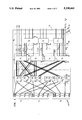
- FIG. 2 schematically illustrates an example of the operation of the merging network of FIG. 1.
- FIG. 3 schematically illustrates a further example of the operation of the merging network of FIG. 1.
- FIG. 1 illustrates a merging network 10 in accordance with an illustrative embodiment of the present invention.
- the network 10 has a plurality of inputs 20.
- the inputs 20 receive m ordered lists of numbers
- the first list A comprises
- the second list A 2 comprises
- the m th list A m comprises
- the total number of network inputs 20 may be expressed as
- the network 10 also comprises the outputs 32.
- a single ordered list of numbers d(1),d(2), . . . is formed by the network 10 at the outputs 32.
- the list of numbers d(1),d(2), . . . is formed from the numbers contained in the input lists A 1 , A 2 , . . . ,A m .
- the network 10 of FIG. 1 has r 1 +r 2 +. . . +r m outputs 32.
- the merging network 10 of FIG. 1 comprises three stages 12, 14, and 16. Each of these stages comprises one or more comparator modules.
- comparator module refers to a circuit or other data processing unit which receives a group of numbers at its inputs and sorts these numbers into an ordered list which appears at its outputs.
- the individual comparator modules 12, 14, and 16 may themselves be Batcher networks.
- the modules B j of the first stage 12 have the inputs 22.
- Each comparator module B j of the first stage 12 has a plurality of outputs 24.
- Each of the intervals is designated I j ,i, which indicates the i th output interval of the comparator module B j .
- the outputs 24 of comparator module B j are divided into the intervals I 2 ,1, I 2 ,2, . . . , I 2 ,k.
- each interval I j ,i includes a subset of the outputs of the corresponding comparator module B j . Some of the subsets may be empty.
- Each of the comparator modules C i in the stage 14 has a set of inputs 26 and a set of outputs 28.
- the output interval I j ,i associated with the comparator module B j of stage 12 is connected to a subset of the inputs 26 of the comparator module C i of stage 14.
- the outputs in the interval I 1 ,1 of the comparator module B 1 in the stage 12 are connected to the comparator module C 1 in the stage 14
- the outputs in the interval I 1 ,2 of the comparator module B 1 are connected to the comparator module C 2
- the outputs in the interval I 1 ,k are connected to the comparator module C k .
- the outputs in the interval I 2 ,1 of the comparator module B 2 of the stage 12 are connected to the comparator module C 1 of the stage 14, the outputs in the interval I 2 ,2 are connected to the comparator module C 2 and the outputs of the interval I 2 ,k are connected to the comparator module C k .
- the number which appears on an output 24 of comparator B j with index x j is b j (x j ).
- the interval I j ,i of the comparator module B j of the stage 12 may be expressed as
- x j ,i-1 is the last output in the interval I j ,i-1 so that x j ,i-1 +1 is the first output in the interval I j ,i and x j ,i is the last output in the interval I j ,i.
- the last output in the interval I 1 ,1 of the comparator module B 1 of stage 12 is x 1 ,1.
- the first output in the interval I 1 ,2 is x 1 ,1 +1.
- the last output in the interval I 1 ,2 is x 1 ,2.
- the interval I 1 ,2 may be (represented as
- the third stage 16 of the merging network 10 of FIG. 1 comprises a plurality of inputs 29 and a plurality of outputs 30.
- Each input 29 of the stage 16 is connected to a corresponding output 28 of the stage 14.
- Each output 30 of the stage 16 is connected to (or forms) a corresponding one of the network outputs 32.
- the connection pattern between the outputs 28 of the stage 14 and the inputs 29 of the stage 16 and between the outputs 30 of the stage 16 and network outputs 32 is known as a horizontal connection pattern (because the rows are horizontal).
- the last output of the comparator C 1 has the index y 1
- the last output of the comparator C k has the index y k .
- Each module D i has a set of inputs 34 and a set of outputs 36.
- Each input 34 is formed by one of the inputs 29 to the third stage 16.
- Each output 36 is formed by one of the outputs 30 of the third stage 16.
- the index values x j ,i (i.e. the last output of each interval I j ,i associated with the comparator module B j of stage 12), y i (i.e. the last output of each comparator module C i of the stage 14) and z i (i.e. the last output of each comparator module D i of stage 16) are determined.
- the index values provide the information that is necessary to construct a network of the type illustrated in FIG. 1.
- the index values may be used to determine the size and location of the various comparator modules B j , C i , D i in the network. These index values are determined such that the set of numbers d(1), d(2), . . . appearing at the network outputs 32 form a single sorted list.
- the index values x j ,i, y i and z i obey the equations
- Equations (1) and (2) imply that
- condition z i-1 ⁇ y i ⁇ z i implies that any input of the comparator D i in the stage 16 is connected to an output of the comparator C i or C i+1 in the stage 14.
- n j of a comparator module B j in the first stage 12 is given by
- the partition points x i ,j for stage 12, y i for stage 14, and z i for stage 16 are determined as follows.
- One way to minimize the complexity of the network 10 of FIG. 1 is to make the parameter k as large as possible, which means that the comparator modules C i and D i of the stages 14 and 16 are as small as possible. This is of course subject to the constraints of equations (4) and (6) above. The choice of parameters m,s, and k is flexible as long as the constraints of equations (4) and (6) are not violated. It is advantageous to make the comparator modules C i and D i as small as possible so that their internal complexity is minimized.
- the comparator modules C i and D i are themselves really sorting networks. If these comparator modules are too large, they themselves will have to be formed recursively from a plurality of merging networks.
- FIG. 2 illustrates an 18 ⁇ 18 merging network 100 constructed in accordance with Eq. (8).
- the network 100 has eighteen inputs 102.
- the list A 1 is formed by (a 1 (1), . . . ,a 1 (6)).
- the list A 2 is formed by (a 2 (1), . . . ,a 2 (6)).
- the list A 3 is formed by (a 3 (1), . . .
- the network 100 of FIG. 2 sorts the input lists A 1 , A 2 and A 3 into a single sorted output list which is formed from the numbers d(1),d(2), . . . ,d(18) appearing at the network outputs 103.
- the network 100 comprises three stages of comparator modules 112, 114, 116.
- the network inputs 102 are connected to the inputs 122 of the comparator modules B 1 , B 2 , B 3 of stage 12 using a mod(3) shuffle interconnection pattern.
- the outputs 124 of each of the comparator modules B 1 , B 2 and B 3 of stage 112 are partitioned into intervals I j ,i.
- the corresponding intervals I 1 ,1, I 1 ,2 and I 1 ,3 are illustrated in FIG. 2.
- each comparator module C i in the stage 114 has y i -y i-1 outputs and is therefore a 6 ⁇ 6 comparator module.
- the outputs in the intervals I 1 ,1, I 1 ,2 and I 1 ,3 are connected to a subset of the inputs 126 of C 1 , C 2 and C 3 , respectively.
- the stage 116 comprises the comparator modules D 1 and D 2 .
- the number of inputs z i -z i-1 of each comparator module D i is determined to be six.
- equation (8) is not the most optimal solution.
- a more optimal solution for determining the partition points x j ,i, y i , and z i for the modules B j , C i , and D i of stages 12, 14, and 16 of FIG. 1 may be obtained using the following iterative algorithm. ##STR1## Depending on the value of the initial condition z 0 there may be up to s different solutions which are obtained by this algorithm.
- FIG. 3 illustrates an 18 ⁇ 18 merging network 200 constructed in accordance with the iterative algorithm prescribed above.
- the 18 ⁇ 18 merging network 200 of FIG. 3 is more optimal than the 18 ⁇ 18 merging network 100 of FIG. 2.
- the merging network 200 of FIG. 3 receives three lists A 1 , A 2 and A 3 at its inputs 202 and outputs a single ordered list at the outputs 204.
- the network 200 comprises there stages 212, 214, 216.
- the stage 212 comprise the comparator modules B 1 , B 2 , and B 3 .
- Each of the comparator modules in the stage 212 has six inputs 218 and six outputs 220.
- the network inputs 202 are connected to the inputs 218 using a mod(3) shuffle interconnection pattern.
- the outputs 220 are divided into intervals I j ,i in the manner described above.
- the stage 214 comprises seven comparator modules C 1 , . . . ,C 7 .
- Each comparator module C 1 , . . . , C 7 has one or more inputs 222 and one or more outputs 224.
- the outputs in the interval I j ,i of the comparator module B j of stage 212 are connected to a subset of the inputs 222 of the comparator module C i of stage 214.
- the intermediate stage 114 comprises three 6 ⁇ 6 comparator modules.
- the intermediate stage 214 comprises seven comparator modules none of which is larger than 3 ⁇ 3. This is more optimal because the 3 ⁇ 3 comparator modules are of simpler internal construction.
- the comparator module C 7 is shown in phantom. The reason is that C 7 is a one-by-one comparator module which may be replaced by the wire 225.
- the stage 216 comprises six comparator modules D 1 , . . . , D 6 none of which is larger than three-by-three. There is more optimal than the 6 ⁇ 6 comparator modules utilized in the stage 116 of the network 100 of FIG. 2.
Abstract
Description
A.sub.1, A.sub.2, . . . , A.sub.m.
{a.sub.1 (1),a.sub.1 (2), . . . a.sub.1 (j), . . . ,a.sub.1 (s), . . . a.sub.1 (r.sub.1)}.
{a.sub.2 (1), a.sub.2 (2), . . . , a.sub.2 (j), . . . , a.sub.2 (s), . . . , a.sub.2 (r.sub.2)}.
{a.sub.m (1), a.sub.m (2), . . . , a.sub.m (j), . . . , a.sub.m (s), . . . , a.sub.m (r.sub.m)}.
r.sub.1 +r.sub.2 +. . . r.sub.m.
I.sub.j,i =(x.sub.j,i-1 +1, . . . , x.sub.j,i)
I.sub.1,2 ={x.sub.1,1 +1, . . . ,x.sub.1,2 }).
z.sub.i-1 -m(j-1)+(m-1)(s-1)≦sx.sub.j,i ≦z.sub.i -m(j-1)+(s-1) (1)
z.sub.i-1 ≦y.sub.i ≦z.sub.i, (2)
b.sub.j (x.sub.j,i)≦d(z.sub.i) and that b.sub.j (x.sub.i,j +1)≧d(z.sub.i-1 +1)
n.sub.j =p.sub.1 +. . . +p.sub.m +μ(q.sub.1 -j)+. . . +μ(q.sub.m -j), (3)
z.sub.i -z.sub.i-1 ≧(m-2)(s-2) (4)
x.sub.j,i -x.sub.j,i-1 ≧(m-2)(s-1)/s (5)
(m-2)(s-1)(k-l)<n (6)
y.sub.i -y.sub.i-1 ≧(m-2)(s-1) (7)
Claims (10)
Priority Applications (1)
| Application Number | Priority Date | Filing Date | Title |
|---|---|---|---|
| US07/736,469 US5220664A (en) | 1991-07-26 | 1991-07-26 | Merging network with three or more simultaneous inputs |
Applications Claiming Priority (1)
| Application Number | Priority Date | Filing Date | Title |
|---|---|---|---|
| US07/736,469 US5220664A (en) | 1991-07-26 | 1991-07-26 | Merging network with three or more simultaneous inputs |
Publications (1)
| Publication Number | Publication Date |
|---|---|
| US5220664A true US5220664A (en) | 1993-06-15 |
Family
ID=24959989
Family Applications (1)
| Application Number | Title | Priority Date | Filing Date |
|---|---|---|---|
| US07/736,469 Expired - Lifetime US5220664A (en) | 1991-07-26 | 1991-07-26 | Merging network with three or more simultaneous inputs |
Country Status (1)
| Country | Link |
|---|---|
| US (1) | US5220664A (en) |
Cited By (8)
| Publication number | Priority date | Publication date | Assignee | Title |
|---|---|---|---|---|
| US5440549A (en) * | 1993-04-22 | 1995-08-08 | Washington University | Broadband multi-channel switch with multicasting capability |
| US5532948A (en) * | 1993-01-13 | 1996-07-02 | Sumitomo Metal Industries, Ltd. | Rank order filter |
| US5621908A (en) * | 1992-10-21 | 1997-04-15 | Fujitsu Limited | Parallel sorting system to reduce the amount of communication between processing devices |
| US6418424B1 (en) | 1991-12-23 | 2002-07-09 | Steven M. Hoffberg | Ergonomic man-machine interface incorporating adaptive pattern recognition based control system |
| US6757284B1 (en) * | 2000-03-07 | 2004-06-29 | Cisco Technology, Inc. | Method and apparatus for pipeline sorting of ordered streams of data items |
| US8892495B2 (en) | 1991-12-23 | 2014-11-18 | Blanding Hovenweep, Llc | Adaptive pattern recognition based controller apparatus and method and human-interface therefore |
| US9535563B2 (en) | 1999-02-01 | 2017-01-03 | Blanding Hovenweep, Llc | Internet appliance system and method |
| US11249720B2 (en) * | 2018-11-19 | 2022-02-15 | Carnegie Mellon University | High performance merge sort with scalable parallelization and full-throughput reduction |
Citations (5)
| Publication number | Priority date | Publication date | Assignee | Title |
|---|---|---|---|---|
| US4410960A (en) * | 1980-02-05 | 1983-10-18 | Nippon Electric Co., Ltd. | Sorting circuit for three or more inputs |
| US4567572A (en) * | 1983-02-22 | 1986-01-28 | The United States Of America As Represented By The Director Of The National Security Agency | Fast parallel sorting processor |
| US4628483A (en) * | 1982-06-03 | 1986-12-09 | Nelson Raymond J | One level sorting network |
| US4651301A (en) * | 1983-06-24 | 1987-03-17 | Carl-Zeiss-Stiftung | Circuit arrangement for performing rapid sortation or selection according to rank |
| US4799152A (en) * | 1984-10-12 | 1989-01-17 | University Of Pittsburgh | Pipeline feedback array sorter with multi-string sort array and merge tree array |
-
1991
- 1991-07-26 US US07/736,469 patent/US5220664A/en not_active Expired - Lifetime
Patent Citations (5)
| Publication number | Priority date | Publication date | Assignee | Title |
|---|---|---|---|---|
| US4410960A (en) * | 1980-02-05 | 1983-10-18 | Nippon Electric Co., Ltd. | Sorting circuit for three or more inputs |
| US4628483A (en) * | 1982-06-03 | 1986-12-09 | Nelson Raymond J | One level sorting network |
| US4567572A (en) * | 1983-02-22 | 1986-01-28 | The United States Of America As Represented By The Director Of The National Security Agency | Fast parallel sorting processor |
| US4651301A (en) * | 1983-06-24 | 1987-03-17 | Carl-Zeiss-Stiftung | Circuit arrangement for performing rapid sortation or selection according to rank |
| US4799152A (en) * | 1984-10-12 | 1989-01-17 | University Of Pittsburgh | Pipeline feedback array sorter with multi-string sort array and merge tree array |
Non-Patent Citations (10)
| Title |
|---|
| "An O (nlogn) Sorting Network", M. Ajtai et al., Proc. 15th Annual ACM Symposium on Theory of Computing, 1983, pp. 1-9. |
| "Sorting Networks and Their Applications", K. E. Batcher, AFIPS Proceeding of the Spring Joint Computer Conference, 1960, pp. 307-318. |
| "The Art of Computer Programming", D. E. Knuth, vol. 3, Addison Wesley, Reading, Mass. 1973. |
| "Tight Bounds on the Complexity of Parallel Sorting", F. T. Leighton, IEEE Trans. on Computer, vol. 34, No. 4, 1985, pp. 344-354. |
| An O (nlogn) Sorting Network , M. Ajtai et al., Proc. 15th Annual ACM Symposium on Theory of Computing, 1983, pp. 1 9. * |
| Bather K. E. "Sorting Networks and their Applications" AFIPS Spring Joint Computer Conference Proceedings, 1968, pp. 307-314. |
| Bather K. E. Sorting Networks and their Applications AFIPS Spring Joint Computer Conference Proceedings, 1968, pp. 307 314. * |
| Sorting Networks and Their Applications , K. E. Batcher, AFIPS Proceeding of the Spring Joint Computer Conference, 1960, pp. 307 318. * |
| The Art of Computer Programming , D. E. Knuth, vol. 3, Addison Wesley, Reading, Mass. 1973. * |
| Tight Bounds on the Complexity of Parallel Sorting , F. T. Leighton, IEEE Trans. on Computer, vol. 34, No. 4, 1985, pp. 344 354. * |
Cited By (9)
| Publication number | Priority date | Publication date | Assignee | Title |
|---|---|---|---|---|
| US6418424B1 (en) | 1991-12-23 | 2002-07-09 | Steven M. Hoffberg | Ergonomic man-machine interface incorporating adaptive pattern recognition based control system |
| US8892495B2 (en) | 1991-12-23 | 2014-11-18 | Blanding Hovenweep, Llc | Adaptive pattern recognition based controller apparatus and method and human-interface therefore |
| US5621908A (en) * | 1992-10-21 | 1997-04-15 | Fujitsu Limited | Parallel sorting system to reduce the amount of communication between processing devices |
| US5532948A (en) * | 1993-01-13 | 1996-07-02 | Sumitomo Metal Industries, Ltd. | Rank order filter |
| US5737251A (en) * | 1993-01-13 | 1998-04-07 | Sumitomo Metal Industries, Ltd. | Rank order filter |
| US5440549A (en) * | 1993-04-22 | 1995-08-08 | Washington University | Broadband multi-channel switch with multicasting capability |
| US9535563B2 (en) | 1999-02-01 | 2017-01-03 | Blanding Hovenweep, Llc | Internet appliance system and method |
| US6757284B1 (en) * | 2000-03-07 | 2004-06-29 | Cisco Technology, Inc. | Method and apparatus for pipeline sorting of ordered streams of data items |
| US11249720B2 (en) * | 2018-11-19 | 2022-02-15 | Carnegie Mellon University | High performance merge sort with scalable parallelization and full-throughput reduction |
Similar Documents
| Publication | Publication Date | Title |
|---|---|---|
| US4516238A (en) | Self-routing switching network | |
| US4799152A (en) | Pipeline feedback array sorter with multi-string sort array and merge tree array | |
| US5126999A (en) | Method and apparatus for input-buffered asynchronous transfer mode switching | |
| US5123011A (en) | Modular multistage switch for a parallel computing system | |
| JP2659421B2 (en) | Self-routing channel | |
| JPS62155648A (en) | Packet switch device and method for distributing copies of data packet to a plurality of addresses | |
| US5469154A (en) | Multiconnection switching networks | |
| US5299317A (en) | Method and apparatus for simulating an interconnection network | |
| CA2006393C (en) | Modular expandable digital single-stage switching network in atm (asynchronous transfer mode) technology for a fast packet-switched transmission of information | |
| US5220664A (en) | Merging network with three or more simultaneous inputs | |
| Koppelman et al. | A self-routing permutation network | |
| JP2834571B2 (en) | Optical connection network | |
| US5319639A (en) | Crossbar with return net for scalable self-routing non-blocking message switching and routing system | |
| US5216420A (en) | Matrix sorting network for sorting N inputs onto N outputs | |
| US7065076B1 (en) | Modular scalable switching networks | |
| US6021131A (en) | Sorting networks having enhanced layout | |
| US4685128A (en) | Method and network for transmitting addressed signal samples from any network input to an addressed network output | |
| Chen | A survey of multistage interconnection networks in fast packet switches | |
| Aghakhani et al. | A novel routing algorithm in benes networks | |
| US6088353A (en) | Sorting networks having reduced-area layouts | |
| Rana | A control algorithm for 3-stage non-blocking networks | |
| Douglass | Rearrangeable three-stage interconnection networks and their routing properties | |
| Lee et al. | New self-routing permutation networks | |
| Rajasekaran | Basic algorithms on parallel optical models of computing | |
| Rajasekaran | Basic Algorithms on Optical Models of Computing1 |
Legal Events
| Date | Code | Title | Description |
|---|---|---|---|
| AS | Assignment |
Owner name: BELL COMMUNICATIONS RESEARCH, INC. A CORP. OF DE, Free format text: ASSIGNMENT OF ASSIGNORS INTEREST.;ASSIGNOR:LEE, TONY T.;REEL/FRAME:005793/0629 Effective date: 19910725 |
|
| STCF | Information on status: patent grant |
Free format text: PATENTED CASE |
|
| FEPP | Fee payment procedure |
Free format text: PAYOR NUMBER ASSIGNED (ORIGINAL EVENT CODE: ASPN); ENTITY STATUS OF PATENT OWNER: LARGE ENTITY |
|
| FPAY | Fee payment |
Year of fee payment: 4 |
|
| AS | Assignment |
Owner name: TELCORDIA TECHNOLOGIES, INC., NEW JERSEY Free format text: CHANGE OF NAME;ASSIGNOR:BELL COMMUNICATIONS RESEARCH, INC.;REEL/FRAME:010263/0311 Effective date: 19990316 |
|
| FPAY | Fee payment |
Year of fee payment: 8 |
|
| FPAY | Fee payment |
Year of fee payment: 12 |
|
| AS | Assignment |
Owner name: JPMORGAN CHASE BANK, N.A., AS ADMINISTRATIVE AGENT Free format text: SECURITY AGREEMENT;ASSIGNOR:TELCORDIA TECHNOLOGIES, INC.;REEL/FRAME:015886/0001 Effective date: 20050315 |
|
| AS | Assignment |
Owner name: TELCORDIA TECHNOLOGIES, INC., NEW JERSEY Free format text: TERMINATION AND RELEASE OF SECURITY INTEREST IN PATENT RIGHTS;ASSIGNOR:JPMORGAN CHASE BANK, N.A., AS ADMINISTRATIVE AGENT;REEL/FRAME:019520/0174 Effective date: 20070629 Owner name: TELCORDIA TECHNOLOGIES, INC.,NEW JERSEY Free format text: TERMINATION AND RELEASE OF SECURITY INTEREST IN PATENT RIGHTS;ASSIGNOR:JPMORGAN CHASE BANK, N.A., AS ADMINISTRATIVE AGENT;REEL/FRAME:019520/0174 Effective date: 20070629 |
|
| AS | Assignment |
Owner name: WILMINGTON TRUST COMPANY, AS COLLATERAL AGENT, DEL Free format text: SECURITY AGREEMENT;ASSIGNOR:TELCORDIA TECHNOLOGIES, INC.;REEL/FRAME:019562/0309 Effective date: 20070629 Owner name: WILMINGTON TRUST COMPANY, AS COLLATERAL AGENT,DELA Free format text: SECURITY AGREEMENT;ASSIGNOR:TELCORDIA TECHNOLOGIES, INC.;REEL/FRAME:019562/0309 Effective date: 20070629 |
|
| FEPP | Fee payment procedure |
Free format text: PAYER NUMBER DE-ASSIGNED (ORIGINAL EVENT CODE: RMPN); ENTITY STATUS OF PATENT OWNER: LARGE ENTITY Free format text: PAYOR NUMBER ASSIGNED (ORIGINAL EVENT CODE: ASPN); ENTITY STATUS OF PATENT OWNER: LARGE ENTITY |
|
| AS | Assignment |
Owner name: TELCORDIA TECHNOLOGIES, INC., NEW JERSEY Free format text: RELEASE OF SECURITY INTEREST;ASSIGNOR:WILMINGTON TRUST COMPANY;REEL/FRAME:022408/0410 Effective date: 20090220 Owner name: TELCORDIA TECHNOLOGIES, INC.,NEW JERSEY Free format text: RELEASE OF SECURITY INTEREST;ASSIGNOR:WILMINGTON TRUST COMPANY;REEL/FRAME:022408/0410 Effective date: 20090220 |
|
| AS | Assignment |
Owner name: TELCORDIA LICENSING COMPANY LLC, NEW JERSEY Free format text: ASSIGNMENT OF ASSIGNORS INTEREST;ASSIGNOR:TELCORDIA TECHNOLOGIES, INC.;REEL/FRAME:022878/0821 Effective date: 20090616 |
|
| AS | Assignment |
Owner name: TELCORDIA TECHNOLOGIES, INC.,NEW JERSEY Free format text: RELEASE;ASSIGNOR:WILMINGTON TRUST COMPANY, AS COLLATERAL AGENT;REEL/FRAME:024515/0622 Effective date: 20100430 Owner name: TELCORDIA TECHNOLOGIES, INC., NEW JERSEY Free format text: RELEASE;ASSIGNOR:WILMINGTON TRUST COMPANY, AS COLLATERAL AGENT;REEL/FRAME:024515/0622 Effective date: 20100430 |
|
| AS | Assignment |
Owner name: TTI INVENTIONS A LLC, DELAWARE Free format text: ASSIGNMENT OF ASSIGNORS INTEREST;ASSIGNOR:TELCORDIA LICENSING COMPANY, LLC;REEL/FRAME:027843/0205 Effective date: 20111102 |