US5241159A - Multi-zone heating for a fuser roller - Google Patents
Multi-zone heating for a fuser roller Download PDFInfo
- Publication number
- US5241159A US5241159A US07/849,543 US84954392A US5241159A US 5241159 A US5241159 A US 5241159A US 84954392 A US84954392 A US 84954392A US 5241159 A US5241159 A US 5241159A
- Authority
- US
- United States
- Prior art keywords
- heat
- fusing
- cylindrical member
- heat elements
- elements
- Prior art date
- Legal status (The legal status is an assumption and is not a legal conclusion. Google has not performed a legal analysis and makes no representation as to the accuracy of the status listed.)
- Expired - Lifetime
Links
Images


Classifications
-
- H—ELECTRICITY
- H05—ELECTRIC TECHNIQUES NOT OTHERWISE PROVIDED FOR
- H05B—ELECTRIC HEATING; ELECTRIC LIGHT SOURCES NOT OTHERWISE PROVIDED FOR; CIRCUIT ARRANGEMENTS FOR ELECTRIC LIGHT SOURCES, IN GENERAL
- H05B3/00—Ohmic-resistance heating
- H05B3/0095—Heating devices in the form of rollers
-
- G—PHYSICS
- G03—PHOTOGRAPHY; CINEMATOGRAPHY; ANALOGOUS TECHNIQUES USING WAVES OTHER THAN OPTICAL WAVES; ELECTROGRAPHY; HOLOGRAPHY
- G03G—ELECTROGRAPHY; ELECTROPHOTOGRAPHY; MAGNETOGRAPHY
- G03G15/00—Apparatus for electrographic processes using a charge pattern
- G03G15/20—Apparatus for electrographic processes using a charge pattern for fixing, e.g. by using heat
- G03G15/2003—Apparatus for electrographic processes using a charge pattern for fixing, e.g. by using heat using heat
- G03G15/2014—Apparatus for electrographic processes using a charge pattern for fixing, e.g. by using heat using heat using contact heat
- G03G15/2039—Apparatus for electrographic processes using a charge pattern for fixing, e.g. by using heat using heat using contact heat with means for controlling the fixing temperature
- G03G15/2042—Apparatus for electrographic processes using a charge pattern for fixing, e.g. by using heat using heat using contact heat with means for controlling the fixing temperature specially for the axial heat partition
-
- G—PHYSICS
- G03—PHOTOGRAPHY; CINEMATOGRAPHY; ANALOGOUS TECHNIQUES USING WAVES OTHER THAN OPTICAL WAVES; ELECTROGRAPHY; HOLOGRAPHY
- G03G—ELECTROGRAPHY; ELECTROPHOTOGRAPHY; MAGNETOGRAPHY
- G03G15/00—Apparatus for electrographic processes using a charge pattern
- G03G15/20—Apparatus for electrographic processes using a charge pattern for fixing, e.g. by using heat
- G03G15/2003—Apparatus for electrographic processes using a charge pattern for fixing, e.g. by using heat using heat
- G03G15/2014—Apparatus for electrographic processes using a charge pattern for fixing, e.g. by using heat using heat using contact heat
- G03G15/2053—Structural details of heat elements, e.g. structure of roller or belt, eddy current, induction heating
Definitions
- This invention relates to a heated fuser roller as is commonly used in copying machines, and more particularly to a heated fuser roller having multiple groupings of internal heat elements.
- a typical approach to fusing a toner image is by a hot roller-pressure fuser apparatus.
- the paper, with the toner image thereon is passed between a pair of rollers, at least one of which is heated.
- the heated roller formed of a hollow cylinder having a radiant heater, such as an infrared lamp, centrally located within the cylinder, to heat the roller.
- the paper to which the toner image is electrostatically adhered is passed through a nip, formed between the rollers, with the toner image contacting the fuser roller to effect heating of the toner image within the nip.
- a thermostat monitoring the process, intermittently interrupts or restores the current flow, to the infrared lamp, in an attempt to maintain the surface roller temperature at a predetermined optimum value.
- 4,266,115, 4,377,366 and 4,585,325, is able to adjust to all the varying demands of non-uniform thermal output during the fusing process; and (3) adjustments must be made for different machine modes, i.e., standby, off, continuous operation.
- a fusing roller having a cylindrical member of thermally conducting material with a peripheral surface at which a receiver is fused.
- a cylindrical member Positioned within the cylindrical member are at least three groupings of heat elements, such that individual heat elements of the same group are of the same heating capacity and individual heat elements not of the same group are of different heating capacity and with each group having a different heating capacity for providing an even heat flow distribution to specific areas about the peripheral surface of the cylindrical member.
- heat sensing means positioned within the cylindrical member are heat sensing means adjacent to the heat elements for sensing the heat generated by the heating elements.
- FIG. 1 is a schematic sectional view of a prior art copier.
- FIG. 2 is a perspective view of the fuser roller in accordance with the present invention.
- FIG. 3 is a schematic view of the various heating elements in accordance with the present invention.
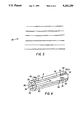
- FIG. 4 is a perspective view of the fusing roller of the present invention, showing heat elements of varying capacity within the fuser roller.
- FIG. 5 is a perspective view of the fuser roller and logic circuit in accordance with the present invention.
- FIG. 6 is a schematic side view of a prior art multi-ring slip ring.
- FIG. 7 is a schematic top view of a prior art paper or envelope tray with limit switches.
- FIG. 8 is a perspective view of an example of one grouping pattern for the heat elements of the fusing roller.
- FIG. 9 is a perspective view of another example of a grouping pattern for the heat elements of the fusing roller.
- FIG. 10 is a perspective view of yet another example of a grouping pattern for the heat elements of the fusing roller.
- FIG. 11 is a perspective view of still another example of a grouping pattern for the heat elements of the fusing roller.
- FIG. 1 The environment of a multi-zoned heat fusing roller 4, see FIG. 2, which is the subject matter of the present invention, is a reproduction apparatus 1, see FIG. 1, such as an electrophotographic copying machine.
- an electrophotographic copying machine 1 has various stations which include a rotating drum 5 or a belt, said belt not being shown, but known in the art.
- a photoconductive surface 6, such as a selenium alloy, is secured around the outer surface of drum 5.
- drum 5 rotates, in the direction of arrow 7, photoconductive surface 6, of drum 5, moves adjacent to the various processing stations disposed around the periphery of drum 5.
- a portion of photoconductive surface 6 moves adjacent to a charging apparatus 8 which includes a corona generating device 9 that imparts a uniform electrostatic charge to photoconductor surface 6.
- a charging apparatus 8 which includes a corona generating device 9 that imparts a uniform electrostatic charge to photoconductor surface 6.
- drum 5 As drum 5 continues to rotate, the image on photoconductive surface 6 is carried past a developer station 11, where toner particles 12 are applied to the image. This is typically accomplished by a rotating magnetic roller 13 that picks up toner particles 12, from a hopper 14, and brings them into contact with the image on photoconductive surface 6 to electrostatically develop the image.
- a transfer station 20 which includes a corona transfer charging apparatus 21.
- a receiver 22 such as a paper sheet of varying size or an envelope, from a supply of sheets or envelopes 23, stored in removable universal tray 24, also arrives at transfer station 20.
- copier 1 may have multiple trays with each tray containing a different size of image receiver.
- Receiver 22 is fed to transfer station 20 by a feed roller 25 which urges receiver 22 through a guide 26 and into the nip of queuing rollers 27.
- the queuing rollers 27 are actuated to feed receiver 22 along guide 26 and into contact with the developed image carried on photoconductive surface 6.
- toner particles 12 are attracted from photoconductive surface 6, toward receiver 22, to which they loosely adhere.
- receiver 22 is stripped away from drum 5, by a suitable apparatus, and advanced, by belt conveyor 28, to a fusing station 2.
- receiver 22 passes through fusing station 2, which includes a fusing roller 3, toner particles 12, now residing on copy paper 22, are heated and fused to copy paper 22, by the interaction of fuser roller 3 and back up roller 29, thereby forming a permanent copy of the original document on receiver 22.
- receiver 22 is separated from fuser station 2 and advanced to a catch tray 30 for subsequent removal, from the copier, by an operator.
- Fusing roller 4 is manufactured with a core 4(a) of a ceramic material, such as refractory oxides, like Al 2 O 3 , Mulite, M g O or their mixes and nitrides.
- a thermally conductive cylindrical member 4(b) Surrounding core 4(a) is a thermally conductive cylindrical member 4(b), constructed of a material such as graphite, silicon carbide, aluminum, copper, silver, platinum or an equivalent thermally conductive material.
- this thermally conductive member 4(b), surrounding core 4(a) are multiple bores 39, to accommodate any one of a number of heat elements 36; see FIG. 3.
- heat elements 36 When heat elements 36 are inserted into bores 39, they are inserted in pattern groupings such as shown in FIGS. 8, 9, 10 and 11. While FIGS. 8, 9, 10 and 11 show each pattern grouping in individual rollers, this is only for clarity of discussion, it being understood that all pattern grouping, such as shown in FIGS. 8, 9, 10 and 11, as well as others that may be used, but not shown, are located in a single fusing roller 4.
- each individual pattern grouping is comprised of heat elements 36 of the same heating capacity.
- all heat elements 36a have the same heat capacity; all heat elements 36b have the same heat capacity; all heat elements 36c have the same heat capacity and all heat elements 36d have the same heat capacity, but in relation to each other the individual heating capacities of heat elements 36a, 36b, 36c and 36d, as shown in FIGS. 8, 9, 10 and 11, are different.
- the group insertion pattern of heat elements 36 is such that the concentrated heat flow from each individual grouping pattern, which consist of at least two heat elements 36 evenly spaced about the axis of fusing roller 4, is able to quickly produce and maintain a specified fusing temperature range at a designated area or areas about the periphery of the surface of fusing roller 4.
- fusing roller 4 contains a multitude of grouping patterns, such as those shown in FIGS. 8, 9, 10, and 11, as well as grouping patterns not shown, by using the concentrated heat flow of an individual grouping pattern or combination of grouping patterns, a multitude of different temperatures may be created and maintained, at designated areas about the peripheral surface of fusing roller 4 to optimize the fusing process. It is therefore just a matter of determining what individual grouping pattern or combination of grouping patterns are required to provide and maintain the predetermined optimum fusing temperature or temperature range, at the surface of fusing roller 4, for receiver 22 being fused.
- the surface fusing temperature may be adjusted by varying the electrical current supplied to the individual pattern groupings as later discussed.
- This ability to control the temperature, at the surface of fusing roller 4, by pattern grouping and adjustment of electrical current to the individual pattern groupings is a significant step in surface temperature fusing control over the prior art.
- the prior art at most, used only two different heat elements to control fusing temperature, thereby limiting the number of areas along the periphery of the fusing roller that could be controlled, the amount of control that could be applied to those areas and the response time for varying the fusing temperature.
- the preferred materials for heat elements 36 are materials such as nichrome, kanthal, super kanthal, inconel (Ni-based), ruthenium oxide and nickel oxide.
- the difference in heating capacity of heat elements 36 is obtained by varying the coil lengths or coil positions of heat elements 36; see FIG. 3.
- the heat output, as previously stated, of each individual pattern grouping of heat elements 36 may be changed by varying the amount of current supplied to that particular pattern grouping of heat elements 36.
- all heat elements 36, within a particular pattern grouping have their leads 40, see FIG. 6, connected to a current source 50, through a common electrical connecting means 41, such as a ring of a multi-ring slip ring or its equivalent located at both outer end portions 42, see FIG. 5, of fusing roller 4.
- a common electrical connecting means 41 such as a ring of a multi-ring slip ring or its equivalent located at both outer end portions 42, see FIG. 5, of fusing roller 4.
- sensing means 51 such as limit switches, which are known in the art, see FIG. 7, are positioned in tray 24.
- Limit switches 51 sense the size of receiver 22, in tray 24, and convey that size information to a logic and control unit 31, of a type that is well known in the art; see FIG. 5.
- logic and control unit 31 Upon logic and control unit 31 receiving an input from limit switches 51, identifying receiver 22 contained in tray 24, logic and control unit 31 outputs a signal to current source 50, indicating what pattern grouping or combination of pattern groupings, of heat elements 36, are to be supplied with electrical current and the amount of electrical current to be supplied to each individual pattern grouping, so as to produce a heat flow, to the surface of fusing roller 4, that will provide the predetermined optimum surface fusing temperature to a designated area or areas of fusing roller 4 to fuse receiver 22.
- heat sensors 34 such as thermistors, having a plus or minus 1% deviation, are positioned within fusing roller 4 adjacent heat elements 36; see FIG. 4.
- the output of each heat sensor 34 produces a signal, corresponding to the heat sensor, which signal is then transmitted, to logic and control unit 31, through leads 34(a) and a ring or rings of multi-ring slip ring 34(c), see FIG. 5, located at opposite ends of fusing roller 4.
- Logic and control unit 31 then compares the signal of each interior heat sensor 34 to a known signal range that represents the predetermined optimum surface temperature of fusing roller 4 to fuse receiver 22 that had been sensed in tray 24. If said comparison results in a value that is more or less than the known signal range, logic and control unit 31 signals current source 50 to adjust the flow of electrical current to one or more groupings of heat elements 36 until the signal from heat sensors 34 is within the known signal range, signifying that the predetermined optimum fusing temperature has been reached. When the signal from heat sensors 34 is within the known signal range, logic and control unit 31 again adjusts the current flow, from current source 50, to the pattern grouping or groupings, of heat elements 36, to maintain the proper fusing temperature at the surface of fusing roller 4.
- the first to use the output of surface heat sensors 34x, as opposed to the output from interior heat sensors 34, as the signal that logic and control unit 31 uses to make the comparisons with the known signal range and adjust the current flow based upon that comparison.
- the second as a checking means, whereby if the signal from sensors 34x, transmit a signal that deviates by more than a certain percent from the known signal range, logic and control unit 31 will alert the operator of copier 1 that a fusing problem may exist.
- each individual pattern grouping, of heat elements 36 must be able to produce a specified fusing temperature range, in specified areas, about the periphery of the surface of fusing roller 4, the location of each pattern grouping, of heat elements 36, while being restricted as to its location between the ends of fusing roller 4, said pattern groupings are not restricted to a particular location between the axis of fusing roller 4 and the peripheral surface of fusing roller 4, since adjustments in the amount of electrical current supplied to any pattern grouping, of heat elements 36, will compensate for the distance between that pattern grouping, of heat element 36, and the surface of fusing roller 4.
- the pattern grouping or pattern groupings, of heat elements 36, used to supply heat for fusing normal 81/2 by 11 inch paper are located closest to the surface of fusing roller 4. This limits heat loss caused by heat travel through the interior of fusing roller 4 when 81/2 by 11 paper, the most used receiver, is being used and thereby conserves the most energy.
- a predetermined optimum surface fusing temperature for any receiver 22, sensed in tray 24, may be quickly produced and maintained at the surface of fusing roller 4.
- This monitoring and control of heat flow also conserves electrical energy and extends the life of fusing roller 4, since only electrical energy needed for proper fusing is generated and only the area of fusing roller 4, required to be heated, is heated thereby limiting the effects of fatiguing to fusing roller 4.
Abstract
Description
Claims (5)
Priority Applications (1)
| Application Number | Priority Date | Filing Date | Title |
|---|---|---|---|
| US07/849,543 US5241159A (en) | 1992-03-11 | 1992-03-11 | Multi-zone heating for a fuser roller |
Applications Claiming Priority (1)
| Application Number | Priority Date | Filing Date | Title |
|---|---|---|---|
| US07/849,543 US5241159A (en) | 1992-03-11 | 1992-03-11 | Multi-zone heating for a fuser roller |
Publications (1)
| Publication Number | Publication Date |
|---|---|
| US5241159A true US5241159A (en) | 1993-08-31 |
Family
ID=25305963
Family Applications (1)
| Application Number | Title | Priority Date | Filing Date |
|---|---|---|---|
| US07/849,543 Expired - Lifetime US5241159A (en) | 1992-03-11 | 1992-03-11 | Multi-zone heating for a fuser roller |
Country Status (1)
| Country | Link |
|---|---|
| US (1) | US5241159A (en) |
Cited By (62)
| Publication number | Priority date | Publication date | Assignee | Title |
|---|---|---|---|---|
| US5325166A (en) * | 1993-06-18 | 1994-06-28 | Lexmark International, Inc. | Fuser overheat control |
| US5350896A (en) * | 1993-11-22 | 1994-09-27 | Xerox Corporation | Dual lamp fuser |
| US5402220A (en) * | 1992-08-25 | 1995-03-28 | Ricoh Company, Ltd. | Fixing device for an image forming apparatus featuring a fixing belt and heating control |
| US5436431A (en) * | 1993-02-19 | 1995-07-25 | Sharp Kabushiki Kaisha | Toner image fixing device having improved lamp heater |
| US5450793A (en) * | 1993-05-04 | 1995-09-19 | Markem Corporation | Printing or marking apparatus with exchangeable heating structure |
| WO1995030941A1 (en) * | 1994-05-09 | 1995-11-16 | Minnesota Mining And Manufacturing Company | Apparatus for controlling the temperature of and a moveable, electrically heated object |
| US5485260A (en) * | 1993-12-01 | 1996-01-16 | Hitachi, Ltd. | Fixing device, fixing method, and recording apparatus |
| US5640231A (en) * | 1993-06-10 | 1997-06-17 | Canon Kabushiki Kaisha | Image forming apparatus and temperature control device for fixing unit for use therewith |
| US5666627A (en) * | 1994-04-25 | 1997-09-09 | Nec Corporation | Fixing device which utilizes heat generated by electromagnetic induction |
| US5671462A (en) * | 1994-07-22 | 1997-09-23 | Canon Kabushiki Kaisha | Fixing device having a power supply control element for controlling a temperature of a heat member |
| US5760375A (en) * | 1996-10-08 | 1998-06-02 | Hall; Timothy G. | Heated rollers |
| US5862436A (en) * | 1996-10-25 | 1999-01-19 | Hitachi Koki Co., Ltd. | Fixing apparatus and method for electrophotographic apparatus including temperature detecting mechanism for heat roller |
| US5946025A (en) * | 1997-09-29 | 1999-08-31 | Imation Corp. | Thermal drum processor assembly with roller mounting assembly for a laser imaging device |
| US6007971A (en) * | 1992-09-09 | 1999-12-28 | Minnesota Mining And Manufacturing | Apparatus, system, and method for processing photothermographic elements |
| DE19820672C2 (en) * | 1997-05-09 | 2000-07-13 | Hitachi Koki Kk | Heating roller fixing device |
| US6091059A (en) * | 1995-09-11 | 2000-07-18 | Ushiodenki Kabushiki Kaisha | Heat roller device |
| US6091480A (en) * | 1997-07-17 | 2000-07-18 | 3M Innovative Properties Company | Film removal mechanism for use with a thermal drum processor system |
| US6133553A (en) * | 1997-01-20 | 2000-10-17 | Barmag Ag | Godet for advancing, guiding, and heating an advancing synthetic filament yarn |
| US6160983A (en) * | 1998-05-20 | 2000-12-12 | Hewlett-Packard Company | Heated fuser roller |
| US6168269B1 (en) * | 1997-01-30 | 2001-01-02 | Hewlett-Packard Co. | Heated inkjet print media support system |
| US6297476B1 (en) * | 1999-03-11 | 2001-10-02 | Konica Corporation | Thermally developing apparatus |
| US6389241B1 (en) * | 2001-01-16 | 2002-05-14 | Hewlett-Packard Company | Method and apparatus for hard copy control using automatic sensing devices |
| US20030235421A1 (en) * | 2002-06-19 | 2003-12-25 | Hooper Howard G. | Optimized toner fusing in a printing device |
| US20040149709A1 (en) * | 2002-06-03 | 2004-08-05 | Fuji Xerox Co., Ltd. | Heat roller |
| US20040233264A1 (en) * | 2003-05-24 | 2004-11-25 | Smith David E. | Media electrostatic hold down and conductive heating assembly |
| US20050190250A1 (en) * | 2004-02-26 | 2005-09-01 | Hewlett-Packard Development Company, L.P. | Media hold down system |
| US20070060457A1 (en) * | 2005-09-15 | 2007-03-15 | Eastman Kodak Company | Circumferentially variable surface temperature roller |
| EP2138906A2 (en) | 2008-06-25 | 2009-12-30 | Xerox Corporation | Fuser assemblies, xerographic apparatuses and methods of fusing toner on media |
| US20100209133A1 (en) * | 2009-02-17 | 2010-08-19 | Juergen Stresau | Roller to affect the temperature of a print substrate in a digital printer |
| US8528589B2 (en) | 2009-03-23 | 2013-09-10 | Raindance Technologies, Inc. | Manipulation of microfluidic droplets |
| US8535889B2 (en) | 2010-02-12 | 2013-09-17 | Raindance Technologies, Inc. | Digital analyte analysis |
| US20130240149A1 (en) * | 2012-03-15 | 2013-09-19 | Hung-Wei HUNG | Heating device for corrugated paper |
| US8592221B2 (en) | 2007-04-19 | 2013-11-26 | Brandeis University | Manipulation of fluids, fluid components and reactions in microfluidic systems |
| US8658430B2 (en) | 2011-07-20 | 2014-02-25 | Raindance Technologies, Inc. | Manipulating droplet size |
| US8772046B2 (en) | 2007-02-06 | 2014-07-08 | Brandeis University | Manipulation of fluids and reactions in microfluidic systems |
| US8841071B2 (en) | 2011-06-02 | 2014-09-23 | Raindance Technologies, Inc. | Sample multiplexing |
| US8871444B2 (en) | 2004-10-08 | 2014-10-28 | Medical Research Council | In vitro evolution in microfluidic systems |
| US20140376938A1 (en) * | 2013-06-25 | 2014-12-25 | Ricoh Company, Ltd. | Fixing device for fixing a toner image on a sheet-shaped recording medium and image formation apparatus |
| US9012390B2 (en) | 2006-08-07 | 2015-04-21 | Raindance Technologies, Inc. | Fluorocarbon emulsion stabilizing surfactants |
| US9150852B2 (en) | 2011-02-18 | 2015-10-06 | Raindance Technologies, Inc. | Compositions and methods for molecular labeling |
| US9273308B2 (en) | 2006-05-11 | 2016-03-01 | Raindance Technologies, Inc. | Selection of compartmentalized screening method |
| US9328344B2 (en) | 2006-01-11 | 2016-05-03 | Raindance Technologies, Inc. | Microfluidic devices and methods of use in the formation and control of nanoreactors |
| US9364803B2 (en) | 2011-02-11 | 2016-06-14 | Raindance Technologies, Inc. | Methods for forming mixed droplets |
| US9366632B2 (en) | 2010-02-12 | 2016-06-14 | Raindance Technologies, Inc. | Digital analyte analysis |
| US9399797B2 (en) | 2010-02-12 | 2016-07-26 | Raindance Technologies, Inc. | Digital analyte analysis |
| US9448172B2 (en) | 2003-03-31 | 2016-09-20 | Medical Research Council | Selection by compartmentalised screening |
| US9498759B2 (en) | 2004-10-12 | 2016-11-22 | President And Fellows Of Harvard College | Compartmentalized screening by microfluidic control |
| US9562837B2 (en) | 2006-05-11 | 2017-02-07 | Raindance Technologies, Inc. | Systems for handling microfludic droplets |
| US9562897B2 (en) | 2010-09-30 | 2017-02-07 | Raindance Technologies, Inc. | Sandwich assays in droplets |
| US9839890B2 (en) | 2004-03-31 | 2017-12-12 | National Science Foundation | Compartmentalised combinatorial chemistry by microfluidic control |
| US10052605B2 (en) | 2003-03-31 | 2018-08-21 | Medical Research Council | Method of synthesis and testing of combinatorial libraries using microcapsules |
| US10351905B2 (en) | 2010-02-12 | 2019-07-16 | Bio-Rad Laboratories, Inc. | Digital analyte analysis |
| US10457512B2 (en) | 2016-09-19 | 2019-10-29 | New Era Converting Machinery, Inc. | Automatic lapless butt material splice |
| US10520500B2 (en) | 2009-10-09 | 2019-12-31 | Abdeslam El Harrak | Labelled silica-based nanomaterial with enhanced properties and uses thereof |
| US10533998B2 (en) | 2008-07-18 | 2020-01-14 | Bio-Rad Laboratories, Inc. | Enzyme quantification |
| US10647981B1 (en) | 2015-09-08 | 2020-05-12 | Bio-Rad Laboratories, Inc. | Nucleic acid library generation methods and compositions |
| US10837883B2 (en) | 2009-12-23 | 2020-11-17 | Bio-Rad Laboratories, Inc. | Microfluidic systems and methods for reducing the exchange of molecules between droplets |
| US11174509B2 (en) | 2013-12-12 | 2021-11-16 | Bio-Rad Laboratories, Inc. | Distinguishing rare variations in a nucleic acid sequence from a sample |
| US11193176B2 (en) | 2013-12-31 | 2021-12-07 | Bio-Rad Laboratories, Inc. | Method for detecting and quantifying latent retroviral RNA species |
| US11511242B2 (en) | 2008-07-18 | 2022-11-29 | Bio-Rad Laboratories, Inc. | Droplet libraries |
| US11901041B2 (en) | 2013-10-04 | 2024-02-13 | Bio-Rad Laboratories, Inc. | Digital analysis of nucleic acid modification |
| US11965877B2 (en) | 2015-10-05 | 2024-04-23 | Bio-Rad Laboratories, Inc. | Compositions and methods for molecular labeling |
Citations (16)
| Publication number | Priority date | Publication date | Assignee | Title |
|---|---|---|---|---|
| US3105133A (en) * | 1960-05-23 | 1963-09-24 | Thermal Inc | Electrically heated roll |
| US3595539A (en) * | 1969-02-21 | 1971-07-27 | Iwatsu Electric Co Ltd | Thermal apparatus for fixing thermoplastic resinous power |
| US3624353A (en) * | 1970-04-28 | 1971-11-30 | Tampella Oy Ab | Drying cylinder |
| US3861863A (en) * | 1973-12-19 | 1975-01-21 | Ibm | Fusing apparatus |
| US4158128A (en) * | 1977-06-20 | 1979-06-12 | Ivanovsky Nauchno-Issledo-Valetelsky Experimentalnokonstruktorsky Mashinostroitelny Institut | Roller for applying uniform load across the width of processed sheet material |
| US4266115A (en) * | 1979-05-21 | 1981-05-05 | Pitney Bowes Inc. | Hot roll fusing device |
| US4329566A (en) * | 1980-12-12 | 1982-05-11 | Pitney Bowes Inc. | Heated fuser roll |
| US4365139A (en) * | 1981-10-09 | 1982-12-21 | Pitney Bowes Inc. | Heated fuser roll |
| US4377336A (en) * | 1981-06-08 | 1983-03-22 | Bunnington Corporation | Heated pressure rolls |
| US4571056A (en) * | 1983-03-18 | 1986-02-18 | Ricoh Company, Ltd. | Fixing device |
| US4585325A (en) * | 1983-03-16 | 1986-04-29 | Hoechst Aktiengesellschaft | Fixing roller device |
| US4595274A (en) * | 1983-10-14 | 1986-06-17 | Canon Kabushiki Kaisha | Fixing apparatus |
| US4883941A (en) * | 1986-08-06 | 1989-11-28 | Xerox Corporation | Filament wound foil fusing system |
| US4967237A (en) * | 1987-09-16 | 1990-10-30 | Fuji Xerox Co., Ltd. | Roller-driving device for fixing device |
| US4990751A (en) * | 1988-03-24 | 1991-02-05 | S.E.M.T.I. Societe A Responsabilite Limitee | Drier drum, in particular for papermaking machines |
| US5151576A (en) * | 1990-08-09 | 1992-09-29 | Schwabische Huttenwerke Gmbh | Roll having heating means |
-
1992
- 1992-03-11 US US07/849,543 patent/US5241159A/en not_active Expired - Lifetime
Patent Citations (16)
| Publication number | Priority date | Publication date | Assignee | Title |
|---|---|---|---|---|
| US3105133A (en) * | 1960-05-23 | 1963-09-24 | Thermal Inc | Electrically heated roll |
| US3595539A (en) * | 1969-02-21 | 1971-07-27 | Iwatsu Electric Co Ltd | Thermal apparatus for fixing thermoplastic resinous power |
| US3624353A (en) * | 1970-04-28 | 1971-11-30 | Tampella Oy Ab | Drying cylinder |
| US3861863A (en) * | 1973-12-19 | 1975-01-21 | Ibm | Fusing apparatus |
| US4158128A (en) * | 1977-06-20 | 1979-06-12 | Ivanovsky Nauchno-Issledo-Valetelsky Experimentalnokonstruktorsky Mashinostroitelny Institut | Roller for applying uniform load across the width of processed sheet material |
| US4266115A (en) * | 1979-05-21 | 1981-05-05 | Pitney Bowes Inc. | Hot roll fusing device |
| US4329566A (en) * | 1980-12-12 | 1982-05-11 | Pitney Bowes Inc. | Heated fuser roll |
| US4377336A (en) * | 1981-06-08 | 1983-03-22 | Bunnington Corporation | Heated pressure rolls |
| US4365139A (en) * | 1981-10-09 | 1982-12-21 | Pitney Bowes Inc. | Heated fuser roll |
| US4585325A (en) * | 1983-03-16 | 1986-04-29 | Hoechst Aktiengesellschaft | Fixing roller device |
| US4571056A (en) * | 1983-03-18 | 1986-02-18 | Ricoh Company, Ltd. | Fixing device |
| US4595274A (en) * | 1983-10-14 | 1986-06-17 | Canon Kabushiki Kaisha | Fixing apparatus |
| US4883941A (en) * | 1986-08-06 | 1989-11-28 | Xerox Corporation | Filament wound foil fusing system |
| US4967237A (en) * | 1987-09-16 | 1990-10-30 | Fuji Xerox Co., Ltd. | Roller-driving device for fixing device |
| US4990751A (en) * | 1988-03-24 | 1991-02-05 | S.E.M.T.I. Societe A Responsabilite Limitee | Drier drum, in particular for papermaking machines |
| US5151576A (en) * | 1990-08-09 | 1992-09-29 | Schwabische Huttenwerke Gmbh | Roll having heating means |
Cited By (111)
| Publication number | Priority date | Publication date | Assignee | Title |
|---|---|---|---|---|
| US5402220A (en) * | 1992-08-25 | 1995-03-28 | Ricoh Company, Ltd. | Fixing device for an image forming apparatus featuring a fixing belt and heating control |
| US6007971A (en) * | 1992-09-09 | 1999-12-28 | Minnesota Mining And Manufacturing | Apparatus, system, and method for processing photothermographic elements |
| US5436431A (en) * | 1993-02-19 | 1995-07-25 | Sharp Kabushiki Kaisha | Toner image fixing device having improved lamp heater |
| US5450793A (en) * | 1993-05-04 | 1995-09-19 | Markem Corporation | Printing or marking apparatus with exchangeable heating structure |
| US5640231A (en) * | 1993-06-10 | 1997-06-17 | Canon Kabushiki Kaisha | Image forming apparatus and temperature control device for fixing unit for use therewith |
| US5325166A (en) * | 1993-06-18 | 1994-06-28 | Lexmark International, Inc. | Fuser overheat control |
| US5350896A (en) * | 1993-11-22 | 1994-09-27 | Xerox Corporation | Dual lamp fuser |
| USRE35923E (en) * | 1993-12-01 | 1998-10-13 | Hitachi, Ltd. | Fixing device, fixing method, and recording apparatus |
| US5485260A (en) * | 1993-12-01 | 1996-01-16 | Hitachi, Ltd. | Fixing device, fixing method, and recording apparatus |
| US5666627A (en) * | 1994-04-25 | 1997-09-09 | Nec Corporation | Fixing device which utilizes heat generated by electromagnetic induction |
| WO1995030941A1 (en) * | 1994-05-09 | 1995-11-16 | Minnesota Mining And Manufacturing Company | Apparatus for controlling the temperature of and a moveable, electrically heated object |
| US5580478A (en) * | 1994-05-09 | 1996-12-03 | Minnesota Mining And Manufacturing Company | Apparatus for controlling the temperature of and a moveable, electrically heated object using two way on axis optical communication |
| US5671462A (en) * | 1994-07-22 | 1997-09-23 | Canon Kabushiki Kaisha | Fixing device having a power supply control element for controlling a temperature of a heat member |
| US6091059A (en) * | 1995-09-11 | 2000-07-18 | Ushiodenki Kabushiki Kaisha | Heat roller device |
| US5760375A (en) * | 1996-10-08 | 1998-06-02 | Hall; Timothy G. | Heated rollers |
| DE19747102B4 (en) * | 1996-10-25 | 2005-10-27 | Ricoh Printing Systems, Ltd. | Fixing device and fixing method for an electrophotographic device |
| US5862436A (en) * | 1996-10-25 | 1999-01-19 | Hitachi Koki Co., Ltd. | Fixing apparatus and method for electrophotographic apparatus including temperature detecting mechanism for heat roller |
| US6133553A (en) * | 1997-01-20 | 2000-10-17 | Barmag Ag | Godet for advancing, guiding, and heating an advancing synthetic filament yarn |
| US6168269B1 (en) * | 1997-01-30 | 2001-01-02 | Hewlett-Packard Co. | Heated inkjet print media support system |
| DE19820672C2 (en) * | 1997-05-09 | 2000-07-13 | Hitachi Koki Kk | Heating roller fixing device |
| US6091480A (en) * | 1997-07-17 | 2000-07-18 | 3M Innovative Properties Company | Film removal mechanism for use with a thermal drum processor system |
| US5946025A (en) * | 1997-09-29 | 1999-08-31 | Imation Corp. | Thermal drum processor assembly with roller mounting assembly for a laser imaging device |
| US6160983A (en) * | 1998-05-20 | 2000-12-12 | Hewlett-Packard Company | Heated fuser roller |
| US6236830B1 (en) * | 1998-05-20 | 2001-05-22 | Hewlett-Packard Company | Heated fuser roller |
| US6297476B1 (en) * | 1999-03-11 | 2001-10-02 | Konica Corporation | Thermally developing apparatus |
| US6389241B1 (en) * | 2001-01-16 | 2002-05-14 | Hewlett-Packard Company | Method and apparatus for hard copy control using automatic sensing devices |
| US7026578B2 (en) * | 2002-06-03 | 2006-04-11 | Fuji Xerox Co., Ltd. | Heat roller |
| US20040149709A1 (en) * | 2002-06-03 | 2004-08-05 | Fuji Xerox Co., Ltd. | Heat roller |
| US6836626B2 (en) | 2002-06-19 | 2004-12-28 | Hewlett-Packard Development Company, L.P. | Fuser temperature control based on image density |
| US20030235421A1 (en) * | 2002-06-19 | 2003-12-25 | Hooper Howard G. | Optimized toner fusing in a printing device |
| US11187702B2 (en) | 2003-03-14 | 2021-11-30 | Bio-Rad Laboratories, Inc. | Enzyme quantification |
| US9448172B2 (en) | 2003-03-31 | 2016-09-20 | Medical Research Council | Selection by compartmentalised screening |
| US10052605B2 (en) | 2003-03-31 | 2018-08-21 | Medical Research Council | Method of synthesis and testing of combinatorial libraries using microcapsules |
| US9857303B2 (en) | 2003-03-31 | 2018-01-02 | Medical Research Council | Selection by compartmentalised screening |
| US20040233264A1 (en) * | 2003-05-24 | 2004-11-25 | Smith David E. | Media electrostatic hold down and conductive heating assembly |
| US7216968B2 (en) | 2003-05-24 | 2007-05-15 | Hewlett-Packard Development Company, L.P. | Media electrostatic hold down and conductive heating assembly |
| US20050190250A1 (en) * | 2004-02-26 | 2005-09-01 | Hewlett-Packard Development Company, L.P. | Media hold down system |
| US6997549B2 (en) | 2004-02-26 | 2006-02-14 | Hewlett-Packard Development Company, L.P. | Media hold down system |
| US9925504B2 (en) | 2004-03-31 | 2018-03-27 | President And Fellows Of Harvard College | Compartmentalised combinatorial chemistry by microfluidic control |
| US9839890B2 (en) | 2004-03-31 | 2017-12-12 | National Science Foundation | Compartmentalised combinatorial chemistry by microfluidic control |
| US11821109B2 (en) | 2004-03-31 | 2023-11-21 | President And Fellows Of Harvard College | Compartmentalised combinatorial chemistry by microfluidic control |
| US11786872B2 (en) | 2004-10-08 | 2023-10-17 | United Kingdom Research And Innovation | Vitro evolution in microfluidic systems |
| US8871444B2 (en) | 2004-10-08 | 2014-10-28 | Medical Research Council | In vitro evolution in microfluidic systems |
| US9029083B2 (en) | 2004-10-08 | 2015-05-12 | Medical Research Council | Vitro evolution in microfluidic systems |
| US9186643B2 (en) | 2004-10-08 | 2015-11-17 | Medical Research Council | In vitro evolution in microfluidic systems |
| US9498759B2 (en) | 2004-10-12 | 2016-11-22 | President And Fellows Of Harvard College | Compartmentalized screening by microfluidic control |
| US20070060457A1 (en) * | 2005-09-15 | 2007-03-15 | Eastman Kodak Company | Circumferentially variable surface temperature roller |
| US9534216B2 (en) | 2006-01-11 | 2017-01-03 | Raindance Technologies, Inc. | Microfluidic devices and methods of use in the formation and control of nanoreactors |
| US9410151B2 (en) | 2006-01-11 | 2016-08-09 | Raindance Technologies, Inc. | Microfluidic devices and methods of use in the formation and control of nanoreactors |
| US9328344B2 (en) | 2006-01-11 | 2016-05-03 | Raindance Technologies, Inc. | Microfluidic devices and methods of use in the formation and control of nanoreactors |
| US9273308B2 (en) | 2006-05-11 | 2016-03-01 | Raindance Technologies, Inc. | Selection of compartmentalized screening method |
| US11351510B2 (en) | 2006-05-11 | 2022-06-07 | Bio-Rad Laboratories, Inc. | Microfluidic devices |
| US9562837B2 (en) | 2006-05-11 | 2017-02-07 | Raindance Technologies, Inc. | Systems for handling microfludic droplets |
| US9498761B2 (en) | 2006-08-07 | 2016-11-22 | Raindance Technologies, Inc. | Fluorocarbon emulsion stabilizing surfactants |
| US9012390B2 (en) | 2006-08-07 | 2015-04-21 | Raindance Technologies, Inc. | Fluorocarbon emulsion stabilizing surfactants |
| US9017623B2 (en) | 2007-02-06 | 2015-04-28 | Raindance Technologies, Inc. | Manipulation of fluids and reactions in microfluidic systems |
| US11819849B2 (en) | 2007-02-06 | 2023-11-21 | Brandeis University | Manipulation of fluids and reactions in microfluidic systems |
| US10603662B2 (en) | 2007-02-06 | 2020-03-31 | Brandeis University | Manipulation of fluids and reactions in microfluidic systems |
| US8772046B2 (en) | 2007-02-06 | 2014-07-08 | Brandeis University | Manipulation of fluids and reactions in microfluidic systems |
| US9440232B2 (en) | 2007-02-06 | 2016-09-13 | Raindance Technologies, Inc. | Manipulation of fluids and reactions in microfluidic systems |
| US11224876B2 (en) | 2007-04-19 | 2022-01-18 | Brandeis University | Manipulation of fluids, fluid components and reactions in microfluidic systems |
| US10960397B2 (en) | 2007-04-19 | 2021-03-30 | President And Fellows Of Harvard College | Manipulation of fluids, fluid components and reactions in microfluidic systems |
| US9068699B2 (en) | 2007-04-19 | 2015-06-30 | Brandeis University | Manipulation of fluids, fluid components and reactions in microfluidic systems |
| US10675626B2 (en) | 2007-04-19 | 2020-06-09 | President And Fellows Of Harvard College | Manipulation of fluids, fluid components and reactions in microfluidic systems |
| US8592221B2 (en) | 2007-04-19 | 2013-11-26 | Brandeis University | Manipulation of fluids, fluid components and reactions in microfluidic systems |
| US10357772B2 (en) | 2007-04-19 | 2019-07-23 | President And Fellows Of Harvard College | Manipulation of fluids, fluid components and reactions in microfluidic systems |
| US11618024B2 (en) | 2007-04-19 | 2023-04-04 | President And Fellows Of Harvard College | Manipulation of fluids, fluid components and reactions in microfluidic systems |
| EP2138906A2 (en) | 2008-06-25 | 2009-12-30 | Xerox Corporation | Fuser assemblies, xerographic apparatuses and methods of fusing toner on media |
| EP2138906A3 (en) * | 2008-06-25 | 2011-02-02 | Xerox Corporation | Fuser assemblies, xerographic apparatuses and methods of fusing toner on media |
| US11534727B2 (en) | 2008-07-18 | 2022-12-27 | Bio-Rad Laboratories, Inc. | Droplet libraries |
| US11596908B2 (en) | 2008-07-18 | 2023-03-07 | Bio-Rad Laboratories, Inc. | Droplet libraries |
| US10533998B2 (en) | 2008-07-18 | 2020-01-14 | Bio-Rad Laboratories, Inc. | Enzyme quantification |
| US11511242B2 (en) | 2008-07-18 | 2022-11-29 | Bio-Rad Laboratories, Inc. | Droplet libraries |
| US8306449B2 (en) * | 2009-02-17 | 2012-11-06 | OCé PRINTING SYSTEMS GMBH | Roller to affect the temperature of a print substrate in a digital printer |
| US20100209133A1 (en) * | 2009-02-17 | 2010-08-19 | Juergen Stresau | Roller to affect the temperature of a print substrate in a digital printer |
| US8528589B2 (en) | 2009-03-23 | 2013-09-10 | Raindance Technologies, Inc. | Manipulation of microfluidic droplets |
| US11268887B2 (en) | 2009-03-23 | 2022-03-08 | Bio-Rad Laboratories, Inc. | Manipulation of microfluidic droplets |
| US10520500B2 (en) | 2009-10-09 | 2019-12-31 | Abdeslam El Harrak | Labelled silica-based nanomaterial with enhanced properties and uses thereof |
| US10837883B2 (en) | 2009-12-23 | 2020-11-17 | Bio-Rad Laboratories, Inc. | Microfluidic systems and methods for reducing the exchange of molecules between droplets |
| US9228229B2 (en) | 2010-02-12 | 2016-01-05 | Raindance Technologies, Inc. | Digital analyte analysis |
| US11254968B2 (en) | 2010-02-12 | 2022-02-22 | Bio-Rad Laboratories, Inc. | Digital analyte analysis |
| US8535889B2 (en) | 2010-02-12 | 2013-09-17 | Raindance Technologies, Inc. | Digital analyte analysis |
| US10808279B2 (en) | 2010-02-12 | 2020-10-20 | Bio-Rad Laboratories, Inc. | Digital analyte analysis |
| US10351905B2 (en) | 2010-02-12 | 2019-07-16 | Bio-Rad Laboratories, Inc. | Digital analyte analysis |
| US9074242B2 (en) | 2010-02-12 | 2015-07-07 | Raindance Technologies, Inc. | Digital analyte analysis |
| US11390917B2 (en) | 2010-02-12 | 2022-07-19 | Bio-Rad Laboratories, Inc. | Digital analyte analysis |
| US9366632B2 (en) | 2010-02-12 | 2016-06-14 | Raindance Technologies, Inc. | Digital analyte analysis |
| US9399797B2 (en) | 2010-02-12 | 2016-07-26 | Raindance Technologies, Inc. | Digital analyte analysis |
| US11635427B2 (en) | 2010-09-30 | 2023-04-25 | Bio-Rad Laboratories, Inc. | Sandwich assays in droplets |
| US9562897B2 (en) | 2010-09-30 | 2017-02-07 | Raindance Technologies, Inc. | Sandwich assays in droplets |
| US11077415B2 (en) | 2011-02-11 | 2021-08-03 | Bio-Rad Laboratories, Inc. | Methods for forming mixed droplets |
| US9364803B2 (en) | 2011-02-11 | 2016-06-14 | Raindance Technologies, Inc. | Methods for forming mixed droplets |
| US11168353B2 (en) | 2011-02-18 | 2021-11-09 | Bio-Rad Laboratories, Inc. | Compositions and methods for molecular labeling |
| US11768198B2 (en) | 2011-02-18 | 2023-09-26 | Bio-Rad Laboratories, Inc. | Compositions and methods for molecular labeling |
| US9150852B2 (en) | 2011-02-18 | 2015-10-06 | Raindance Technologies, Inc. | Compositions and methods for molecular labeling |
| US11747327B2 (en) | 2011-02-18 | 2023-09-05 | Bio-Rad Laboratories, Inc. | Compositions and methods for molecular labeling |
| US8841071B2 (en) | 2011-06-02 | 2014-09-23 | Raindance Technologies, Inc. | Sample multiplexing |
| US11754499B2 (en) | 2011-06-02 | 2023-09-12 | Bio-Rad Laboratories, Inc. | Enzyme quantification |
| US8658430B2 (en) | 2011-07-20 | 2014-02-25 | Raindance Technologies, Inc. | Manipulating droplet size |
| US11898193B2 (en) | 2011-07-20 | 2024-02-13 | Bio-Rad Laboratories, Inc. | Manipulating droplet size |
| US20130240149A1 (en) * | 2012-03-15 | 2013-09-19 | Hung-Wei HUNG | Heating device for corrugated paper |
| US20140376938A1 (en) * | 2013-06-25 | 2014-12-25 | Ricoh Company, Ltd. | Fixing device for fixing a toner image on a sheet-shaped recording medium and image formation apparatus |
| US9645535B2 (en) * | 2013-06-25 | 2017-05-09 | Ricoh Company, Ltd. | Fixing device for fixing a toner image on a sheet-shaped recording medium and image formation apparatus |
| US11901041B2 (en) | 2013-10-04 | 2024-02-13 | Bio-Rad Laboratories, Inc. | Digital analysis of nucleic acid modification |
| US11174509B2 (en) | 2013-12-12 | 2021-11-16 | Bio-Rad Laboratories, Inc. | Distinguishing rare variations in a nucleic acid sequence from a sample |
| US11193176B2 (en) | 2013-12-31 | 2021-12-07 | Bio-Rad Laboratories, Inc. | Method for detecting and quantifying latent retroviral RNA species |
| US10647981B1 (en) | 2015-09-08 | 2020-05-12 | Bio-Rad Laboratories, Inc. | Nucleic acid library generation methods and compositions |
| US11965877B2 (en) | 2015-10-05 | 2024-04-23 | Bio-Rad Laboratories, Inc. | Compositions and methods for molecular labeling |
| US10899568B2 (en) | 2016-09-19 | 2021-01-26 | New Era Converting Machinery, Inc. | Automatic lapless butt material splice |
| US11767189B2 (en) | 2016-09-19 | 2023-09-26 | New Era Converting Machinery, Inc. | Automatic lapless butt material splice |
| US10457512B2 (en) | 2016-09-19 | 2019-10-29 | New Era Converting Machinery, Inc. | Automatic lapless butt material splice |
Similar Documents
| Publication | Publication Date | Title |
|---|---|---|
| US5241159A (en) | Multi-zone heating for a fuser roller | |
| US7457557B2 (en) | High precision-heating and fusing apparatus | |
| US4825242A (en) | Fusing apparatus control system | |
| EP0679961B1 (en) | A fixing device which utilizes heat generated by electromagnetic induction | |
| US5051780A (en) | Fusing temperature control device for a printer or similar apparatus | |
| US4266115A (en) | Hot roll fusing device | |
| US7412181B2 (en) | Multivariate predictive control of fuser temperatures | |
| CN103092039A (en) | Image heating apparatus | |
| US20120051807A1 (en) | Printer heating element | |
| US4365139A (en) | Heated fuser roll | |
| US4822977A (en) | Paper temperature measurement fuser control | |
| US4127764A (en) | High efficiency fuser roll assembly for xerographic material | |
| US5124756A (en) | Duplex apparatus having a roller fuser | |
| US4684784A (en) | Fuser temperature control | |
| US3833790A (en) | Heated pressure fusing system | |
| JP4194387B2 (en) | Heating device | |
| MXPA96005851A (en) | Resistance temperature detector for rodi unfusioner | |
| JPH11352828A (en) | Fixing device and image forming device provided with same | |
| US4329566A (en) | Heated fuser roll | |
| US4253007A (en) | Hot roll fusing device | |
| JP2001006846A (en) | Heating body, image heating device and image forming device | |
| EP1909146B1 (en) | Heater controller system for a fusing apparatus of a xerographic printing system | |
| US4320284A (en) | Heated fuser roll | |
| CA1185312A (en) | Temperature - self regulating fuser | |
| JPS61204666A (en) | Heat roller fixing device |
Legal Events
| Date | Code | Title | Description |
|---|---|---|---|
| AS | Assignment |
Owner name: EASTMAN KODAK COMPANY, A NJ CORP., NEW YORK Free format text: ASSIGNMENT OF ASSIGNORS INTEREST.;ASSIGNORS:CHATTERJEE, DILIP K.;PAZ-PUZALT, GUSTAVO R.;REEL/FRAME:006051/0210 Effective date: 19920304 |
|
| FEPP | Fee payment procedure |
Free format text: PAYOR NUMBER ASSIGNED (ORIGINAL EVENT CODE: ASPN); ENTITY STATUS OF PATENT OWNER: LARGE ENTITY |
|
| STCF | Information on status: patent grant |
Free format text: PATENTED CASE |
|
| CC | Certificate of correction | ||
| FEPP | Fee payment procedure |
Free format text: PAYER NUMBER DE-ASSIGNED (ORIGINAL EVENT CODE: RMPN); ENTITY STATUS OF PATENT OWNER: LARGE ENTITY Free format text: PAYOR NUMBER ASSIGNED (ORIGINAL EVENT CODE: ASPN); ENTITY STATUS OF PATENT OWNER: LARGE ENTITY |
|
| FPAY | Fee payment |
Year of fee payment: 4 |
|
| FEPP | Fee payment procedure |
Free format text: PAYER NUMBER DE-ASSIGNED (ORIGINAL EVENT CODE: RMPN); ENTITY STATUS OF PATENT OWNER: LARGE ENTITY Free format text: PAYOR NUMBER ASSIGNED (ORIGINAL EVENT CODE: ASPN); ENTITY STATUS OF PATENT OWNER: LARGE ENTITY |
|
| FEPP | Fee payment procedure |
Free format text: PAYER NUMBER DE-ASSIGNED (ORIGINAL EVENT CODE: RMPN); ENTITY STATUS OF PATENT OWNER: LARGE ENTITY Free format text: PAYOR NUMBER ASSIGNED (ORIGINAL EVENT CODE: ASPN); ENTITY STATUS OF PATENT OWNER: LARGE ENTITY |
|
| FPAY | Fee payment |
Year of fee payment: 8 |
|
| AS | Assignment |
Owner name: NEXPRESS SOLUTIONS LLC, NEW YORK Free format text: ASSIGNMENT OF ASSIGNORS INTEREST;ASSIGNOR:EASTMAN KODAK COMPANY;REEL/FRAME:012036/0959 Effective date: 20000717 |
|
| AS | Assignment |
Owner name: EASTMAN KODAK COMPANY, NEW YORK Free format text: ASSIGNMENT OF ASSIGNORS INTEREST;ASSIGNOR:NEXPRESS SOLUTIONS, INC. (FORMERLY NEXPRESS SOLUTIONS LLC);REEL/FRAME:015928/0176 Effective date: 20040909 |
|
| FPAY | Fee payment |
Year of fee payment: 12 |
|
| AS | Assignment |
Owner name: CITICORP NORTH AMERICA, INC., AS AGENT, NEW YORK Free format text: SECURITY INTEREST;ASSIGNORS:EASTMAN KODAK COMPANY;PAKON, INC.;REEL/FRAME:028201/0420 Effective date: 20120215 |