US5247256A - Rf receiver coil arrangement for nmr spectrometers - Google Patents
Rf receiver coil arrangement for nmr spectrometers Download PDFInfo
- Publication number
- US5247256A US5247256A US07/690,499 US69049991A US5247256A US 5247256 A US5247256 A US 5247256A US 69049991 A US69049991 A US 69049991A US 5247256 A US5247256 A US 5247256A
- Authority
- US
- United States
- Prior art keywords
- receiver coil
- arrangement according
- coil arrangement
- cooled
- sample
- Prior art date
- Legal status (The legal status is an assumption and is not a legal conclusion. Google has not performed a legal analysis and makes no representation as to the accuracy of the status listed.)
- Expired - Lifetime
Links
Images


Classifications
-
- G—PHYSICS
- G01—MEASURING; TESTING
- G01R—MEASURING ELECTRIC VARIABLES; MEASURING MAGNETIC VARIABLES
- G01R33/00—Arrangements or instruments for measuring magnetic variables
- G01R33/20—Arrangements or instruments for measuring magnetic variables involving magnetic resonance
- G01R33/28—Details of apparatus provided for in groups G01R33/44 - G01R33/64
- G01R33/32—Excitation or detection systems, e.g. using radio frequency signals
- G01R33/34—Constructional details, e.g. resonators, specially adapted to MR
- G01R33/34015—Temperature-controlled RF coils
-
- G—PHYSICS
- G01—MEASURING; TESTING
- G01R—MEASURING ELECTRIC VARIABLES; MEASURING MAGNETIC VARIABLES
- G01R33/00—Arrangements or instruments for measuring magnetic variables
- G01R33/20—Arrangements or instruments for measuring magnetic variables involving magnetic resonance
- G01R33/28—Details of apparatus provided for in groups G01R33/44 - G01R33/64
- G01R33/30—Sample handling arrangements, e.g. sample cells, spinning mechanisms
- G01R33/31—Temperature control thereof
-
- G—PHYSICS
- G01—MEASURING; TESTING
- G01R—MEASURING ELECTRIC VARIABLES; MEASURING MAGNETIC VARIABLES
- G01R33/00—Arrangements or instruments for measuring magnetic variables
- G01R33/20—Arrangements or instruments for measuring magnetic variables involving magnetic resonance
- G01R33/28—Details of apparatus provided for in groups G01R33/44 - G01R33/64
- G01R33/32—Excitation or detection systems, e.g. using radio frequency signals
- G01R33/34—Constructional details, e.g. resonators, specially adapted to MR
- G01R33/341—Constructional details, e.g. resonators, specially adapted to MR comprising surface coils
-
- G—PHYSICS
- G01—MEASURING; TESTING
- G01R—MEASURING ELECTRIC VARIABLES; MEASURING MAGNETIC VARIABLES
- G01R33/00—Arrangements or instruments for measuring magnetic variables
- G01R33/20—Arrangements or instruments for measuring magnetic variables involving magnetic resonance
- G01R33/28—Details of apparatus provided for in groups G01R33/44 - G01R33/64
- G01R33/32—Excitation or detection systems, e.g. using radio frequency signals
- G01R33/34—Constructional details, e.g. resonators, specially adapted to MR
- G01R33/34015—Temperature-controlled RF coils
- G01R33/34023—Superconducting RF coils
-
- G—PHYSICS
- G01—MEASURING; TESTING
- G01R—MEASURING ELECTRIC VARIABLES; MEASURING MAGNETIC VARIABLES
- G01R33/00—Arrangements or instruments for measuring magnetic variables
- G01R33/20—Arrangements or instruments for measuring magnetic variables involving magnetic resonance
- G01R33/28—Details of apparatus provided for in groups G01R33/44 - G01R33/64
- G01R33/32—Excitation or detection systems, e.g. using radio frequency signals
- G01R33/34—Constructional details, e.g. resonators, specially adapted to MR
- G01R33/34015—Temperature-controlled RF coils
- G01R33/3403—Means for cooling of the RF coils, e.g. a refrigerator or a cooling vessel specially adapted for housing an RF coil
-
- G—PHYSICS
- G01—MEASURING; TESTING
- G01R—MEASURING ELECTRIC VARIABLES; MEASURING MAGNETIC VARIABLES
- G01R33/00—Arrangements or instruments for measuring magnetic variables
- G01R33/20—Arrangements or instruments for measuring magnetic variables involving magnetic resonance
- G01R33/28—Details of apparatus provided for in groups G01R33/44 - G01R33/64
- G01R33/32—Excitation or detection systems, e.g. using radio frequency signals
- G01R33/34—Constructional details, e.g. resonators, specially adapted to MR
- G01R33/34092—RF coils specially adapted for NMR spectrometers
Definitions
- the present invention relates to a RF receiver coil arrangement for NMR spectrometers comprising a RF receiver coil which is arranged around a sample and cooled down to far below room temperature, for receiving nuclear magnetic resonance signals from the sample, the latter being positioned in a homogeneous magnetic field and being adjusted substantially to room temperature or to a higher temperature.
- the invention achieves this object by an arrangement where at least certain parts of the RF receiver coil are in thermal contact with a cooled platform.
- This structure enables the RF receiver coil to be cooled and to be isolated thermally from the sample, without there being the necessity to accept substantial restrictions as regards its shape or material.
- the RF receiver coil may have almost any geometry so that no room has to be wasted inside the coil, due to the isolation from the sample, and consequently the best possible space factor and, thus, a very high Q factor can be achieved for the resonant circuit.
- the compact design enables this detection arrangement to be employed also in a RF magnet system with correspondingly small magnet bore.
- the RF receiver coil can be easily exchanged due to the fact that its electric connections need not be made or soldered in a vacuum-tight manner, as in the case of the internally cooled hollow coil, but can be guided to the outside by a simple soldered joint or, for example, a simple plug-and-socket connection. Given the fact that the cryogenic medium does not get into direct contact With the coil, there hardly exists a risk that vibrations may be transmitted to the RF receiver coil by the flow of the cryogenic medium.
- the RF receiver coil consists of an electrically conductive, in particular a superconductive layer applied on a substrate. Given its extremely small three-dimensional extension this layer enables a particularly high space factor to be achieved. It has been found to be particularly advantageous if the layer consists of a material Which is superconductive at high temperature.
- the substrate upon which the electrically conductive layer is applied may consist of a sapphire quartz tube which either communicates directly with the cryogenic medium, or forms the cooled platform together with a metal block (Cu, Al, ...) arranged in the substrate and serving the function to transmit the heat to the cryogenic medium.
- the RF receiver coil consists of a metal wire, in particular a wire containing high-purity copper or aluminium.
- the cooled platform may then also consist of a metal, in particular in the form of a copper block.
- the RF receiver coil is in thermal contact with the cooled platform, at least along one of its connections, so that the coil itself can be arranged very close to the sample Whereby a high space factor can be achieved.
- the RF receiver coil is in thermal contact with at least one cooling finger projecting from the cooled platform.
- the RF receiver coil is in thermal contact With the cooled platform at the coil center so that a symmetrical, RF-wise cold connection is achieved.
- the RF receiver coil is arranged in a vacuum, in the area around the sample, and is enclosed by one or more radiation shields.
- the cold screening of the RF receiver coil makes it possible-for the resonator to achieve a particularly high Q factor and leads to an additional thermal noise reduction because, when the geometrical relationships are selected appropriately, the screening is part of the receiving circuit, and, accordingly, responsible for part of the dampening effect.
- this dampening component has the effect to couple a certain noise component into the receiving circuit, Which component may be quite considerable, depending on the particular circumstances.
- the noise signal is, however, largely dependent on the temperature of the screening.
- the cooled design of the RF screening has the additional effect to reduce the radiation load on the receiver coil by up to half its value.
- the platform is cooled by liquid nitrogen. If lower operating temperatures of the detection system are to be reached, in order to reduce the thermal noise, then the platform may be cooled by liquid or gaseous helium.
- the RF-wise "cold” coil connection can be connected to a metallic cooling platform without any problems (i.e. in a thermally and electrically conductive manner).
- the RF-wise "hot” connection of the receiver coil is normally connected to a coaxial cable, via a transformer network, and the coaxial cable is then guided to the pre-amplifier. In certain special cases, however, both the transformer network and/or the coaxial cable can be omitted.
- the design of the RF-wise "hot" connection of the RF receiver coil is of interest only under thermal aspects.
- the RF-wise hot connection of the coil is connected simply to the coaxial cable (as illustrated in FIG. 3) or to a transformer network, or else directly to a pre-amplifier (for example via a bore in the cooling platform). Cooling of the hot connection must then be effected across the entire receiver coil.
- the hot connection of the receiver coil is connected to the cooling platform by means of a dielectric of high thermal conductivity (for example sapphire) and is, thus, cooled efficiently.
- a dielectric of high thermal conductivity for example sapphire
- the bore in the cooling platform is sealed using an electrically non-conductive material.
- the receiver coil itself may be positioned in the vacuum while the connection is guided through a space through which a cooling agent is circulated so that it can be cooled very efficiently.
- RF coupling to the space through which the cooling agent is circulated may, however, also be effected in a purely capacitive way, through a dielectric partition wall.
- a very advantageous variant of this embodiment of the invention is achieved when the wall consists of a dielectric of high thermal conductivity.
- the connection of the RF receiver coil, which is run through the cooled platform in the manner described before, leads to a pre-amplifier which is likewise surrounded by the helium return gas and which serves for amplifying the nuclear magnetic resonance signal from the sample. If the arrangement is chosen in this way, the helium return gas also cools the pre-amplifier, which leads to a considerable noise reduction.
- the pre-amplifier may then in particular be a gallium-arsenide pre-amplifier or a SQUlD pre-amplifier.
- the RF receiver coil forms together with the surrounding cooling system a measuring head which can be inserted into the homogeneous magnetic field and Which comprises a bore intended to receive the sample.
- a measuring head which can be inserted into the homogeneous magnetic field and Which comprises a bore intended to receive the sample.
- the cooling system is designed as a flow-type cryostat having at least one transfer line to which liquid helium is supplied from a supply tank.
- the transfer line which normally constitutes a dominating temperature leak in the cooling system, is surrounded during operation of the nuclear magnetic resonance spectrometer by helium return gas and is thereby cooled in an economic and simple manner.
- the innermost wall comprises a material of low RF losses selected from a group consisting of a metal of high electric conductivity and a superconductor. Cooling of the RF receiver coil arrangement according to the invention and/or of the RF screening may be effected by heat conduction in a metal block selected from a group consisting of high-purity AC and Cu, over distances in the range of half the length of the magnet.
- cryostat is equipped with an integrated supply tank for liquid helium and/or nitrogen, which contributes towards reducing the helium consumption while the system operates continuously under cooled conditions.
- the cooling system is finally designed as a closed cooling circuit (cryocooler), which means that it is equipped With an integrated helium recovery and liquifying system, or else only with a circulation system for a gaseous cooling agent.
- FIG. 1 shows a diagrammatic sectional view through a prior art arrangement comprising a cooled receiver coil in a double-walled glass Dewar;
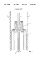
- FIG. 2 shows a diagrammatic sectional view of an improved arrangement of the prior art where the receiver coil is cooled from the inside and directly by the cryogenic agent flowing through it;
- FIG. 3a shows a diagrammatic sectional view of one embodiment of the RF receiver coil arrangement according to the invention.
- FIG. 3b shows an embodiment of the RF-receiver coil in the form of an electrically conducting layer applied on a substrate
- FIG. 3c shows an RF-receiver coil with thermal contact in the coil centre
- FIG. 3d shows the sealing of the "hot” connection of the RF-coil
- FIG. 3e shows the coupling of the coil by means of a dielectric partition
- FIG. 3f shows an arrangement with a cooled emitter/decoupler coil (schematic representation without taking the angular relation into consideration);
- FIG. 4 shows a schematic sectional view of an arrangement which is cooled by means of a cooled transfer line
- FIG. 5 shows a schematic sectional view of an arrangement with cooling by means of an integrated supply container for the cryogenic liquid
- FIG. 6 shows a schematic sectional view of an arrangement, wherein the platform is cooled by means of a metal block which is, at the other end, in contact with the cryogenic liquid of the supply container;
- FIG. 7 shows a schematic view of an arrangement wherein the platform is cooled by means of a cryocooler.
- the signal-to-noise ratio is considerably improved if the RF receiver coil is maintained at a substantially lower temperature, for example at 77 K (temperature of nitrogen) or 4.2 K (temperature of helium).
- 77 K temperature of nitrogen
- 4.2 K temperature of helium
- the sample 1 is positioned in the homogeneous field of the magnet 2, and is surrounded by the RF receiver coil 3, the latter being arranged in a glass Dewar which is filled with a cryogenic liquid 5 (such as nitrogen or helium) and which displays a double-walled structure with a vacuum 6 enclosed between the two walls.
- a cryogenic liquid 5 such as nitrogen or helium
- the spacing between the sample 1 and the RF receiver coil 3 is increased at least by the thickness of the two glass walls plus the dimension of the vacuum enclosed therebetween, so that the space factor is reduced significantly relative to its possible optimum.
- any bubbles that may possibly rise in the cryogenic liquid 5 may excite vibrations in the RF receiver coil 3, which in turn also impair the measuring result.
- FIG. 2 A better utilization of space and, thus, an improved space factor can be achieved by the prior-art arrangement illustrated in FIG. 2, where a hollow RF receiver coil 13 displaying the shape of a bent tube is passed by the cryogenic liquid 5 and is thereby cooled internally.
- the hollow RF receiver coil 13 being arranged in the vacuum, there is no need for the two glass walls of the glass Dewar 4 illustrated in FIG. 1.
- this arrangement is connected with the general disadvantage that it considerably restricts the designer's freedom with respect to the structure of the hollow RF receiver coil 13. This applies in particular to the shaping of the tube and, thus, to the geometry of the hollow RF receiver coil 13, Which is subject to very strict limitations. It is, therefore, not possible with this arrangement, which besides is extremely difficult to produce, to achieve an optimum space factor.
- the RF receiver coil 3 is likewise arranged in the vacuum 6 so that only one partition wall is required between the coil and the sample 1, as is illustrated in FIG. 3a .
- the RF receiver coil 3 is not cooled internally, but is in thermal contact with a cooled platform 7, or in the case of the illustrated embodiment with a cooling finger 8 projecting from the platform 7.
- the platform 7 is cooled by a heat exchanger 9 which is passed by the cryogenic liquid 5.
- the outer wall 10 of the resonator space too, is in thermal contact with the cooled platform 7 and is, consequently, also at low temperature.
- the measuring head 14 and the sample 1 are introduced into the homogeneous field of a magnet 2.
- the sample 1 rotates on a compressed-air cushion at room temperature.
- the temperature of the sample 1 is maintained, and if necessary regulated, by means of a gas flow which flows around the sample 1 and is supplied through a line 15 inside the measuring head 14 and wall 30.
- the cold screening of the resonator space leads to a high Q factor of the resonant circuit and reduces in addition the noise component contributed by the screening.
- the RF receiver coil 3 is heated up only by approx. 1 K by the heat radiated from the sample, which is kept at room temperature, and the resulting heat flow.
- Direct cooling of the RF receiver coil 3 is effected along the connections, in the embodiment illustrated in FIG. 3a.
- the coil is designed in such a way as to provide a defined, RF-wise "cold" connection in the coil center, being directly connected to the cooling finger 8.
- the RF receiver coil 3 consists of a metal wire of very high electric and thermal conductivity, which may in particular consist in part of high-purity aluminium, copper or silver, while the cooled platform 7 and the cooling finger 8 projecting therefrom consist of a solid copper block.
- the RF receiver coil 3 consists of an electrically conductive layer 17, in particular a superconductive layer, such as NbTi, applied on a substrate 16.
- the substrate may consist of a sapphire tube forming the cooled platform 7, either alone or in combination with an attached copper block.
- a connection of the RF receiver coil 3, 29 is guided through a bore in the platform 7, without any contact with the cooled platform 7, and is cooled by the platform 7 indirectly. Efficient cooling of the RF-wise "hot" connection 20, 26 can be achieved additionally, however, when the connection 20, 26 is coupled to the platform 7 by means of a dielectric 23 of high thermal conductivity, such as sapphire (See FIG. 3e).
- the annular gap between the bore 18 and the connection 26 passing therethrough may be sealed by an electrically non-conductive material 19 for example a powder metal bushing.
- the seal in the area of the heat exchanger 9 then defines a space which is sealed off from the vacuum 6 and which, when liquid helium is used for cooling, may accommodate the volatilizing helium return gas 25 which then surrounds, and helps cool, the connection 24 of the RF receiver coil 3 passing through the bushing. If the bushing is made from a dielectric of high thermal conductivity, this leads to even more efficient cooling of the "hot" connection 26.
- the losses in cooling agent during cooled operation of the system are of particular importance. If liquid nitrogen is employed for cooling the system, the liquid nitrogen consumption is relatively moderate, and quite acceptable under the aspects of price and handling. However, if the RF receiver coil 3 is to be cooled down to a lower temperature it may be necessary to use liquid helium for cooling.
- the component of the receiver system that must be cooled most efficiently is the RF receiver coil 3 as such. Its temperature should be close to 4.2 K. From this it follows that the coil 3 cannot be cooled using the enthalpy of the gaseous return flow of helium, but that the entire cooling capacity must be covered by the heat of evaporation of the liquid helium. It is, therefore, important that the heat input be kept at a minimum if the RF receiver coil 3 is to be cooled to temperatures near the helium temperature. If in case of the arrangement according to the invention cooling is not required for an entire glass Dewar 4, but only for the RF receiver coil as such, only the latter is exposed to direct room temperature radiation.
- the rest of the system is protected by one or more radiation shields 11, as described above, and is anyway much less critical for the heat balance, due to the T 4 (The Stefan-Boltzmann Law generally applicable to black body radiation) law.
- T 4 The Stefan-Boltzmann Law generally applicable to black body radiation
- a gallium-arsenide pre-amplifier is operated at helium temperature
- an additional thermal load results from the latter's dissipated power, which is in the range of 20 mW.
- cooling of the pre-amplifier 22 can be effected also, practically free of cost, using the enthalpy of the return flow of the helium gas which has been used for cooling the receiver coil. The same applies, with certain restrictions, with respect to the maximum operating temperature if a SQUID pre-amplifier is employed.
- cryostat Radiation, heat conduction along structural components, heat conduction along the RF coaxial cables and the power supply cables, etc.
- the cryostat is a flow-type cryostat in the form of a usual measuring head 14 which is introduced into the magnet from below.
- the flow-type cryostat 31 is continuously connected to the helium supply Dewar 33 by its transfer line 32.
- the continuously connected transfer line presents the link with the least efficient insulation in the described cooling arrangement.
- the losses encountered in the transfer line would dominate all other losses. Consequently, the transfer lines of this embodiment of the invention are likewise cooled by the return flow of the helium gas 25 so that the helium losses that have to be expected due to the transfer lines are in the range of approximately 1 liter per hour only.
- a measuring head 14 With flow-type cooling can be operated with helium losses of approx. 2 liters per hour. Consequently, a helium tank with a capacity of 100 liters would be sufficient for one Work's operation, provided the system is operated during the day only.
- the resulting costs have to be weighed against the enormous increase in efficiency of such a system which more than compensates the additional expense of the liquid helium.
- the described measuring head 14 With flow-type cooling distinguishes itself by relatively simple handling, its consumption of liquid helium only during actual measuring times, its easy service and its simple structure.
- the compact design of the arrangement also permits its use in the relatively small magnet bore of a high-field magnet.
- the measuring head 14 and wall 34 is equipped with an integrated supply vessel 35 with column 37 for liquid helium 36, whereby the helium consumption can be reduced in continuous operation.
- the cooling system is designed as cryocooler 38 with a closed cooling circuit, whereby an integrated helium recovery and, if desired, liquifying system is rendered possible.
Abstract
Description
Claims (27)
Applications Claiming Priority (2)
| Application Number | Priority Date | Filing Date | Title |
|---|---|---|---|
| DE4013111A DE4013111C2 (en) | 1990-04-25 | 1990-04-25 | RF receiver coil arrangement for NMR spectrometers |
| DE4013111 | 1990-04-25 |
Publications (1)
| Publication Number | Publication Date |
|---|---|
| US5247256A true US5247256A (en) | 1993-09-21 |
Family
ID=6405017
Family Applications (1)
| Application Number | Title | Priority Date | Filing Date |
|---|---|---|---|
| US07/690,499 Expired - Lifetime US5247256A (en) | 1990-04-25 | 1991-04-24 | Rf receiver coil arrangement for nmr spectrometers |
Country Status (4)
| Country | Link |
|---|---|
| US (1) | US5247256A (en) |
| EP (1) | EP0453834A1 (en) |
| JP (1) | JPH04230880A (en) |
| DE (1) | DE4013111C2 (en) |
Cited By (52)
| Publication number | Priority date | Publication date | Assignee | Title |
|---|---|---|---|---|
| US5508613A (en) * | 1994-08-29 | 1996-04-16 | Conductus, Inc. | Apparatus for cooling NMR coils |
| US5517856A (en) * | 1994-05-11 | 1996-05-21 | Bruker Analytische Messtechnik Gmbh | NMR sample holder |
| US5565778A (en) * | 1992-06-01 | 1996-10-15 | Conductus, Inc. | Nuclear magnetic resonance probe coil |
| US5585723A (en) * | 1995-03-23 | 1996-12-17 | Conductus, Inc. | Inductively coupled superconducting coil assembly |
| US5594342A (en) * | 1992-06-01 | 1997-01-14 | Conductus, Inc. | Nuclear magnetic resonance probe coil with enhanced current-carrying capability |
| EP0782005A1 (en) * | 1995-12-20 | 1997-07-02 | Spectrospin Ag | Probe head for an NMR spectrometer |
| US5689187A (en) * | 1995-03-25 | 1997-11-18 | Spectrospin Ag | RF receiver coil configuration for an NMR spectrometer |
| US5889456A (en) * | 1997-05-16 | 1999-03-30 | Spectrospin Ag | NMR measuring device having a cooled probe head |
| US6065630A (en) * | 1998-12-08 | 2000-05-23 | The United States Of America As Represented By The United States Department Of Energy | Sapphire tube pressure vessel |
| DE10006323C1 (en) * | 2000-02-12 | 2001-08-09 | Bruker Ag Faellanden | Cooled NMR probe head with uniform temperature control of the test sample |
| DE10006324C1 (en) * | 2000-02-12 | 2001-08-16 | Bruker Ag Faellanden | Cooled NMR probe head with device for centering the measurement sample |
| DE10006317C1 (en) * | 2000-02-12 | 2001-08-16 | Bruker Ag Faellanden | Cooled NMR probe head with thermal insulation of the sample |
| US6411092B1 (en) | 2000-09-30 | 2002-06-25 | Varian, Inc. | Clad metal foils for low temperature NMR probe RF coils |
| US6563314B1 (en) | 1999-02-10 | 2003-05-13 | Schlumberger Technology Corporation | Well logging method and apparatus for determining the nuclear magnetic resonance longitudinal magnetization decay of formations |
| US20030098689A1 (en) * | 2001-11-27 | 2003-05-29 | Bruker Biospinag | Stabilization of transverse magnetization in superconducting NMR resonators |
| WO2003079034A3 (en) * | 2002-03-15 | 2003-12-18 | Bruker Biospin Corp | Flow-through cryogenic nmr probe |
| US20030231019A1 (en) * | 2002-06-12 | 2003-12-18 | Bruker Biospin Ag | Device for precise centering of an MMR sample tube |
| US20040113617A1 (en) * | 2002-12-17 | 2004-06-17 | De Swiet Thomas | Radio frequency NMR resonator with split axial shields |
| WO2004099805A1 (en) * | 2003-05-09 | 2004-11-18 | The University Of Hong Kong | High temperature superconductor tape rf coil for magnetic resonance imaging |
| EP1435525A3 (en) * | 2003-01-06 | 2004-11-24 | Jeol Ltd. | Cooled NMR probe |
| US20040251902A1 (en) * | 2003-06-10 | 2004-12-16 | Kazumasa Takagi | Nuclear magnetic resonance equipment |
| US20050052184A1 (en) * | 2003-09-09 | 2005-03-10 | Haner Ronald L. | Radially-compact NMR flow cell assemblies and methods |
| US20050068034A1 (en) * | 2003-09-30 | 2005-03-31 | Hiroshi Morita | Nuclear magnetic resonance measuring apparatus |
| US20050202976A1 (en) * | 2001-09-06 | 2005-09-15 | Neil Killoran | Apparatus for use in nmr system |
| US20060006869A1 (en) * | 2004-05-25 | 2006-01-12 | Jeol Ltd. | NMR detector and NMR spectrometer |
| US20060033498A1 (en) * | 2004-08-11 | 2006-02-16 | Kazuo Saitoh | Nuclear magnetic resonance apparatus |
| US20060055407A1 (en) * | 2004-03-02 | 2006-03-16 | Hisaaki Ochi | Nuclear magnetic resonance system |
| US20060119360A1 (en) * | 2004-12-08 | 2006-06-08 | Hitachi, Ltd. | NMR spectrometer and NMR probe |
| US20060130493A1 (en) * | 2004-12-17 | 2006-06-22 | Bruker Biospin Gmbh | NMR spectrometer with common refrigerator for cooling an NMR probe head and cryostat |
| US20060132134A1 (en) * | 2004-12-22 | 2006-06-22 | General Electric Company | Cryogenically cooled radiofrequency coil array for magnetic resonance imaging |
| US20070139046A1 (en) * | 2005-12-17 | 2007-06-21 | Bruker Biospin Mri Gmbh | NMR probe head with heated housing |
| US20070202059A1 (en) * | 2006-02-01 | 2007-08-30 | Premier Dental Products Company | Stable one-part aqueous tooth whitening composition |
| US20080084211A1 (en) * | 2006-10-04 | 2008-04-10 | Nicolas Freytag | Vacuum container for cooled magnetic resonance probe head |
| US20080111548A1 (en) * | 2006-11-09 | 2008-05-15 | Hiroyuki Yamamoto | Nmr probe and nmr spectrometer |
| EP1953560A2 (en) * | 2007-02-01 | 2008-08-06 | Bruker Biospin Corp. | Nuclear magnetic resonance probe with cooled sample coil |
| US20080231277A1 (en) * | 2007-03-23 | 2008-09-25 | Hiroyuki Yamamoto | NMR spectrometer |
| US20090021255A1 (en) * | 2004-11-23 | 2009-01-22 | M2M Imaging Corp. | Apparatus and method for cryogenically cooling a coil on a magnetic resonance imaging system |
| US20090322333A1 (en) * | 2006-08-17 | 2009-12-31 | Kabushiki Kaisha Kobe Seiko Sho (Kobe Steel, Ltd.) | Cooled NMR Probe Head And NMR Analyzer |
| US20100079143A1 (en) * | 2008-09-30 | 2010-04-01 | Burns Sean T | Demountable cryogenic nmr connection assembly systems and methods |
| US20100321018A1 (en) * | 2009-06-19 | 2010-12-23 | Jeol Ltd. | High-Resolution NMR Probe |
| US20110100027A1 (en) * | 2009-11-03 | 2011-05-05 | Schnell Marc A | Cooling device for cryogenic cooling of an NMR detection system with the assistance of a container filled with a cryogenic fluid |
| US20120092013A1 (en) * | 2010-07-12 | 2012-04-19 | Bruker Biospin Corporation | Nmr reaction monitoring flow cell |
| DE102011005888A1 (en) | 2011-03-22 | 2012-09-27 | Bruker Biospin Ag | Cooling of a Cryo Probe Head in a Magnetic Resonance Resonance Equipment |
| US20130091870A1 (en) * | 2011-10-17 | 2013-04-18 | Bruker Biospin | Cold gas supply device and NMR installation comprising such a device |
| US8455841B2 (en) | 2009-06-30 | 2013-06-04 | Hitachi High-Technologies Corporation | Ion microscope |
| US20140055138A1 (en) * | 2012-08-23 | 2014-02-27 | Jeol Resonance Inc. | NMR Detection Module |
| US20140091800A1 (en) * | 2012-09-28 | 2014-04-03 | Schlumberger Technology Corporation | Nmr sample containment |
| FR2998377A1 (en) * | 2012-11-16 | 2014-05-23 | Bruker Biospin Ag | ELECTRONIC CIRCUIT FOR MAGNETIC RESONANCE APPARATUS AND METHOD OF OPERATION |
| EP3561533A1 (en) | 2018-04-26 | 2019-10-30 | Jeol Ltd. | Nmr probe |
| US20200096581A1 (en) * | 2018-09-24 | 2020-03-26 | Shahin Pourrahimi | Integrated single-sourced cooling of superconducting magnets and rf coils in nuclear magnetic resonance devices |
| CN115112703A (en) * | 2022-08-29 | 2022-09-27 | 华中科技大学 | Non-discharge sample rod in low-temperature NMR measurement system |
| US11508498B2 (en) | 2019-11-26 | 2022-11-22 | Trimtabs Ltd | Cables and methods thereof |
Families Citing this family (14)
| Publication number | Priority date | Publication date | Assignee | Title |
|---|---|---|---|---|
| EP0532966A1 (en) * | 1991-09-16 | 1993-03-24 | Bruker Instruments, Inc. | Improved NMR probe for imaging small samples |
| DE4408195C2 (en) * | 1994-03-11 | 1996-09-05 | Bruker Analytische Messtechnik | Magnetic resonance resonator |
| US5552709A (en) * | 1995-10-17 | 1996-09-03 | Varian Associates, Inc. | NMR sample cell |
| DE19648253C2 (en) * | 1996-11-22 | 2002-04-04 | Siemens Ag | Pulse tube cooler and use of the same |
| DE19722387C2 (en) * | 1997-05-28 | 1999-11-11 | Siemens Ag | Antenna for a magnetic resonance device |
| JP4317646B2 (en) * | 2000-06-26 | 2009-08-19 | 独立行政法人理化学研究所 | Nuclear magnetic resonance apparatus |
| JP4150825B2 (en) * | 2003-03-31 | 2008-09-17 | 独立行政法人理化学研究所 | NMR probe |
| JP2005172597A (en) * | 2003-12-10 | 2005-06-30 | Hitachi Ltd | Nuclear magnetic resonance measurement apparatus |
| JP4309854B2 (en) | 2005-01-20 | 2009-08-05 | 株式会社日立製作所 | Low temperature probe and nuclear magnetic resonance analyzer using the same |
| JP4755652B2 (en) * | 2005-10-25 | 2011-08-24 | 株式会社日立製作所 | Nuclear magnetic resonance probe and nuclear magnetic resonance apparatus |
| JP4851265B2 (en) * | 2006-08-24 | 2012-01-11 | 株式会社神戸製鋼所 | Cooled NMR probe head and NMR analyzer equipped with the same |
| JP5999599B2 (en) * | 2012-12-28 | 2016-09-28 | 日本電子株式会社 | probe |
| JP6007438B2 (en) * | 2012-12-28 | 2016-10-12 | 日本電子株式会社 | Cryogen supply equipment |
| JP6127799B2 (en) * | 2013-07-23 | 2017-05-17 | 三菱電機株式会社 | Superconducting coil drive system |
Citations (4)
| Publication number | Priority date | Publication date | Assignee | Title |
|---|---|---|---|---|
| US3826972A (en) * | 1973-08-17 | 1974-07-30 | Univ Leland Stanford Junior | Method and apparatus for detecting nuclear magnetic resonance |
| JPS55131758A (en) * | 1979-03-30 | 1980-10-13 | Jeol Ltd | Nmr probe |
| US4240033A (en) * | 1979-03-26 | 1980-12-16 | Varian Associates, Inc. | Method and apparatus for preventing ionization induced noise in decoupler experiments |
| EP0303095A2 (en) * | 1987-08-04 | 1989-02-15 | Bruker Analytische Messtechnik GmbH | Antenna for NMR spectrometer |
-
1990
- 1990-04-25 DE DE4013111A patent/DE4013111C2/en not_active Revoked
-
1991
- 1991-04-04 EP EP91105315A patent/EP0453834A1/en not_active Withdrawn
- 1991-04-24 US US07/690,499 patent/US5247256A/en not_active Expired - Lifetime
- 1991-04-25 JP JP3095531A patent/JPH04230880A/en active Pending
Patent Citations (4)
| Publication number | Priority date | Publication date | Assignee | Title |
|---|---|---|---|---|
| US3826972A (en) * | 1973-08-17 | 1974-07-30 | Univ Leland Stanford Junior | Method and apparatus for detecting nuclear magnetic resonance |
| US4240033A (en) * | 1979-03-26 | 1980-12-16 | Varian Associates, Inc. | Method and apparatus for preventing ionization induced noise in decoupler experiments |
| JPS55131758A (en) * | 1979-03-30 | 1980-10-13 | Jeol Ltd | Nmr probe |
| EP0303095A2 (en) * | 1987-08-04 | 1989-02-15 | Bruker Analytische Messtechnik GmbH | Antenna for NMR spectrometer |
Non-Patent Citations (14)
| Title |
|---|
| Hoult et al., Journal of Magnetic Resonance 24, 71 85 (1976). * |
| Hoult et al., Journal of Magnetic Resonance 24, 71-85 (1976). |
| Review of Scientific Instruments, vol. 36, No. 10, 1965, New York US, pp. 1509 1510 S. Meiboom, R. C. Hewitt: High Resolution NMR Probe Suitable for Use in a Superconducting Solenoid . * |
| Review of Scientific Instruments, vol. 36, No. 10, 1965, New York US, pp. 1509-1510 S. Meiboom, R. C. Hewitt: "High Resolution NMR Probe Suitable for Use in a Superconducting Solenoid". |
| Review of Scientific Instruments, vol. 55, No. 1, Jan. 1984, New York US, pp. 68 74 K. Carduner et al.: Variable temperature solid state nuclear magnetic resoance probe for superconducting magnets . . . . * |
| Review of Scientific Instruments, vol. 55, No. 1, Jan. 1984, New York US, pp. 68-74 K. Carduner et al.: "Variable-temperature solid-state nuclear-magnetic-resoance probe for superconducting magnets . . . ". |
| Review of Scientific Instruments, vol. 57, No. 3, Mar. 1986, New York US, pp. 404 409 M. G. Richards et al.: Cryogenic GaAs FET amplifiers and their Use in NMR detection . * |
| Review of Scientific Instruments, vol. 57, No. 3, Mar. 1986, New York US, pp. 404-409 M. G. Richards et al.: "Cryogenic GaAs FET amplifiers and their Use in NMR detection". |
| Review of Scientific Instruments, vol. 57, No. 3, Mar. 1986, New York US, pp. 410 413 L. J. Friedman et al.: Direct detection of low frequency NMR using a dc SQUID . * |
| Review of Scientific Instruments, vol. 57, No. 3, Mar. 1986, New York US, pp. 410-413 L. J. Friedman et al.: "Direct detection of low-frequency NMR using a dc SQUID". |
| Styles et al., Journal of Magnetic Resonance 60, 397 404 (1984). * |
| Styles et al., Journal of Magnetic Resonance 60, 397-404 (1984). |
| Styles et al., Journal of Magnetic Resonance 84, 376 378 (1989). * |
| Styles et al., Journal of Magnetic Resonance 84, 376-378 (1989). |
Cited By (94)
| Publication number | Priority date | Publication date | Assignee | Title |
|---|---|---|---|---|
| US5565778A (en) * | 1992-06-01 | 1996-10-15 | Conductus, Inc. | Nuclear magnetic resonance probe coil |
| US5594342A (en) * | 1992-06-01 | 1997-01-14 | Conductus, Inc. | Nuclear magnetic resonance probe coil with enhanced current-carrying capability |
| US5517856A (en) * | 1994-05-11 | 1996-05-21 | Bruker Analytische Messtechnik Gmbh | NMR sample holder |
| US5508613A (en) * | 1994-08-29 | 1996-04-16 | Conductus, Inc. | Apparatus for cooling NMR coils |
| US5585723A (en) * | 1995-03-23 | 1996-12-17 | Conductus, Inc. | Inductively coupled superconducting coil assembly |
| US5689187A (en) * | 1995-03-25 | 1997-11-18 | Spectrospin Ag | RF receiver coil configuration for an NMR spectrometer |
| EP0782005A1 (en) * | 1995-12-20 | 1997-07-02 | Spectrospin Ag | Probe head for an NMR spectrometer |
| US5814992A (en) * | 1995-12-20 | 1998-09-29 | Spectrospin Ag | NMR probe head with cryogenically cooled preampifiers |
| US5889456A (en) * | 1997-05-16 | 1999-03-30 | Spectrospin Ag | NMR measuring device having a cooled probe head |
| US6065630A (en) * | 1998-12-08 | 2000-05-23 | The United States Of America As Represented By The United States Department Of Energy | Sapphire tube pressure vessel |
| US6563314B1 (en) | 1999-02-10 | 2003-05-13 | Schlumberger Technology Corporation | Well logging method and apparatus for determining the nuclear magnetic resonance longitudinal magnetization decay of formations |
| DE10006317C1 (en) * | 2000-02-12 | 2001-08-16 | Bruker Ag Faellanden | Cooled NMR probe head with thermal insulation of the sample |
| US6437570B2 (en) | 2000-02-12 | 2002-08-20 | Bruker Biospin Ag | Cooled NMR probe head with uniform temperature control of the sample |
| US6441617B2 (en) | 2000-02-12 | 2002-08-27 | Bruker Biospin Ag | Cooled NMR probe head with thermal insulation of the sample |
| US6466019B2 (en) | 2000-02-12 | 2002-10-15 | Bruker Biospin Ag | Cooled NMR probe head comprising a device for centering the sample |
| DE10006324C1 (en) * | 2000-02-12 | 2001-08-16 | Bruker Ag Faellanden | Cooled NMR probe head with device for centering the measurement sample |
| DE10006323C1 (en) * | 2000-02-12 | 2001-08-09 | Bruker Ag Faellanden | Cooled NMR probe head with uniform temperature control of the test sample |
| US6411092B1 (en) | 2000-09-30 | 2002-06-25 | Varian, Inc. | Clad metal foils for low temperature NMR probe RF coils |
| US20050202976A1 (en) * | 2001-09-06 | 2005-09-15 | Neil Killoran | Apparatus for use in nmr system |
| US6833701B2 (en) * | 2001-11-27 | 2004-12-21 | Bruker Biospin Ag | Stabilization of transverse magnetization in superconducting NMR resonators |
| US20030098689A1 (en) * | 2001-11-27 | 2003-05-29 | Bruker Biospinag | Stabilization of transverse magnetization in superconducting NMR resonators |
| WO2003079034A3 (en) * | 2002-03-15 | 2003-12-18 | Bruker Biospin Corp | Flow-through cryogenic nmr probe |
| US20040004478A1 (en) * | 2002-03-15 | 2004-01-08 | Bruker Biospin Corporation | Flow-through cryogenic NMR probe |
| US6838880B2 (en) * | 2002-03-15 | 2005-01-04 | Bruker Biospin Corporation | Flow-through cryogenic NMR probe |
| US20030231019A1 (en) * | 2002-06-12 | 2003-12-18 | Bruker Biospin Ag | Device for precise centering of an MMR sample tube |
| US6867594B2 (en) * | 2002-06-12 | 2005-03-15 | Bruker Biospin Ag | Device for precise centering of an NMR sample tube |
| US20040113617A1 (en) * | 2002-12-17 | 2004-06-17 | De Swiet Thomas | Radio frequency NMR resonator with split axial shields |
| US6812703B2 (en) * | 2002-12-17 | 2004-11-02 | Varian, Inc. | Radio frequency NMR resonator with split axial shields |
| EP1435525A3 (en) * | 2003-01-06 | 2004-11-24 | Jeol Ltd. | Cooled NMR probe |
| WO2004099805A1 (en) * | 2003-05-09 | 2004-11-18 | The University Of Hong Kong | High temperature superconductor tape rf coil for magnetic resonance imaging |
| US20040251902A1 (en) * | 2003-06-10 | 2004-12-16 | Kazumasa Takagi | Nuclear magnetic resonance equipment |
| US6958608B2 (en) | 2003-06-10 | 2005-10-25 | Hitachi, Ltd. | Nuclear magnetic resonance equipment |
| US20050052184A1 (en) * | 2003-09-09 | 2005-03-10 | Haner Ronald L. | Radially-compact NMR flow cell assemblies and methods |
| US6972568B2 (en) * | 2003-09-09 | 2005-12-06 | Varian, Inc. | Radially-compact NMR flow cell assemblies and methods |
| US20050068034A1 (en) * | 2003-09-30 | 2005-03-31 | Hiroshi Morita | Nuclear magnetic resonance measuring apparatus |
| US20060038567A1 (en) * | 2003-09-30 | 2006-02-23 | Hiroshi Morita | Nuclear magnetic resonance measuring apparatus |
| US7030613B2 (en) * | 2003-09-30 | 2006-04-18 | Hitachi, Ltd. | Nuclear magnetic resonance measuring apparatus |
| US7126335B2 (en) | 2003-09-30 | 2006-10-24 | Hitachi, Ltd. | Nuclear magnetic resonance measuring apparatus |
| US20060055407A1 (en) * | 2004-03-02 | 2006-03-16 | Hisaaki Ochi | Nuclear magnetic resonance system |
| US7141975B2 (en) | 2004-03-02 | 2006-11-28 | Hitachi, Ltd. | Nuclear magnetic resonance system |
| US20060006869A1 (en) * | 2004-05-25 | 2006-01-12 | Jeol Ltd. | NMR detector and NMR spectrometer |
| US7180295B2 (en) * | 2004-05-25 | 2007-02-20 | Jeol Ltd. | NMR detector and NMR spectrometer equipped therewith |
| US7173424B2 (en) | 2004-08-11 | 2007-02-06 | Hitachi, Ltd. | Nuclear magnetic resonance apparatus |
| US20060033498A1 (en) * | 2004-08-11 | 2006-02-16 | Kazuo Saitoh | Nuclear magnetic resonance apparatus |
| US20100280361A1 (en) * | 2004-11-23 | 2010-11-04 | M2M Imaging Corp. | Apparatus and method for cryogenically cooling a coil on a magnetic resonance imaging system |
| US20090021255A1 (en) * | 2004-11-23 | 2009-01-22 | M2M Imaging Corp. | Apparatus and method for cryogenically cooling a coil on a magnetic resonance imaging system |
| US8115487B2 (en) | 2004-11-23 | 2012-02-14 | m2m Imaging Corporation | Apparatus and method for cryogenically cooling a coil on a magnetic resonance imaging system |
| US7759935B2 (en) * | 2004-11-23 | 2010-07-20 | M2M Imaging Corp. | Apparatus and method for cryogenically cooling a coil on a magnetic resonance imaging system |
| US7138801B2 (en) | 2004-12-08 | 2006-11-21 | Hitachi, Ltd. | NMR spectrometer and NMR probe |
| US20060119360A1 (en) * | 2004-12-08 | 2006-06-08 | Hitachi, Ltd. | NMR spectrometer and NMR probe |
| US20060130493A1 (en) * | 2004-12-17 | 2006-06-22 | Bruker Biospin Gmbh | NMR spectrometer with common refrigerator for cooling an NMR probe head and cryostat |
| US7430872B2 (en) * | 2004-12-17 | 2008-10-07 | Bruker Biospin Gmbh | NMR spectrometer with common refrigerator for cooling an NMR probe head and cryostat |
| US7167000B2 (en) * | 2004-12-22 | 2007-01-23 | General Electric Company | Cryogenically cooled radiofrequency coil array for magnetic resonance imaging |
| US20060132134A1 (en) * | 2004-12-22 | 2006-06-22 | General Electric Company | Cryogenically cooled radiofrequency coil array for magnetic resonance imaging |
| US20070139046A1 (en) * | 2005-12-17 | 2007-06-21 | Bruker Biospin Mri Gmbh | NMR probe head with heated housing |
| US7358735B2 (en) * | 2005-12-17 | 2008-04-15 | Bruker Biospin Mri Gmbh | NMR probe head with heated housing |
| US20070202059A1 (en) * | 2006-02-01 | 2007-08-30 | Premier Dental Products Company | Stable one-part aqueous tooth whitening composition |
| US20090322333A1 (en) * | 2006-08-17 | 2009-12-31 | Kabushiki Kaisha Kobe Seiko Sho (Kobe Steel, Ltd.) | Cooled NMR Probe Head And NMR Analyzer |
| US7990148B2 (en) | 2006-08-17 | 2011-08-02 | Kobe Steel Ltd. | Cooled NMR probe head and NMR analyzer |
| US7514922B2 (en) | 2006-10-04 | 2009-04-07 | Bruker Biospin Ag | Vacuum container for cooled magnetic resonance probe head |
| DE102006046888B4 (en) * | 2006-10-04 | 2010-12-16 | Bruker Biospin Ag | Cooled magnetic resonance probe head with a vacuum container and associated NMR measuring apparatus |
| US20080084211A1 (en) * | 2006-10-04 | 2008-04-10 | Nicolas Freytag | Vacuum container for cooled magnetic resonance probe head |
| US7619414B2 (en) | 2006-11-09 | 2009-11-17 | Hitachi, Ltd. | NMR probe and NMR spectrometer |
| US20080111548A1 (en) * | 2006-11-09 | 2008-05-15 | Hiroyuki Yamamoto | Nmr probe and nmr spectrometer |
| EP1953560A3 (en) * | 2007-02-01 | 2009-02-11 | Bruker Biospin Corp. | Nuclear magnetic resonance probe with cooled sample coil |
| EP1953560A2 (en) * | 2007-02-01 | 2008-08-06 | Bruker Biospin Corp. | Nuclear magnetic resonance probe with cooled sample coil |
| US20080231277A1 (en) * | 2007-03-23 | 2008-09-25 | Hiroyuki Yamamoto | NMR spectrometer |
| US20100079143A1 (en) * | 2008-09-30 | 2010-04-01 | Burns Sean T | Demountable cryogenic nmr connection assembly systems and methods |
| US7812606B2 (en) * | 2008-09-30 | 2010-10-12 | Varian, Inc. | Demountable cryogenic NMR connection assembly systems and methods |
| US20100321018A1 (en) * | 2009-06-19 | 2010-12-23 | Jeol Ltd. | High-Resolution NMR Probe |
| US8013608B2 (en) * | 2009-06-19 | 2011-09-06 | Jeol Resonance Inc. | High-resolution NMR probe |
| US8455841B2 (en) | 2009-06-30 | 2013-06-04 | Hitachi High-Technologies Corporation | Ion microscope |
| US20110100027A1 (en) * | 2009-11-03 | 2011-05-05 | Schnell Marc A | Cooling device for cryogenic cooling of an NMR detection system with the assistance of a container filled with a cryogenic fluid |
| US20120092013A1 (en) * | 2010-07-12 | 2012-04-19 | Bruker Biospin Corporation | Nmr reaction monitoring flow cell |
| US9448192B2 (en) * | 2010-07-12 | 2016-09-20 | Bruker Biospin Corporation | NMR reaction monitoring flow cell |
| US8686729B2 (en) * | 2010-07-12 | 2014-04-01 | Bruker Biospin Corporation | NMR reaction monitoring flow cell |
| US8975896B2 (en) * | 2011-03-22 | 2015-03-10 | Bruker Biospin Ag | Cryogenic probehead cooler in a nuclear magnetic resonance apparatus |
| DE102011005888B4 (en) * | 2011-03-22 | 2014-01-09 | Bruker Biospin Ag | Cooling of a Cryo Probe Head in a Magnetic Resonance Resonance Equipment |
| US20120242335A1 (en) * | 2011-03-22 | 2012-09-27 | Oskar Schett | Cryogenic probehead cooler in a nuclear magnetic resonance apparatus |
| DE102011005888A1 (en) | 2011-03-22 | 2012-09-27 | Bruker Biospin Ag | Cooling of a Cryo Probe Head in a Magnetic Resonance Resonance Equipment |
| US20130091870A1 (en) * | 2011-10-17 | 2013-04-18 | Bruker Biospin | Cold gas supply device and NMR installation comprising such a device |
| US10041629B2 (en) * | 2011-10-17 | 2018-08-07 | Bruker Biospin | Cold gas supply device and NMR installation comprising such a device |
| US20140055138A1 (en) * | 2012-08-23 | 2014-02-27 | Jeol Resonance Inc. | NMR Detection Module |
| US9372247B2 (en) * | 2012-08-23 | 2016-06-21 | Kyoto University | NMR detection module |
| US20140091800A1 (en) * | 2012-09-28 | 2014-04-03 | Schlumberger Technology Corporation | Nmr sample containment |
| US9606201B2 (en) | 2012-11-16 | 2017-03-28 | Bruker Biospin Ag | Electrical circuit in the magnetic field of an MR apparatus |
| FR2998377A1 (en) * | 2012-11-16 | 2014-05-23 | Bruker Biospin Ag | ELECTRONIC CIRCUIT FOR MAGNETIC RESONANCE APPARATUS AND METHOD OF OPERATION |
| EP3561533A1 (en) | 2018-04-26 | 2019-10-30 | Jeol Ltd. | Nmr probe |
| US10775456B2 (en) | 2018-04-26 | 2020-09-15 | Jeol Ltd. | NMR probe |
| US20200096581A1 (en) * | 2018-09-24 | 2020-03-26 | Shahin Pourrahimi | Integrated single-sourced cooling of superconducting magnets and rf coils in nuclear magnetic resonance devices |
| US11009572B2 (en) * | 2018-09-24 | 2021-05-18 | Shahin Pourrahimi | Integrated single-sourced cooling of superconducting magnets and RF coils in nuclear magnetic resonance devices |
| US11508498B2 (en) | 2019-11-26 | 2022-11-22 | Trimtabs Ltd | Cables and methods thereof |
| CN115112703A (en) * | 2022-08-29 | 2022-09-27 | 华中科技大学 | Non-discharge sample rod in low-temperature NMR measurement system |
| CN115112703B (en) * | 2022-08-29 | 2022-12-02 | 华中科技大学 | Non-discharge sample rod in low-temperature NMR measurement system |
Also Published As
| Publication number | Publication date |
|---|---|
| DE4013111A1 (en) | 1991-10-31 |
| DE4013111C2 (en) | 1994-05-26 |
| JPH04230880A (en) | 1992-08-19 |
| EP0453834A1 (en) | 1991-10-30 |
Similar Documents
| Publication | Publication Date | Title |
|---|---|---|
| US5247256A (en) | Rf receiver coil arrangement for nmr spectrometers | |
| US5508613A (en) | Apparatus for cooling NMR coils | |
| US5744959A (en) | NMR measurement apparatus with pulse tube cooler | |
| USRE33419E (en) | Cryostat assembly | |
| US5913888A (en) | Antenna device having at least one cooled antenna | |
| US7222490B2 (en) | NMR spectrometer with refrigerator cooling | |
| US5936499A (en) | Pressure control system for zero boiloff superconducting magnet | |
| US4498046A (en) | Room temperature cryogenic test interface | |
| EP2700970B1 (en) | NMR detection module | |
| US5623240A (en) | Compact superconducting magnet system free from liquid helium | |
| US20080150536A1 (en) | Cold normal metal and hts nmr probe coils with electric field shields | |
| US9958520B2 (en) | Introducing an NMR apparatus comprising cooled probe components via a vacuum lock | |
| US7514922B2 (en) | Vacuum container for cooled magnetic resonance probe head | |
| US20050202976A1 (en) | Apparatus for use in nmr system | |
| JP3711660B2 (en) | Open magnetic resonance imaging magnet | |
| Seifert | Liquid helium cooled sample stage for scanning electron microscope | |
| US6698224B2 (en) | Electronic apparatus having at least two electronic parts operating at different temperatures | |
| JPS6294769A (en) | Two-step thermal coupling | |
| CN1957429B (en) | Electrically conductive shield for refrigerator | |
| GB2434452A (en) | NMR probe head with heated housing | |
| JPH0620832A (en) | Conductor-bonded aggregate for super- conducting magnet | |
| US5072591A (en) | Flexible transfer line exhaust gas shield | |
| JPH10256027A (en) | Superconducting magnet system | |
| CN117062515B (en) | Heat shield device and Josephson junction array chip system | |
| Bonaldi et al. | The ultracryogenic gravitational wave antenna AURIGA |
Legal Events
| Date | Code | Title | Description |
|---|---|---|---|
| AS | Assignment |
Owner name: SPECTROSPIN AG, INDUSTRIESTRASSE A CORP. OF SWI Free format text: ASSIGNMENT OF ASSIGNORS INTEREST.;ASSIGNOR:MAREK, DANIEL;REEL/FRAME:005698/0346 Effective date: 19910411 |
|
| STCF | Information on status: patent grant |
Free format text: PATENTED CASE |
|
| FEPP | Fee payment procedure |
Free format text: PAYOR NUMBER ASSIGNED (ORIGINAL EVENT CODE: ASPN); ENTITY STATUS OF PATENT OWNER: LARGE ENTITY |
|
| FPAY | Fee payment |
Year of fee payment: 4 |
|
| FPAY | Fee payment |
Year of fee payment: 8 |
|
| AS | Assignment |
Owner name: BRUKER AG, GERMANY Free format text: CHANGE OF NAME;ASSIGNOR:SPECTROSPIN AG;REEL/FRAME:013552/0170 Effective date: 20020916 Owner name: BRUKER BIOSPIN AG, GERMANY Free format text: CHANGE OF NAME;ASSIGNOR:BRUKER AG;REEL/FRAME:013552/0164 Effective date: 20020916 |
|
| FPAY | Fee payment |
Year of fee payment: 12 |