US5257363A - Computer-aided generation of programs modelling complex systems using colored petri nets - Google Patents
Computer-aided generation of programs modelling complex systems using colored petri nets Download PDFInfo
- Publication number
- US5257363A US5257363A US07/507,119 US50711990A US5257363A US 5257363 A US5257363 A US 5257363A US 50711990 A US50711990 A US 50711990A US 5257363 A US5257363 A US 5257363A
- Authority
- US
- United States
- Prior art keywords
- arc
- input
- transition
- variables
- model
- Prior art date
- Legal status (The legal status is an assumption and is not a legal conclusion. Google has not performed a legal analysis and makes no representation as to the accuracy of the status listed.)
- Expired - Fee Related
Links
Images


Classifications
-
- G—PHYSICS
- G06—COMPUTING; CALCULATING OR COUNTING
- G06F—ELECTRIC DIGITAL DATA PROCESSING
- G06F30/00—Computer-aided design [CAD]
- G06F30/20—Design optimisation, verification or simulation
- G06F30/22—Design optimisation, verification or simulation using Petri net models
Definitions
- This invention relates to a method and apparatus for creating graphical models of complex systems (i.e., computer programs representing such systems), for checking those models for certain properties, and for executing those models to simulate such systems and control their operation. More particularly, the invention relates to a system for developing those models using a hierarchical arrangement of so-called "Colored" Petri Nets.
- Computer-graphical methods are being used more and more frequently in the specification and design of complex systems.
- the resulting models provide a basis for validating the design concepts, because they can be understood both by the designer and by the user, and because they can be scrutinized to determine whether the user's requirements have been satisfied.
- the model can then be used as a guide to, or vehicle for, the implementation or control of the actual physical system.
- a computer program implementing the model can be used to control the system operation.
- the system might, thus, be a telephone switching network and the program might operate the digital controller which, in turn, operates the switches.
- the system might be a subway traffic control system and the program might operate signal lights, dispatch scheduling, and so forth.
- Models of complex systems are now being introduced into practice. In general, they may be classified into two categories: (1) models based on an underlying mathematical framework and (2) models based on an ad hoc graphical representation tied to conventional programming languages. Both types of models can be executed and, in that sense, can be thought of as programs. Models of the first type, moreover, can be analyzed according to certain rules, to discover whether the system possesses certain behavioral properties. These properties include deadlock, safety, and some forms of invariance. Performance analysis is also possible in some cases.
- Petri nets have been very useful for modelling systems graphically and mathematically, and though theoretically they are useful for system analysis, as well, it has been found that there is a tradeoff between modeling generality and analysis capability. That is, the more general the model represented by the Petri net, the less amenable it is to analysis. Indeed, it has been said that the complexity problem is a major weakness of Petri nets; that is, Petri-net-based models become too large for analysis even for a modest size system. Moreover, Petri net models and models based on other such paradigms typically are not analyzable, though they are developed on sophisticated computer systems. Thus, they do not address details of behavior of the complex system which they model.
- Still another object of the invention is to provide a method for generating executable models of large complex systems from simpler models of parts of the system, i.e., subsystems.
- Yet another object of the invention is to generate models of complex systems which are analyzable, to permit detection of predetermined system behaviors or properties.
- a further object of the invention is to provide a method for graphically constructing executable models of systems, which are also analyzable.
- a programmed digital computer serving as a graphical "engine” is employed to construct an executable model for a complex system using a hierarchy of so-called “Colored” Petri nets (CPN's or CP-nets).
- CPN's or CP-nets Petri nets
- the operation of the complex system is specified in terms of a graphical net structure and formal net inscriptions, such as arc expressions and guards, which ensure development of a program, or executable model, and associated data structures, properly defining the system.
- Sophisticated syntax checks and other tools are provided for ensuring that the model so constructed conforms to a set of rules which guarantee valid system behavior.
- a model of the subject system is created.
- This model is built from a plurality of Colored Petri nets (CPN's or CP-nets) constituting submodels of parts of the system, the submodels being interrelated in a hierarchical fashion.
- CPN's or CP-nets Colored Petri nets
- the model, and the constituent submodels, are represented to the modeller on a video display terminal, or the like.
- the constructed model is actually a data base.
- a syntax check is performed.
- the syntax check validates the structure of the model, to ensure that all necessary occurrence functions can be generated. If the syntax check fails, indicating the model violates a prescribed rule, the modeller edits the model and again performs a syntax check. Now that the editting phase of the process is complete, the procedure "switches" into a simulation mode, commencing with the compilation of executable program code. Once the compiled code has been generated, it is executed, to simulate the system.
- FIG. 1 is a diagrammatic illustration of the generation of an executable model according to the present invention
- FIG. 2 is a diagrammatic illustration of a simple example of a non-hierarchical Petri net model of a system
- FIG. 3 is an illustration of a portion of the net of FIG. 2;
- FIG. 4 is a diagrammatic illustration of a transition which removes two identical tokens of color "x" from its input place
- FIG. 5 is a diagrammatic illustration of a transition which removes two tokens, one of color x and one of color y, from its input place;
- FIG. 6 is an alternative illustration of the net of FIG. 5, showing the decomposition of the input arc into two input arcs;
- FIG. 7A-7B are, together, a flow chart of the process for generating a binding function, according to the present invention.
- FIG. 8 is a flow chart illustrating the use of a guard function in the binding process
- FIG. 9 is a diagrammatic illustration of a net illustrating the efficiency to be gained by precompiling
- FIG. 10 is a diagrammatic illustration of a model, according to the present invention, of a simple assembly line in a factory of three machines and two buffers, with the machines and buffers represented as substitution transitions;
- FIG. 11 is a diagrammatic illustration of a superpage and a subpage, further illustrating the interrelationship of socket places and port places;
- FIGS. 12 and 13 diagrammatically illustrate the two-step translation of a hierarchial CP-net according to the invention, into an equivalent non-hierarchial net, including the merger of socket places with corresponding port places;
- FIG. 14 is a diagrammatic illustration of a substitution place and its subpage
- FIGS. 15 and 16 together diagrammatically illustrate the steps defining the semantics of substitution places
- FIG. 17 is a diagrammatic illustration of a model of a factory unit with two assembly lines, showing AssemblyLine#1 used as a subpage for each of two substitution places;
- FIG. 18 is a diagrammatic illustration of an exemplary control function calculation implemented according to the present invention, showing the use of invocation transitions;
- FIG. 19 is a diagrammatic illustration of the semantics of an invocation transition, showing the creation of a new instance of the invocation subpage;
- FIG. 20A is a diagrammatic illustration of the nodes of a fusion set
- FIG. 20B is a diagrammatic illustration of a non-hierarchial CP-net equivalent to the net of FIG. 20A, obtained by merging fusion set member A1 into A2;
- FIGS. 21A and 21B are diagrammatic illustrations of, respectively, a page fusion set and an instance fusion set for a net in which the page of fusion set FusA has more than one page instance;
- FIG. 22 is a diagrammatic illustration of a page hierarchy diagram
- FIG. 23 is a diagrammatic illustration of a page hierarchy for an exemplary telephone system
- FIGS. 24 and 25 together diagrammatically illustrate the pages of FIG. 23 in greater detail
- FIG. 26 is a simplified flow chart of a banking system in which payment transactions are checked against different limits before being transacted over an inter-bank network;
- FIG. 27 is a diagrammatic illustration of an exemplary model a portion of the MID model, in which an output-arc-expression identifies a code segment in which an SML function is applied to input variables;
- FIG. 28 is a diagrammatic illustration of a transition which splits two lists of incoming transactions into two lists representing transactions not yet executed and transactions already executed;
- FIG. 29 is a diagrammatic illustration of a more efficient transition having the same function as the transition of FIG. 28;
- FIG. 30 is a diagrammatic illustration of a net modelling the sequencing of transactions in the banking system model
- FIG. 31 is a diagrammatic illustration of a possible modification of the net of FIG. 30;
- FIG. 32 is a hierarchy page diagram of the MID-CPN model discussed herein;
- FIG. 33 is an expanded diagrammatic illustration of pages 512 FIG. 32, at the next level of the net hierarchy.
- FIG. 34 is an expanded diagrammatic illustration of page 508 of FIG. 32, at the next level of the net hierarchy.
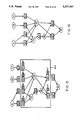
- FIG. 1 An overview of the method 10 for creating an executable model according to the present invention is shown in FIG. 1.
- a (preferably) graphical programming tool such as Design/CPN (available from Meta Software Corporation of Cambridge, Mass.) running on a suitable digital computer system (such as a SUN SPARC workstation from Sun Microsystems, Inc. of Mountain View, Calif.
- a model of the subject system is created.
- Step 12. For input devices, a keyboard 14, mouse 16 or similar devices may be emmployed.
- This model is built from a plurality of Colored Petri nets constituting submodels of parts of the system, the submodels being interrelated in a hierarchical fashion.
- Each of the individual submodel CPN's is assembled from places, transitions, arcs, arc inscriptions, and so forth, represented by suitable computer program code.
- the model, and the constituent submodels are represented to the modeller on a video display terminal, 18, or the like.
- the constructed model is actually a data base 20.
- a syntax check is performed. Step 22.
- the syntax check validates the structure of the model, to ensure that all necessary occurrence functions can be generated. If the syntax check fails, indicating the model violates a prescribed rule, the modeller edits the model using the tools and procedures of step 12, and again performs a syntax check. Once the syntax check passes, or succeeds, color set definitions are passed to another data structure 24.
- the executable code may be written in any of a number of programming languages, but we have found ML to be particularly useful. ML originated at the University of Edinburgh, Scotland. A commercial version of an ML compiler is available from Bell Telephone Laboratories or from Meta Software Corporation. When ML is employed, the data structure 24 may be the ML "environment.” Once the compiled code has been generated, it is executed, to simulate the system. Step 28.
- the graphical programming engine may be executed on the same processor as the compiled program code, or they may be executed on different processors.
- FIG. 2 a simple example is shown of a "flat" (i.e., non-hierarchical) Petri net model of a system.
- a simple system may, for example, be a subsystem of a more complex system. The nature of the system is unimportant; it might equally well be a system for manufacturing pharmaceuticals, a system for controlling elevators in a high-rise building or almost any other kind of system).
- Such a flat model is a dataflow representation of a computational process.
- it is a bipartite directed graph, with the vertex set partitioned into two sets. These sets are referred to as "transitions" and "places".
- the transitions label elements of action; the places denote local states which may be viewed as inputs and outputs of the transitions to which they are directly connected.
- the orientation of the arc connecting a transition and a place determines whether the selected place is an input place or an output place of the transition. (A given place may, for example, be an output place for a first transition and an input place for a second transition.)
- a place is analogous to a variable in programming languages, in that it contains structured values. It is different in that it can hold from zero to any number of values, each of which is separately accessible. New values are put in the place by the occurrence of transitions that have the place as an output. Values are removed (i.e., read) from a place by the occurrence of transitions that have the place as an input. Thus the values can be perceived as tokens that "flow" in the model. Indeed, in some Petri net hardware embodiments, tokens may be signal levels, states or the like which actually do propagate from one place to another.
- a place has two primary attributes, its "color set” and its "marking.”
- a color set is analogous to a "type” in programming languages and specifies the set of permitted contents for the place.
- a marking is analogous to a "value” in programming languages. It is a multi-set (i.e., a set whose elements are multiples) which specifies symbolically the set of tokens that reside on the place. Note that the marking has not been illustrated in the FIG. 2 example.
- the "state" of a flat model is a function mapping each place to its marking.
- place 38 has the name "in 1". This name plays no formal role in the model.
- a transition is analogous to a set of assignment statements in a conventional programming language, to a function in functional programming languages, and to a rule in a language like PROLOG. It can be viewed as a function which maps places' values to places' values.
- a transition has associated with it a number of attributes: input places, output places, variables, guards and code segments.
- the arcs from its input places to the transition are called the input-arcs of the transition.
- arc 62 is an input arc of transition 32.
- the inscriptions on those arcs e.g., the inscription "x" on arc 62
- the input-arc-expressions of the transition are called the input-arc-expressions of the transition.
- the arcs from the transition to its output places e.g., the arc 63
- the inscriptions on the output-arcs (e.g., the inscription "x*y" on arc 63) are called the output-arc-expressions of the transition.
- V(T) The set of all variables associated with a transition T is written as V(T), and is the set of variables which appear in its input and/or output arc-expressions.
- V(32) ⁇ x,y ⁇ , where the braces are used for conventional set notation.
- IV(T) The set of all input variables, IV(T) is the set of variables which appear on the input arcs; analogously for OV(T).
- V(T) is the union of IV(T) and OV(T).
- All variables a in V(T) such that a are not in IV(T) are known as "free variables".
- Some variables may appear only in output-arc-expressions; such a free variable can assume any value from its color set.
- the scope of all variables in V(T) is local to the transition T.
- a program fragment to be executed each time the transition T occurs is called a "code segment.”
- the variables in IV(T) may be used as inputs for a code segment.
- the variables in OV(T) may be assigned values as outputs.
- Reference variables mentioned in other code segments, but not otherwise in the model may be used as values or assigned new values.
- a binding for a transition T is a function which assigns to each of the transition's variables to a concrete value. Once a binding is determined, the arc-expressions of the transition are evaluated. This evaluation determines the tokens to be removed from the transition's input places upon the occurrence of the transition, and the tokens to he added to its output places.
- a transition is said to be “enabled” if there exists a binding such that the input places contain sufficient tokens to satisfy the binding.
- FIG. 3 is a portion of FIG. 2.
- the marking at each input place 52 (arg1), 54(arg2) is depicted by an inscription contained within the place.
- places arg1 and arg2 each contain a single token of type int (i.e., integer). This is a simplification of the general case; in general, the marking at each place is a multi-set which will be represented as a list of values.
- the goal of the binding process is to find one or all such bindings.
- the number of bindings can increase in direct proportion to the product of the number of tokens at each input place. (This is not the case if the same variable is used in more than one input-arc-expression or also occurs in the guard.) If more than one binding is legal, it still has to be determined whether more than one binding can be executed concurrently, i.e., in a single step. This will be discussed below.
- the process of finding a binding is a computationally intensive task as it involves traversing potentially large search trees and performing unification (i.e., finding multi-set unions) at each node.
- each transition T is characterized as a function which maps a labeled record of multi-sets having a component for each input place into a labeled record of multi-sets having a component for each surrounding place.
- the transition add can be represented by an occurrence function of the following type:
- the add function can be used to determine if the add transition can occur, and if so, to calculate the new markings of its adjacent places as a result of the occurrence. Assume that the markings of arg1, arg2 and result are a1m1, a2m1 and rm1 respectively. If the add transition cannot occur, the application of the add function will fail. However, if the transition can occur, then the application will succeed and the multiset of tokens a1d to be removed from arg1 will be calculated, the multiset of tokens a2d to be removed from arg2 will be calculated and the multiset of tokens rd to be added to result will be calculated. As a consequence of the occurrence of the add transition, the new markings of arg1, arg2 and result will be, respectively:
- such an occurrence function must encode all of the transition's arc-expressions and is, as a result, quite complex.
- a "layered approach" is taken herein in order to build such an occurrence function.
- For each transition there are defined: (1) a binding type; (2) for each input place associated with the transition, an input arc function; (3) for each output place, an output arc function; and (4) a function to calculate bindings for the transition.
- binding function for transition T is a function on V(T).
- bindings for the add transition are values of the following type:
- the arc-expressions of a transition are used to calculate the tokens to be removed from the associated input places upon occurrence of the transition and the tokens to be added to the associated output places. This calculation can be performed as a function application if each arc expression is cast as a function on the binding type of the transition. For example:
- the "fun” designation denotes a function.
- the backward apostrophe, ⁇ is an infix operator that constructs a multiset containing a given number of occurrences of a given color. As an example, n ⁇ x constructs n occurrences of color x.
- the syntax for input arc-expressions requires that an arc-expression evaluate to a multiset of the same type as is declared for the input place.
- the prefix ⁇ int>' ⁇ , and multi-set operations, such as multi-set addition, are explicitly allowed. Referring to FIG.
- the backward apostrophe operator in the expression 2 ⁇ x on arc 62 permits the removal of two identical tokens of color x from the input place 48 to be represented both graphically and textually as shown there.
- the tokens to be added to the output place are represented at 64 and 66.
- the multi-set addition operator 68 on arc 70 permits the removal of two tokens from place 48, one of color x (i.e., 74) and one of color y (i.e., 76), to be represented as shown in FIG. 5.
- input arc-expressions can be decomposed with explicit multi-set addition (or multiple identical tokens) by generating additional input arcs, such as arcs 82 and 84 as illustrated in FIG. 6.
- a reference to an input arc function is a reference to the unique (for each input place) function which evaluates to the appropriate multi-set.
- the occurrence function can be defined in terms of its associated arc functions.
- the occurrence function applies each of the arc functions to the "value" generated by the binding function to determine the multi-sets to be subtracted from each input place and added to each output place.
- Bindadd binding function for add
- Bindadd The process for determining the functionality of Bindadd is described in terms of search trees.
- the goal of the function Bindadd is to transform a completely unspecified binding b 0 into a completely specified binding b n such that
- #arg1 and #arg2 are selector functions which map the compound marking represented by the record for ipm into the arg1 and arg2 components.
- the process of generating a binding for a transition starts with all of the variables in V(T) unbound.
- the process of going from totally unbound variables to a full binding is a tree search which can be characterized recursively. At each node of the tree, all potential bindings must be explored until a success is reached (i.e., a partial binding is found, which appears to meet the requirements). Once a successful potential partial binding is found, the next "lower" level of the tree can be explored.
- step 100 determine whether there are any unbound variables. If not, skip to step 140; otherwise, proceed with step 102.
- step 102 determine whether there are any unprocessed input arcs (step 102); if not, skip to step 130 (point cc).
- step 104 select an unprocessed input arc.
- step 106 substitute for all bound variables occurring in the corresponding input arc-expression the values to which they are bound.
- step 108 perform any function applications that may now be carried out (i.e., executed).
- the selected arc-expression may now serve as a pattern to be matched against each of the tokens in the current marking of the selected input place associated with the input arc. There are three cases to consider:
- Case 1 A test is performed (step 110) to determine if any constants and/or already bound variables in the arc-expression are incompatible with the current marking, in which case pattern matching fails and the currently proposed partial binding cannot be completed. Thus a failure node has been reached in the search tree and a failure message is returned, as indicated at step 112. Control reverts to step 100, point DD, at which time the search moves one node higher on the tree and starts again.
- Case 3 The pattern match succeeds. Newly bound variables are then added to the proposed binding. (Step 118). Each such match corresponds to a branch of the search tree. Hence the number of "child" nodes in the tree is equal to the number of different matchable values in the marking. A recursive call of the process is made for each child, as indicated by decision step 120 and line 122. If a match is found for any child node, a success message is returned and control continues on line 124; otherwise, a failure message is returned on line 126 and control reverts to entry point.
- step 130 arc expressions marked by step 116 are checked to determine if any are now evaluable. If so, control branches to point DD and steps 100-128 are repeated until there are no more unbound variables or no more evaluable arc expressions.
- Step 132 determines which possibility applies, for each still-unbound variable.
- an unbound variable may be declared to be of a color set (i.e. type) with only a small number of values. In this case, branches can be generated for each such value, as if there had been a match (i.e., step 134).
- a color set may be large. In this case, a possible value can be generated by a random selection (possibly a number of attempts).
- the arc functions can now be evaluated (in step 140) to determine whether the input places contain the appropriate tokens. At this stage, multiple instances of the same token color, and multiple arcs from the same input place express themselves in the multi-sets resulting from the evaluation. Additionally, variable bindings made by random choice will be tested against what is actually possible. If the containment is satisfied, a success message is returned; otherwise, a failure message.
- This binding-generation process can traverse the tree in a depth-first or breadth-first manner in order to obtain a binding. (The depth-first approach works well for finding the first ⁇ n ⁇ bindings fast.) A variant of this function could also return a list of all possible bindings instead of just one binding. Other factors affect the efficiency of this whole process. Some of these factors are discussed below.
- the first thing to be determined is whether the add transition is enabled in state S 1 . Apply the occurrence function for add to the current markings on the input places of add. If the add transition is not enabled, the evaluation will fail and the enabling of other transitions should then be checked, until the enabling of all transitions has been checked. Assume that add is enabled. Then the function will calculate multi-sets using the input-arc functions and the output arc function. Let these be a1d, a2d and rd, respectively. Now, the state S 2 can be defined. This is the state arrived at as a result of an occurrence of the add transition in state S 1 :
- state S 2 would be:
- guard functions With transitions places a further constraint on the binding function.
- all variables in the guard must be included in V(T).
- the guard must evaluate to a true condition. (Recall that the guard is a Boolean list. Thus, each element of the list must evaluate to true).
- An easy way of incorporating the guard is simply to add it as a test on the proposed binding. In practice, it is more efficient to use the guard in the process of determining the binding because it reduces the fan-out in the search tree. This can be done as next described, for which reference is made to FIG. 8.
- the efficiency of the binding process can be greatly affected by the order in which arc expressions are used to bind variables.
- place 160 tends to have very few tokens on it, perhaps at most one at a time.
- place 162 arg2 of type tuple typically has many tokens, each with a unique value for x.
- the occurrence function is generated dynamically during the simulation of the model, the actual token count can be used to make the occurrence function more efficient.
- repeatedly redefining occurrence functions during the simulation is in itself very expensive.
- an occurrence function definition applicable to all possible bindings can be created. As such, it cannot depend upon a particular value to which a variable is bound. (In the description of the process of generating a binding, the partial binding is used in the pattern match of FIGS. 7A, 7B. Such values cannot be used in a precompiled pattern match.
- a set of subnets called pages can be related to each other in such a way that they together form a single system model.
- the system modeller can describe the complex system as a set of less complex submodels which all contribute to a much larger model in which the submodels interact with each other in a well-defined way.
- Each submodel can be separately designed, or described. This idea is well-known from other kinds of artificial languages, such as submodels in SADT and subroutines in programming languages.
- substitution node which is a place or a transition related to a submodel.
- the submodel totally replaces the substitute node and the surrounding arcs; hence, it does not make sense to say that a substitute transition occurs or that a substitute place is marked.
- the substitution node is not itself part of the final model.
- the user can switch between the two models (e.g., first investigate the simple one and then go on with the more complex one).
- the two models share most of the submodels; this means that changes in one of them automatically apply to the other.
- the first very substantial step on this path was to replace ordinary Petri Nets with high level Petri Nets such as Predicate/Transition nets and Colored Petri Nets.
- the second step is to introduce hierarchical models. In terms of programming languages, the first step can be compared to the introduction of types allowing the programmer to work with structured data elements instead of single bits. The second step may be compared loosely to the development of programming languages with subroutines allowing the programmer to work with reusable patterns. From a theoretical point of view, machine languages (or even Turing machines) are equivalent to the most powerful modern programming languages. From a practical point of view, this is, of course, not the case.
- Hierarchical modeling languages have been introduced to overcome these problems and have been in practical use for quite some time.
- SADT and IDEF Yourdon's data flow diagrams, and state charts.
- IDEF Yourdon's data flow diagrams, and state charts.
- executability implies that the modeling language supports the notion of behavior for its components in a precise and consistent way and makes it possible to observe the execution of large complex system models at different levels of detail. Most of the modeling languages in the group above do not possess these executability properties.
- Hierarchical constructs Each of these gives CPN's a more useful and more flexible expressive power.
- the aim of the hierarchy constructs is to guide the analyst to produce structured models by supplying a set of sound and consistent structuring concepts.
- the point of departure is the ordinary non-hierarchical CP-net.
- the transitions can be seen as schemes for behavior, in the sense that the actual binding determines the details of the behavior.
- the number of tokens moved along an arc may depend upon the actual binding and it may even, for some bindings, be zero.
- a set of transitions and bindings occurring concurrently is called a "step” (though that word may be used in a more colloquial sense, as well).
- a diagram is a set of related non-hierarchical CPN's called "pages".
- the semantics of the new hierarchy constructs are defined by showing how each use of them can be translated into an equivalent non-hierarchical CP-net which has exactly the same reachable system states and enabled steps.
- This approach of introducing new language constructs by specifying a translation to well-known old constructs is traditional. Exactly the same thing was done when CP-nets (and Predicate/Transition Nets) were defined by means of ordinary Petri Nets (PT nets). It should be stressed that the only purpose of this translation is to define and present the hierarchy constructs without constructing an intermediate flat CP-net. This extension of CP-nets implies that the existing analysis methods must be extended to cope directly with hierarchical CP-nets.
- the hardware plug-in e.g., a silicon chip.
- a component with a set of interface posts or terminals.
- Such a component can be connected to a given environment (e.g., circuit) by means of socket connectors which are attached to the posts.
- socket connectors which are attached to the posts.
- the only thing to be done is to specify the correspondence between sockets and posts. Going back to the CP-nets, a transition may be considered as such a component and its surrounding places as the interface to the environment.
- FIG. 10 An example will help to clarify the idea.
- a simple assembly line 170 in a factory consisting of three machines 172, 174 and 176, and two intermediate buffers 178 and 180.
- the machines are identical and need be model led only once. The same is true for the buffers.
- the page 182 in the left part of FIG. 10 represents each machine, Mach1 and Mach3, and each buffer, Buf1 and Buf2, as a substitute or substitution transition.
- the details of the machines and buffers are described on two other pages 184 and 186 in the right part of FIG. 10.
- This inscription tells the name and the number of the subpage and it describes how each of the places surrounding the compound transition is assigned to one of the border nodes of the subpage.
- Most of the other net inscriptions have been omitted to focus more on the net structure than the details of color sets, arc expressions, and so forth.
- Each substitution transition designates a page. This page is said to be a subpage. Such a substitution transition represents the component as a black box, whereas the subpage contains the details of how this component actually performs the activity.
- the substitution transition is a shorthand for the CP-net on the subpage.
- FIG. 11 illustrates the idea of this node-to-page relationship for an abstract net.
- the substitution transition 210 and its page 212 are, with respect to the subpage 214, said to be a supernode and a superpage. For simplicity, most of the CP-net inscriptions are again omitted.
- the substitution transition, SubTrans 210 can be recognized by the HS-tag 216.
- SubTrans 210 has five surrounding places PA, PB, PC, PD and PE which are called socket places; three of these (PA, PB and PC) are input socket places and two are output socket places.
- Five places on the subpage, (PA, PC, PD, PF and PG) are defined to be port places and, hence, are marked by B-tags (e.g., B-tag 218).
- the port places represent the posts from the hardware metaphor. They are the interface to the upper level at which the subpage is plugged in and used.
- the relationship between socket places and port places is called the port assignment. It is a function mapping sockets into ports. The port assignment is shown in the inscription PB ⁇ PF, PE ⁇ PG next to the HS-tag of the substitution transition.
- the first line of the inscription tells the name and number of the subpage.
- Each of the remaining lines describes the assignment between a socket and a port.
- the only sockets mentioned are those which are unassigned or assigned to a port with a different name.
- the lines PA ⁇ PA, PC ⁇ PC and PD ⁇ PD have been omitted. It is required that all socket nodes be assigned and that a socket node be assigned to a port node with an identical color set.
- the port assignment function is, however, allowed to be non-injective and non-surjective.
- the inscriptions next to the B-tags of port nodes (e.g., inscription 220) tell whether the assigned socket node has to be an input, output or input/output node for the substitution transition.
- the modeller can also define a port node to be general, and this means that all three kinds of socket nodes can be assigned.
- System components are reusable. Once a given building block has been designed and verified, it may be used at several locations. Hence, an important feature of this framework is that the same page may be used as a subpage for several substitution transitions even on different pages.
- the assembly line example uses both Machine#2 and Buffer#3 as multiple use plug-ins.
- FIGS. 12 and 13 show how to translate it into an equivalent non-hierarchical CP-net. This is done in two steps. First, the substitution transition 210 (together with its surrounding arcs) is deleted and a copy of the corresponding subpage 214 is inserted, as FIG. 12 illustrates. Second, each socket place is merged with the assigned port node. FIG. 13 shows the merger. In general, the result of a merge of two nodes A and B is a node C with a set of arcs which is the union of the arcs of A and B.
- Each subpage is a template. From that template, copies can be made to replace the corresponding substitution transitions. Such copies are referred to as (substitution) instances of the actual page.
- the initial marking of the subpage is copied together with the net structure. Each port place, however, inherits (and shares) the initial marking of the assigned socket (if any).
- the page instances form the instance hierarchy and one can speak about "superinstances" and "subinstances” in a similar way one refers to superpages and subpages.
- FIG. 14 shows a substitution place SubPlace 220 together with its subpage 222, Queue#4.
- SuperPage #13 the substitution place 220 outlines a simple data type, a queue with three operation handles: Init, Put, and Get. In this case, Init is called once, Put three times and Get twice. These calls are represented by the six socket transitions 231-236 surrounding SubPlace. As for substitution transitions, some port nodes are allowed to be unassigned. Moreover, as illustrated above, several socket transitions (e.g., 231 and 232) are often assigned to the same port (e.g., 238). At the subpage, the three operations are described in more detail and the interface to them is represented by the three port transitions.
- substitution places is similar to the semantics of substitution transitions. The roles of places and transitions are, however, reversed and, in addition to this, there are a number of minor differences.
- the definition of the semantics of a substitution place involves two steps, illustrated in FIGS. 15 and 16 for the net in FIG. 14. First, the substitution place (together with its surrounding arcs) is deleted, a copy of the subpage 222 is created and each port transition is duplicated to obtain a copy of each of the assigned socket transitions. This is shown in FIG. 15.
- the result of a duplication of a node A is a new node B which has exactly the same set of arcs as A. When a port has only one assigned socket node, no duplication is needed. Unassigned ports are deleted.
- each socket transition is merged with a copy of the port transition to which it is assigned (See FIG. 16); the guard in the resulting transition is the conjunction of the guards for the socket node and the port node.
- the merge implies that a socket transition has to occur together with its corresponding port transition as a single indivisible state change.
- transitions Request 204 and Remove 207 are defined to be port transitions by placing a B-tag next to them (i.e., associating a B-tag with each of them).
- Assembly Line#1, 182 is then used (at 182A, 182B) as a subpage for each of two substitution places Assembly1 and Assembly2 (240, 242, respectively), as shown in FIG. 17.
- Queue#4 (222) from FIG. 14 is used as a subpage 222A for a front-end queue 244 named InQueue and as a subpage 222B for a back-end queue 246 named OutQueue.
- This small example illustrates how easy it is to extend the scope of a model by inserting it as a submodel in a larger model.
- a substitution place SP is not allowed to be neighbor to a substitution transition ST. The reason is that it then would be impossible to construct an equivalent non-hierarchical CP-net by the method defined above, because SP is socket for ST and vice versa. It is possible to extend the foregoing concepts to cover such a case, though.
- a subroutine is declared with a set of formal parameters and it can be invoked (i.e., called) from different locations by supplying a set of actual parameters. Each call implies a temporary instantiation of the subroutine.
- a subpage 250 (PresCalc#6) is defined, as shown in FIG. 18. It is invoked by three different invocation transitions: PresCalc 252 (at Machine #2), PC1 254 and PC2 256 (at PresCalc#6). In contrast to substitution nodes, the invocation transitions are not substituted by their subpage. This means that they can occur, and that each of their occurrences triggers the creation of a new instance of the subpage. These subpage instances are executed concurrently with the other page instances in the model until some specified exit condition is reached. When an invocation page instance is created or terminated, tokens are passed between the invocation transition and the subpage instance, similar to the way in which parameters are passed between a subroutine call and the subroutine execution.
- Each invocation of PresCalc#6 receives a token from the input node of the calling invocation transition and then classifies the task as either simple 262 or complex 264.
- the result is immediately calculated and passed back to the invocation transition via Stop 266 and the execution of the subpage is destroyed because an exit place received a token.
- the task is divided by transition 268 into two recursive subtasks (represented by PC1 and PC2). The results of the two subtasks are tested by transition 270 against a database 270 and, finally, a token is put either on Stop place 266 (if the test was positive) or on place Q (if the test was negative).
- the invocation subpage represents the subroutine description while the invocation transition represents the subroutine call. All the ports must be places and they represent the formal parameters. The places surrounding the invocation transition are called parameter places and they represent the actual parameters.
- the termination of subroutine execution is usually triggered by execution of the last statement or by an explicit exit statement. In the present framework, it is not always possible to talk about the last node; the analyst is only permitted to define exit nodes. The execution is terminated the first time and exit transition occurs or an exit place receives a token.
- the enabling rule for invocation transitions is identical to that of ordinary transitions, but an occurrence of the invocation transition (e.g., invocation transition 280) implies a temporary extension of the CP-net, as illustrated in FIG. 19:
- a new instance 214A of the invocation subpage is created.
- This subpage may contain substitution nodes and, when this is the case, it is necessary also to create new page instances of the corresponding substitution subpages.
- These page instances become subinstances of the invocation page instance and they may themselves have subinstances (if they contain substitution nodes).
- the arc expressions on the input arcs of the invocation transition are evaluated and the corresponding tokens are subtracted from the input parameter places and added to the assigned port places (in the invocation instance).
- substitution nodes For substitution nodes, one can statically calculate the equivalent non-hierarchical CP-net. For invocation transitions, this is not possible and it is necessary dynamically to extend and shrink the equivalent non-hierarchical CP-net. Without invocation, each page has a constant number of instances; but with invocation, the number of page instances may change (even for pages which only are substitution subpages). Moreover, each invocation transition can have any page as a subpage (as long as the ports are places). This means that the invocation hierarchy is allowed to contain circular (i.e., recursive) dependencies while the substitution hierarchy is restricted to being acyclic (to avoid infinite substitution).
- steps (a) and (c) above is analogous to the use of in, out, and in+out parameters in subroutines. This is also sometimes known as call-by-value and call-by-result.
- Some programming languages, e.g. Pascal allow subroutines to be passed as parameters to other subroutines. Analogously, token colors might be allowed to represent CP-nets.
- fusion is obtained by defining a fusion set containing an arbitrary number of places or an arbitrary number of transitions.
- the nodes of a fusion set are called fusion set members.
- FIG. 20A where the CP-net 284 has a fusion set called FusA.
- FusA is a page fusion set; this means that it is only allowed to have fusion set members from a single page in the diagram.
- FIGS. 21A and 21B where it is assumed that the page has two page instances 292 and 294. Both possibilities are useful; thus, the user is allowed to specify which of them he wants.
- FIG. 21A is obtained by making fusion set FusA a page fusion set
- FIG. 21B is obtained by making it an instance fusion set (with FI-tags).
- the members of a fusion set must be comparable to each other. For places, this means that they must have the same color set and the same initial marking. It also means that they either must all be ordinary places or all be substitution places; and, in the latter case, they must all have the same subpage. Fusion of substitution places is useful when one wants to apply the same instance, e.g., an abstract data type, at several locations in the diagram.
- the cache coherence protocol modeled in the Huber paper illustrates the use of this facility.
- transition fusion Exactly the same set of concepts applies to transition fusion.
- the guards are not necessarily identical. Instead, the conjunction of the guards is formed.
- the members of a transition fusion set must all be (a) ordinary transitions, (b) substitution transitions, or (c) invocation transitions. In the latter two cases, they must all have the same subpage.
- fusion is mainly a drawing convenience. However, when applied to nodes at different pages, or to pages which have several instances, fusion becomes a strong description primitive in its own right, and it supplements the notions of substitution and invocation in a very fruitful way.
- FIG. 18 the use of all three kinds of fusion sets is illustrated. Resources shared by all machines are modeled by a page fusion set ComRes 300, while resources local to one machine are modeled by an instance fusion set LocRes, 302. Finally, the Data Base is modeled by a global fusion set DB 273, since another page (not shown) has the responsibility of updating the database. When modeling the data base as an abstract data type, the corresponding places become both substitution and fusion places.
- a graph called a page hierarchy is used.
- An exemplary page hierarchy appears in FIG. 22, representing the small factory unit of FIG. 10.
- Each node represents a page and the shape of each such page node tells what kinds of supernodes the page can have.
- An ellipse shape (e.g., node 310) indicates that all supernodes must be places; a box shape (e.g., node 312) that they must be transitions; and a rounded box shape (e.g., node 314) that there is no restriction.
- Each arc represents a hierarchical relationship between two pages and the graphics tell whether the arc represents a substitution relationship, an invocation relationship, or a global fusion set.
- a substitution relationship may be shown by a heavy line, as at 314; an invocation relationship, by a light line, as at 316; and a global fusion set by a textured line, as at 318.
- Page and instance fusion sets are not represented in the page hierarchy because they involve only a single page.
- the page hierarchy graph can be generated automatically. The user can, however, change the layout and graphics in any way he might want.
- the page hierarchy is an integrated part of the user interface. As an example, the user may delete a page by deleting the corresponding page node in the page hierarchy.
- Prime pages To specify the initial state for an execution of a hierarchical CP-net, the user must define a set of starting pages called prime pages. Declaring FactoryUnit#5 to be a prime page means that the execution will start with one instance of FactoryUnit#5, two instances of Queue#4, two instances of AssemblyLine#1, six instances of Machine#2, and four instances of Buffer#3. Instead, AssemblyLine#1 could have been declared to be a prime page and then only a single assembly line would have been indicated, containing one instance of AssemblyLine#1, three instances of Machine#2, and two instances of Buffer#3. In general, the user is allowed to have more than one prime page and he can even let the same page be a multiple prime. Intuitively, the prime pages tell what should be included in the execution.
- Buffer#3 is excluded, no instances will be created for this page and Buf1 and Buf2 will be treated as if they were ordinary places. It is important to be able to include and exclude parts of a model without having to change the model itself.
- the arc expressions of the substitution transition BreakSen, 332, at Phone#1 give a slightly less detailed description of the corresponding activity than the subpage BreakSen#4, 321.
- the substitution transition does not show that the activity has two subactivities (which are executed after each other) and it does not show that Engaged is updated.
- BreakSen still gives the reader a very good idea about what the activity does. It describes the combined effect of the two subactivities on the markings of the socket places.
- the arc expressions of the substitution transition EstabCon at Phone #1 are used in another way. They describe what happens in the normal case where a connection is established. However, they do no say that the result of the subpage activities may be that no connection is established (routing both the x and y token to Inactive instead of Connected). It would not have been particularly difficult to describe this possibility in the arc expressions, but the analyst has, at Phone#1, chosen to concentrate on the normal case.
- the electronic bank-to-bank funds transfer is the large electronic payment process that effects the movement of funds between banks primarily through the use of payment networks.
- the average daily value of the funds transfer is on the order of hundreds of billions of dollars.
- the recognition of the risk for tremendous losses in case something goes wrong has imposed on the funds transfer a set of limitations on debt utilization, slowing down the rate of flow of money. Still things may go wrong.
- a new method of processing bank-to-bank transactions has been needed. This method must incorporate all the limits and self-regulations that the market and the relevant government institutions have imposed. At the same time, it must make better use of capital resources of banks and produce a lower average debt, reducing the inherent risks. Then it will be used to process the day's business in advance in two ways: first by predicting the debt positions as the day evolves and second by determining in what sequence the payments should be executed. This new method is decomposed into three major activities: Source Data Management, Debt Simulation Modelling and Debt Management.
- the Source Data Management activity all necessary data is collected and pre-processed.
- the payments are collected from the originating business areas and split into two subsets: (1) the "actuals" set, composed of transactions that have already been executed through the networks and that update the current debt position; and (2) the futures set, composed of transactions that still have to be processed.
- the customer balance which limits the amount of funds that may be withdrawn from a customer of the bank
- the bilateral balance which limits the debt that each bank will accept from another bilateral agreements
- the network balance which limits the overall debt any institution may have within the CHIPS (Clearing House Interbank Payment System, built and supported by approximately 140 banks and used primarily for international dollar payments) and the FEDWIRE (built and supported by the U.S. Federal Reserve Bank and used primarily for U.S. domestic payments) networks, alone or cross-checked.
- CHIPS Clear House Interbank Payment System
- FEDWIRE built and supported by the U.S. Federal Reserve Bank and used primarily for U.S. domestic payments
- the futures set can be evaluated to determine (a) the transactions for which the expiration date is close, in which case they will be processed immediately, and (b) the set of transactions that have not reached their expiration dates. Since the number of payments that can be executed every hour is limited by the network characteristics, the rate of flow of money can be increased by grouping together transactions with similar characteristics, such as the debit and credit parties. Also the net result of incoming and outgoing payments with similar characteristics may be calculated, reducing the amount of money that travels through the networks.
- the payments that exceed the limits are processed. These payments generate exceptions that can be overridden on the basis, for example, of an expected receivable. If an exception is overridden, then it is re inserted into the list of payments that are being processed. If the exception is not overridden then the payment that generated it will not be executed at that time.
- a "debt" plan is produced.
- This debt plan can be reviewed and proposed as the script for executing transfers.
- some of the parameters that control the method may be changed, such as the sequencing scheme, so that a different debt plan will be produced.
- MID-SADT Manage Intraday Debt SADT model
- MID-CPN CPN model
- SADT Structured Analysis and Design Technique
- the SADT methodology is not usually considered adequate for direct representation of executable models (i.e., programs).
- the arrow structure it uses is intentionally ambiguous in respect to the representation of such concepts as concurrency and choice, these being regarded as implementation details to be left unspecified until needed.
- the activation rules by which the detailed behavior of undecomposed activities is specified are too primitive and a formal theory of behavior based on these rules has not been elaborated.
- the model is executable. Therefore the CPN methodology, unlike SADT, is not used only to build system specifications but also to validate a system's design through simulation and other more formal kinds of analysis.
- CPN is a programming methodology and system with which executable models can be built.
- CP-nets are not usually considered adequate for directly executing the production version of the system under development. This happens because the high-level interactive graphical programming environment limits the efficiency of the execution.
- Standard ML is a functional programming language in which the total behavior of a system is encoded into a textual representation and no use is made of any kind of graphical object. It is used to build production versions of CP-net models.
- SADT models can be converted into equivalent CPN models, with similar graphical lay-out, where detailed behavioral modelling is possible. Moreover, problems related to concurrency and choice, non-specified in the SADT model, can be addressed properly with CPN inscriptions. These inscriptions can also be added directly to the SADT model, so that it is possible to convert it and execute the resulting CPN model. The conversion process can be hidden from the end-user, so that the SADT model becomes executable, where the behavior is still defined by the underlying CPN model.
- CPN models can, in their turn, be converted into "pure” SML applications.
- the basic idea here is to eliminate the entire CPN graphical representation without eliminating its computational semantic.
- the net structure that regulates the CPN execution can be completely hidden from the end-user so that a different interface system can be built.
- an SADT model called the "MID-SADT” model, portraying the new method of managing intraday debt, was built.
- the SADT methodology was chosen, at this stage, because of its very simple semantics and its "loose” syntax; both were believed to be easy to learn by the bank managers responsible for the creation of the model.
- the structure of the CPN model called the MID-SADT model was improved, it was automatically converted into a CPN model.
- the generation of a CPN model called the "MID-CPN" model was commenced through an automatic conversion of the MID-SADT model.
- the basic data structures of the model were defined in terms of color sets and the basic operations to be performed on this data were specified in terms of arc inscriptions, guards and code segments. Since the purpose of this initial phase was to validate the logic of the net structure of the model, not too much effort was put into the process of specifying all the details of both the color sets and the net inscriptions. Nevertheless, all of the most important functions of the model were written at the level of detail considered to be relevant. This model was then validated.
- an SML application was built as a prototype of the final production version of the system. This prototype was first produced in a manual fashion. Then a simple algorithm for generating the SML application automatically from the MID-CPN model was implemented.
- the net structure of the MID CPN model is hierarchical, with three levels of decomposition. There are a total of 8 pages, plus a separate page containing the color set declarations and the SML functions. On these pages there are twenty-four non-decomposed transitions (i.e., transitions that do not have a subpages that replaces them).
- a diagram (called a Hierarchy Page) showing the hierarchical relationships between the pages of the model is presented in FIG. 32, which is discussed below.
- the input data for the model can be described as a list of bank-to-bank transactions. Transactions are characterized by the identification number, the originating business area, the method of payment, the day and hour at which they are due (i.e. the deadline), the amount, the debit and credit parties.
- the set of bank-to-bank transactions is defined as a list of individual payments:
- the originating business areas are defined as elements of an enumerative set:
- the transactions method i.e. which network the payment is going to be sent through
- the type credit or debit
- color Agreements record PartiD:String*DealTypE:DealType* ChipAgR:Bank -- AgrList* FedAgR:Bank -- AgrList;
- Payments that do not pass limits are represented as a product set between an enumerative set that establishes which of the limits were not passed and the list of payments:
- Variables of a given color set to be used in arc expressions, guards and code segments, are defined in a programming language fashion, as in the following example:
- the color set declarations, the variable declaration and the user defined SML functions that are used in the inscriptions of the CP-net, are placed in special objects, called declaration nodes.
- This transition performs a very simple load input operation, reading from an external file and converting it into a list of transactions.
- the presence of the initial marking (), 402, of color unit, 404, on the input place 406 enables this transition 400 to occur as soon as the simulation begins.
- the variable u of type unit is bound to the value (), (in order to the match the initial marking) thus removing the token from the input place.
- the values for the tokens on the output arcs are calculated by the execution of the code segment 408.
- the output clause of the code segment determines which variables calculated within the code segment will be bound to the corresponding variables on the surrounding output arcs.
- the action clause of the code segment determines how the output values are calculated.
- two lines of SML code perform the desired effect: first a reference variable infile of type instream (i.e., a pointer to an input file) is associated with a specific file in the system file (FUTURES). The complete pathname of the file is specified within the variable CUR -- DIR. The second line of code applies two functions to this reference variable, thus generating a value for interlist.
- transition 410 performs a split of two lists of incoming transactions, interlist and intralist, into two lists: one representing the transactions that have not yet been executed (the futures) and one representing those that have already been executed (the actuals).
- tokens must be sitting on the two input places 412 and 414.
- this transition will be enabled.
- the variables on the input-arc-expressions intralist, interlist
- the values for the tokens that will be put on the output places 416 and 418 are calculated by the output-arc-expressions.
- each function is defined in two separate clauses (the symmetry of the functions can be noticed).
- the second clause looks at the type of the transaction and decides whether it should insert it in its recursive call. In this way, the Future function will produce a list containing only futures and the Actual function will produce a list containing only actuals.
- the values for the tokens that will be put on the output places are now calculated by the execution of the code segment 420.
- the input clause determines which variables on the surrounding input arcs will be used in the code segment.
- the input clause 422 determines which variables on the surrounding input arcs will be used in the code segment.
- the output clause 424 determines which variables calculated within the code segment will be bound to the corresponding variables on the surrounding output arcs.
- the action clause 426 of the code segment determines how the output values are calculated. In this particular case, the values for the variables on the output clause are calculated by the following SML function:
- This function now returns two lists and is defined in terms of a function that inserts the transactions in its second argument if the payment is a future, or in its third argument if the payment is an actual.
- the first clause of the local function returns the complete lists of actuals and futures, when the input becomes empty.
- the syntax check verifies that for the overall model, there is exactly one global definition node and at most one temporary local definition node.
- ports assignments are checked for connecting submodels, to ensure that ports and sockets match up.
- the initial marking is verified to be of the proper type, as specified by the color set.
- SML functions play a major role in the development of the MID-CPN model since most of the detailed behavior associated with the occurrence of the transition is specified as SML code.
- this code and its individual testing can be done independently of the CPN model execution, using an SML interpreter as a code evaluator.
- SML interpreter as a code evaluator.
- syntax checking the functionality of the code is checked so that it evaluates to the color sets of the places connected to the arcs where the function will be used.
- the function can be redefined so that it performs a complex ordering scheme based on type of transaction and amount. Then by adding one arc 437 and one place 438 many different sequencing schemes can be implemented, as shown in FIG. 31.
- the model was tested in automatic mode. In this simulation mode, random choices are made of which enabled transitions should occur.
- the focus of the simulation was then to find out whether the logic of the model satisfied the modeller's expectations, in terms of resource sharing, synchronization, etc.
- the main interest was therefore to observe the token flow within the model.
- As input data for the simulation a few transactions (maximum 50-100) were used and in some case none (i.e., empty lists), since the occurrence sequence of this model does not change by using a large or small number of transactions as input data.
- the speed of the transaction processing in the simulator was too slow to make it useful in real time.
- the number of transactions that are processed every day in the real world is between 10,000 and 30,000 depending on the particular institution, and for an application to be of practical use it must process them at least once in less then 15 minutes.
- This SML program was based on a fixed transition occurrence sequence recorded during simulation. Since all events in the MID-CPN model occurred in this sequence, it is possible to strip out all the enabling calculation and occurrence set calculations by writing appropriate SML code.
- transition 400 that loads the Interday Posts is written using SML syntax in the following way:
- val interlist (GetList GetTrans) (infile);
- CPN model such as the MID-CPN model
- MID-CPN model can be built automatically from the Meta Software Corporation (Cambridge, Mass.) Design/CPN tool in a few minutes. This is particularly useful in those cases in which it would be very complicated to manually produce the code, as when the CPN model has several hundred transitions. This is made possible by the existence of a number of SML functions that are built for every transition in a given model. These functions remove tokens, execute code actions, generate new tokens and update the current markings.
- This SML application can be executed both as an independent application or still within the CPN graphical interface.
- the process generating such an application can be viewed as a CPN compilation facility in which models and sub-models can be compiled into executable code.
- an occurrence sequence In order to compile a model, an occurrence sequence must be chosen by the user or by the simulator/compiler. These occurrence sequence determines the order in which the compiled model will attempt to execute its transitions.
- the generated SML code will try to execute every transition in the compiled net once in every step according to some order. If the user specifies the occurrence sequence, the generated SML code will try to execute every transition in the compiled net once in every step according to the order specified by the user.
Abstract
Description
a1m1-a1d, a2m1-a2d, and rm1+rd.
type add'BT={x:int,y:int}
fun arg1.sub.-- add.sub.-- AF ({x,y}:add'BT) : int ms=x (*=1`x *)
fun arg2.sub.-- add.sub.-- AF ({x,y}:add'BT) : int ms=y (*=1`y *)
fun add.sub.-- result.sub.-- AF ({x,y}:add'BT) : int ms=(x+y) (*=1`(x+y) *)
Bindadd : {arg1 : int ms, arg2 : int ms}→add'BT
arg1.sub.-- add.sub.-- AF(b.sub.n)←#arg1(ipm) and
arg2.sub.-- add.sub.-- AF(b.sub.n)←#arg2(ipm)
S.sub.2 (arg1)=S.sub.1 (arg1)-a1d,
S.sub.2 (arg2)=S.sub.1 (arg2)-a2d,
S.sub.2 (result)=S.sub.1 (result)+rd;
S.sub.1 '(arg1)=S.sub.1 (arg1)-a1d,
S.sub.2 '(arg2)=S.sub.1 (arg2)-a2d,
S.sub.2 '(result)=S.sub.1 (result)+rd;
S.sub.2 (arg1)=S.sub.1 (arg1)-(a1d+a1d'),
S.sub.2 (arg2)=S.sub.1 (arg2)-(a2d+a2d'), and
S.sub.2 (result)=S.sub.1 (result)+(rd+rd')
Claims (2)
Priority Applications (3)
| Application Number | Priority Date | Filing Date | Title |
|---|---|---|---|
| US07/507,119 US5257363A (en) | 1990-04-09 | 1990-04-09 | Computer-aided generation of programs modelling complex systems using colored petri nets |
| PCT/US1991/002418 WO1991015828A1 (en) | 1990-04-09 | 1991-04-09 | Method and apparatus for creating and executing graphical models of complex systems |
| AU76885/91A AU7688591A (en) | 1990-04-09 | 1991-04-09 | Method and apparatus for creating and executing graphical models of complex systems |
Applications Claiming Priority (1)
| Application Number | Priority Date | Filing Date | Title |
|---|---|---|---|
| US07/507,119 US5257363A (en) | 1990-04-09 | 1990-04-09 | Computer-aided generation of programs modelling complex systems using colored petri nets |
Publications (1)
| Publication Number | Publication Date |
|---|---|
| US5257363A true US5257363A (en) | 1993-10-26 |
Family
ID=24017332
Family Applications (1)
| Application Number | Title | Priority Date | Filing Date |
|---|---|---|---|
| US07/507,119 Expired - Fee Related US5257363A (en) | 1990-04-09 | 1990-04-09 | Computer-aided generation of programs modelling complex systems using colored petri nets |
Country Status (3)
| Country | Link |
|---|---|
| US (1) | US5257363A (en) |
| AU (1) | AU7688591A (en) |
| WO (1) | WO1991015828A1 (en) |
Cited By (60)
| Publication number | Priority date | Publication date | Assignee | Title |
|---|---|---|---|---|
| US5325533A (en) * | 1993-06-28 | 1994-06-28 | Taligent, Inc. | Engineering system for modeling computer programs |
| US5555179A (en) * | 1993-09-03 | 1996-09-10 | Hitachi, Ltd. | Control method and control apparatus of factory automation system |
| US5576965A (en) * | 1992-04-16 | 1996-11-19 | Hitachi, Ltd. | Method and apparatus for aiding of designing process |
| US5581688A (en) * | 1993-04-29 | 1996-12-03 | Telefonaktiebolaget Lm Ericsson | Tele- and data communication system |
| US5610828A (en) * | 1986-04-14 | 1997-03-11 | National Instruments Corporation | Graphical system for modelling a process and associated method |
| US5625559A (en) * | 1993-04-02 | 1997-04-29 | Shinko Electric Co., Ltd. | Transport management control apparatus and method for unmanned vehicle system |
| US5640567A (en) * | 1994-05-19 | 1997-06-17 | Sun Microsystems, Inc. | Apparatus and method for software system management using second-order logic |
| US5680530A (en) * | 1994-09-19 | 1997-10-21 | Lucent Technologies Inc. | Graphical environment for interactively specifying a target system |
| US5692233A (en) * | 1992-05-28 | 1997-11-25 | Financial Engineering Associates, Inc. | Integrated system and method for analyzing derivative securities |
| WO1998029817A1 (en) * | 1996-12-25 | 1998-07-09 | Emultek Ltd. | Device for implementing hierarchical state charts and methods and apparatus useful therefor |
| US5799157A (en) * | 1994-12-13 | 1998-08-25 | Elcom Systems, Inc. | System and method for creating interactive electronic systems to present information and execute transactions |
| US5872958A (en) * | 1997-05-01 | 1999-02-16 | International Business Machines Corporation | Method for flexible simulation modeling of multi-component systems |
| US5878407A (en) * | 1995-04-18 | 1999-03-02 | International Business Machines Corporation | Storage of a graph |
| US5893913A (en) * | 1996-11-12 | 1999-04-13 | International Business Machines Corporation | Method for synchronizing classes, objects, attributes and object properties across an object-oriented system |
| US5907706A (en) * | 1996-11-12 | 1999-05-25 | International Business Machines Corporation | Interactive modeling agent for an object-oriented system |
| US5917498A (en) * | 1996-11-12 | 1999-06-29 | International Business Machines Corporation | Multi-object views in an object modeling tool |
| US5930512A (en) * | 1996-10-18 | 1999-07-27 | International Business Machines Corporation | Method and apparatus for building and running workflow process models using a hypertext markup language |
| US5960199A (en) * | 1996-11-12 | 1999-09-28 | International Business Machines Corporation | Model trace view for object-oriented systems |
| US5983016A (en) * | 1996-11-12 | 1999-11-09 | International Business Machines Corporation | Execution engine in an object modeling tool |
| US5991536A (en) * | 1996-11-12 | 1999-11-23 | International Business Machines Corporation | Object-oriented tool for registering objects for observation and causing notifications to be made in the event changes are made to an object which is being observed |
| US6002850A (en) * | 1992-07-15 | 1999-12-14 | New Media Development Association | Operation sequence user adaptive system and method |
| US6011559A (en) * | 1996-11-12 | 2000-01-04 | International Business Machines Corporation | Layout method for arc-dominated labelled graphs |
| US6041263A (en) * | 1996-10-01 | 2000-03-21 | Aspen Technology, Inc. | Method and apparatus for simulating and optimizing a plant model |
| EP1066581A2 (en) * | 1998-03-04 | 2001-01-10 | Genesys Telecommunications Laboratories, Inc. | Telephony call-center scripting by petri net principles and techniques |
| US6185469B1 (en) * | 1997-05-28 | 2001-02-06 | Board Of Regents, The University Of Texas System | Method and apparatus for testing and controlling a flexible manufacturing system |
| US6230066B1 (en) * | 1998-09-08 | 2001-05-08 | Ford Global Technologies, Inc. | Simultaneous manufacturing and product engineering integrated with knowledge networking |
| US6243763B1 (en) | 1996-11-12 | 2001-06-05 | International Business Machines Corporation | Method for sending a message to a group and the group broadcasts the message to its members or references within an object-oriented system |
| US6256598B1 (en) | 1998-07-10 | 2001-07-03 | The Regents Of The University Of Michigan | Method and system for creating a control-flow structure which represents control logic, reconfigurable logic controller having the control logic, method for designing the controller and method for changing its control logic |
| US20010051971A1 (en) * | 2000-03-16 | 2001-12-13 | Toshiaki Kato | Parallel object task engine and processing method |
| US20030055811A1 (en) * | 2001-09-20 | 2003-03-20 | Ricoh Company, Ltd. | Document controlled workflow systems and methods |
| US6557157B1 (en) * | 1997-04-10 | 2003-04-29 | Boethel Andreas Frank | Method for designing complex digital and integrated circuits as well as a circuit structure |
| US6587746B1 (en) * | 1996-12-04 | 2003-07-01 | D'souza Melanius | Process and apparatus for facilitating automatic production of drawing using a CAD system |
| US6601023B1 (en) * | 1998-10-16 | 2003-07-29 | Computer Associates Think, Inc. | Method for impact analysis of a model |
| US20030233365A1 (en) * | 2002-04-12 | 2003-12-18 | Metainformatics | System and method for semantics driven data processing |
| US6671874B1 (en) * | 2000-04-03 | 2003-12-30 | Sofia Passova | Universal verification and validation system and method of computer-aided software quality assurance and testing |
| US6694505B1 (en) | 1999-11-25 | 2004-02-17 | Kim Seng Holdings Pte. Ltd. | Method for using a data flow net to specify and assemble computer software |
| US20040044608A1 (en) * | 2002-06-12 | 2004-03-04 | Young Nicholas A. | Systems and methods to facilitate generation of pricing information via a pricing graph |
| US6754879B1 (en) * | 1997-01-27 | 2004-06-22 | Unisys Corporation | Method and apparatus for providing modularity to a behavioral description of a circuit design |
| US6898782B1 (en) | 1997-10-14 | 2005-05-24 | International Business Machines Corporation | Reference-based associations using reference attributes in an object modeling system |
| US20050160401A1 (en) * | 1999-10-16 | 2005-07-21 | Computer Associates Think, Inc. | System and method for adding user-defined objects to a modeling tool |
| US20050166080A1 (en) * | 2004-01-08 | 2005-07-28 | Georgia Tech Corporation | Systems and methods for reliability and performability assessment |
| US6944851B1 (en) * | 2001-04-30 | 2005-09-13 | General Electric Capital Corporation | Method and system for executing a computer program |
| US20060225030A1 (en) * | 1999-10-16 | 2006-10-05 | Deffler Tad A | Method and System for Generating Dynamic Comparison Models |
| US20060242002A1 (en) * | 2005-04-26 | 2006-10-26 | Xerox Corporation | Validation and analysis of JDF workflows using colored Petri nets |
| US20060259289A1 (en) * | 2005-05-16 | 2006-11-16 | Shia So-Ming D | Method and system for specifying and developing application systems with dynamic behavior |
| US20070052705A1 (en) * | 2004-10-08 | 2007-03-08 | Oliveira Joseph S | Combinatorial evaluation of systems including decomposition of a system representation into fundamental cycles |
| US20070142935A1 (en) * | 2005-12-20 | 2007-06-21 | Danielsson Bjorn M | Method and arrangement in a computer system for controlling a process |
| US20070250359A1 (en) * | 2006-04-21 | 2007-10-25 | Olson Timothy G | Systems and methods for providing documentation having succinct communication with scalability |
| US20100280865A1 (en) * | 2009-04-30 | 2010-11-04 | United Parcel Service Of America, Inc. | Systems and Methods for a Real-Time Workflow Platform |
| US20100281462A1 (en) * | 2009-04-30 | 2010-11-04 | United Parcel Service Of America, Inc. | Systems and methods for generating source code for workflow platform |
| US20110040596A1 (en) * | 2009-08-11 | 2011-02-17 | National Cheng Kung University | Virtual Production Control System and Method and Computer Program Product Thereof |
| US8584088B1 (en) | 2005-12-02 | 2013-11-12 | The Mathworks, Inc. | Identification of patterns in modeling environments |
| US20140223420A1 (en) * | 2013-02-06 | 2014-08-07 | Nvidia Corporation | Convergence analysis in multithreaded programs |
| US20140304680A1 (en) * | 2010-08-13 | 2014-10-09 | Accenture Global Services Limited | Systems and methods for handling database deadlocks induced by database-centric applications |
| CN104318791A (en) * | 2014-10-20 | 2015-01-28 | 安徽师范大学 | Multiple-intersection traffic flow self-adaptive coordination control method |
| WO2015086582A1 (en) * | 2013-12-09 | 2015-06-18 | Apiosoft Aps | A computer-implemented method for generating and visualizing data structures |
| CN105022870A (en) * | 2015-07-06 | 2015-11-04 | 武汉大学 | Service-oriented software performance modeling and simulation analysis method based on CPN (Coloured Petri Net) |
| CN105070097A (en) * | 2015-07-16 | 2015-11-18 | 山东交通学院 | Risk recognition method for operating vehicle road traffic accidents |
| US9946854B2 (en) * | 2003-04-25 | 2018-04-17 | Whitecryption Corporation | Method for processing data |
| US10373119B2 (en) * | 2016-01-11 | 2019-08-06 | Microsoft Technology Licensing, Llc | Checklist generation |
Families Citing this family (5)
| Publication number | Priority date | Publication date | Assignee | Title |
|---|---|---|---|---|
| DE19651334A1 (en) * | 1996-12-10 | 1998-06-25 | Ericsson Telefon Ab L M | Operational test device and method for executing an operational test for a system under test |
| SE0103594D0 (en) * | 2001-10-29 | 2001-10-29 | Goalart Ab | A method, an apparatus and a computer program product for managing hierarchical structures |
| US6861489B2 (en) | 2001-12-06 | 2005-03-01 | Gore Enterprise Holdings, Inc. | Low equivalent weight ionomer |
| WO2009127264A2 (en) * | 2008-04-16 | 2009-10-22 | Tomasz Wojcicki | System and method for specifying and implementing it systems |
| KR102222657B1 (en) * | 2019-11-21 | 2021-03-04 | 주식회사 아이오코드 | Method for processing timed colored petri net simulation model in distributed parallel |
Citations (13)
| Publication number | Priority date | Publication date | Assignee | Title |
|---|---|---|---|---|
| US4455619A (en) * | 1980-05-30 | 1984-06-19 | Hitachi, Ltd. | Interactive equipment for computer programming by linkage of labeled block representations of arithmetic/logical subprograms |
| EP0160944A2 (en) * | 1984-05-11 | 1985-11-13 | Hitachi, Ltd. | System function simulation method and apparatus |
| US4677587A (en) * | 1985-05-14 | 1987-06-30 | Sanders Associates, Inc. | Program simulation system including means for ensuring interactive enforcement of constraints |
| US4710863A (en) * | 1985-04-25 | 1987-12-01 | Bbc Brown, Boveri & Company, Limited | Programming device for a stored-program controller |
| US4736320A (en) * | 1985-10-08 | 1988-04-05 | Foxboro Company | Computer language structure for process control applications, and translator therefor |
| US4827404A (en) * | 1986-04-14 | 1989-05-02 | Schlumberger Technology Corporation | Method and system for computer programming |
| US4831580A (en) * | 1985-07-12 | 1989-05-16 | Nippon Electric Industry Co., Ltd. | Program generator |
| US4866663A (en) * | 1987-02-13 | 1989-09-12 | Sanders Associates, Inc. | Simulation system |
| US4866605A (en) * | 1984-11-05 | 1989-09-12 | Hitachi, Ltd. | System function simulation method and apparatus therefor using Petri net symbols |
| US4972334A (en) * | 1987-03-13 | 1990-11-20 | Hitachi, Ltd. | Automatic generation method of a simulation program for numerically solving a partial differential equation according to a boundary-fitted method |
| US5029080A (en) * | 1987-04-17 | 1991-07-02 | Hitachi, Ltd. | Method and apparatus for composing a set of instructions for executing a data flow program defined by structured data |
| US5127104A (en) * | 1986-12-29 | 1992-06-30 | Dataflow Computer Corporation | Method and product involving translation and execution of programs by automatic partitioning and data structure allocation |
| US5187788A (en) * | 1989-05-01 | 1993-02-16 | The United States Of America As Represented By The Secretary Of The Air Force | Graphics system for automatic computer code generation |
-
1990
- 1990-04-09 US US07/507,119 patent/US5257363A/en not_active Expired - Fee Related
-
1991
- 1991-04-09 WO PCT/US1991/002418 patent/WO1991015828A1/en unknown
- 1991-04-09 AU AU76885/91A patent/AU7688591A/en not_active Abandoned
Patent Citations (13)
| Publication number | Priority date | Publication date | Assignee | Title |
|---|---|---|---|---|
| US4455619A (en) * | 1980-05-30 | 1984-06-19 | Hitachi, Ltd. | Interactive equipment for computer programming by linkage of labeled block representations of arithmetic/logical subprograms |
| EP0160944A2 (en) * | 1984-05-11 | 1985-11-13 | Hitachi, Ltd. | System function simulation method and apparatus |
| US4866605A (en) * | 1984-11-05 | 1989-09-12 | Hitachi, Ltd. | System function simulation method and apparatus therefor using Petri net symbols |
| US4710863A (en) * | 1985-04-25 | 1987-12-01 | Bbc Brown, Boveri & Company, Limited | Programming device for a stored-program controller |
| US4677587A (en) * | 1985-05-14 | 1987-06-30 | Sanders Associates, Inc. | Program simulation system including means for ensuring interactive enforcement of constraints |
| US4831580A (en) * | 1985-07-12 | 1989-05-16 | Nippon Electric Industry Co., Ltd. | Program generator |
| US4736320A (en) * | 1985-10-08 | 1988-04-05 | Foxboro Company | Computer language structure for process control applications, and translator therefor |
| US4827404A (en) * | 1986-04-14 | 1989-05-02 | Schlumberger Technology Corporation | Method and system for computer programming |
| US5127104A (en) * | 1986-12-29 | 1992-06-30 | Dataflow Computer Corporation | Method and product involving translation and execution of programs by automatic partitioning and data structure allocation |
| US4866663A (en) * | 1987-02-13 | 1989-09-12 | Sanders Associates, Inc. | Simulation system |
| US4972334A (en) * | 1987-03-13 | 1990-11-20 | Hitachi, Ltd. | Automatic generation method of a simulation program for numerically solving a partial differential equation according to a boundary-fitted method |
| US5029080A (en) * | 1987-04-17 | 1991-07-02 | Hitachi, Ltd. | Method and apparatus for composing a set of instructions for executing a data flow program defined by structured data |
| US5187788A (en) * | 1989-05-01 | 1993-02-16 | The United States Of America As Represented By The Secretary Of The Air Force | Graphics system for automatic computer code generation |
Non-Patent Citations (6)
| Title |
|---|
| Jensen, Kurt, "Coloured Petri Nets; A Way to Describe and Analyse Real-World Systems without Drowning in Unnecessary Details", Conf. on Sys. Engineering, Sep. 9-11, 1987. |
| Jensen, Kurt, Coloured Petri Nets; A Way to Describe and Analyse Real World Systems without Drowning in Unnecessary Details , Conf. on Sys. Engineering, Sep. 9 11, 1987. * |
| Kyratzoglou, I. M., "Computer Aided Petri Net Design for decision-making organizations", Proceedings of the 1988 Winter Simulation Conference. |
| Kyratzoglou, I. M., Computer Aided Petri Net Design for decision making organizations , Proceedings of the 1988 Winter Simulation Conference. * |
| Moreno, C. Sanchez, "Galileo: Model, Language, and Tools", Electrical Communication, 1986, Nos. 3-4, Harlow, Essex, Great Britain. |
| Moreno, C. Sanchez, Galileo: Model, Language, and Tools , Electrical Communication, 1986, Nos. 3 4, Harlow, Essex, Great Britain. * |
Cited By (91)
| Publication number | Priority date | Publication date | Assignee | Title |
|---|---|---|---|---|
| US5610828A (en) * | 1986-04-14 | 1997-03-11 | National Instruments Corporation | Graphical system for modelling a process and associated method |
| US5576965A (en) * | 1992-04-16 | 1996-11-19 | Hitachi, Ltd. | Method and apparatus for aiding of designing process |
| US5692233A (en) * | 1992-05-28 | 1997-11-25 | Financial Engineering Associates, Inc. | Integrated system and method for analyzing derivative securities |
| US6002850A (en) * | 1992-07-15 | 1999-12-14 | New Media Development Association | Operation sequence user adaptive system and method |
| US5625559A (en) * | 1993-04-02 | 1997-04-29 | Shinko Electric Co., Ltd. | Transport management control apparatus and method for unmanned vehicle system |
| US5581688A (en) * | 1993-04-29 | 1996-12-03 | Telefonaktiebolaget Lm Ericsson | Tele- and data communication system |
| US5325533A (en) * | 1993-06-28 | 1994-06-28 | Taligent, Inc. | Engineering system for modeling computer programs |
| US5555179A (en) * | 1993-09-03 | 1996-09-10 | Hitachi, Ltd. | Control method and control apparatus of factory automation system |
| US5640567A (en) * | 1994-05-19 | 1997-06-17 | Sun Microsystems, Inc. | Apparatus and method for software system management using second-order logic |
| US5680530A (en) * | 1994-09-19 | 1997-10-21 | Lucent Technologies Inc. | Graphical environment for interactively specifying a target system |
| US5799157A (en) * | 1994-12-13 | 1998-08-25 | Elcom Systems, Inc. | System and method for creating interactive electronic systems to present information and execute transactions |
| US5878407A (en) * | 1995-04-18 | 1999-03-02 | International Business Machines Corporation | Storage of a graph |
| US6041263A (en) * | 1996-10-01 | 2000-03-21 | Aspen Technology, Inc. | Method and apparatus for simulating and optimizing a plant model |
| US5930512A (en) * | 1996-10-18 | 1999-07-27 | International Business Machines Corporation | Method and apparatus for building and running workflow process models using a hypertext markup language |
| US6243763B1 (en) | 1996-11-12 | 2001-06-05 | International Business Machines Corporation | Method for sending a message to a group and the group broadcasts the message to its members or references within an object-oriented system |
| US5893913A (en) * | 1996-11-12 | 1999-04-13 | International Business Machines Corporation | Method for synchronizing classes, objects, attributes and object properties across an object-oriented system |
| US5907706A (en) * | 1996-11-12 | 1999-05-25 | International Business Machines Corporation | Interactive modeling agent for an object-oriented system |
| US5917498A (en) * | 1996-11-12 | 1999-06-29 | International Business Machines Corporation | Multi-object views in an object modeling tool |
| US5960199A (en) * | 1996-11-12 | 1999-09-28 | International Business Machines Corporation | Model trace view for object-oriented systems |
| US5983016A (en) * | 1996-11-12 | 1999-11-09 | International Business Machines Corporation | Execution engine in an object modeling tool |
| US5991536A (en) * | 1996-11-12 | 1999-11-23 | International Business Machines Corporation | Object-oriented tool for registering objects for observation and causing notifications to be made in the event changes are made to an object which is being observed |
| US6011559A (en) * | 1996-11-12 | 2000-01-04 | International Business Machines Corporation | Layout method for arc-dominated labelled graphs |
| US6587746B1 (en) * | 1996-12-04 | 2003-07-01 | D'souza Melanius | Process and apparatus for facilitating automatic production of drawing using a CAD system |
| WO1998029817A1 (en) * | 1996-12-25 | 1998-07-09 | Emultek Ltd. | Device for implementing hierarchical state charts and methods and apparatus useful therefor |
| US5995739A (en) * | 1996-12-25 | 1999-11-30 | Emultek Ltd. | Device for implementing hierarchical state charts and methods and apparatus useful therefor |
| US6285976B1 (en) | 1996-12-25 | 2001-09-04 | Emultek Ltd. | Device for implementing hierarchical state charts and methods and apparatus useful therefor |
| US6754879B1 (en) * | 1997-01-27 | 2004-06-22 | Unisys Corporation | Method and apparatus for providing modularity to a behavioral description of a circuit design |
| US6557157B1 (en) * | 1997-04-10 | 2003-04-29 | Boethel Andreas Frank | Method for designing complex digital and integrated circuits as well as a circuit structure |
| US5872958A (en) * | 1997-05-01 | 1999-02-16 | International Business Machines Corporation | Method for flexible simulation modeling of multi-component systems |
| US6185469B1 (en) * | 1997-05-28 | 2001-02-06 | Board Of Regents, The University Of Texas System | Method and apparatus for testing and controlling a flexible manufacturing system |
| US6898782B1 (en) | 1997-10-14 | 2005-05-24 | International Business Machines Corporation | Reference-based associations using reference attributes in an object modeling system |
| EP1066581A2 (en) * | 1998-03-04 | 2001-01-10 | Genesys Telecommunications Laboratories, Inc. | Telephony call-center scripting by petri net principles and techniques |
| EP1066581A4 (en) * | 1998-03-04 | 2004-10-27 | Genesys Telecomm Lab Inc | Telephony call-center scripting by petri net principles and techniques |
| US6256598B1 (en) | 1998-07-10 | 2001-07-03 | The Regents Of The University Of Michigan | Method and system for creating a control-flow structure which represents control logic, reconfigurable logic controller having the control logic, method for designing the controller and method for changing its control logic |
| US6230066B1 (en) * | 1998-09-08 | 2001-05-08 | Ford Global Technologies, Inc. | Simultaneous manufacturing and product engineering integrated with knowledge networking |
| US6601023B1 (en) * | 1998-10-16 | 2003-07-29 | Computer Associates Think, Inc. | Method for impact analysis of a model |
| US7711685B1 (en) | 1998-10-16 | 2010-05-04 | Computer Associates Think, Inc. | Method and system for an extensible macro language |
| US7734457B2 (en) | 1999-10-16 | 2010-06-08 | Computer Associates Think, Inc. | Method and system for generating dynamic comparison models |
| US20050160401A1 (en) * | 1999-10-16 | 2005-07-21 | Computer Associates Think, Inc. | System and method for adding user-defined objects to a modeling tool |
| US20060225030A1 (en) * | 1999-10-16 | 2006-10-05 | Deffler Tad A | Method and System for Generating Dynamic Comparison Models |
| US6694505B1 (en) | 1999-11-25 | 2004-02-17 | Kim Seng Holdings Pte. Ltd. | Method for using a data flow net to specify and assemble computer software |
| US7233331B2 (en) * | 2000-03-16 | 2007-06-19 | Square Enix Co., Ltd. | Parallel object task engine and processing method |
| US20010051971A1 (en) * | 2000-03-16 | 2001-12-13 | Toshiaki Kato | Parallel object task engine and processing method |
| US6671874B1 (en) * | 2000-04-03 | 2003-12-30 | Sofia Passova | Universal verification and validation system and method of computer-aided software quality assurance and testing |
| US6944851B1 (en) * | 2001-04-30 | 2005-09-13 | General Electric Capital Corporation | Method and system for executing a computer program |
| US7356611B1 (en) * | 2001-09-20 | 2008-04-08 | Ricoh Company, Ltd. | Method and apparatus for permissions based active document workflow |
| US7120699B2 (en) * | 2001-09-20 | 2006-10-10 | Ricoh Company, Ltd. | Document controlled workflow systems and methods |
| US20030055811A1 (en) * | 2001-09-20 | 2003-03-20 | Ricoh Company, Ltd. | Document controlled workflow systems and methods |
| US20030233365A1 (en) * | 2002-04-12 | 2003-12-18 | Metainformatics | System and method for semantics driven data processing |
| US9495707B2 (en) * | 2002-06-12 | 2016-11-15 | Goldman, Sachs & Co. | Systems and methods to facilitate generation of pricing information via a pricing graph |
| US20040044608A1 (en) * | 2002-06-12 | 2004-03-04 | Young Nicholas A. | Systems and methods to facilitate generation of pricing information via a pricing graph |
| US10534897B2 (en) * | 2003-04-25 | 2020-01-14 | Whitecryption Corporation | Method for processing data |
| US11010455B2 (en) * | 2003-04-25 | 2021-05-18 | Whitecryption Corporation | Method for processing data |
| US11809530B2 (en) * | 2003-04-25 | 2023-11-07 | Whitecryption Corporation | Method for processing data |
| US9946854B2 (en) * | 2003-04-25 | 2018-04-17 | Whitecryption Corporation | Method for processing data |
| US20210240802A1 (en) * | 2003-04-25 | 2021-08-05 | Whitecryption Corporation | Method for processing data |
| US7627459B2 (en) | 2004-01-08 | 2009-12-01 | Georgia Tech Research Corporation | Systems and methods for reliability and performability assessment |
| US20050166080A1 (en) * | 2004-01-08 | 2005-07-28 | Georgia Tech Corporation | Systems and methods for reliability and performability assessment |
| US20070052705A1 (en) * | 2004-10-08 | 2007-03-08 | Oliveira Joseph S | Combinatorial evaluation of systems including decomposition of a system representation into fundamental cycles |
| US7394472B2 (en) | 2004-10-08 | 2008-07-01 | Battelle Memorial Institute | Combinatorial evaluation of systems including decomposition of a system representation into fundamental cycles |
| US7734492B2 (en) * | 2005-04-26 | 2010-06-08 | Xerox Corporation | Validation and analysis of JDF workflows using colored petri nets |
| US20060242002A1 (en) * | 2005-04-26 | 2006-10-26 | Xerox Corporation | Validation and analysis of JDF workflows using colored Petri nets |
| US20060259289A1 (en) * | 2005-05-16 | 2006-11-16 | Shia So-Ming D | Method and system for specifying and developing application systems with dynamic behavior |
| US8539441B2 (en) | 2005-05-16 | 2013-09-17 | So-ming Daniel Shia | Method and system for specifying and developing application systems with dynamic behavior |
| US8117597B2 (en) * | 2005-05-16 | 2012-02-14 | Shia So-Ming Daniel | Method and system for specifying and developing application systems with dynamic behavior |
| US8584088B1 (en) | 2005-12-02 | 2013-11-12 | The Mathworks, Inc. | Identification of patterns in modeling environments |
| US8726232B1 (en) * | 2005-12-02 | 2014-05-13 | The Math Works, Inc. | Identification of patterns in modeling environments |
| US20070142935A1 (en) * | 2005-12-20 | 2007-06-21 | Danielsson Bjorn M | Method and arrangement in a computer system for controlling a process |
| US20070250359A1 (en) * | 2006-04-21 | 2007-10-25 | Olson Timothy G | Systems and methods for providing documentation having succinct communication with scalability |
| US20140096061A1 (en) * | 2006-04-21 | 2014-04-03 | Process Assets, Llc | Systems and methods for providing documentation having succinct communication with scalability |
| US8396736B2 (en) * | 2006-04-21 | 2013-03-12 | Process Assets, Llc | Systems and methods for providing documentation having succinct communication with scalability |
| US8751284B2 (en) | 2009-04-30 | 2014-06-10 | United Parcel Service Of America, Inc. | Systems and methods for a real-time workflow platform using Petri net model mappings |
| US8332811B2 (en) | 2009-04-30 | 2012-12-11 | United Parcel Service Of America, Inc. | Systems and methods for generating source code for workflow platform |
| US20100280865A1 (en) * | 2009-04-30 | 2010-11-04 | United Parcel Service Of America, Inc. | Systems and Methods for a Real-Time Workflow Platform |
| US10713608B2 (en) | 2009-04-30 | 2020-07-14 | United Parcel Service Of America, Inc. | Systems and methods for a real-time workflow platform |
| US20100281462A1 (en) * | 2009-04-30 | 2010-11-04 | United Parcel Service Of America, Inc. | Systems and methods for generating source code for workflow platform |
| US9911092B2 (en) | 2009-04-30 | 2018-03-06 | United Parcel Service Of America, Inc. | Systems and methods for a real-time workflow platform |
| US20110040596A1 (en) * | 2009-08-11 | 2011-02-17 | National Cheng Kung University | Virtual Production Control System and Method and Computer Program Product Thereof |
| US8515793B2 (en) * | 2009-08-11 | 2013-08-20 | National Cheng Kung University | Virtual production control system and method and computer program product thereof |
| US9323505B2 (en) * | 2010-08-13 | 2016-04-26 | Accenture Global Services Limited | Systems and methods for handling database deadlocks induced by database-centric applications |
| US20140304680A1 (en) * | 2010-08-13 | 2014-10-09 | Accenture Global Services Limited | Systems and methods for handling database deadlocks induced by database-centric applications |
| US9134979B2 (en) * | 2013-02-06 | 2015-09-15 | Nvidia Corporation | Convergence analysis in multithreaded programs |
| US20140223420A1 (en) * | 2013-02-06 | 2014-08-07 | Nvidia Corporation | Convergence analysis in multithreaded programs |
| US10162606B2 (en) | 2013-12-09 | 2018-12-25 | Apiosoft Aps | Computer-implemented method for generating and visualizing data structures |
| WO2015086582A1 (en) * | 2013-12-09 | 2015-06-18 | Apiosoft Aps | A computer-implemented method for generating and visualizing data structures |
| CN104318791A (en) * | 2014-10-20 | 2015-01-28 | 安徽师范大学 | Multiple-intersection traffic flow self-adaptive coordination control method |
| CN105022870B (en) * | 2015-07-06 | 2017-11-28 | 武汉大学 | A kind of service-oriented software performance modeling and simulation analysis method based on CPN |
| CN105022870A (en) * | 2015-07-06 | 2015-11-04 | 武汉大学 | Service-oriented software performance modeling and simulation analysis method based on CPN (Coloured Petri Net) |
| CN105070097A (en) * | 2015-07-16 | 2015-11-18 | 山东交通学院 | Risk recognition method for operating vehicle road traffic accidents |
| US10373119B2 (en) * | 2016-01-11 | 2019-08-06 | Microsoft Technology Licensing, Llc | Checklist generation |
| US11210631B2 (en) * | 2016-01-11 | 2021-12-28 | Microsoft Technology Licensing, Llc | Checklist generation |
Also Published As
| Publication number | Publication date |
|---|---|
| AU7688591A (en) | 1991-10-30 |
| WO1991015828A1 (en) | 1991-10-17 |
Similar Documents
| Publication | Publication Date | Title |
|---|---|---|
| US5257363A (en) | Computer-aided generation of programs modelling complex systems using colored petri nets | |
| Fischer et al. | Story diagrams: A new graph rewrite language based on the unified modeling language and java | |
| Baresi et al. | Tutorial introduction to graph transformation: A software engineering perspective | |
| Taentzer | Parallel and distributed graph transformation: Formal description and application to communication-based systems | |
| Mauw et al. | A process specification formalism | |
| Whiting et al. | A history of data-flow languages | |
| Pinci et al. | An integrated software development methodology based on hierarchical colored Petri nets | |
| Kienzle et al. | A unifying framework for homogeneous model composition | |
| Vasconcelos et al. | Skeleton-based agent development for electronic institutions | |
| Lopes | Adaptive parameter passing | |
| Engels et al. | Graph transformation as a conceptual and formal framework for system modeling and model evolution | |
| Heckel et al. | A view-based approach to system modeling based on open graph transformation systems | |
| Prieto-Diaz et al. | Module interconnection languages: A survey | |
| Casset et al. | A formal specification of the Java bytecode semantics using the B method | |
| Saini et al. | Functional programming for business process modeling | |
| Bresciani et al. | The Tropos analysis process as graph transformation system | |
| Kim Mens et al. | Aspect-oriented programming workshop report | |
| Heckel et al. | Relating functional requirements and software architecture: Separation and consistency of concerns | |
| Biggerstaff | A new architecture for transformation-based generators | |
| Bjørner et al. | Formal, model-oriented software development methods: from VDM to ProCoS & from RAISE to LaCoS | |
| Citrin et al. | A Formal Definition of Control Semantics in a Completely Visual Language | |
| Syriani et al. | T-Core: a framework for custom-built transformation languages | |
| Küster et al. | Development of a visual service design tool providing a mapping from BPMN to JIAC | |
| Levendovszky et al. | Pattern matching in metamodel-based model transformation systems | |
| Gambini | The design of graphical process modeling languages: From free composition to modular construction |
Legal Events
| Date | Code | Title | Description |
|---|---|---|---|
| AS | Assignment |
Owner name: META SOFTWARE CORPORATION, MASSACHUSETTS Free format text: ASSIGNMENT OF ASSIGNORS INTEREST;ASSIGNORS:SHAPIRO, ROBERT M.;MALHOTRA, JAWAHAR;JENSEN, KURT;AND OTHERS;REEL/FRAME:006579/0767;SIGNING DATES FROM 19900518 TO 19901009 |
|
| FEPP | Fee payment procedure |
Free format text: PAYOR NUMBER ASSIGNED (ORIGINAL EVENT CODE: ASPN); ENTITY STATUS OF PATENT OWNER: SMALL ENTITY |
|
| AS | Assignment |
Owner name: US TRUST, MASSACHUSETTS Free format text: SECURITY INTEREST;ASSIGNOR:META SOFTWARE CORPORATION;REEL/FRAME:007017/0283 Effective date: 19930323 |
|
| FPAY | Fee payment |
Year of fee payment: 4 |
|
| FEPP | Fee payment procedure |
Free format text: PAYOR NUMBER ASSIGNED (ORIGINAL EVENT CODE: ASPN); ENTITY STATUS OF PATENT OWNER: SMALL ENTITY Free format text: PAYER NUMBER DE-ASSIGNED (ORIGINAL EVENT CODE: RMPN); ENTITY STATUS OF PATENT OWNER: SMALL ENTITY |
|
| FEPP | Fee payment procedure |
Free format text: PAYOR NUMBER ASSIGNED (ORIGINAL EVENT CODE: ASPN); ENTITY STATUS OF PATENT OWNER: SMALL ENTITY Free format text: PAYER NUMBER DE-ASSIGNED (ORIGINAL EVENT CODE: RMPN); ENTITY STATUS OF PATENT OWNER: SMALL ENTITY |
|
| REMI | Maintenance fee reminder mailed | ||
| LAPS | Lapse for failure to pay maintenance fees | ||
| LAPS | Lapse for failure to pay maintenance fees |
Free format text: PATENT EXPIRED FOR FAILURE TO PAY MAINTENANCE FEES (ORIGINAL EVENT CODE: EXP.); ENTITY STATUS OF PATENT OWNER: SMALL ENTITY |
|
| STCH | Information on status: patent discontinuation |
Free format text: PATENT EXPIRED DUE TO NONPAYMENT OF MAINTENANCE FEES UNDER 37 CFR 1.362 |
|
| FP | Lapsed due to failure to pay maintenance fee |
Effective date: 20011026 |