US5261118A - Simulcast synchronization and equalization system and method therefor - Google Patents
Simulcast synchronization and equalization system and method therefor Download PDFInfo
- Publication number
- US5261118A US5261118A US07/771,911 US77191191A US5261118A US 5261118 A US5261118 A US 5261118A US 77191191 A US77191191 A US 77191191A US 5261118 A US5261118 A US 5261118A
- Authority
- US
- United States
- Prior art keywords
- time
- transmission
- signal
- timing signals
- correction factor
- Prior art date
- Legal status (The legal status is an assumption and is not a legal conclusion. Google has not performed a legal analysis and makes no representation as to the accuracy of the status listed.)
- Expired - Lifetime
Links
Images


Classifications
-
- H—ELECTRICITY
- H04—ELECTRIC COMMUNICATION TECHNIQUE
- H04B—TRANSMISSION
- H04B7/00—Radio transmission systems, i.e. using radiation field
-
- H—ELECTRICITY
- H04—ELECTRIC COMMUNICATION TECHNIQUE
- H04H—BROADCAST COMMUNICATION
- H04H20/00—Arrangements for broadcast or for distribution combined with broadcast
- H04H20/65—Arrangements characterised by transmission systems for broadcast
- H04H20/67—Common-wave systems, i.e. using separate transmitters operating on substantially the same frequency
Definitions
- the present invention relates generally to the field of simulcast transmission systems, and more particularly to a simulcast system providing system clock synchronization and carrier frequency equalization.
- simulcast transmission systems such as used in simulcast paging systems
- the audio phase delay can be minimized by requiring that different transmission stations transmit the same paging information at precisely the same point in time.
- Prior art paging systems have typically concentrated on equalizing the transmission path delay, including such elements as telephone lines, microwave links or RF links, which were used to connect the paging terminal to the transmission stations.
- delay elements were introduced into the transmission path of those transmission stations closest to the source, or origin of the signal transmission, thereby providing a substantially uniform transmission path delay for all transmission stations throughout the system.
- Unfortunately once such simulcast transmission systems were equalized, there was no guarantee the equalization would remain constant throughout any particular transmission period, because several of the transmission elements, particularly the telephone lines when they were not dedicated, were subject to variation throughout the transmission period.
- a simulcast transmission system comprises a control station and a plurality of transmission stations.
- the control station comprises a first time generating means for generating system timing signals, a means for transmitting the system timing signals, a means for generating a time correction factor, and a means for distributing the time correction factor to the plurality of transmission stations.
- the plurality of transmission stations comprise a second time generating means for generating local timing signals, a means responsive to local timing signals for transmitting data, a means for receiving the transmitted system timing signals, a means for receiving the time correction factor, a means for comparing the received system timing signals and time correction factor with the local timing signals to generate a time adjustment factor signal, and a means which is responsive to the time adjustment factor signal for adjusting the timing of the second time generating means.
- a transmission station which is capable of providing simulcast data transmission in a multiple transmission station communication system which has a control station for generating and distributing a time correction factor in response to receiving a transmitted system timing signal to the transmission station.
- the transmission station comprises a time generating means for generating local timing signals, a means responsive to local timing signals for transmitting data, a means for receiving the transmitted system timing signals, a means for receiving the time correction factor, a means for comparing the received system timing signals and time correction factor with the local timing signals to generate a time adjustment factor, and a means responsive to the time adjustment factor signal for adjusting the timing of said time generating means.
- FIG. 1 is an electrical block diagram of a simulcast transmission system providing clock synchronization in accordance with the preferred embodiment of the present invention.
- FIG. 2 is a timing diagram illustrating the timing considerations required to provide clock synchronization for the simulcast transmission system in accordance with the preferred embodiment of the present invention.
- FIG. 3 is a graph depicting the accumulated clock time errors as a function of oscillator stability.
- FIG. 4 is an electrical block diagram of a transmission station suitable for use with the preferred embodiment of the present invention.
- FIG. 5 is an electrical block diagram of a control station suitable for use with the preferred embodiment of the present invention.
- FIGS. 6A-D are pictorial diagrams illustrating the system transmissions in accordance with the preferred embodiment of the present invention.
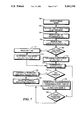
- FIGS. 7 is a flow diagram describing the operation of the simulcast transmission system providing clock synchronization in accordance with the preferred embodiment of the present invention.
- FIG. 1 is an electrical block diagram of a simulcast transmission system 10 in accordance with the preferred embodiment of the present invention.
- the system 10 includes a control station 12 for controlling the distribution of system timing signals used for transmission station clock synchronization and message transmission timing, a communication satellite 14, and a plurality of transmission stations, of which transmission stations 16 and 18 are shown for example only.
- the control station includes a paging terminal 20 which is used to process message information received over the public switched telephone network, PSTN, and to distribute such information, or data, to the plurality of transmission stations 16, 18 for transmission to selective call receivers, such as display pager 19, which is operational in the system.
- the operation of paging terminal 20 for collecting, processing and distributing message information is well known in the art.
- a master timing means, or clock, 22 is coupled to the paging terminal 20 and generates the system timing signals which are used to control the distribution of the message information, or data, and the distribution of synchronization information, as will be further described below.
- the paging terminal 20 couples to a satellite up-link transmitter 24 which transmits the system timing signals to the satellite 14 which then responds to receiving the system timing signals by retransmitting the system timing signals throughout the simulcast transmission system 10.
- the control station 12 also includes a satellite receiver 26 which is used to receive the system timing signals transmitted by the satellite 14.
- the system timing signals when received by the satellite receiver 26 are coupled to a comparing means, or comparator 28, which compares the time of arrival of the system timing signals with the time of transmission of the signals in order to establish a time adjustment factor which is then used to synchronize the transmission clocks used throughout the system, as will be further described below.
- the paging terminal 20 also couples to the transmission stations 16, 18 through a communication link 30, such as provided through the public switched telephone network, or through RF or microwave links.
- the communication link 30 enables transmission of the message data between the control station and the transmission stations 16, 18 in a manner well known in the art.
- the communication link 30 can also be provided through the satellite 14 in an alternate embodiment of the present invention.
- the transmission stations 16, 18 include paging base stations 32, 32' which are utilized to transmit the message data throughout the simulcast transmission system in a manner well known in the art.
- Frequency references 34, 34' are provided which are coupled to the paging base station, and are utilized to establish, or control the carrier frequency of transmission of the message data.
- clocks 36, 36' are also coupled to the frequency references 34, 34' which generate local timing signals which are used for controlling the transmission of the data received from the control station 12 as will be described further below.
- Satellite receivers 38, 38' are used to receive the system timing signals re-transmitted by the satellite 14.
- the system timing signals received by the satellite receivers 38, 38' are coupled to a comparing means, such as comparators 40, 40', which compare the time adjustment factor information established at the control station with the current time indicated by the clocks 36, 36' at each transmission station.
- the time adjustment factor information enables the transmission stations to correct the clock time differences between the control station and the individual transmission station transmission clocks 36, 36'.
- the paging terminal 20 sends clock synchronization information generated by the master clock 22 to the transmission stations 16, 18 using a dedicated satellite channel.
- a time correction factor is generated at the control station in response to receiving the clock synchronization information transmitted as system timing signals by the satellite 14.
- the time correction factor determined at the control station 12 is used by the transmission stations 16, 18, together with system timing signal arrival information measured at each transmission station 16, 18 to calculate the time corrections necessary to synchronize the local clocks 36, 36' at each transmission station with the master clock 22 at the control station 12.
- the simulcast transmission system in accordance with the present invention provides significantly improved control of message transmission time without the complexity or problems associated with audio signal equalization of the prior art systems.
- transmission frequency equalization can also be provided, as will be described below.
- FIG. 2 is a pictorial diagram illustrating the simulcast transmission system in accordance with the preferred embodiment of the present invention.
- the system includes a control station CS, and a plurality of transmission stations, indicated for example, TSA, TSB, TSC and TSN.
- the position and location of the control and transmission stations will depend on the area of coverage provided by the simulcast transmission system and can encompass a relatively small geographic area, such as required to provide coverage to an individual town or city, to a very large geographic area, such as covering a national, or continental transmission system.
- system timing signals generated by the control station CS are transmitted to the satellite, which then re-transmits the signals.
- the control station monitors the actual time of transmission and time of reception of the system timing signals, which enables the time correction factor to be calculated as follows:
- T cf is the computed time correction factor value
- T rec is a second time value corresponding to the time of reception of the system timing signals at the control station CS.
- T xmit is a first time value corresponding to the time of transmission of the system timing signals from the control station CS.
- the difference between the time of transmission and the time of reception provides a complete measurement of all path loss parameters, such as the delay through the satellite up-link transmitter T t , the up-link transmission delay T up , the satellite delay T sat , the down link transmission delay T dn , and the delay through the satellite receiver T rM .
- the satellite utilized in the preferred embodiment of the present invention is a geo-stationary satellite located at the equator, and providing a substantially fixed position relative to points on the surface of the earth, as is well known in the art.
- the time correction factor indicated above can also provide for the measurement of additional transmission variables, such as variation in the satellite position and local geographic atmospheric conditions, just to name a few, as will be described below.
- the system timing signals generated at the control station CS include a timing word which provides identification of a predetermined point in time, or time mark, where the measurement of time of transmission and time of reception are referenced.
- the system timing signals in one embodiment, can include the actual time of transmission relative to the control station CS master clock, and the time correction factor calculated as described above, or in a second embodiment can include an adjusted time of transmission relative to the control station CS master clock which includes the established time correction factor.
- Each transmission station is then able to generate a time adjustment factor, as follows:
- T adjN is the time adjustment factor value for the Nth transmission station.
- T recN is the time value corresponding to the time of reception of the system timings signals at the Nth transmission station.
- T xmit and T cf are as described above.
- the computation as shown above is performed at the transmission stations, although as described above, the factor T xmit +T cf can also be computed at the control station in which case only a single value identified as the adjusted time of transmission need be transmitted. Consequently, the term time correction factor can refer only to T cf in which case the time of transmission T xmit must also be provided, or can refer to T xmit +T cf which includes both the time of transmission and the time correction factor, as defined above.
- the time adjustment factor T adjN calculated as described above provides an indication of the the time indicated by the local clocks relative to the master clock.
- the time adjustment factor T adjN calculated is negative, the local clock time leads the master clock time, indicating the local clock is currently running faster than the master clock at this measurement time interval.
- the time adjustment factor T adjN calculated is positive, the local clock time lags the master clock time, indicating the local clock is currently running slower than the master clock at this measurement time interval. Therefore, the amount and direction of correction of the local transmission station clocks relative to the master control station clock is readily provided.
- the distance between the satellite and the control station CS and transmission stations TS can vary, especially where the distance between the control station CS and the transmission stations TS is large, or where significant differences in the elevation of one station relative to another exist, such as in mountainous terrain. Compensation for variations in the delay of the system timing signals are also accommodated in the preferred embodiment of the present invention by providing a distance correction factor which is stored at each of the transmission stations. It will be appreciated that when the simulcast transmission system covers only a relatively small geographic area and only encompasses a limited number of transmission stations, variations in the distance between the satellite and the individual transmission stations, can be insignificant, and therefore can be ignored.
- the time adjustment factor can be calculated as follows:
- T adjN is the time adjustment factor value for an Nth transmission station including the distance correction factor
- T xmit , T cf and T recN are as described above;
- T distN is the distance correction factor value corresponding to the distance between said satellite and said Nth transmission station.
- the distance correction factor T distN is preferably stored at the individual transmission stations.
- a method of computing time adjustment factors for the individual transmission stations includes for the correction of the transmission delays encountered in the transmission of system timing signals between the control station and the transmission stations, and also provides for certain corrections which can be required due to such variations as due to environmental conditions and satellite position.
- simulcast transmission time equalization is provided.
- additional transmission delays which can affect the adjustment of the local clocks relative to the master clock.
- additional correctable delays include receiver delay differences between transmission stations due to such issues as cabling differences between the receiver antenna and the receiver.
- Other correctable delays include differences in the time of transmission between transmission stations, again due to such issues as cabling differences between the transmitter antenna and the transmitter.
- the additional correctable delays can be handled conventionally using fixed delay elements at each transmission station, although it is preferable that such delays be identified and added into any distance delays, thereby allowing additional adjustment of the time of transmission at the various transmission stations.
- additional timing offsets between transmission stations can be provided to compensate for differing transmitter powers within the system.
- FIG. 3 is a graph depicting the accumulated clock time errors as a function of oscillator stability which is utilized to determine the timing considerations for the periodic synchronization of the local clocks to the master clock in the preferred embodiment of the present invention.
- Data points indicated by box 302 represent maximum accumulated time errors of one microsecond
- data points indicated by box 304 represent maximum accumulated time errors of ten microseconds.
- FIG. 3 is best understood by way of example, such as that provided in TABLE I below which provides a comparison of the frequency of clock synchronization as a function the oscillator stability and the maximum accumulated system time error.
- the run time is a function of both the clock oscillator absolute stability and the maximum accumulated time error allowable between the individual clocks within the system.
- the actual time between system synchronization cycles is actually one-half the run time shown, as two clock oscillators having the same absolute accuracy can accumulate the specified time error relative to each other in one-half the time since one can be drifting in a positive direction, while the other is drifting in a negative direction.
- Clock oscillator accuracies of one part per billion can be readily achieved using high stability oven controlled crystal controlled oscillators.
- One such oscillator is the KXN 1130AA OCXO manufactured by Motorola Inc. can provide a stability of 2 ppb.
- Other oscillator stabilities can be provided by utilizing other oscillator types, such as rubidium frequency standards for stabilities in the 0.01 ppb range.
- FIG. 4 is an electrical block diagram of a transmission station suitable for use in the preferred embodiment of the present invention.
- the transmission stations include a data transmission interconnect 400 which provides an interface between the transmission station and the communication link conveying the incoming messages from the control station.
- the data transmission interconnect 400 can provide any of a number of well known interface structures, such as a telephone interconnect and modem for use with the public switched telephone network, or a direct data input when interfacing with an RF or microwave link.
- the output of the data transmission interface 400 couples to an input of a transmission station controller 402.
- the controller 402 controls the total operation of the transmission station, performing such control operations as controlling the reception of data from the control station, controlling the reception of system timing signals from the satellite, controlling the time synchronization of the local clock, and controlling the transmission of the data received from the control station.
- the controller 402 can be implemented using a microcomputer, such as an MC68030 microcomputer, or a digital signal processor, such as a DSP 65000 digital signal processor, both of which are manufactured by Motorola, Inc, or other microprocessors or digital signal processors.
- the choice of microcomputer or digital signal processor is dependent upon the level of signal processing to be ultimately handled by the controller 402.
- Also coupled to the controller 402 is a memory 404 which is used to store the data received from the control station prior to data transmission.
- the memory 404 can be any suitable form of random access memory, such as integrated dynamic random access memory (DRAM), a hard disk drive, or a combination thereof, just to name a few.
- the memory 404 can also include a read only memory section, such as provided by an electrically erasable programmable read only memory which is used to store routines used by the microcomputer or DSP to control transmission station operation, and which is also used to store the time correction factor for distance from the satellite, as previously described above.
- One output of controller 402 is coupled to an input of encoder 406 which encodes the data recovered for transmission into one of a number of signaling protocols, such as the POCSAG signaling format or the Golay Sequential Code signaling format, although it will be appreciated that any other signaling protocol could be encoded as well.
- the output of the encoder 406 is coupled to the modulation input of the transmitter voltage controlled oscillator 408 which modulates the VCO 408 in a manner well known in the art. It will be appreciated that the controller and clock outputs can also be coupled to other types of modulators, such as a direct digital synthesized modular, as well.
- the output of the VCO 408 couples the modulated carrier signal to the transmitter which then amplifies the signal to a suitable power level for transmission.
- the satellite receiver 412 which is used to receive the system timing signals, as described above.
- the output of the satellite receiver is coupled to an input of the controller 402 which monitors the received timing word to detect the synchronization time mark.
- the controller Upon detection of the synchronization time mark, the controller recovers the current time generated by the local clock 414, and further controls the reception of the time correction factor information generated at the control station.
- the controller includes a means for comparing, such as a comparator or the arithmetic logic unit of the microcomputer or DSP, and compares the current, or local time value, with the received time correction factor, and when necessary recovers the distance correction factor from the memory 404 to derive the time adjustment factor used to correct the local clock.
- the local clock 414 is preferably a real time clock which comprises a count accumulator 418, which is preferably a frequency divider for dividing the clock oscillator output of frequency reference 422, although it will be appreciated other well known techniques would be required to generate non-integer frequency rates from the reference.
- the output of the count accumulator is decoded by clock circuit 420 to generate local timing signals, and more particularly, which generates the predetermined time intervals between clock synchronization cycles, and the particular clock timing signals used to control the operation of the transmission station.
- a real time clock output is also generated which is used to trigger the start of data transmission at the predetermined batch transmission start times to be described below.
- the local clock can alternately be implemented as a non-real time clock using dividers, as described above, to generate the required timing signals with a portion of the dividers forming the count accumulator 418 and functioning as an interval timer, the period of which represents the maximum time interval between clock synchronization cycles.
- the time represented by the count accumulator 418 is advanced or retarded depending upon the time adjustment signal generated via a clock adjust output which is coupled to an adjustment input of the count accumulator 418.
- a second output 424 of the controller 402 couples the clock adjustment information to the input of a reference frequency correction means 426 and is used to provide maintenance of the clock accuracy by compensating for the aging of the oscillator, which for an ovenized crystal controlled oscillator such as the KXN1130AA is ⁇ 30 parts per billion per year.
- the reference frequency correction means includes frequency control latches 428 which are used to store the clock adjustment information between clock synchronization events.
- the output of the frequency control latches is coupled to an input of a digital to analog converter which converts the digital frequency adjustment information into an analog adjustment signal which is coupled to an adjustment input of the frequency reference 422.
- the D/A converter 430 has a twelve bit resolution to provide the necessary resolution for correction of the reference frequency.
- the clock oscillator and transmitter frequency reference 422 is preferably an ovenized voltage controlled crystal oscillator (OVXCO) for use in the transmission stations which would provide clock synchronization intervals of on the order of eight and one-half minutes, as described above.
- the ovenized voltage controlled crystal oscillator (OVXCO) also provides a frequency reference output which is coupled to a second input of the VCO 408, as shown.
- the time interval between frequency compensation events to compensate for aging can be significantly longer than required to correct clock error.
- the frequency compensation can be provided at significantly longer time intervals between compensation events, such as daily, weekly, or even monthly as required.
- FIG. 5 is an electrical block diagram of the control station 12.
- the control station 12 includes a telephone interface 500 which is coupled to the public switched telephone network over which message information is received from one or more input devices, such as a telephone 502, or data entry devices.
- a paging controller or other controller such as utilized in queued transmission communication systems 504, is coupled to the telephone interface 500 and controls the processing of the message information as the information is received.
- a subscriber list memory is provided which stores information identifying the active subscribers belonging to the system, pager addresses and any other information which is required to identify the subscriber's receiver or the receiver's operation.
- the paging controller 504 routes the message information to a message queue in an active page file memory 508 where the message information is temporarily stored prior to distribution to the transmission stations.
- the message information stored in the active page file is recovered by the paging controller 504 and is processed by a protocol encoder 510 which encodes the message information in a format suitable for transmission.
- the output of the protocol encoder 510 is coupled to a transmitter interface 512 which then couples the encoded message information to the respective communication link for distribution to the transmitter stations.
- the operation of the control station as described above for receiving, processing and distributing message information, such as used in paging, and is well known in the art.
- a clock oscillator 514 generates timing information which is coupled to a count accumulator 516, which together with the clock 518 is utilized to generate the system timing signals.
- the count accumulator 516 provides an interval timer function, as described above, which indicates the occurrence of the next synchronization cycle.
- the paging controller formats a synchronization packet which includes a timing word and the current time of transmission which is retrieved from the master clock 518.
- the timing word and time of transmission information are coupled by the paging controller 504 to a transmitter interface 512 which couples the information to the up-link transmitter.
- Information present on the satellite channel is monitored by the satellite receiver 522 which couples the information to the paging controller 504 through receiver interface 524.
- the time of reception is retrieved from the master clock and compared with the time of transmission to determine the time correction factor which is then distributed to the transmissions stations as described above.
- FIG. 6 is a timing diagram illustrating the operation of the simulcast transmission system in accordance with the preferred embodiment of the present invention.
- a data channel is provided for the periodic distribution of message information stored in the active page file memory of the control station to the "store and forward" memory of the transmission stations.
- the information provided over the data channel includes preferably a batch transmission time during time interval 602, and batch data transmission during time control 604.
- Time interval 606 represents a non-transmission time interval which can occur because of the different distances which exist between the control station and the transmission stations, and also is representative of the difference in data transmission rates which are provided over the data channel versus the paging channel, such as, for example, 1200 bps (bits per second) on the paging channel versus 6000 bps on the data channel.
- a paging channel shown in FIG. 6B, provides for the periodic transmission of the batch data during time interval 610.
- a non-transmission time interval 612 occurs because the transmission start time word is not transmitted and also allow for any system delay which is required prior to the start of the next batch transmission.
- the batch data such as the batch data transmission during time interval 604 arrives at the transmission station before the start of transmission and is stored.
- the batch transmission during time interval 614 on the paging channel would represent the transmission of a previously stored batch such as received during time interval 604.
- the total transmission time between synchronization events is determined by the stability of the transmission station clocks, as described above.
- a synchronization packet shown in FIG. 6C is transmitted on the satellite channel 612 and includes a timing word transmitted during time interval 614, a master clock time transmitted during time interval 616 and time correction factor transmitted during time interval 618 as previously described above, or in the alternate the adjusted master clock time of transmission during time interval 626, also as described above.
- the transmitted synchronization packet containing information transmitted at time interval are received at the transmission stations, and are delayed in time due to the satellite up-link and down-link transmission times.
- the local clock value is retrieved as described above.
- the local clock value recovered is then compared with the received master clock time of transmission value during time interval 616' and the time correction factor value during time interval 618', or in the alternate, the adjusted master clock time of transmission during time interval 626, in order to determine the local clock time adjustment factor.
- the time of occurrence of the actual clock realignment is not critical and the clock synchronization can be performed simultaneous to the transmission of the data, with the time accumulator value being incrementally retarded or advanced, as will be described further below.
- the accumulated time error between the control station and the transmission stations will be greater than the maximum allowable time error, even though the accumulated time error between transmission stations is within the maximum allowable accumulated time error. This would occur whenever the stations are told to realign to a clock time outside the allowable clock error.
- the clock is adjusted in two steps.
- the time to the next data sample output is adjusted by the time correction factor.
- the time is instantaneously changed to the adjusted master time. It is assumed that the time adjustment factor is smaller than the data sample rate.
- the advantage of keeping accurate time at the control provides for minimizing the amount of data that must be stored at the stations to assure that the stations always have the data before transmission must start.
- the measurement of the time correction factor at the control and the use of the control as the master clock provide the means to assure that the control clock has the least relative error possible.
- any station may be used as the master as long as communication can be provided to all other clocks in the system and the satellite transmitted is located at that site.
- measurement of the time correction factor may be omitted and an approximate fixed number substituted adding only to the uncertainty of time of data arrival at the stations from the control due to the error of the fixed number and the variations which the measurement had accounted for as previously described.
- time interval 612 would represent an actual non-transmission time interval during which all transmission station clocks are abruptly readjusted to the new time values prior to the next batch transmission start time.
- FIG. 7 is a flow chart describing the clock synchronization operation at the transmission stations. As shown, the transmission stations receive the timing word at step 700, and at the time mark indicated by the timing word, the time of reception T rec is retrieved from the local clock at step 702.
- steps 704 and 706 can also be combine into a single step when the adjusted master clock transmission time is transmitted.
- steps 704 and 706 can also be combine into a single step when the adjusted master clock transmission time is transmitted.
- the value of the distance correction is recovered from memory, at step 710, and the clock error is calculated, as shown at step 712.
- the clock error is calculated, as shown at step 714.
- the local clocks are incrementally adjusted at step 716 in the background of the data transmission.
- the transmission station again continues the batch transmission at the next data sample at step 724 or begins the next data batch transmission at step 724. If the clock adjustment is not complete at step 726, steps 716 through 724 are repeated. When the clock adjustment is complete at step 726, the transmission station continues transmitting the next data samples at step 724.
- synchronization timing information generated at the control station is periodically transmitted to the transmission stations, enabling the transmission station to periodically update the local clocks relative to the master clock at the control station.
- the synchronization timing information sent to each transmission station includes the master clock time (either the time in real time, or those bits significant in determining time differences, such as when an interval timer, or the like, is employed for the master and local clocks) which was recovered at the synchronization time mark.
- the time correction factor is included in the synchronization timing information. The time correction factor is needed to correct for changes in the round trip time delay up to the satellite and back to the ground, and enables the transmission station local clocks to be precisely synchronized with the master clock.
- the synchronization time mark is a predetermined position in the received bit stream of the timing word which is used to trigger the recovery of the time of reception at the control station, and the current time at the transmission stations.
Abstract
A control station 12 initiates a system timing signal transmission which is re-transmitted from a satellite 14. In response to receiving the system timing signal, the control station 12 then generates a time correction factor which is distributed to a plurality of transmission stations 16, 18. The transmission stations 16, 18 in response to receiving the system timing signal transmission and the time correction factor distributed from the control station 12 generate a time adjustment factor which is used to correct the local transmission clocks 36, 36', thereby providing time synchronization of data transmissions generated from the transmission stations 16, 18.
Description
This application is being filed of even date with related U.S. patent application Ser. No. 07/771,577 to Goreham et al. entitled "Simulcast Synchronization and Equalization System and Method Therefor".
1. Field of the Invention
The present invention relates generally to the field of simulcast transmission systems, and more particularly to a simulcast system providing system clock synchronization and carrier frequency equalization.
2. Description of the Prior Art
The primary requirement for effective operation of simulcast transmission systems, such as used in simulcast paging systems, is to minimize the difference in audio phase delay in signals originating from two different transmission stations when received at the paging receiver. The audio phase delay can be minimized by requiring that different transmission stations transmit the same paging information at precisely the same point in time. Prior art paging systems have typically concentrated on equalizing the transmission path delay, including such elements as telephone lines, microwave links or RF links, which were used to connect the paging terminal to the transmission stations. In order to achieve such equalization of the transmission path delay, delay elements were introduced into the transmission path of those transmission stations closest to the source, or origin of the signal transmission, thereby providing a substantially uniform transmission path delay for all transmission stations throughout the system. Unfortunately, once such simulcast transmission systems were equalized, there was no guarantee the equalization would remain constant throughout any particular transmission period, because several of the transmission elements, particularly the telephone lines when they were not dedicated, were subject to variation throughout the transmission period.
In order to overcome the deficiencies noted above, several prior art simulcast transmission systems have utilized which has become known as a "store and forward" transmission technique, wherein the transmission data is stored at the individual transmission stations within the system and then broadcast, or forwarded, from all transmission stations at a predetermined time. Equalization of such systems have relied on the use of global positioning satellite systems which provided the accurate timing control necessary to control the timing of transmissions throughout the system. While such systems using global positioning satellites have proved effective in providing control of the transmission timing requirements, the advantages are provided at a substantial cost differential as compared to conventional simulcast transmission equalization systems.
There is a need to provide simulcast system equalization capability to without the use of a global positioning satellite system.
In accordance with one aspect of the present invention, a simulcast transmission system comprises a control station and a plurality of transmission stations. The control station comprises a first time generating means for generating system timing signals, a means for transmitting the system timing signals, a means for generating a time correction factor, and a means for distributing the time correction factor to the plurality of transmission stations. The plurality of transmission stations comprise a second time generating means for generating local timing signals, a means responsive to local timing signals for transmitting data, a means for receiving the transmitted system timing signals, a means for receiving the time correction factor, a means for comparing the received system timing signals and time correction factor with the local timing signals to generate a time adjustment factor signal, and a means which is responsive to the time adjustment factor signal for adjusting the timing of the second time generating means.
In accordance with another aspect of the present invention, a transmission station is provided which is capable of providing simulcast data transmission in a multiple transmission station communication system which has a control station for generating and distributing a time correction factor in response to receiving a transmitted system timing signal to the transmission station. The transmission station comprises a time generating means for generating local timing signals, a means responsive to local timing signals for transmitting data, a means for receiving the transmitted system timing signals, a means for receiving the time correction factor, a means for comparing the received system timing signals and time correction factor with the local timing signals to generate a time adjustment factor, and a means responsive to the time adjustment factor signal for adjusting the timing of said time generating means.
FIG. 1 is an electrical block diagram of a simulcast transmission system providing clock synchronization in accordance with the preferred embodiment of the present invention.
FIG. 2 is a timing diagram illustrating the timing considerations required to provide clock synchronization for the simulcast transmission system in accordance with the preferred embodiment of the present invention.
FIG. 3 is a graph depicting the accumulated clock time errors as a function of oscillator stability.
FIG. 4 is an electrical block diagram of a transmission station suitable for use with the preferred embodiment of the present invention.
FIG. 5 is an electrical block diagram of a control station suitable for use with the preferred embodiment of the present invention.
FIGS. 6A-D are pictorial diagrams illustrating the system transmissions in accordance with the preferred embodiment of the present invention.
FIGS. 7 is a flow diagram describing the operation of the simulcast transmission system providing clock synchronization in accordance with the preferred embodiment of the present invention.
Referring to the diagrams, FIG. 1 is an electrical block diagram of a simulcast transmission system 10 in accordance with the preferred embodiment of the present invention. The system 10 includes a control station 12 for controlling the distribution of system timing signals used for transmission station clock synchronization and message transmission timing, a communication satellite 14, and a plurality of transmission stations, of which transmission stations 16 and 18 are shown for example only. The control station includes a paging terminal 20 which is used to process message information received over the public switched telephone network, PSTN, and to distribute such information, or data, to the plurality of transmission stations 16, 18 for transmission to selective call receivers, such as display pager 19, which is operational in the system. The operation of paging terminal 20 for collecting, processing and distributing message information is well known in the art. A master timing means, or clock, 22 is coupled to the paging terminal 20 and generates the system timing signals which are used to control the distribution of the message information, or data, and the distribution of synchronization information, as will be further described below. The paging terminal 20 couples to a satellite up-link transmitter 24 which transmits the system timing signals to the satellite 14 which then responds to receiving the system timing signals by retransmitting the system timing signals throughout the simulcast transmission system 10. The control station 12 also includes a satellite receiver 26 which is used to receive the system timing signals transmitted by the satellite 14. The system timing signals when received by the satellite receiver 26 are coupled to a comparing means, or comparator 28, which compares the time of arrival of the system timing signals with the time of transmission of the signals in order to establish a time adjustment factor which is then used to synchronize the transmission clocks used throughout the system, as will be further described below.
The paging terminal 20 also couples to the transmission stations 16, 18 through a communication link 30, such as provided through the public switched telephone network, or through RF or microwave links. The communication link 30 enables transmission of the message data between the control station and the transmission stations 16, 18 in a manner well known in the art. As will become more apparent in the description to follow, and unlike the prior art simulcast transmission systems which used GPS satellites for timing control, the communication link 30 can also be provided through the satellite 14 in an alternate embodiment of the present invention.
The transmission stations 16, 18 include paging base stations 32, 32' which are utilized to transmit the message data throughout the simulcast transmission system in a manner well known in the art. Frequency references 34, 34' are provided which are coupled to the paging base station, and are utilized to establish, or control the carrier frequency of transmission of the message data. Also coupled to the frequency references 34, 34' are clocks 36, 36' which generate local timing signals which are used for controlling the transmission of the data received from the control station 12 as will be described further below. Satellite receivers 38, 38' are used to receive the system timing signals re-transmitted by the satellite 14. The system timing signals received by the satellite receivers 38, 38' are coupled to a comparing means, such as comparators 40, 40', which compare the time adjustment factor information established at the control station with the current time indicated by the clocks 36, 36' at each transmission station. The time adjustment factor information enables the transmission stations to correct the clock time differences between the control station and the individual transmission station transmission clocks 36, 36'.
Operation of the simulcast transmission system in accordance with the preferred embodiment of the present invention can be summarized as follows. The paging terminal 20 sends clock synchronization information generated by the master clock 22 to the transmission stations 16, 18 using a dedicated satellite channel. A time correction factor is generated at the control station in response to receiving the clock synchronization information transmitted as system timing signals by the satellite 14. The time correction factor determined at the control station 12 is used by the transmission stations 16, 18, together with system timing signal arrival information measured at each transmission station 16, 18 to calculate the time corrections necessary to synchronize the local clocks 36, 36' at each transmission station with the master clock 22 at the control station 12. By periodically resynchronizing the local clocks with the master clock, the simulcast transmission system in accordance with the present invention provides significantly improved control of message transmission time without the complexity or problems associated with audio signal equalization of the prior art systems. In addition, transmission frequency equalization can also be provided, as will be described below.
Reference is directed to FIG. 2 which is a pictorial diagram illustrating the simulcast transmission system in accordance with the preferred embodiment of the present invention. As shown in FIG. 2, the system includes a control station CS, and a plurality of transmission stations, indicated for example, TSA, TSB, TSC and TSN. The position and location of the control and transmission stations will depend on the area of coverage provided by the simulcast transmission system and can encompass a relatively small geographic area, such as required to provide coverage to an individual town or city, to a very large geographic area, such as covering a national, or continental transmission system.
As described above, system timing signals generated by the control station CS are transmitted to the satellite, which then re-transmits the signals. The control station monitors the actual time of transmission and time of reception of the system timing signals, which enables the time correction factor to be calculated as follows:
T.sub.cf =T.sub.rec -T.sub.xmit
where
Tcf is the computed time correction factor value;
Trec is a second time value corresponding to the time of reception of the system timing signals at the control station CS; and
Txmit is a first time value corresponding to the time of transmission of the system timing signals from the control station CS.
It will be apparent from the description above that the difference between the time of transmission and the time of reception provides a complete measurement of all path loss parameters, such as the delay through the satellite up-link transmitter Tt, the up-link transmission delay Tup, the satellite delay Tsat, the down link transmission delay Tdn, and the delay through the satellite receiver TrM.
The satellite utilized in the preferred embodiment of the present invention is a geo-stationary satellite located at the equator, and providing a substantially fixed position relative to points on the surface of the earth, as is well known in the art. Thus the time correction factor indicated above can also provide for the measurement of additional transmission variables, such as variation in the satellite position and local geographic atmospheric conditions, just to name a few, as will be described below.
The system timing signals generated at the control station CS include a timing word which provides identification of a predetermined point in time, or time mark, where the measurement of time of transmission and time of reception are referenced. The system timing signals, in one embodiment, can include the actual time of transmission relative to the control station CS master clock, and the time correction factor calculated as described above, or in a second embodiment can include an adjusted time of transmission relative to the control station CS master clock which includes the established time correction factor. Each transmission station is then able to generate a time adjustment factor, as follows:
T.sub.adjN =(T.sub.xmit +T.sub.cf)-T.sub.recN
where
TadjN is the time adjustment factor value for the Nth transmission station; and
TrecN is the time value corresponding to the time of reception of the system timings signals at the Nth transmission station.
Txmit and Tcf are as described above. When Txmit and Tcf are transmitted separately, the computation as shown above is performed at the transmission stations, although as described above, the factor Txmit +Tcf can also be computed at the control station in which case only a single value identified as the adjusted time of transmission need be transmitted. Consequently, the term time correction factor can refer only to Tcf in which case the time of transmission Txmit must also be provided, or can refer to Txmit +Tcf which includes both the time of transmission and the time correction factor, as defined above.
The time adjustment factor TadjN calculated as described above provides an indication of the the time indicated by the local clocks relative to the master clock. When the time adjustment factor TadjN calculated is negative, the local clock time leads the master clock time, indicating the local clock is currently running faster than the master clock at this measurement time interval. And when the time adjustment factor TadjN calculated is positive, the local clock time lags the master clock time, indicating the local clock is currently running slower than the master clock at this measurement time interval. Therefore, the amount and direction of correction of the local transmission station clocks relative to the master control station clock is readily provided.
As will be appreciated by one of skill in the art, the distance between the satellite and the control station CS and transmission stations TS can vary, especially where the distance between the control station CS and the transmission stations TS is large, or where significant differences in the elevation of one station relative to another exist, such as in mountainous terrain. Compensation for variations in the delay of the system timing signals are also accommodated in the preferred embodiment of the present invention by providing a distance correction factor which is stored at each of the transmission stations. It will be appreciated that when the simulcast transmission system covers only a relatively small geographic area and only encompasses a limited number of transmission stations, variations in the distance between the satellite and the individual transmission stations, can be insignificant, and therefore can be ignored.
When the distance between the satellite and the transmission stations becomes significant, the time adjustment factor can be calculated as follows:
T.sub.adjN =(T.sub.xmit +T.sub.cf)+T.sub.distN -T.sub.recN
where
TadjN is the time adjustment factor value for an Nth transmission station including the distance correction factor,
Txmit, Tcf and TrecN are as described above; and
TdistN is the distance correction factor value corresponding to the distance between said satellite and said Nth transmission station. The distance correction factor TdistN is preferably stored at the individual transmission stations.
In summary, a method of computing time adjustment factors for the individual transmission stations has been provided above. The method includes for the correction of the transmission delays encountered in the transmission of system timing signals between the control station and the transmission stations, and also provides for certain corrections which can be required due to such variations as due to environmental conditions and satellite position. By periodically adjusting the local clock times relative to the master clock time, as described above, simulcast transmission time equalization is provided.
While not specifically shown in the equations presented above, it will be appreciated that there can be additional transmission delays which can affect the adjustment of the local clocks relative to the master clock. Examples of such additional correctable delays include receiver delay differences between transmission stations due to such issues as cabling differences between the receiver antenna and the receiver. Other correctable delays include differences in the time of transmission between transmission stations, again due to such issues as cabling differences between the transmitter antenna and the transmitter. The additional correctable delays can be handled conventionally using fixed delay elements at each transmission station, although it is preferable that such delays be identified and added into any distance delays, thereby allowing additional adjustment of the time of transmission at the various transmission stations. In addition, additional timing offsets between transmission stations can be provided to compensate for differing transmitter powers within the system.
Reference is now directed to FIG. 3 which is a graph depicting the accumulated clock time errors as a function of oscillator stability which is utilized to determine the timing considerations for the periodic synchronization of the local clocks to the master clock in the preferred embodiment of the present invention. Data points indicated by box 302 represent maximum accumulated time errors of one microsecond, while data points indicated by box 304 represent maximum accumulated time errors of ten microseconds. FIG. 3 is best understood by way of example, such as that provided in TABLE I below which provides a comparison of the frequency of clock synchronization as a function the oscillator stability and the maximum accumulated system time error.
              TABLE I
______________________________________
Clock Oscillator
            Max Accumulated         Sync
Accuracy (ppb)
            Time Error (μS)
                          Run Time  Interval
______________________________________
.1          1             ˜2.8
                                 hrs  1.4 hrs.
.1          10            ˜28
                                 hrs  14  hrs.
1           1             ˜17
                                 mins 8.5 min.
1           10            ˜2.8
                                 hrs  1.4 hrs.
______________________________________
As shown in TABLE I, the run time is a function of both the clock oscillator absolute stability and the maximum accumulated time error allowable between the individual clocks within the system. The actual time between system synchronization cycles is actually one-half the run time shown, as two clock oscillators having the same absolute accuracy can accumulate the specified time error relative to each other in one-half the time since one can be drifting in a positive direction, while the other is drifting in a negative direction. It will be appreciated that the times represented are only approximate, and that the actual time is computed as shown below by dividing the Maximum Accumulated Time Error in μS by the Clock Oscillator Absolute Stability in ppb to determine the drift time in seconds which is then converted to minutes and hours in a manner well known in the art. ##EQU1##
Clock oscillator accuracies of one part per billion can be readily achieved using high stability oven controlled crystal controlled oscillators. One such oscillator is the KXN 1130AA OCXO manufactured by Motorola Inc. can provide a stability of 2 ppb. Other oscillator stabilities can be provided by utilizing other oscillator types, such as rubidium frequency standards for stabilities in the 0.01 ppb range.
FIG. 4 is an electrical block diagram of a transmission station suitable for use in the preferred embodiment of the present invention. As shown in FIG. 4, the transmission stations include a data transmission interconnect 400 which provides an interface between the transmission station and the communication link conveying the incoming messages from the control station. The data transmission interconnect 400 can provide any of a number of well known interface structures, such as a telephone interconnect and modem for use with the public switched telephone network, or a direct data input when interfacing with an RF or microwave link. The output of the data transmission interface 400 couples to an input of a transmission station controller 402. The controller 402 controls the total operation of the transmission station, performing such control operations as controlling the reception of data from the control station, controlling the reception of system timing signals from the satellite, controlling the time synchronization of the local clock, and controlling the transmission of the data received from the control station. The controller 402 can be implemented using a microcomputer, such as an MC68030 microcomputer, or a digital signal processor, such as a DSP 65000 digital signal processor, both of which are manufactured by Motorola, Inc, or other microprocessors or digital signal processors. The choice of microcomputer or digital signal processor is dependent upon the level of signal processing to be ultimately handled by the controller 402. Also coupled to the controller 402 is a memory 404 which is used to store the data received from the control station prior to data transmission. The memory 404 can be any suitable form of random access memory, such as integrated dynamic random access memory (DRAM), a hard disk drive, or a combination thereof, just to name a few. The memory 404 can also include a read only memory section, such as provided by an electrically erasable programmable read only memory which is used to store routines used by the microcomputer or DSP to control transmission station operation, and which is also used to store the time correction factor for distance from the satellite, as previously described above. One output of controller 402 is coupled to an input of encoder 406 which encodes the data recovered for transmission into one of a number of signaling protocols, such as the POCSAG signaling format or the Golay Sequential Code signaling format, although it will be appreciated that any other signaling protocol could be encoded as well. The output of the encoder 406 is coupled to the modulation input of the transmitter voltage controlled oscillator 408 which modulates the VCO 408 in a manner well known in the art. It will be appreciated that the controller and clock outputs can also be coupled to other types of modulators, such as a direct digital synthesized modular, as well. The output of the VCO 408 couples the modulated carrier signal to the transmitter which then amplifies the signal to a suitable power level for transmission.
Also coupled to the controller 402 is the satellite receiver 412 which is used to receive the system timing signals, as described above. The output of the satellite receiver is coupled to an input of the controller 402 which monitors the received timing word to detect the synchronization time mark. Upon detection of the synchronization time mark, the controller recovers the current time generated by the local clock 414, and further controls the reception of the time correction factor information generated at the control station. The controller includes a means for comparing, such as a comparator or the arithmetic logic unit of the microcomputer or DSP, and compares the current, or local time value, with the received time correction factor, and when necessary recovers the distance correction factor from the memory 404 to derive the time adjustment factor used to correct the local clock.
The local clock 414 is preferably a real time clock which comprises a count accumulator 418, which is preferably a frequency divider for dividing the clock oscillator output of frequency reference 422, although it will be appreciated other well known techniques would be required to generate non-integer frequency rates from the reference. The output of the count accumulator is decoded by clock circuit 420 to generate local timing signals, and more particularly, which generates the predetermined time intervals between clock synchronization cycles, and the particular clock timing signals used to control the operation of the transmission station. A real time clock output is also generated which is used to trigger the start of data transmission at the predetermined batch transmission start times to be described below. The local clock can alternately be implemented as a non-real time clock using dividers, as described above, to generate the required timing signals with a portion of the dividers forming the count accumulator 418 and functioning as an interval timer, the period of which represents the maximum time interval between clock synchronization cycles. In either instance, the time represented by the count accumulator 418 is advanced or retarded depending upon the time adjustment signal generated via a clock adjust output which is coupled to an adjustment input of the count accumulator 418.
A second output 424 of the controller 402 couples the clock adjustment information to the input of a reference frequency correction means 426 and is used to provide maintenance of the clock accuracy by compensating for the aging of the oscillator, which for an ovenized crystal controlled oscillator such as the KXN1130AA is ±30 parts per billion per year. The reference frequency correction means includes frequency control latches 428 which are used to store the clock adjustment information between clock synchronization events. The output of the frequency control latches is coupled to an input of a digital to analog converter which converts the digital frequency adjustment information into an analog adjustment signal which is coupled to an adjustment input of the frequency reference 422. In the preferred embodiment of the present invention, the D/A converter 430 has a twelve bit resolution to provide the necessary resolution for correction of the reference frequency. The clock oscillator and transmitter frequency reference 422 is preferably an ovenized voltage controlled crystal oscillator (OVXCO) for use in the transmission stations which would provide clock synchronization intervals of on the order of eight and one-half minutes, as described above. The ovenized voltage controlled crystal oscillator (OVXCO) also provides a frequency reference output which is coupled to a second input of the VCO 408, as shown.
Because the rate of aging is significantly less than the time error accumulated, the time interval between frequency compensation events to compensate for aging can be significantly longer than required to correct clock error. As a result, while clock error compensation is periodically required at relatively short time intervals, the frequency compensation can be provided at significantly longer time intervals between compensation events, such as daily, weekly, or even monthly as required.
Reference is directed to FIG. 5 which is an electrical block diagram of the control station 12. The control station 12 includes a telephone interface 500 which is coupled to the public switched telephone network over which message information is received from one or more input devices, such as a telephone 502, or data entry devices. A paging controller or other controller, such as utilized in queued transmission communication systems 504, is coupled to the telephone interface 500 and controls the processing of the message information as the information is received. A subscriber list memory is provided which stores information identifying the active subscribers belonging to the system, pager addresses and any other information which is required to identify the subscriber's receiver or the receiver's operation. As the message information is received, the paging controller 504 routes the message information to a message queue in an active page file memory 508 where the message information is temporarily stored prior to distribution to the transmission stations. At periodic time intervals, to be described below, the message information stored in the active page file is recovered by the paging controller 504 and is processed by a protocol encoder 510 which encodes the message information in a format suitable for transmission. The output of the protocol encoder 510 is coupled to a transmitter interface 512 which then couples the encoded message information to the respective communication link for distribution to the transmitter stations. The operation of the control station, as described above for receiving, processing and distributing message information, such as used in paging, and is well known in the art.
A clock oscillator 514 generates timing information which is coupled to a count accumulator 516, which together with the clock 518 is utilized to generate the system timing signals. In the preferred embodiment of the present invention, the count accumulator 516 provides an interval timer function, as described above, which indicates the occurrence of the next synchronization cycle. When the next synchronization cycle is indicated by the count accumulator 516, the paging controller formats a synchronization packet which includes a timing word and the current time of transmission which is retrieved from the master clock 518. The timing word and time of transmission information are coupled by the paging controller 504 to a transmitter interface 512 which couples the information to the up-link transmitter. Information present on the satellite channel is monitored by the satellite receiver 522 which couples the information to the paging controller 504 through receiver interface 524. When the timing code word is received and the transition indicating the synchronization time mark is detected, the time of reception is retrieved from the master clock and compared with the time of transmission to determine the time correction factor which is then distributed to the transmissions stations as described above.
Reference is directed to FIG. 6 which is a timing diagram illustrating the operation of the simulcast transmission system in accordance with the preferred embodiment of the present invention. As shown in FIG. 6A, a data channel is provided for the periodic distribution of message information stored in the active page file memory of the control station to the "store and forward" memory of the transmission stations. The information provided over the data channel includes preferably a batch transmission time during time interval 602, and batch data transmission during time control 604. Time interval 606 represents a non-transmission time interval which can occur because of the different distances which exist between the control station and the transmission stations, and also is representative of the difference in data transmission rates which are provided over the data channel versus the paging channel, such as, for example, 1200 bps (bits per second) on the paging channel versus 6000 bps on the data channel.
A paging channel, shown in FIG. 6B, provides for the periodic transmission of the batch data during time interval 610. A non-transmission time interval 612 occurs because the transmission start time word is not transmitted and also allow for any system delay which is required prior to the start of the next batch transmission. It should be noted that when the transmission stations operate in a "store and foreword" mode, the batch data, such as the batch data transmission during time interval 604, arrives at the transmission station before the start of transmission and is stored. The batch transmission during time interval 614 on the paging channel would represent the transmission of a previously stored batch such as received during time interval 604. The total transmission time between synchronization events is determined by the stability of the transmission station clocks, as described above.
During the time that data is being transmitted on the paging channel and message information is distributed to the transmission stations on the data channel, a synchronization packet, shown in FIG. 6C is transmitted on the satellite channel 612 and includes a timing word transmitted during time interval 614, a master clock time transmitted during time interval 616 and time correction factor transmitted during time interval 618 as previously described above, or in the alternate the adjusted master clock time of transmission during time interval 626, also as described above.
As shown in FIG. 6D, the transmitted synchronization packet containing information transmitted at time interval are received at the transmission stations, and are delayed in time due to the satellite up-link and down-link transmission times. When the synchronization packet is received at the transmission stations, and the reception time mark 620 is detected within the timing word during time interval 614', the local clock value is retrieved as described above. The local clock value recovered is then compared with the received master clock time of transmission value during time interval 616' and the time correction factor value during time interval 618', or in the alternate, the adjusted master clock time of transmission during time interval 626, in order to determine the local clock time adjustment factor. As further shown in FIG. 6D, there is generally a variation in the final time of reception of the synchronization packet indicated by time interval 622 at each transmission station due largely to the distance variations between the satellite and transmission stations. Following the reception of the synchronization packet at each of the transmission stations, the local clocks are adjusted, and as shown the earliest transmission stations beginning the clock adjustment at a time indicated by timing line 628, and the latest transmissions stations beginning the clock adjustment at a time indicated by timing line 630. In the preferred embodiment of the present invention, when the stability of the control station and transmission stations clocks are similar, the time deviation between clocks remains within the maximum accumulated time error for the system. The time of occurrence of the actual clock realignment is not critical and the clock synchronization can be performed simultaneous to the transmission of the data, with the time accumulator value being incrementally retarded or advanced, as will be described further below. When a lower stability clock is used at the control station in comparison to the transmission stations, the accumulated time error between the control station and the transmission stations will be greater than the maximum allowable time error, even though the accumulated time error between transmission stations is within the maximum allowable accumulated time error. This would occur whenever the stations are told to realign to a clock time outside the allowable clock error. In the second embodiment, the clock is adjusted in two steps. Starting at a time which could be specified on the satellite channel 706 (not shown; if the spread in time of arrival 622 is small enough, the time could be gated off the time-mark arrival), the time to the next data sample output is adjusted by the time correction factor. At the next data sample, the time is instantaneously changed to the adjusted master time. It is assumed that the time adjustment factor is smaller than the data sample rate.
The advantage of keeping accurate time at the control provides for minimizing the amount of data that must be stored at the stations to assure that the stations always have the data before transmission must start. The measurement of the time correction factor at the control and the use of the control as the master clock provide the means to assure that the control clock has the least relative error possible. However, any station may be used as the master as long as communication can be provided to all other clocks in the system and the satellite transmitted is located at that site. In addition, measurement of the time correction factor may be omitted and an approximate fixed number substituted adding only to the uncertainty of time of data arrival at the stations from the control due to the error of the fixed number and the variations which the measurement had accounted for as previously described.
In a third embodiment, time interval 612 would represent an actual non-transmission time interval during which all transmission station clocks are abruptly readjusted to the new time values prior to the next batch transmission start time. In summary, it is readily possible for those skilled in the art to either adjust the clock simultaneously with the data transmission or to allocate a time period during which the paging channel may not be used to allow a clock adjustment cycle requiring time in excess of the data sample rate. FIG. 7 is a flow chart describing the clock synchronization operation at the transmission stations. As shown, the transmission stations receive the timing word at step 700, and at the time mark indicated by the timing word, the time of reception Trec is retrieved from the local clock at step 702. The time of transmission Txmit of the timing word is then received, at step 704, followed by the time correction factor value Tcf, at step 706. As described above steps 704 and 706 can also be combine into a single step when the adjusted master clock transmission time is transmitted. When a distance correction is required, at step 708, the value of the distance correction is recovered from memory, at step 710, and the clock error is calculated, as shown at step 712. When the distance correction is not necessary, at step 708, such as when a particular transmission station is at the same distance from the satellite as the control station, or that all transmission stations with the geographic area are at substantially the same distance, the clock error is calculated, as shown at step 714. Following the calculation of the clock error, the local clocks are incrementally adjusted at step 716 in the background of the data transmission. Following the incremental adjustment, the transmission station again continues the batch transmission at the next data sample at step 724 or begins the next data batch transmission at step 724. If the clock adjustment is not complete at step 726, steps 716 through 724 are repeated. When the clock adjustment is complete at step 726, the transmission station continues transmitting the next data samples at step 724.
In summary, synchronization timing information generated at the control station is periodically transmitted to the transmission stations, enabling the transmission station to periodically update the local clocks relative to the master clock at the control station. The synchronization timing information sent to each transmission station includes the master clock time (either the time in real time, or those bits significant in determining time differences, such as when an interval timer, or the like, is employed for the master and local clocks) which was recovered at the synchronization time mark. Also included in the synchronization timing information is the time correction factor established at the control station. The time correction factor is needed to correct for changes in the round trip time delay up to the satellite and back to the ground, and enables the transmission station local clocks to be precisely synchronized with the master clock. The synchronization time mark is a predetermined position in the received bit stream of the timing word which is used to trigger the recovery of the time of reception at the control station, and the current time at the transmission stations.
Claims (35)
1. A simulcast transmission system having means for time synchronizing the transmission of data signals therefrom, comprising:
a control station comprising first time generating means for generating system timing signals and for transmitting the same, means for receiving the transmitted system timing signals, means for comparing the transmitted and received system timing signals to generate a time correction factor signal in response thereto, and means for distributing the time correction factor signal to a plurality of transmission stations; and
each of said plurality of transmission stations comprising second time generating means for generating local timing signals, means responsive to local timing signals for transmitting the data signals, means for receiving the transmitted system timing signals, means for receiving the time correction factor signal, means for comparing the received system timing signals and time correction factor signal with the local timing signals to generate a time adjustment factor signal, and means responsive to the time adjustment factor signal for adjusting the timing of said second time generating means.
2. The simulcast transmission system according to claim 1, wherein said first time generating means comprises:
means for generating frequency reference signals; and
master clock means, responsive to the frequency reference signals for generating the system timing signals.
3. The simulcast transmission system according to claim 1, wherein said second time generating means comprises:
means for generating frequency reference signals; and
local clock means, responsive to the frequency reference signals for generating the local timing signals.
4. The simulcast transmission system according to claim 1, wherein said means for transmitting the system timing signals comprises:
satellite up-link transmitter means for transmitting the system timing signals to a satellite, said satellite having satellite receiving means for receiving the transmitted system timing signals, and satellite transmitter means, coupled to said satellite receiving means, for re-transmitting the received system timing signals.
5. The simulcast transmission system according to claim 4, wherein said means for transmitting the system timing signals further transmits the data signals and data transmission start time signals.
6. The simulcast transmission system according to claim 1, wherein said means for comparing the transmitted and received system timing signals comprises a microcomputer.
7. The simulcast transmission system according to claim 6, wherein the time correction factor signal includes a time correction factor value calculated by said microcomputer using
T.sub.cf =T.sub.rec -T.sub.xmit
where
Tcf is the time correction factor value,
Trec is a second time value corresponding to the time of reception of the system timing signals, and
Txmit is a first time value corresponding to the time of transmission of the system timing signals.
8. The simulcast transmission system according to claim 1, wherein said means for comparing the received system timing signals and time correction factor signal with the local timing signals comprises a microcomputer.
9. The simulcast transmission system according to claim 8, wherein the time adjustment factor signal includes a time adjustment factor value calculated by said microcomputer using
T.sub.adjN =(T.sub.xmit +T.sub.cf)-T.sub.recN
where
TadjN is the time adjustment factor value for an Nth transmission station,
Txmit is the first time value corresponding to the time of transmission of the system timing signals,
Tcf is the time correction factor value, and
TrecN is a time value corresponding to the time of reception of the system timing signals at the Nth transmission station.
10. The simulcast transmission system according to claim 1, wherein the system timing signals include at least timing information corresponding to a predetermined time for the transmission of the data signals from said plurality of transmission stations and synchronization signals which include at least synchronization information identifying a predetermined time mark and data signal transmission time information corresponding thereto.
11. The simulcast transmission system according to claim 10, wherein the synchronization signals re periodically generated.
12. The simulcast transmission system according to claim 1, wherein said means for adjusting the timing of said second time generating means comprises:
means for storing a time adjustment factor value derived by comparing the received system timing signals and time correction factor signal with the local timing signals;
converter means, coupled to said storing means, for converting the stored time adjustment factor value into the time adjustment factor signal.
13. The simulcast transmission system according to claim 12, wherein said time adjustment factor value is a digital information sequence, and wherein said converter means converts the digital information sequence into an analog signal corresponding to the time adjustment factor signal.
14. The simulcast transmission system according to claim 1, wherein said transmissions stations further comprise means for storing a distance correction factor signal, and said means for comparing compares the received system timing signals and time correction factor signal with the local timing signals and a distance correction factor signal to generate the time adjustment factor signal.
15. The simulcast transmission system according to claim 14, wherein said transmissions station further comprises memory means for storing information, and wherein the distance correction factor signal includes a distance correction factor value which is stored in said memory means.
16. The simulcast transmission system according to claim 15, wherein said means for comparing the received system timing signals and time correction factor signal with the local timing signals and a distance correction factor signal comprises a microcomputer.
17. The simulcast transmission system according to claim 16, wherein the time adjustment factor signal includes a time adjustment factor value calculated by said microcomputer using
T.sub.adjN =(T.sub.xmit +T.sub.cf)+T.sub.distN -T.sub.recN
where
TadjN is the time adjustment factor value for an Nth transmission station,
Txmit is the first time value corresponding to the time of transmission of the system timing signals,
Tcf is the time correction factor value,
TdistN is the distance correction factor value corresponding to the distance between said satellite and said Nth transmission station, and
TrecN is a time value corresponding to the time of reception of the system timing signals at the Nth transmission station.
18. A transmission station for use in a simulcast transmission system comprising a plurality of transmission stations which are capable of providing simulcast transmission of data signals, the simulcast transmission system having a control station which is capable of generating system timing signals, and in response thereto generating a time correction factor signal, and for distributing the time correction factor signal to the plurality of transmission stations, said transmission station comprising:
time generating means for generating local timing signals:
means, responsive to local timing signals, for transmitting the data signals;
means for receiving the transmitted system timing signals;
means for receiving the time correction factor signal;
means for comparing the received system timing signals and the time correction factor signal with the local timing signals to generate a time adjustment factor signal; and
means responsive to the time adjustment factor signal for adjusting the timing of said time generating means.
19. The transmission station according to claim 18, wherein said time generating means comprises:
frequency reference generating means for generating frequency reference signals; and
local clock means, responsive to the frequency reference signals for generating the local timing signals.
20. The transmission station according to claim 19, wherein said means for transmitting the data signals transmits the data signals at a predetermined transmission frequency.
21. The transmission station according to claim 20, wherein the predetermined transmission frequency is established by the frequency reference signals generated.
22. The transmission station according to claim 18, wherein said means for comparing the received system timing signals and the time correction factor signal with the local timing signals comprises a microcomputer.
23. The transmission station according to claim 22, wherein the time adjustment factor signal includes a time adjustment factor value calculated by
T.sub.adj =(T.sub.xmit +T.sub.cf)-T.sub.rec
where
Tadj is the time adjustment factor value calculated for the transmission station,
Txmit is the first time value corresponding to the time of transmission of the system timing signals,
Tcf is the time correction factor value, and
Trec is a time value corresponding to the time of reception of the system timing signals at the transmission station.
24. The transmission station according to claim 18, wherein the system timing signals include at least timing information corresponding to a predetermined time for data signal transmission from said transmission station and synchronization signals which include at least synchronization information identifying a predetermined time mark and data signal transmission time information corresponding thereto.
25. The transmission station according to claim 23, wherein said means for adjusting the timing of said time generating means comprises:
means for storing the time adjustment factor value;
converter means, coupled to said storing means, for converting the stored time adjustment factor value into the time adjustment factor signal.
26. The transmission station according to claim 25, wherein said time adjustment factor value is a digital information sequence, and wherein said converter means converts the digital information sequence into an analog signal corresponding to the time adjustment factor signal.
27. The transmission station according to claim 18 further comprising means for storing a distance correction factor signal, and said means for comparing compares the received system timing signals and time correction factor signal with the local timing signals and a distance correction factor signal to generate the time adjustment factor signal.
28. The transmission station according to claim 27 further comprising memory means for storing information, and wherein the distance correction factor signal includes a distance correction factor value which is stored in said memory means.
29. The transmission station according to claim 28, wherein said means for comparing the received system timing signals and the time correction factor signal with the local timing signals and the distance correction factor signal comprises a microcomputer.
30. The transmission station according to claim 29, wherein the time adjustment factor signal includes a time adjustment factor value calculated by
T.sub.adj =(T.sub.xmit +T.sub.cf)+T.sub.dist -T.sub.rec
where
Tadj is the time adjustment factor value for said transmission station,
Txmit is the first time value corresponding to the time of transmission of the system timing signals,
Tcf is the time correction factor value,
Tdist is the distance correction factor value corresponding to the distance between said satellite and said transmission station, and
Trec is a time value corresponding to the time of reception of the system timing signals at said transmission station.
31. A method of time synchronizing data signal transmissions originating from a plurality of transmission stations operating within a simulcast transmission system, the transmission stations having transmission clocks for controlling the starting time of the data signal transmissions, said method comprising the step of:
generating, at a control station, a time correction factor signal in response to the control station generating and transmitting a system timing signal;
distributing the system timing signal and the time correction factor signal from the control station to the transmission stations;
generating, at the transmission stations, local time adjustment factor signals in response to receiving the system timing signal and the time correction factor signal;
adjusting the transmission clocks at the transmission stations in response to the local time adjustment factor signals generated.
32. The method of time synchronizing data signal transmissions according to claim 31 wherein said step of generating a time correction factor signal at the control station comprises the steps of:
transmitting, from the control station, the system timing signal which includes at least a timing word which provides a time mark indicating a time of transmission of the system timing signal;
receiving the system timing signal including the timing word at the control station to detect the time of reception of the system timing signal; and
comparing the time of reception of the system timing signal with the time of transmission of the system timing signal to determine a value for the time correction factor signal.
33. The method of time synchronizing data signal transmissions according to claim 32, wherein said step of comparing comprises the step of calculating a value for the time correction factor signal according to the formula
T.sub.cf =T.sub.rec -T.sub.xmit
where
Tcf is the value for the time correction factor signal,
Trec is a second time value corresponding to the time of reception of the system timing signal, and
Txmit is a first time value corresponding to the time of transmission of the system timing signal.
34. The method of time synchronizing data signal transmissions according to claim 32 wherein said step of generating a time adjustment factor signal comprises the steps of:
receiving the system timing signal including the timing word at the transmission station to detect the local time of reception of the timing word; and
comparing the local time of reception with the time of transmission of the system timing signal and the time correction factor to determine a value for the time adjustment factor signal.
35. The method of time synchronizing data signal transmissions according to claim 34, wherein said step of comparing comprises the step of calculating the value for the time adjustment factor signal according to the formula
T.sub.adjN =(T.sub.xmit +T.sub.cf)-T.sub.recN
where
TadjN is the value for the time adjustment factor signal for an Nth transmission station,
Txmit is the first time value corresponding to the time of transmission of the system timing signals,
Tcf is a time value corresponding to the received time correction factor signal, and
TrecN is a time value corresponding to the time of reception of the system timing signals at the Nth transmission station.
Priority Applications (10)
| Application Number | Priority Date | Filing Date | Title |
|---|---|---|---|
| US07/771,911 US5261118A (en) | 1991-10-04 | 1991-10-04 | Simulcast synchronization and equalization system and method therefor |
| DE69223797T DE69223797T2 (en) | 1991-10-04 | 1992-08-24 | METHOD AND SYSTEM FOR SYNCHRONIZING AND EQUALIZING A SIMULTANEOUS TRANSMISSION |
| EP92919633A EP0606272B1 (en) | 1991-10-04 | 1992-08-24 | Simulcast synchronization and equalization system and method therefor |
| JP50687893A JP3451585B2 (en) | 1991-10-04 | 1992-08-24 | Broadcast synchronization and equalization system and method |
| CA002120528A CA2120528C (en) | 1991-10-04 | 1992-08-24 | Simulcast synchronization and equalization system |
| KR1019940701103A KR940703107A (en) | 1991-10-04 | 1992-08-24 | Simultaneous broadcast synchronization and equalization system and method |
| KR1019940701103A KR960012481B1 (en) | 1991-10-04 | 1992-08-24 | Simulcast synchronization and equalization system and method thereof |
| AT92919633T ATE161669T1 (en) | 1991-10-04 | 1992-08-24 | METHOD AND SYSTEM FOR SYNCHRONIZING AND EQUALIZING A SIMULTANEOUS TRANSMISSION |
| PCT/US1992/007010 WO1993007682A1 (en) | 1991-10-04 | 1992-08-24 | Simulcast synchronization and equalization system and method therefor |
| JP2003033869A JP2004007418A (en) | 1991-10-04 | 2003-02-12 | Simulcast clock synchronization and frequency equalization system and method therefor |
Applications Claiming Priority (1)
| Application Number | Priority Date | Filing Date | Title |
|---|---|---|---|
| US07/771,911 US5261118A (en) | 1991-10-04 | 1991-10-04 | Simulcast synchronization and equalization system and method therefor |
Publications (1)
| Publication Number | Publication Date |
|---|---|
| US5261118A true US5261118A (en) | 1993-11-09 |
Family
ID=25093316
Family Applications (1)
| Application Number | Title | Priority Date | Filing Date |
|---|---|---|---|
| US07/771,911 Expired - Lifetime US5261118A (en) | 1991-10-04 | 1991-10-04 | Simulcast synchronization and equalization system and method therefor |
Country Status (8)
| Country | Link |
|---|---|
| US (1) | US5261118A (en) |
| EP (1) | EP0606272B1 (en) |
| JP (2) | JP3451585B2 (en) |
| KR (2) | KR940703107A (en) |
| AT (1) | ATE161669T1 (en) |
| CA (1) | CA2120528C (en) |
| DE (1) | DE69223797T2 (en) |
| WO (1) | WO1993007682A1 (en) |
Cited By (77)
| Publication number | Priority date | Publication date | Assignee | Title |
|---|---|---|---|---|
| US5355529A (en) * | 1990-11-13 | 1994-10-11 | Pagemart, Inc. | Paging system with satellite time base |
| US5394437A (en) * | 1992-10-20 | 1995-02-28 | At&T Corp. | High-speed modem synchronized to a remote CODEC |
| WO1995008778A1 (en) * | 1993-09-24 | 1995-03-30 | Grumman Aerospace Corporation | Navigation system using re-transmitted gps |
| US5469467A (en) * | 1993-10-15 | 1995-11-21 | At&T Corp. | Method for synchronizing the reference frequency oscillator of a metallic-based microcell to a master oscillator |
| US5481258A (en) * | 1993-08-11 | 1996-01-02 | Glenayre Electronics, Inc. | Method and apparatus for coordinating clocks in a simulcast network |
| WO1996000465A1 (en) * | 1994-06-24 | 1996-01-04 | Wong Gabriel K Y | Paging method and apparatus |
| WO1996009713A1 (en) * | 1994-09-22 | 1996-03-28 | Glenayre Electronics, Inc. | Synchronized paging system |
| US5517680A (en) * | 1992-01-22 | 1996-05-14 | Ericsson Inc. | Self correction of PST simulcast system timing |
| US5544225A (en) | 1992-01-27 | 1996-08-06 | Highwaymaster Communications, Inc. | Data messaging in a cellular communications network |
| US5550992A (en) * | 1992-07-09 | 1996-08-27 | Nec Corporation | Transmission timing control in a base station for cellular TDMA mobile communication by receiving an up-link signal for a different base station |
| US5579376A (en) | 1992-01-27 | 1996-11-26 | Highwaymaster Communications, Inc. | Phantom mobile-identification number method and apparatus |
| US5603091A (en) * | 1991-02-25 | 1997-02-11 | Motorola, Inc. | Paging system with separate transmission paths for control and data |
| US5603079A (en) * | 1994-10-03 | 1997-02-11 | Motorola, Inc. | Satellite-based messaging system transmitting during guard band of satellite-based telephone system and method of operation thereof |
| US5625640A (en) * | 1994-09-16 | 1997-04-29 | Hughes Electronics | Apparatus for and method of broadcast satellite network return-link signal transmission |
| WO1997020404A1 (en) * | 1995-11-30 | 1997-06-05 | Ericsson Inc. | Rf simulcasting system with automatic wide-range dynamic synchronization |
| US5666660A (en) * | 1991-05-31 | 1997-09-09 | Telefunken | System for receiving a radio signal including multiple receiving units |
| US5694322A (en) | 1995-05-09 | 1997-12-02 | Highwaymaster Communications, Inc. | Method and apparatus for determining tax of a vehicle |
| US5699275A (en) | 1995-04-12 | 1997-12-16 | Highwaymaster Communications, Inc. | System and method for remote patching of operating code located in a mobile unit |
| US5732357A (en) * | 1996-02-21 | 1998-03-24 | Glenayre Electronics, Inc. | Selective simulcast paging system |
| US5734981A (en) | 1991-01-17 | 1998-03-31 | Highwaymaster Communications, Inc. | Method and apparatus for call delivery to a mobile unit |
| US5734985A (en) * | 1993-07-12 | 1998-03-31 | Ntt Mobile Communications Network Inc. | Simulcast phase synchronization system |
| US5739762A (en) * | 1994-04-26 | 1998-04-14 | Nec Corporation | Time correction system for radio selective calling receiver |
| US5790939A (en) * | 1995-06-29 | 1998-08-04 | Hughes Electronics Corporation | Method and system of frame timing synchronization in TDMA based mobile satellite communication system |
| US5809397A (en) * | 1996-02-29 | 1998-09-15 | Motorola, Inc. | Method and apparatus for system synchronization in a messaging system |
| US5828660A (en) * | 1996-04-26 | 1998-10-27 | Motorola, Inc. | Multiple user communication system, device and method with overlapping uplink carrier spectra |
| US5873044A (en) * | 1997-02-21 | 1999-02-16 | Motorola, Inc. | Method and apparatus in a radio communication system for synchronizing transmissions while maintaining full user traffic |
| US5896560A (en) * | 1996-04-12 | 1999-04-20 | Transcrypt International/E. F. Johnson Company | Transmit control system using in-band tone signalling |
| US5913170A (en) * | 1994-11-16 | 1999-06-15 | Highwaymaster Communications, Inc. | Locating system and method using a mobile communications network |
| US5953384A (en) * | 1997-06-05 | 1999-09-14 | Motorola, Inc. | Automatic measurement of GPS cable delay time |
| US5963868A (en) * | 1996-04-02 | 1999-10-05 | Samsung Electronics Co., Ltd. | Transmission controller for transmitters in base station for mobile telecommunication system |
| US5991309A (en) * | 1996-04-12 | 1999-11-23 | E.F. Johnson Company | Bandwidth management system for a remote repeater network |
| US6009330A (en) | 1992-01-27 | 1999-12-28 | Highwaymaster Communications, Inc. | Method and apparatus for call delivery to a mobile unit |
| US6011955A (en) * | 1996-08-15 | 2000-01-04 | Nec Corporation | Time correction menu for a selective call receiver |
| US6049720A (en) * | 1996-04-12 | 2000-04-11 | Transcrypt International / E.F. Johnson Company | Link delay calculation and compensation system |
| US6125125A (en) * | 1996-10-18 | 2000-09-26 | Symmetricom, Inc. | Synchronization of TDMA cell sites |
| EP1049270A2 (en) * | 1999-04-29 | 2000-11-02 | Northrop Grumman Corporation | Apparatus and method for instantaneous reacquisition in a network system |
| US6178334B1 (en) * | 1998-11-17 | 2001-01-23 | Hughes Electronics Corporation | Cellular/PCS network with distributed-RF base station |
| US6295449B1 (en) | 1992-01-27 | 2001-09-25 | @Track Communications, Inc. | Data messaging in a communications network using a feature request |
| US6308077B1 (en) * | 1992-10-02 | 2001-10-23 | Motorola, Inc. | Apparatus and method for providing synchronization of base-stations in a communication system |
| US6314269B1 (en) * | 1994-07-22 | 2001-11-06 | International Mobile Satelitte Organization | Multi-beam TDMA satellite mobile communications system |
| US20020006167A1 (en) * | 2000-04-22 | 2002-01-17 | Mcfarland William | Multi-carrier communication systems employing variable symbol rates and number of carriers |
| US6366783B1 (en) * | 1997-06-10 | 2002-04-02 | Nec Corporation | Radio paging receiver having time correction function |
| US6400925B1 (en) * | 1999-02-25 | 2002-06-04 | Trw Inc. | Packet switch control with layered software |
| US20020068577A1 (en) * | 2000-12-01 | 2002-06-06 | Balogh Dan Anthony | Supplemental channel sharing algorithm |
| US20020089946A1 (en) * | 2001-01-05 | 2002-07-11 | Hutchings Jonathon M. | System and method for providing a timing reference for data transmissions in a satellite-based communications network |
| EP1223684A2 (en) * | 1994-07-06 | 2002-07-17 | NTT Mobile Communications Network, Inc. | Mobile communication system using base station frequency correction scheme |
| US20020110151A1 (en) * | 2000-08-21 | 2002-08-15 | Dickey Sergey L. | Method and apparatus for CDMA pn scanning at indoor and other obstructed locations |
| US20020114354A1 (en) * | 2001-02-21 | 2002-08-22 | Pranesh Sinha | Synchronizing clocks across a communication link |
| US6483825B2 (en) * | 1998-07-07 | 2002-11-19 | Fujitsu Limited | Time synchronization method in CDMA system |
| US6501388B1 (en) * | 1998-10-26 | 2002-12-31 | Nec Corporation | Radio signal selective-calling receiver and method of receiving radio signals |
| US6539003B1 (en) * | 1997-10-20 | 2003-03-25 | Viasat, Inc. | Method for acquisition and synchronization of terminals in a satellite/wireless TDMA system |
| US6542754B1 (en) * | 1999-05-12 | 2003-04-01 | Cisco Systems, Inc. | Synchronizing clock signals in wireless networks |
| US20030135780A1 (en) * | 2001-12-24 | 2003-07-17 | Bull S.A. | Method and system for saving the local clock of a data processing area |
| US6628673B1 (en) * | 1999-12-29 | 2003-09-30 | Atheros Communications, Inc. | Scalable communication system using overlaid signals and multi-carrier frequency communication |
| US6671250B1 (en) * | 1999-08-17 | 2003-12-30 | Qualcomm Incorporated | Method for deep paging |
| US20040121806A1 (en) * | 2002-12-12 | 2004-06-24 | Nec Corporation | Mobile communications system, radio base station control system, and radio base station control method |
| US20040162102A1 (en) * | 2003-02-19 | 2004-08-19 | Steve Gronemeyer | Serial radio frequency to baseband interface with programmable clock |
| US6807146B1 (en) | 2000-04-21 | 2004-10-19 | Atheros Communications, Inc. | Protocols for scalable communication system using overland signals and multi-carrier frequency communication |
| US20050033862A1 (en) * | 2001-11-28 | 2005-02-10 | Philipp Blum | Method for syncronization in networks |
| US20050116834A1 (en) * | 2001-12-18 | 2005-06-02 | Thomas Block | Synchronization |
| US7006468B1 (en) * | 2000-07-26 | 2006-02-28 | Qualcomm, Incorporated | Page monitoring method and apparatus |
| WO2007044564A2 (en) * | 2005-10-06 | 2007-04-19 | Aviom, Inc. | Methods and systems for jitter management and latency compensation in a packet-based system |
| US20070243414A1 (en) * | 2004-05-26 | 2007-10-18 | Hisayuki Miki | Positive Electrode Structure and Gallium Nitride-Based Compound Semiconductor Light-Emitting Device |
| WO2007115626A1 (en) * | 2006-04-03 | 2007-10-18 | Rohde & Schwarz Gmbh & Co. Kg | Synchronizing assembly for the high-frequency transmitters of a common frequency network |
| US7327699B1 (en) * | 1999-03-30 | 2008-02-05 | Schaefer Wolfgang | Method and device for synchronisation of distant clocks to a central clock via satellite |
| US20080032724A1 (en) * | 2006-08-07 | 2008-02-07 | Harris Corporation | Remote monitoring and calibration of system reference clock using network timing reference |
| US20080046409A1 (en) * | 2006-08-21 | 2008-02-21 | Adam Lieb | Color searching for images |
| US20090109956A1 (en) * | 2004-06-10 | 2009-04-30 | Amos James A | System and method for clock distribution and synchronization and radio location |
| US20090129310A1 (en) * | 2006-11-09 | 2009-05-21 | Bruemmer Kevin J | Timing recovery scheme for satellite backhaul link |
| US7881838B2 (en) | 2005-08-15 | 2011-02-01 | Innovative Global Systems, Llc | Driver activity and vehicle operation logging and reporting |
| CN101197610B (en) * | 2006-12-06 | 2011-09-21 | 中兴通讯股份有限公司 | Clock synchronization method of CDMA base station network management system |
| US8363757B1 (en) | 1999-10-12 | 2013-01-29 | Qualcomm Incorporated | Method and apparatus for eliminating the effects of frequency offsets in a digital communication system |
| US20130039263A1 (en) * | 2004-11-19 | 2013-02-14 | Ruction Capital Limited Liability Company | Synchronized code recognition |
| US8626377B2 (en) | 2005-08-15 | 2014-01-07 | Innovative Global Systems, Llc | Method for data communication between a vehicle and fuel pump |
| US8670466B1 (en) | 2010-12-22 | 2014-03-11 | Applied Micro Circuits Corporation | System and method for residence time calculation |
| US10127556B2 (en) | 2005-08-15 | 2018-11-13 | Innovative Global Systems, Llc | Method for logging and reporting driver activity and operation of a vehicle |
| WO2019029700A1 (en) * | 2017-08-11 | 2019-02-14 | 华为技术有限公司 | Synchronization method, submission method, and corresponding device |
Families Citing this family (11)
| Publication number | Priority date | Publication date | Assignee | Title |
|---|---|---|---|---|
| JP3192897B2 (en) * | 1994-12-02 | 2001-07-30 | 株式会社日立製作所 | Wireless calling system |
| CN1175333A (en) * | 1994-12-27 | 1998-03-04 | 艾利森公司 | Simulcast resynchronisation improvement using global positioning system |
| JP2005323113A (en) * | 2004-05-07 | 2005-11-17 | Matsushita Electric Ind Co Ltd | Control station device and base station device |
| EP1708413A1 (en) | 2005-03-29 | 2006-10-04 | Lg Electronics Inc. | Multimedia broadcast/multicast service (MBMS) cells reconfigurations |
| US8599861B2 (en) * | 2010-06-03 | 2013-12-03 | Kathrein-Werke Kg | Active antenna array and method for relaying radio signals |
| JP4762380B1 (en) * | 2010-09-21 | 2011-08-31 | スカパーJsat株式会社 | Satellite time distribution system |
| US20120177027A1 (en) * | 2011-01-06 | 2012-07-12 | Atheros Communications, Inc. | System and method for time synchronizing wireless network access points |
| IT1404180B1 (en) * | 2011-02-28 | 2013-11-15 | Screen Service Broadcasting Technologies S P A | METHOD AND SYSTEM TO SYNCHRONIZE TIME AND FREQUENCY SOURCES, PARTICULARLY FOR VIDEO DATA TRANSMISSIONS. |
| JP2014020814A (en) * | 2012-07-13 | 2014-02-03 | Lighthouse Technology & Consulting Co Ltd | Satellite positioning system and positioning reinforcement signal generation method |
| US11102563B2 (en) | 2018-09-28 | 2021-08-24 | Apple Inc. | Attachment mechanism for eartips |
| JPWO2022208824A1 (en) * | 2021-03-31 | 2022-10-06 |
Citations (10)
| Publication number | Priority date | Publication date | Assignee | Title |
|---|---|---|---|---|
| US3128465A (en) * | 1961-07-27 | 1964-04-07 | Nat Company Inc | Timing synchronization by radio frequency communication |
| EP0197556A2 (en) * | 1985-04-10 | 1986-10-15 | Tecnomen Oy | Synchronization method for radio transmitters in a local e.g. nationwide paging network |
| EP0198488A1 (en) * | 1985-04-19 | 1986-10-22 | BASF Aktiengesellschaft | Electrophotographic recording material |
| US4696052A (en) * | 1985-12-31 | 1987-09-22 | Motorola Inc. | Simulcast transmitter apparatus having automatic synchronization capability |
| US4696051A (en) * | 1985-12-31 | 1987-09-22 | Motorola Inc. | Simulcast transmission system having automtic synchronization |
| US4709401A (en) * | 1982-09-12 | 1987-11-24 | Telefonaktiebolaget Lm Ericsson | Method of setting radio transmitters for synchronous radio transmission |
| US4718109A (en) * | 1986-03-06 | 1988-01-05 | Motorola, Inc. | Automatic synchronization system |
| US4882739A (en) * | 1988-01-26 | 1989-11-21 | Computer Sports Medicine, Inc. | Method for adjusting clocks of multiple data processors to a common time base |
| US4972410A (en) * | 1989-07-20 | 1990-11-20 | Electrocom Automation, Inc. | Method and apparatus for controlling signal coherency in simulcast systems |
| US5014344A (en) * | 1990-03-19 | 1991-05-07 | Motorola, Inc. | Method for synchronizing the transmissions in a simulcast transmission system |
-
1991
- 1991-10-04 US US07/771,911 patent/US5261118A/en not_active Expired - Lifetime
-
1992
- 1992-08-24 AT AT92919633T patent/ATE161669T1/en not_active IP Right Cessation
- 1992-08-24 CA CA002120528A patent/CA2120528C/en not_active Expired - Fee Related
- 1992-08-24 KR KR1019940701103A patent/KR940703107A/en not_active IP Right Cessation
- 1992-08-24 DE DE69223797T patent/DE69223797T2/en not_active Expired - Lifetime
- 1992-08-24 KR KR1019940701103A patent/KR960012481B1/en active
- 1992-08-24 WO PCT/US1992/007010 patent/WO1993007682A1/en active IP Right Grant
- 1992-08-24 EP EP92919633A patent/EP0606272B1/en not_active Expired - Lifetime
- 1992-08-24 JP JP50687893A patent/JP3451585B2/en not_active Expired - Lifetime
-
2003
- 2003-02-12 JP JP2003033869A patent/JP2004007418A/en active Pending
Patent Citations (11)
| Publication number | Priority date | Publication date | Assignee | Title |
|---|---|---|---|---|
| US3128465A (en) * | 1961-07-27 | 1964-04-07 | Nat Company Inc | Timing synchronization by radio frequency communication |
| US4709401A (en) * | 1982-09-12 | 1987-11-24 | Telefonaktiebolaget Lm Ericsson | Method of setting radio transmitters for synchronous radio transmission |
| US4709402A (en) * | 1982-09-12 | 1987-11-24 | Telefonaktiebolaget Lm Ericsson | Method of synchronizing radio transmitters for synchronous radio transmission |
| EP0197556A2 (en) * | 1985-04-10 | 1986-10-15 | Tecnomen Oy | Synchronization method for radio transmitters in a local e.g. nationwide paging network |
| EP0198488A1 (en) * | 1985-04-19 | 1986-10-22 | BASF Aktiengesellschaft | Electrophotographic recording material |
| US4696052A (en) * | 1985-12-31 | 1987-09-22 | Motorola Inc. | Simulcast transmitter apparatus having automatic synchronization capability |
| US4696051A (en) * | 1985-12-31 | 1987-09-22 | Motorola Inc. | Simulcast transmission system having automtic synchronization |
| US4718109A (en) * | 1986-03-06 | 1988-01-05 | Motorola, Inc. | Automatic synchronization system |
| US4882739A (en) * | 1988-01-26 | 1989-11-21 | Computer Sports Medicine, Inc. | Method for adjusting clocks of multiple data processors to a common time base |
| US4972410A (en) * | 1989-07-20 | 1990-11-20 | Electrocom Automation, Inc. | Method and apparatus for controlling signal coherency in simulcast systems |
| US5014344A (en) * | 1990-03-19 | 1991-05-07 | Motorola, Inc. | Method for synchronizing the transmissions in a simulcast transmission system |
Cited By (173)
| Publication number | Priority date | Publication date | Assignee | Title |
|---|---|---|---|---|
| US5574970A (en) * | 1990-11-13 | 1996-11-12 | Motorola, Inc. | Paging system providing continvous synchronization of simulcast delay |
| US5355529A (en) * | 1990-11-13 | 1994-10-11 | Pagemart, Inc. | Paging system with satellite time base |
| US5734981A (en) | 1991-01-17 | 1998-03-31 | Highwaymaster Communications, Inc. | Method and apparatus for call delivery to a mobile unit |
| US5603091A (en) * | 1991-02-25 | 1997-02-11 | Motorola, Inc. | Paging system with separate transmission paths for control and data |
| US5666660A (en) * | 1991-05-31 | 1997-09-09 | Telefunken | System for receiving a radio signal including multiple receiving units |
| US5517680A (en) * | 1992-01-22 | 1996-05-14 | Ericsson Inc. | Self correction of PST simulcast system timing |
| US5771455A (en) | 1992-01-27 | 1998-06-23 | Highwaymaster Communications, Inc. | Data messaging in a communications network using a feature request |
| US6009330A (en) | 1992-01-27 | 1999-12-28 | Highwaymaster Communications, Inc. | Method and apparatus for call delivery to a mobile unit |
| US6295449B1 (en) | 1992-01-27 | 2001-09-25 | @Track Communications, Inc. | Data messaging in a communications network using a feature request |
| US5544225A (en) | 1992-01-27 | 1996-08-06 | Highwaymaster Communications, Inc. | Data messaging in a cellular communications network |
| US5579376A (en) | 1992-01-27 | 1996-11-26 | Highwaymaster Communications, Inc. | Phantom mobile-identification number method and apparatus |
| US5550992A (en) * | 1992-07-09 | 1996-08-27 | Nec Corporation | Transmission timing control in a base station for cellular TDMA mobile communication by receiving an up-link signal for a different base station |
| US6308077B1 (en) * | 1992-10-02 | 2001-10-23 | Motorola, Inc. | Apparatus and method for providing synchronization of base-stations in a communication system |
| USRE37569E1 (en) * | 1992-10-20 | 2002-03-05 | Agere Systems Guardian Corp. | High-speed modem synchronized to a remote codec |
| US5394437A (en) * | 1992-10-20 | 1995-02-28 | At&T Corp. | High-speed modem synchronized to a remote CODEC |
| US5734985A (en) * | 1993-07-12 | 1998-03-31 | Ntt Mobile Communications Network Inc. | Simulcast phase synchronization system |
| US6240295B1 (en) | 1993-07-20 | 2001-05-29 | @Track Communications, Inc. | Data messaging in a communications network using a feature request |
| US5481258A (en) * | 1993-08-11 | 1996-01-02 | Glenayre Electronics, Inc. | Method and apparatus for coordinating clocks in a simulcast network |
| US5697051A (en) * | 1993-08-11 | 1997-12-09 | Glenayre Electronics, Inc. | Method for coordinating propagation delays in a satellite linked simulcast network using a benchmark station |
| US5438337A (en) * | 1993-09-24 | 1995-08-01 | Northrop Grumman Corporation | Navigation system using re-transmitted GPS |
| WO1995008778A1 (en) * | 1993-09-24 | 1995-03-30 | Grumman Aerospace Corporation | Navigation system using re-transmitted gps |
| US5469467A (en) * | 1993-10-15 | 1995-11-21 | At&T Corp. | Method for synchronizing the reference frequency oscillator of a metallic-based microcell to a master oscillator |
| US5739762A (en) * | 1994-04-26 | 1998-04-14 | Nec Corporation | Time correction system for radio selective calling receiver |
| US20060128390A1 (en) * | 1994-06-24 | 2006-06-15 | Digicomm, Ltd. | Network communication system using a single reservation request made from a node to transmit its data |
| US7668511B2 (en) | 1994-06-24 | 2010-02-23 | Gpne Corp. | Network communication system with nodes transmitting randomly generated information (RGI) and controllers transmitting a copy of the RGI for identification purposes |
| US7555267B2 (en) | 1994-06-24 | 2009-06-30 | Gpne Corp. | Network communication system wherein a node obtains resources for transmitting data by transmitting two reservation requests |
| US20080014952A1 (en) * | 1994-06-24 | 2008-01-17 | Gpne Corp. | Communication system where a node can initiate communication with a controller by providing a random access or reserved access request in a slot of time in a frame of information |
| US20080014970A1 (en) * | 1994-06-24 | 2008-01-17 | Gpne Corp. | Communication system with a low power spread spectrum common mode signal provided between multiple controllers to enable handoff of nodes |
| US20070263536A1 (en) * | 1994-06-24 | 2007-11-15 | Gpne Corp. | Network communication system wherein multiple controllers communicate so that one node contacting a first controller can communicate with another node contacting a second controller and acknowledge back that communication is successful |
| US20070259669A1 (en) * | 1994-06-24 | 2007-11-08 | Gpne Corp. | Network Communication System Wherein a Node Obtains Resources for Transmitting Data by Having to Transmit at Least Two Reservation Requests |
| US20070229223A1 (en) * | 1994-06-24 | 2007-10-04 | Gpne Corp. | Communication system with a request by a node made in an assigned timeslot in a series of repeating timeslots occurring without being disabled |
| US20070210897A1 (en) * | 1994-06-24 | 2007-09-13 | Gpne Corp. | Network communication system with connection procedure to allow a controller to provide messages to nodes and to identify termination of receipt of the messages |
| US7212825B2 (en) | 1994-06-24 | 2007-05-01 | Gpne Corp. | Network communication system using a single reservation request made with randomly generated information to identify a node |
| US7209748B2 (en) | 1994-06-24 | 2007-04-24 | Gpne Corp. | Network communication system using a single reservation request over one or more assigned frequencies to identify a node |
| US7200406B2 (en) | 1994-06-24 | 2007-04-03 | Gpne Corp. | Network communication system using a single reservation request made from a node to transmit its data |
| US7664508B2 (en) | 1994-06-24 | 2010-02-16 | Gpne Corp. | Communication system with a request by a single node made over one of two separate timeslots |
| US20060229081A1 (en) * | 1994-06-24 | 2006-10-12 | Digicomm, Ltd. | Communication system with request reservation timeslot management |
| US20060205360A1 (en) * | 1994-06-24 | 2006-09-14 | Digicomm, Ltd. | Communication system with request-enable, request, and grant made over timeslotted multi-frequency channel |
| WO1996000465A1 (en) * | 1994-06-24 | 1996-01-04 | Wong Gabriel K Y | Paging method and apparatus |
| US20060128391A1 (en) * | 1994-06-24 | 2006-06-15 | Digicomm, Ltd. | Network communication system using a single reservation request made with randomly generated information to identify a node |
| US8233460B2 (en) | 1994-06-24 | 2012-07-31 | Gpne Corp. | Communication system with map of information provided from controller to enable communication with nodes |
| US7031716B2 (en) | 1994-06-24 | 2006-04-18 | Digicomm, Ltd. | Network communication system using assigned timeslots for nodes to request a bandwidth amount for data transmission with a resulting grant for the node to transmit |
| US7738439B2 (en) | 1994-06-24 | 2010-06-15 | Gpne Corp. | Communication system with request reservation timeslot management |
| US7787883B2 (en) | 1994-06-24 | 2010-08-31 | Gpne Corp. | Apparatus for network communication system allowing for persistent request slots for network nodes as well as separate identification to be sent from nodes |
| US7962144B2 (en) | 1994-06-24 | 2011-06-14 | Gpne Corp. | Method for network communication allowing for persistent request slots for network nodes as well as separate indentification information to be sent from nodes |
| US7792492B2 (en) | 1994-06-24 | 2010-09-07 | Gpne Corp. | Network communication system with an alignment signal to allow a controller to provide messages to nodes and transmission of the messages over four independent frequencies |
| US8311020B2 (en) | 1994-06-24 | 2012-11-13 | GPNE Corporation | Communication system allowing network nodes to efficiently establish communications with a controller |
| EP1471662A3 (en) * | 1994-06-24 | 2004-11-17 | Digicomm Ltd. | Paging method and apparatus |
| US7570954B2 (en) | 1994-06-24 | 2009-08-04 | Gpne Corp. | Communication system wherein a clocking signal from a controller, a request from a node, acknowledgement of the request, and data transferred from the node are all provided on different frequencies, enabling simultaneous transmission of these signals |
| EP1471662A2 (en) * | 1994-06-24 | 2004-10-27 | Digicomm Ltd. | Paging method and apparatus |
| US8335195B2 (en) * | 1994-06-24 | 2012-12-18 | GPNE Corporation | Communication system allowing node identification |
| US20110268131A1 (en) * | 1994-06-24 | 2011-11-03 | Gpne Corp. | Communication system allowing node identification |
| US8086240B2 (en) | 1994-06-24 | 2011-12-27 | Gpne Corp. | Data communication system using a reserve request and four frequencies to enable transmitting data packets which can include a count value and termination indication information |
| EP1223684A2 (en) * | 1994-07-06 | 2002-07-17 | NTT Mobile Communications Network, Inc. | Mobile communication system using base station frequency correction scheme |
| EP1223684A3 (en) * | 1994-07-06 | 2004-06-16 | NTT Mobile Communications Network, Inc. | Mobile communication system using base station frequency correction scheme |
| US6314269B1 (en) * | 1994-07-22 | 2001-11-06 | International Mobile Satelitte Organization | Multi-beam TDMA satellite mobile communications system |
| US5625640A (en) * | 1994-09-16 | 1997-04-29 | Hughes Electronics | Apparatus for and method of broadcast satellite network return-link signal transmission |
| WO1996009713A1 (en) * | 1994-09-22 | 1996-03-28 | Glenayre Electronics, Inc. | Synchronized paging system |
| US5603079A (en) * | 1994-10-03 | 1997-02-11 | Motorola, Inc. | Satellite-based messaging system transmitting during guard band of satellite-based telephone system and method of operation thereof |
| US6748226B1 (en) | 1994-11-16 | 2004-06-08 | Minorplanet Systems Usa, Inc. | System and method for locating a mobile unit within the service area of a mobile communications network |
| US5913170A (en) * | 1994-11-16 | 1999-06-15 | Highwaymaster Communications, Inc. | Locating system and method using a mobile communications network |
| US5699275A (en) | 1995-04-12 | 1997-12-16 | Highwaymaster Communications, Inc. | System and method for remote patching of operating code located in a mobile unit |
| US5970481A (en) | 1995-05-09 | 1999-10-19 | Highwaymaster Communications, Inc. | Method and apparatus for determining tax of a vehicle |
| US5694322A (en) | 1995-05-09 | 1997-12-02 | Highwaymaster Communications, Inc. | Method and apparatus for determining tax of a vehicle |
| US5790939A (en) * | 1995-06-29 | 1998-08-04 | Hughes Electronics Corporation | Method and system of frame timing synchronization in TDMA based mobile satellite communication system |
| US6011977A (en) * | 1995-11-30 | 2000-01-04 | Ericsson Inc. | RF simulcasting system with dynamic wide-range automatic synchronization |
| WO1997020404A1 (en) * | 1995-11-30 | 1997-06-05 | Ericsson Inc. | Rf simulcasting system with automatic wide-range dynamic synchronization |
| US5732357A (en) * | 1996-02-21 | 1998-03-24 | Glenayre Electronics, Inc. | Selective simulcast paging system |
| US5809397A (en) * | 1996-02-29 | 1998-09-15 | Motorola, Inc. | Method and apparatus for system synchronization in a messaging system |
| US5963868A (en) * | 1996-04-02 | 1999-10-05 | Samsung Electronics Co., Ltd. | Transmission controller for transmitters in base station for mobile telecommunication system |
| CN1089533C (en) * | 1996-04-02 | 2002-08-21 | 三星电子株式会社 | Transmission controller for transmitters in base station for mobile telecommunication system |
| US5896560A (en) * | 1996-04-12 | 1999-04-20 | Transcrypt International/E. F. Johnson Company | Transmit control system using in-band tone signalling |
| US5991309A (en) * | 1996-04-12 | 1999-11-23 | E.F. Johnson Company | Bandwidth management system for a remote repeater network |
| US6049720A (en) * | 1996-04-12 | 2000-04-11 | Transcrypt International / E.F. Johnson Company | Link delay calculation and compensation system |
| US5828660A (en) * | 1996-04-26 | 1998-10-27 | Motorola, Inc. | Multiple user communication system, device and method with overlapping uplink carrier spectra |
| US6011955A (en) * | 1996-08-15 | 2000-01-04 | Nec Corporation | Time correction menu for a selective call receiver |
| CN1096198C (en) * | 1996-08-15 | 2002-12-11 | 日本电气株式会社 | Radio selective call receiver |
| US6125125A (en) * | 1996-10-18 | 2000-09-26 | Symmetricom, Inc. | Synchronization of TDMA cell sites |
| US5873044A (en) * | 1997-02-21 | 1999-02-16 | Motorola, Inc. | Method and apparatus in a radio communication system for synchronizing transmissions while maintaining full user traffic |
| US5953384A (en) * | 1997-06-05 | 1999-09-14 | Motorola, Inc. | Automatic measurement of GPS cable delay time |
| US6366783B1 (en) * | 1997-06-10 | 2002-04-02 | Nec Corporation | Radio paging receiver having time correction function |
| US6539003B1 (en) * | 1997-10-20 | 2003-03-25 | Viasat, Inc. | Method for acquisition and synchronization of terminals in a satellite/wireless TDMA system |
| US6483825B2 (en) * | 1998-07-07 | 2002-11-19 | Fujitsu Limited | Time synchronization method in CDMA system |
| US6501388B1 (en) * | 1998-10-26 | 2002-12-31 | Nec Corporation | Radio signal selective-calling receiver and method of receiving radio signals |
| US6178334B1 (en) * | 1998-11-17 | 2001-01-23 | Hughes Electronics Corporation | Cellular/PCS network with distributed-RF base station |
| US6400925B1 (en) * | 1999-02-25 | 2002-06-04 | Trw Inc. | Packet switch control with layered software |
| US7327699B1 (en) * | 1999-03-30 | 2008-02-05 | Schaefer Wolfgang | Method and device for synchronisation of distant clocks to a central clock via satellite |
| EP1049270A3 (en) * | 1999-04-29 | 2003-08-27 | Northrop Grumman Corporation | Apparatus and method for instantaneous reacquisition in a network system |
| US6501808B1 (en) * | 1999-04-29 | 2002-12-31 | Northrop Grumman Corporation | Apparatus and method for instantaneous reacquisition in a network system |
| EP1049270A2 (en) * | 1999-04-29 | 2000-11-02 | Northrop Grumman Corporation | Apparatus and method for instantaneous reacquisition in a network system |
| US6542754B1 (en) * | 1999-05-12 | 2003-04-01 | Cisco Systems, Inc. | Synchronizing clock signals in wireless networks |
| US6671250B1 (en) * | 1999-08-17 | 2003-12-30 | Qualcomm Incorporated | Method for deep paging |
| US20040042389A1 (en) * | 1999-08-17 | 2004-03-04 | Schiff Leonard N. | Method for deep paging |
| US7333469B2 (en) | 1999-08-17 | 2008-02-19 | Qualcomm Incorporated | Method for deep paging |
| US8363757B1 (en) | 1999-10-12 | 2013-01-29 | Qualcomm Incorporated | Method and apparatus for eliminating the effects of frequency offsets in a digital communication system |
| US8767893B2 (en) | 1999-10-12 | 2014-07-01 | Qualcomm Incorporated | Method and apparatus for eliminating the effects of frequency offsets in a digital communication system |
| US7120166B2 (en) * | 1999-12-29 | 2006-10-10 | Atheros Communications, Inc. | Scalable communication system using overlaid signals and multi-carrier frequency communication |
| US20040090933A1 (en) * | 1999-12-29 | 2004-05-13 | Mcfarland William | Scalable communication system using overlaid signals and multi-carrier frequency communication |
| US6628673B1 (en) * | 1999-12-29 | 2003-09-30 | Atheros Communications, Inc. | Scalable communication system using overlaid signals and multi-carrier frequency communication |
| US6807146B1 (en) | 2000-04-21 | 2004-10-19 | Atheros Communications, Inc. | Protocols for scalable communication system using overland signals and multi-carrier frequency communication |
| US9125082B2 (en) | 2000-04-22 | 2015-09-01 | The Connectivity Patent Trust | Multi-carrier communication systems employing variable symbol rates and number of carriers |
| US9119089B2 (en) | 2000-04-22 | 2015-08-25 | The Connectivity Patent Trust | Multi-carrier communication systems employing variable symbol rates and number of carriers |
| US20090180562A1 (en) * | 2000-04-22 | 2009-07-16 | Mcfarland William J | Multi-Carrier Communication Systems Employing Variable Symbol Rates And Number Of Carriers |
| US9119090B2 (en) | 2000-04-22 | 2015-08-25 | The Connectivity Patent Trust | Multi-carrier communication systems employing variable symbol rates and number of carriers |
| US9173127B2 (en) | 2000-04-22 | 2015-10-27 | The Connectivity Patent Trust | Multi-carrier communication systems employing variable symbol rates and number of carriers |
| US9380485B2 (en) | 2000-04-22 | 2016-06-28 | The Connectivity Patent Trust | Multi-carrier communication systems employing variable symbol rates and number of carriers |
| US20020006167A1 (en) * | 2000-04-22 | 2002-01-17 | Mcfarland William | Multi-carrier communication systems employing variable symbol rates and number of carriers |
| US9794822B2 (en) | 2000-04-22 | 2017-10-17 | The Connectivity Patent Trust | Multi-carrier communication systems employing variable symbol rates and number of carriers |
| US20080063100A1 (en) * | 2000-04-22 | 2008-03-13 | Atheros Communications, Inc. | Multi-Carrier Communication Systems Employing Variable Symbol Rates And Number Of Carriers |
| US8923431B2 (en) | 2000-04-22 | 2014-12-30 | The Connectivity Patent Trust | Multi-carrier communication systems employing variable symbol rates and number of carriers |
| US7397859B2 (en) | 2000-04-22 | 2008-07-08 | Atheros Communications, Inc. | Multi-carrier communication systems employing variable symbol rates and number of carriers |
| US9119091B2 (en) | 2000-04-22 | 2015-08-25 | The Connectivity Patent Trust | Multi-carrier communication systems employing variable symbol rates and number of carriers |
| US7529309B2 (en) | 2000-04-22 | 2009-05-05 | Atheros Communications, Inc. | Multi-carrier communication systems employing variable symbol rates and number of carriers |
| US7006468B1 (en) * | 2000-07-26 | 2006-02-28 | Qualcomm, Incorporated | Page monitoring method and apparatus |
| US6917609B2 (en) * | 2000-08-21 | 2005-07-12 | Pctel Maryland, Inc. | Method and apparatus for CDMA pn scanning at indoor and other obstructed locations |
| US20020110151A1 (en) * | 2000-08-21 | 2002-08-15 | Dickey Sergey L. | Method and apparatus for CDMA pn scanning at indoor and other obstructed locations |
| US20020068577A1 (en) * | 2000-12-01 | 2002-06-06 | Balogh Dan Anthony | Supplemental channel sharing algorithm |
| US7366518B2 (en) * | 2000-12-01 | 2008-04-29 | Lucent Technologies Inc. | Supplemental channel sharing algorithm |
| US20020089946A1 (en) * | 2001-01-05 | 2002-07-11 | Hutchings Jonathon M. | System and method for providing a timing reference for data transmissions in a satellite-based communications network |
| US6944188B2 (en) | 2001-02-21 | 2005-09-13 | Wi-Lan, Inc. | Synchronizing clocks across a communication link |
| US20070002987A1 (en) * | 2001-02-21 | 2007-01-04 | Pranesh Sinha | Synchronizing clocks across a communication link |
| US8199779B2 (en) | 2001-02-21 | 2012-06-12 | Wi-Lan, Inc. | Synchronizing clocks across a communication link |
| US20020114354A1 (en) * | 2001-02-21 | 2002-08-22 | Pranesh Sinha | Synchronizing clocks across a communication link |
| US7583705B2 (en) | 2001-02-21 | 2009-09-01 | Wi-Lan, Inc. | Synchronizing clocks across a communication link |
| WO2002071666A1 (en) * | 2001-02-21 | 2002-09-12 | Ensemble Communications Inc. | Synchronizing clocks across a communication link |
| US20110122981A1 (en) * | 2001-02-21 | 2011-05-26 | Wi-Lan, Inc. | Synchronizing clocks across a communication link |
| US7907640B2 (en) | 2001-02-21 | 2011-03-15 | Wi-Lan, Inc. | Synchronizing clocks across a communication link |
| US7716375B2 (en) * | 2001-11-28 | 2010-05-11 | Bridgeco Ag | Method for synchronization in networks |
| US20110090925A1 (en) * | 2001-11-28 | 2011-04-21 | Philipp Blum | Method for synchronization in networks |
| US8601165B2 (en) | 2001-11-28 | 2013-12-03 | Smsc Holdings S.A.R.L. | Method for synchronization in networks |
| US20050033862A1 (en) * | 2001-11-28 | 2005-02-10 | Philipp Blum | Method for syncronization in networks |
| US7801202B2 (en) * | 2001-12-18 | 2010-09-21 | Nokia Corporation | Synchronization |
| US20050116834A1 (en) * | 2001-12-18 | 2005-06-02 | Thomas Block | Synchronization |
| US20030135780A1 (en) * | 2001-12-24 | 2003-07-17 | Bull S.A. | Method and system for saving the local clock of a data processing area |
| US6983390B2 (en) * | 2001-12-24 | 2006-01-03 | Bull, S.A. | Method and system for saving the local clock of a data processing area |
| US20040121806A1 (en) * | 2002-12-12 | 2004-06-24 | Nec Corporation | Mobile communications system, radio base station control system, and radio base station control method |
| US7035669B2 (en) * | 2002-12-12 | 2006-04-25 | Nec Corporation | Mobile communications system, radio base station control system, and radio base station control method |
| US20040162102A1 (en) * | 2003-02-19 | 2004-08-19 | Steve Gronemeyer | Serial radio frequency to baseband interface with programmable clock |
| US20070243414A1 (en) * | 2004-05-26 | 2007-10-18 | Hisayuki Miki | Positive Electrode Structure and Gallium Nitride-Based Compound Semiconductor Light-Emitting Device |
| US7957336B2 (en) * | 2004-06-10 | 2011-06-07 | Cisco Technology, Inc. | System and method for clock distribution and synchronization and radio location |
| US20090109956A1 (en) * | 2004-06-10 | 2009-04-30 | Amos James A | System and method for clock distribution and synchronization and radio location |
| US20130039263A1 (en) * | 2004-11-19 | 2013-02-14 | Ruction Capital Limited Liability Company | Synchronized code recognition |
| US9203506B2 (en) * | 2004-11-19 | 2015-12-01 | Chemtron Research Llc | Synchronized code recognition |
| US11386431B1 (en) | 2005-08-15 | 2022-07-12 | Innovative Global Systems, Llc | Driver activity and vehicle operation logging and reporting |
| US10885528B2 (en) | 2005-08-15 | 2021-01-05 | Innovative Global Systems, Llc | Driver activity and vehicle operation logging and reporting |
| US7881838B2 (en) | 2005-08-15 | 2011-02-01 | Innovative Global Systems, Llc | Driver activity and vehicle operation logging and reporting |
| US11836734B1 (en) | 2005-08-15 | 2023-12-05 | Innovative Global Systems, Llc | Driver activity and vehicle operation logging and reporting |
| US8032277B2 (en) | 2005-08-15 | 2011-10-04 | Innovative Global Systems, Llc | Driver activity and vehicle operation logging and reporting |
| US8626377B2 (en) | 2005-08-15 | 2014-01-07 | Innovative Global Systems, Llc | Method for data communication between a vehicle and fuel pump |
| US11216819B1 (en) | 2005-08-15 | 2022-01-04 | Innovative Global Systems, Llc | Driver activity and vehicle operation logging and reporting |
| US11074589B2 (en) | 2005-08-15 | 2021-07-27 | Innovative Global Systems, Llc | Driver activity and vehicle operation logging and reporting |
| US10891623B2 (en) | 2005-08-15 | 2021-01-12 | Innovative Global Systems, Llc | Automated system and method for reporting vehicle fuel data |
| US9633486B2 (en) | 2005-08-15 | 2017-04-25 | Innovative Global Systems, Llc | Method for data communication between vehicle and fuel pump |
| US10157384B2 (en) | 2005-08-15 | 2018-12-18 | Innovative Global Systems, Llc | System for logging and reporting driver activity and operation data of a vehicle |
| US11587091B1 (en) | 2005-08-15 | 2023-02-21 | Innovative Global Systems, Llc | Driver activity and vehicle operation logging and reporting |
| US10127556B2 (en) | 2005-08-15 | 2018-11-13 | Innovative Global Systems, Llc | Method for logging and reporting driver activity and operation of a vehicle |
| US9159175B2 (en) | 2005-08-15 | 2015-10-13 | Innovative Global Systems, Llc | Method for data communication between a vehicle and fuel pump |
| WO2007044564A2 (en) * | 2005-10-06 | 2007-04-19 | Aviom, Inc. | Methods and systems for jitter management and latency compensation in a packet-based system |
| WO2007044564A3 (en) * | 2005-10-06 | 2007-07-12 | Aviom Inc | Methods and systems for jitter management and latency compensation in a packet-based system |
| US7787580B2 (en) | 2005-10-06 | 2010-08-31 | Aviom, Inc. | Methods and systems for jitter management and latency compensation in a packet-based system |
| US8605848B2 (en) | 2006-04-03 | 2013-12-10 | Rohde & Schwarz Gmbh & Co. Kg | Arrangement for synchronizing high-frequency transmitters of a common-wave network |
| WO2007115626A1 (en) * | 2006-04-03 | 2007-10-18 | Rohde & Schwarz Gmbh & Co. Kg | Synchronizing assembly for the high-frequency transmitters of a common frequency network |
| US20090252266A1 (en) * | 2006-04-03 | 2009-10-08 | Rohde & Schwarz Gmbh & Co. Kg | Arrangement for Synchronizing High-Frequency Transmitters of a Common-Wave Network |
| US20080032724A1 (en) * | 2006-08-07 | 2008-02-07 | Harris Corporation | Remote monitoring and calibration of system reference clock using network timing reference |
| US7738611B2 (en) * | 2006-08-07 | 2010-06-15 | Harris Stratex Networks, Inc. | Remote monitoring and calibration of system reference clock using network timing reference |
| US8670511B2 (en) * | 2006-08-07 | 2014-03-11 | Aviat U.S., Inc. | Remote monitoring and calibration of system reference clock using network timing reference |
| US20100310028A1 (en) * | 2006-08-07 | 2010-12-09 | Detwiler Thomas F | Remote Monitoring and Calibration of System Reference Clock Using Network Timing Reference |
| US20080046409A1 (en) * | 2006-08-21 | 2008-02-21 | Adam Lieb | Color searching for images |
| US20090129310A1 (en) * | 2006-11-09 | 2009-05-21 | Bruemmer Kevin J | Timing recovery scheme for satellite backhaul link |
| US7929907B2 (en) * | 2006-11-09 | 2011-04-19 | Comtech Ef Data, Inc. | Timing recovery scheme for satellite backhaul link |
| CN101197610B (en) * | 2006-12-06 | 2011-09-21 | 中兴通讯股份有限公司 | Clock synchronization method of CDMA base station network management system |
| US8670466B1 (en) | 2010-12-22 | 2014-03-11 | Applied Micro Circuits Corporation | System and method for residence time calculation |
| WO2019029700A1 (en) * | 2017-08-11 | 2019-02-14 | 华为技术有限公司 | Synchronization method, submission method, and corresponding device |
Also Published As
| Publication number | Publication date |
|---|---|
| ATE161669T1 (en) | 1998-01-15 |
| JP2004007418A (en) | 2004-01-08 |
| EP0606272A4 (en) | 1994-09-21 |
| DE69223797T2 (en) | 1998-06-18 |
| JPH06511366A (en) | 1994-12-15 |
| WO1993007682A1 (en) | 1993-04-15 |
| JP3451585B2 (en) | 2003-09-29 |
| CA2120528C (en) | 1996-11-12 |
| DE69223797D1 (en) | 1998-02-05 |
| KR960012481B1 (en) | 1996-09-20 |
| EP0606272B1 (en) | 1997-12-29 |
| CA2120528A1 (en) | 1993-04-15 |
| EP0606272A1 (en) | 1994-07-20 |
| KR940703107A (en) | 1994-09-17 |
Similar Documents
| Publication | Publication Date | Title |
|---|---|---|
| US5261118A (en) | Simulcast synchronization and equalization system and method therefor | |
| CA2117254C (en) | Simulcast synchronization and equalization system and method therefor | |
| US5481258A (en) | Method and apparatus for coordinating clocks in a simulcast network | |
| US5809397A (en) | Method and apparatus for system synchronization in a messaging system | |
| EP0960489B1 (en) | A method for generation of accurate doppler-free local clock in a satellite or wireless network | |
| US5734985A (en) | Simulcast phase synchronization system | |
| AU663351B2 (en) | Radio paging system having a plurality of transmitter stations | |
| US5335357A (en) | Simulcast scheduler | |
| US6061573A (en) | Method and apparatus in a radio communication system for synchronizing transmissions while maintaining full user traffic | |
| US6845085B1 (en) | Synchronization method for a processing communication satellite | |
| EP1480354B1 (en) | Frequency and timing synchronization and error correction in a satellite network | |
| US4792963A (en) | Satellite clock system | |
| US6529485B1 (en) | Method for generation of accurate doppler-free local clock in satellite/wireless networks | |
| JP2503855B2 (en) | Paging system | |
| US20020089946A1 (en) | System and method for providing a timing reference for data transmissions in a satellite-based communications network | |
| EP1089464A2 (en) | Synchronization method for a processing communication satellite | |
| US20020163940A1 (en) | Flywheel timing generation method and apparatus for TDMA satellite communications system |
Legal Events
| Date | Code | Title | Description |
|---|---|---|---|
| STCF | Information on status: patent grant |
Free format text: PATENTED CASE |
|
| AS | Assignment |
Owner name: MOTOROLA, INC., ILLINOIS Free format text: ASSIGNMENT OF ASSIGNORS INTEREST;ASSIGNORS:VANDERSPOOL, JAN PETER II;GOREHAM, STEVEN ARTHUR;REEL/FRAME:006987/0336;SIGNING DATES FROM 19940414 TO 19940420 |
|
| FPAY | Fee payment |
Year of fee payment: 4 |
|
| FPAY | Fee payment |
Year of fee payment: 8 |
|
| FPAY | Fee payment |
Year of fee payment: 12 |