US5279797A - Disposable liquid reagent cartridge and receptacle therefor - Google Patents
Disposable liquid reagent cartridge and receptacle therefor Download PDFInfo
- Publication number
- US5279797A US5279797A US07/956,263 US95626392A US5279797A US 5279797 A US5279797 A US 5279797A US 95626392 A US95626392 A US 95626392A US 5279797 A US5279797 A US 5279797A
- Authority
- US
- United States
- Prior art keywords
- housing
- bags
- cartridge
- bag
- connector means
- Prior art date
- Legal status (The legal status is an assumption and is not a legal conclusion. Google has not performed a legal analysis and makes no representation as to the accuracy of the status listed.)
- Expired - Fee Related
Links
Images


Classifications
-
- B—PERFORMING OPERATIONS; TRANSPORTING
- B01—PHYSICAL OR CHEMICAL PROCESSES OR APPARATUS IN GENERAL
- B01L—CHEMICAL OR PHYSICAL LABORATORY APPARATUS FOR GENERAL USE
- B01L3/00—Containers or dishes for laboratory use, e.g. laboratory glassware; Droppers
- B01L3/52—Containers specially adapted for storing or dispensing a reagent
- B01L3/523—Containers specially adapted for storing or dispensing a reagent with means for closing or opening
-
- B—PERFORMING OPERATIONS; TRANSPORTING
- B01—PHYSICAL OR CHEMICAL PROCESSES OR APPARATUS IN GENERAL
- B01L—CHEMICAL OR PHYSICAL LABORATORY APPARATUS FOR GENERAL USE
- B01L3/00—Containers or dishes for laboratory use, e.g. laboratory glassware; Droppers
- B01L3/50—Containers for the purpose of retaining a material to be analysed, e.g. test tubes
- B01L3/505—Containers for the purpose of retaining a material to be analysed, e.g. test tubes flexible containers not provided for above
-
- G—PHYSICS
- G01—MEASURING; TESTING
- G01N—INVESTIGATING OR ANALYSING MATERIALS BY DETERMINING THEIR CHEMICAL OR PHYSICAL PROPERTIES
- G01N35/00—Automatic analysis not limited to methods or materials provided for in any single one of groups G01N1/00 - G01N33/00; Handling materials therefor
-
- G—PHYSICS
- G01—MEASURING; TESTING
- G01N—INVESTIGATING OR ANALYSING MATERIALS BY DETERMINING THEIR CHEMICAL OR PHYSICAL PROPERTIES
- G01N35/00—Automatic analysis not limited to methods or materials provided for in any single one of groups G01N1/00 - G01N33/00; Handling materials therefor
- G01N35/10—Devices for transferring samples or any liquids to, in, or from, the analysis apparatus, e.g. suction devices, injection devices
- G01N35/1002—Reagent dispensers
Definitions
- the present invention relates to a disposable cartridge having bag means therein which contains a plurality of reagents which are to be supplied to an analytical instrument such as an ion selective electrode electrolyte analyzer.
- an analytical instrument such as an ion selective electrode electrolyte analyzer.
- These reagents are well-known in the art and are used with the measurement cell of an analyzer to analyze specific ions such as sodium, potassium and chloride of liquids such as serum and blood, for example.
- This assembly is disposed within a cardboard box having a lid which can be opened to remove the liquid container which then can be hung up for use.
- a plurality of boxes can be stacked on one another.
- the liquid containers are not protected from damage or tampering, and it is apparent that assembly of a plurality of containers with respect to cooperating apparatus is rather complicated.
- the cartridge should be capable of being mounted in operative position with a minimum of effort.
- the invention includes a permanently closed hollow housing having a plurality of flexible bags supported therein and surrounded by the housing such that the bags are protected from damage and tampering.
- the bags may contain a single liquid, or more than one liquid may be disposed within separate sealed chambers formed in an individual bag.
- the outer configuration of the housing is complementary to a cavity in an analytical instrument so that the cartridge can be mounted in position by simply pushing the housing into the cavity.
- Connector means is supported by the housing and is exposed to the exterior of the housing, flexible tube means being connected between the bags and the connector means.
- the connector means includes integral support rod means upon which the bags are supported.
- a receptacle is provided for use with the cartridge and serves to provide liquid flow communication between the connector means of the cartridge and tubing connected to an analytical instrument.
- the receptacle includes a plurality of passages for receiving bosses formed on the connector means when the bosses are manually inserted into one end of the passages in the receptacle.
- a sealing means is provided at one end of the passages to prevent leakage of liquid.
- the opposite end of each of the passages in the receptacle is in communication with one of a plurality of grooves formed in the receptacle and which receive tubing connected to an analytical instrument.
- Elbow connectors are provided to provide a liquid-tight seal between the opposite ends of the openings in the receptacle and the associated tubing.
- FIG. 1 is a top perspective exploded view of a plurality of flexible bags and the flexible tubes connecting the bags to a connector means;
- FIG. 2 is a top view of the connector means
- FIG. 3 is a back view of the connector means shown in FIG. 2;
- FIG. 4 is a side view of the connector means shown in FIG. 2;
- FIG. 5 is a sectional view on an enlarged scale taken along line 5--5 of FIG. 2;
- FIG. 6 is an enlarged view of a portion of FIG. 5;
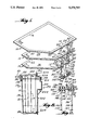
- FIG. 7 is front view of the housing of the invention.
- FIG. 8 is a sectional view taken along line 8--8 of FIG. 7;
- FIG. 9 is a sectional view taken along line 9--9 of FIG. 7;
- FIG. 10 is a back view of a receptacle according to the invention.
- FIG. 11 is a bottom view of the receptacle shown in FIG. 10;
- FIG. 12 is a view showing the opposite side of the receptacle from that shown in FIG. 10;
- FIG. 13 is a sectional view taken along line 13--13 of FIG. 10;
- FIG. 14 is a sectional view on an enlarged scale taken along line 14--14 of FIG. 12.
- FIG. 1 three flexible bags indicated generally by reference numerals 10, 12 and 14 each of which has a shape similar to the internal shape of the housing hereinafter described, the outer configuration of the housing being shaped complementary to the shape of a cavity in an analytical instrument with which the cartridge is to be used.
- the bag 10 is formed of polyethylene and is heat sealed along the periphery thereof as indicated by line 16. This is a liquid waste bag and may be provided with a conventional one-way flapper valve therein in the form of a pair of layers of material at the top of the bag which are adapted to separate and allow liquid to enter the bag, but which will be pressed together by pressure of liquid within the bag to prevent the flow of liquid waste out of the bag.
- a pair of support portions 18 are formed integral with the bag and include a pair of holes 20 therethrough for supporting the bag within the housing as hereinafter explained.
- a flexible tube 22 also formed of polyethylene has a first end 24 which is heat sealed within the sealed edge of the bag and which opens into the upper end of the bag as indicated at 10'.
- the opposite end of tube 22 terminates in an open end 26 adapted to be connected to the connector means hereinafter described.
- the second bag 12 is formed of two layers of aluminum foil each of which is coated on both sides with a layer of polyethylene.
- the bag is sealed along the periphery thereof by heat sealing as indicated by line 30.
- the bag is further heat sealed along the portion 32 thereof from top to bottom of the bag to define a pair of separate sealed chambers therewithin as indicated by numerals 34 and 36.
- Bag 12 is provided with a pair of support portions 40 having holes 42 formed therethrough for supporting the bag in operative position.
- a flexible tube 50 formed of polyethylene is heat sealed within the sealed edge of bag 12 and opens into the lower part of chamber 34.
- the opposite end of tube 50 terminates in an open end 52 adapted to be connected to the connector means.
- a tube 56 formed of polyethylene is heat sealed within the sealed edge of bag 12 and opens into the lower part of chamber 36.
- the opposite end of tube 56 terminates in an open end 58 adapted to be connected to the connector means.
- a flexible tube 60 formed of polyethylene has a one end 61 heat sealed within the sealed edge of bag 12 and opening into the upper part of chamber 36 as indicated at 12'.
- the opposite end of tube 60 terminates in an open end 62 adapted to be connected to the connector means.
- the third bag 14 is also formed of two layers of aluminum foil each of which is coated on both sides with a layer of polyethylene.
- the bag is sealed along the periphery thereof by heat sealing as indicated by line 66.
- the bag is further heat sealed along the portion 68 thereof from top to bottom of the bag to define a pair of separate sealed chambers therewithin as indicated by numerals 70 and 72.
- Bag 14 is provided with a pair of support portions 74 having holes 76 formed therethrough for supporting the bag in operative position.
- a flexible tube 80 also formed of polyethylene is heat sealed within the sealed edge of bag 14 and opens into the lower part of chamber 70.
- the opposite end of tube 80 terminates in an open end 82 adapted to be connected to the connector means.
- a flexible tube 84 formed of polyethylene is heat sealed within the sealed edge of bag 14 and opens into the lower part of chamber 72.
- the opposite end of tube 84 terminates in an open end 86 adapted to be connected to the connector means.
- chambers 34, 70 and 72 are initially filled with liquid reagents.
- Chamber 36 is initially filled with a reference solution which is recycled between chamber 36 and the associated analytical instrument.
- Bag 10 is initially empty and is subsequently filled with waste liquid produced during the normal analyzing operations of the associated instrument.
- the reference solution disposed within chamber 36 should be electrically shielded, and the aluminum foil serves to provide the desired electrical shield.
- the aluminum foil surrounding the other chambers containing reagents serves to prevent evaporation of the reagents.
- the connector means is an integral molded piece of relatively rigid unbreakable plastic material such as polycarbonate.
- the connector means includes a main body portion 100 having a first plurality of tapered bosses 102, 104, 106, 108, 110 and 112 extending from one side thereof.
- a second plurality of tapered bosses 122, 124, 126, 128, 130 and 132 are aligned with the first bosses and extend from the opposite side of body portion 100.
- a passage 134 is provided through aligned bosses 106 and 126.
- a similar passage is provided through each pair of aligned bosses.
- boss 106 is provided with a peripheral sharp edge or barb 136 which is adapted to cooperate with the end of an associated flexible tube to hold the tube in place on the boss and to provide a liquid-tight seal therewith. All of the bosses are provided with similar barbs to form a liquid-tight seal when the tubes are forced onto the associated bosses.
- an elongated nose portion 140 has a rounded outer end 142 for facilitating insertion and removal of the connector means relative to a cooperating receptacle hereinafter described.
- the nose portion has a peripheral groove 144 formed therearound to indicate that the connector means is properly seated in a cooperating receptacle.
- a pair of support rods 146 and 148 extend from body portion 100 and serve to support the bags within the cartridge.
- the support rods have tapered outer ends 150 and 152 respectively to facilitate mounting of the bags on the support rods as the outer ends of the rods pass through the holes formed in the support portions of the bags.
- the support rods also include tapered retainer portions 154 and 156 respectively which extend from opposite sides of the rods. These retainer portions enable the bags to be easily slid into place on the rods, but prevent reverse movement of the bags so as to prevent the bags from moving off of the rods.
- end 82 of tube 80 is connected with boss 102 as indicated by the dotted lines.
- end 54 of tube 50 is connected to boss 104;
- end 86 of tube 84 is connected to boss 106;
- end 26 of tube 22 is connected to boss 108;
- end 58 of tube 56 is connected to boss 110; and
- end 62 of tube 60 is connected to boss 112.
- body 100 also includes tapered edges 158 and 160 along the top and bottom edges thereof As seen in FIG. 2, body 100 also has tapered edges 162 and 164 formed along the side edges thereof. These tapered edges cooperate with the housing described below.
- the housing is illustrated, the housing being formed of a suitable plastic such as polyvinylchloride which is somewhat flexible, but sufficiently rigid to retain its outer shape and protect the bags supported therewithin.
- the housing includes an integral first housing portion 170 and a cover portion 172 which is permanently attached to the body portion.
- Body portion 170 includes a rear wall 176 having an outwardly extending generally rectangular portion 178 having an elongated slot 180 formed therethrough.
- the interior configuration and dimensions of the portion 178 are such that the body portion 100 of the connector means is adapted to snap into place within portion 178 with the tapered edges 158, 160, 162 and 164 disposed adjacent the inner walls of portion 178.
- the connector means is held in place with the tapered bosses 122, 124, 126, 128, 130 and 132 as well as the nose portion 140 extend outwardly through slot 180 to cooperate with a receptacle described hereinafter.
- Housing portion 170 includes a top wall 184 and a bottom wall 186 which join with a pair of opposite side walls 188 and 190.
- a continuous peripheral flange 192 extends along the top wall, each side wall and the bottom wall.
- Lid 172 includes a continuous peripheral flange 200 formed around the periphery thereof and having an elevational configuration as seen in FIG. 7 which is identical to the configuration of flange 192 on housing portion 170.
- the front wall 202 of the lid portion has a deformed part 204 immediately inwardly of the flange 192 and extending completely around the front wall as seen in FIG. 7.
- This deformed part fits snugly within the open end of housing portion 170 so that the deformed part serves to guide the lid portion into position during assembly of the cartridge with the deformed part frictionally engaging the inner surfaces of walls 184, 186, 188 and 190 of the housing portion.
- the flanges 192 and 200 are permanently bonded to one another by ultrasonic welding so that the housing is permanently closed to prevent access to the bags within the housing and thereby preventing tampering with the bags.
- the wall 202 of the lid portion also includes an outwardly extending integral portion 210 which in turn has outwardly extending integral projections 212 each of which defines a recess therein for receiving the outer end of one of the support rods formed on the connector means as seen in FIG. 8. In this manner, the connector means is held in operative position so that it cannot move inwardly relative to the housing and so that the support rods are maintained in the desired position.
- Portion 210 also includes a handle portion thereon to facilitate grasping and moving the housing.
- the handle portion comprises an arcuate surface 220 on portion 210 and adapted to receive a person's thumb as well as a recessed surface 222 on portion 210 adapted to receive the rest of the fingers of a person's hand whereby the entire housing may be held in the hand.
- the bags 10, 12 and 14 in empty condition are shown in phantom lines in FIG. 8 to illustrate the manner in which the bags are supported in operative position on the support rods within the cartridge.
- the receptacle for use with the cartridge and adapted to connect the cartridge to an analytical instrument is illustrated.
- the receptacle comprises an integral body 230 of resilient material such as thermoplastic elastomer.
- the body has a front surface 232 including a first plurality of recesses 234 formed therein and a second pair of recesses 236, these recesses being provided simply for the purpose of saving material.
- a protrusion 240 extends from surface 232 and is adapted to fit in a corresponding groove formed in an analytical instrument to properly position the receptacle relative to the instrument.
- a cylindrical passage 242 is formed through body 230 and extends from front surface 232 to rear surface 244 of the body. Surface 244 joins with sloping surfaces 246 and 248 at the top and bottom of the rear side of the body. Passage 242 is adapted to receive the nose portion 126 of the connector means to guide the receptacle onto the connector means.
- a recess 250 is provided in rear surface 244. This recess enables one to see the groove in the nose portion to determine that the connector means and receptacle are properly seated relative to one another.
- the recess is adapted to receive a person's finger so that when it is desired to disengage the receptacle from the connector means, a finger may be moved into the recess to engage the nose portion of an associated connector means to force the connector means away from the receptacle.
- each passage includes a first end 262 which is tapered and has a pair of seals in the form of spaced annular shoulders 264 and 266 which are adapted to engage and form a liquid tight seal with the six tapered bosses 122-132 formed on the connector means.
- the nose portion 140 of the connector is inserted through passage 242 until the groove 144 on the nose portion is visible within the recess 250, and when in this position, the tapered bosses 122-132 will be received within passages 260 and the outer surfaces of the bosses will be in sealing engagement with the sealing shoulders 264 and 266.
- each of the six passages 260 is in communication with the upper end of a plurality of similar grooves 274 formed in surface 244 of the receptacle. Each of these grooves receives a tube 276 similar to the tubes previously described and which are connected to an associated analytical instrument.
- These tubes are in liquid communication with ends 270 of passages 260 by means of conventional elbow connectors 280 having end portions 282 and 284 which have barb portions 286 and 288 formed therearound respectively to hold the elbow connectors in position and provide a liquid tight seal with passage 260 and tubes 276.
- the receptacle When a cartridge according to the invention is to be operatively connected with an analytical instrument, the receptacle is operatively connected with tubing from the instrument as shown in FIG. 14.
- the connector means is moved into operative relationship with the receptacle by inserting the nose portion and tapered bosses of the connector means into the appropriate passages provided through the receptacle.
- the entire assembly can be inserted into a cavity formed in the instrument with a single push, thereby simplifying this process.
- the cartridge may also be readily removed from the receptacle and disposed of when the fluids are depleted.
Abstract
Description
Claims (13)
Priority Applications (1)
| Application Number | Priority Date | Filing Date | Title |
|---|---|---|---|
| US07/956,263 US5279797A (en) | 1992-10-05 | 1992-10-05 | Disposable liquid reagent cartridge and receptacle therefor |
Applications Claiming Priority (1)
| Application Number | Priority Date | Filing Date | Title |
|---|---|---|---|
| US07/956,263 US5279797A (en) | 1992-10-05 | 1992-10-05 | Disposable liquid reagent cartridge and receptacle therefor |
Publications (1)
| Publication Number | Publication Date |
|---|---|
| US5279797A true US5279797A (en) | 1994-01-18 |
Family
ID=25497999
Family Applications (1)
| Application Number | Title | Priority Date | Filing Date |
|---|---|---|---|
| US07/956,263 Expired - Fee Related US5279797A (en) | 1992-10-05 | 1992-10-05 | Disposable liquid reagent cartridge and receptacle therefor |
Country Status (1)
| Country | Link |
|---|---|
| US (1) | US5279797A (en) |
Cited By (22)
| Publication number | Priority date | Publication date | Assignee | Title |
|---|---|---|---|---|
| EP0697248A1 (en) * | 1994-08-18 | 1996-02-21 | ABX , Société Anonyme dite | Reagent distribution housing for automatic connection to an apparatus such as a blood analyser |
| WO1997044662A1 (en) * | 1996-05-20 | 1997-11-27 | Sendx Medical, Inc. | Integral fluid and waste container for blood analyzer |
| US5820825A (en) * | 1996-05-20 | 1998-10-13 | Sendx Medical, Inc. | Waste container for portable blood analyzer |
| US5888408A (en) * | 1994-12-08 | 1999-03-30 | Heraeus Instruments Gmbh & Co. Kg | Process for collecting and preparing stored blood, apparatus suitable for said process and use of the apparatus |
| US5913232A (en) * | 1996-05-20 | 1999-06-15 | Sendx Medical, Inc. | reference solution container for blood gas/electrolyte measuring system |
| US5980830A (en) * | 1996-05-20 | 1999-11-09 | Sendx Medical, Inc. | Portable modular blood analyzer with simplified fluid handling sequence |
| WO2001068031A1 (en) * | 2000-03-16 | 2001-09-20 | P.U. Med. Konsult | Method and apparatus for treatment of biological material |
| US6309890B1 (en) * | 1997-08-19 | 2001-10-30 | BIOMéRIEUX, INC. | Locking structure for securing a fluid transfer tube |
| US6426230B1 (en) | 1997-08-01 | 2002-07-30 | Qualigen, Inc. | Disposable diagnostic device and method |
| US6729369B2 (en) | 1998-07-31 | 2004-05-04 | Chata Biosystems, Inc. | Vessel for containing/transporting a fluent substance |
| US20090137029A1 (en) * | 2007-06-21 | 2009-05-28 | Gen-Probe Incorporated | Multi-Chambered Receptacles |
| US20090176314A1 (en) * | 2008-01-07 | 2009-07-09 | Roche Diagnostics Operations, Inc. | Reagent cartridge |
| WO2013174762A1 (en) * | 2012-05-22 | 2013-11-28 | C2 Diagnostics | Fluid connection device for biological analysis apparatuses, suitable fluidic component and biological analysis device equipped with same |
| US20150093834A1 (en) * | 2012-12-13 | 2015-04-02 | Roche Molecular Systems, Inc. | Supply module for an automated analyzer |
| US9075042B2 (en) | 2012-05-15 | 2015-07-07 | Wellstat Diagnostics, Llc | Diagnostic systems and cartridges |
| US9213043B2 (en) | 2012-05-15 | 2015-12-15 | Wellstat Diagnostics, Llc | Clinical diagnostic system including instrument and cartridge |
| US20170056880A1 (en) * | 2015-08-26 | 2017-03-02 | EMULATE, Inc. | Fluid connections using guide mechanisms |
| US9625465B2 (en) | 2012-05-15 | 2017-04-18 | Defined Diagnostics, Llc | Clinical diagnostic systems |
| AU2018204596B2 (en) * | 2005-12-21 | 2020-03-12 | Meso Scale Technologies, Llc | Assay Apparatuses, Methods and Reagents |
| CN110927398A (en) * | 2020-02-18 | 2020-03-27 | 南京德名声科技有限公司 | Integrated kit, matching device and using method thereof |
| WO2020172495A1 (en) * | 2019-02-22 | 2020-08-27 | Retela Leasing, Llc | Controlled generation of measurable signals and uses thereof |
| US11300571B2 (en) | 2005-12-21 | 2022-04-12 | Meso Scale Technologies, Llc. | Assay apparatuses, methods and reagents |
Citations (24)
| Publication number | Priority date | Publication date | Assignee | Title |
|---|---|---|---|---|
| US3718439A (en) * | 1970-06-12 | 1973-02-27 | Instrumentation Labor Inc | Analytical apparatus |
| US3963148A (en) * | 1974-01-10 | 1976-06-15 | Coulter Electronics, Inc. | Apparatus for drawing, measuring and discharging proportional amounts of fluid |
| US4116336A (en) * | 1975-05-30 | 1978-09-26 | Radiometer A/S | Package containing a reference liquid for blood gas equipment |
| US4178345A (en) * | 1978-02-08 | 1979-12-11 | Abbott Laboratories | Cuvette cartridge |
| US4195060A (en) * | 1978-02-08 | 1980-03-25 | Abbott Laboratories | Liquid reagent cartridge cuvette |
| US4328185A (en) * | 1980-06-26 | 1982-05-04 | Boehringer Mannheim Corporation | Automated chemical testing apparatus |
| US4390499A (en) * | 1981-08-13 | 1983-06-28 | International Business Machines Corporation | Chemical analysis system including a test package and rotor combination |
| US4548606A (en) * | 1983-09-29 | 1985-10-22 | Abbott Laboratories | Dual compartmented container with activating means |
| US4570827A (en) * | 1984-03-28 | 1986-02-18 | Essex Chemical Corp. | Liquid dispenser |
| US4588554A (en) * | 1982-02-25 | 1986-05-13 | Fluilogic Systems Oy | Reagent package |
| US4691845A (en) * | 1985-05-31 | 1987-09-08 | Minnesota Mining And Manufacturing Company | Dispensing container |
| US4693867A (en) * | 1984-03-05 | 1987-09-15 | Societe Prolabo (Societe Anonyme) | Mineralization apparatus for the individual, automatic, treatment of samples of products placed in recipients |
| US4796788A (en) * | 1987-08-26 | 1989-01-10 | Liqui-Box Corporation | Bag-in-box packaging and dispensing of substances which will not readily flow by gravity |
| US4869398A (en) * | 1986-11-25 | 1989-09-26 | Life Technologies, Inc. | Liquid container delivery and storage system |
| US4889692A (en) * | 1984-11-05 | 1989-12-26 | Holtzman Marc E | Disposable sample preparation container |
| US4970053A (en) * | 1986-07-11 | 1990-11-13 | Beckman Instruments, Inc. | Reagent cartridge |
| US5031797A (en) * | 1988-11-18 | 1991-07-16 | Beckman Instruments, Inc. | Reagent storage and delivery system |
| US5075082A (en) * | 1986-07-11 | 1991-12-24 | Beckman Instruments, Inc. | Reagent cartridge |
| US5104813A (en) * | 1989-04-13 | 1992-04-14 | Biotrack, Inc. | Dilution and mixing cartridge |
| US5115943A (en) * | 1988-09-30 | 1992-05-26 | Fabricated Metals, Inc. | Bulk material container with a flexible liner |
| US5132026A (en) * | 1991-03-21 | 1992-07-21 | Alpha Therapeutic Corporation | Blood plasma collection system |
| US5135497A (en) * | 1991-07-08 | 1992-08-04 | Baxter International Inc. | Large volume pressurized fluid dispenser |
| US5154888A (en) * | 1990-10-25 | 1992-10-13 | Eastman Kodak Company | Automatic sealing closure means for closing off a passage in a flexible cuvette |
| US5163587A (en) * | 1989-12-11 | 1992-11-17 | Rehrig-Pacific Co. | Syrup delivery system |
-
1992
- 1992-10-05 US US07/956,263 patent/US5279797A/en not_active Expired - Fee Related
Patent Citations (24)
| Publication number | Priority date | Publication date | Assignee | Title |
|---|---|---|---|---|
| US3718439A (en) * | 1970-06-12 | 1973-02-27 | Instrumentation Labor Inc | Analytical apparatus |
| US3963148A (en) * | 1974-01-10 | 1976-06-15 | Coulter Electronics, Inc. | Apparatus for drawing, measuring and discharging proportional amounts of fluid |
| US4116336A (en) * | 1975-05-30 | 1978-09-26 | Radiometer A/S | Package containing a reference liquid for blood gas equipment |
| US4195060A (en) * | 1978-02-08 | 1980-03-25 | Abbott Laboratories | Liquid reagent cartridge cuvette |
| US4178345A (en) * | 1978-02-08 | 1979-12-11 | Abbott Laboratories | Cuvette cartridge |
| US4328185A (en) * | 1980-06-26 | 1982-05-04 | Boehringer Mannheim Corporation | Automated chemical testing apparatus |
| US4390499A (en) * | 1981-08-13 | 1983-06-28 | International Business Machines Corporation | Chemical analysis system including a test package and rotor combination |
| US4588554A (en) * | 1982-02-25 | 1986-05-13 | Fluilogic Systems Oy | Reagent package |
| US4548606A (en) * | 1983-09-29 | 1985-10-22 | Abbott Laboratories | Dual compartmented container with activating means |
| US4693867A (en) * | 1984-03-05 | 1987-09-15 | Societe Prolabo (Societe Anonyme) | Mineralization apparatus for the individual, automatic, treatment of samples of products placed in recipients |
| US4570827A (en) * | 1984-03-28 | 1986-02-18 | Essex Chemical Corp. | Liquid dispenser |
| US4889692A (en) * | 1984-11-05 | 1989-12-26 | Holtzman Marc E | Disposable sample preparation container |
| US4691845A (en) * | 1985-05-31 | 1987-09-08 | Minnesota Mining And Manufacturing Company | Dispensing container |
| US5075082A (en) * | 1986-07-11 | 1991-12-24 | Beckman Instruments, Inc. | Reagent cartridge |
| US4970053A (en) * | 1986-07-11 | 1990-11-13 | Beckman Instruments, Inc. | Reagent cartridge |
| US4869398A (en) * | 1986-11-25 | 1989-09-26 | Life Technologies, Inc. | Liquid container delivery and storage system |
| US4796788A (en) * | 1987-08-26 | 1989-01-10 | Liqui-Box Corporation | Bag-in-box packaging and dispensing of substances which will not readily flow by gravity |
| US5115943A (en) * | 1988-09-30 | 1992-05-26 | Fabricated Metals, Inc. | Bulk material container with a flexible liner |
| US5031797A (en) * | 1988-11-18 | 1991-07-16 | Beckman Instruments, Inc. | Reagent storage and delivery system |
| US5104813A (en) * | 1989-04-13 | 1992-04-14 | Biotrack, Inc. | Dilution and mixing cartridge |
| US5163587A (en) * | 1989-12-11 | 1992-11-17 | Rehrig-Pacific Co. | Syrup delivery system |
| US5154888A (en) * | 1990-10-25 | 1992-10-13 | Eastman Kodak Company | Automatic sealing closure means for closing off a passage in a flexible cuvette |
| US5132026A (en) * | 1991-03-21 | 1992-07-21 | Alpha Therapeutic Corporation | Blood plasma collection system |
| US5135497A (en) * | 1991-07-08 | 1992-08-04 | Baxter International Inc. | Large volume pressurized fluid dispenser |
Cited By (55)
| Publication number | Priority date | Publication date | Assignee | Title |
|---|---|---|---|---|
| FR2723735A1 (en) * | 1994-08-18 | 1996-02-23 | Abx Sa | AUTOMATIC CONNECTION HOUSING FOR DISPENSING REAGENTS IN AN APPARATUS, IN PARTICULAR A HEMATOLOGICAL ANALYZER. |
| US5665315A (en) * | 1994-08-18 | 1997-09-09 | Abx Sa | Automatic connection box for distributing reagents in a haematological analyzer |
| EP0697248A1 (en) * | 1994-08-18 | 1996-02-21 | ABX , Société Anonyme dite | Reagent distribution housing for automatic connection to an apparatus such as a blood analyser |
| US5888408A (en) * | 1994-12-08 | 1999-03-30 | Heraeus Instruments Gmbh & Co. Kg | Process for collecting and preparing stored blood, apparatus suitable for said process and use of the apparatus |
| US5913232A (en) * | 1996-05-20 | 1999-06-15 | Sendx Medical, Inc. | reference solution container for blood gas/electrolyte measuring system |
| US5885533A (en) * | 1996-05-20 | 1999-03-23 | Sendx Medical, Inc. | Integral fluid and waste container for blood analyzer |
| US5820825A (en) * | 1996-05-20 | 1998-10-13 | Sendx Medical, Inc. | Waste container for portable blood analyzer |
| WO1997044662A1 (en) * | 1996-05-20 | 1997-11-27 | Sendx Medical, Inc. | Integral fluid and waste container for blood analyzer |
| US5980830A (en) * | 1996-05-20 | 1999-11-09 | Sendx Medical, Inc. | Portable modular blood analyzer with simplified fluid handling sequence |
| US6016683A (en) * | 1996-05-20 | 2000-01-25 | Sendx Medical, Inc. | Reference solution container for blood gas/electrolyte measuring system |
| US5882602A (en) * | 1996-05-20 | 1999-03-16 | Sendx Medical, Inc. | Integral fluid and waste container for blood analyzer |
| US6426230B1 (en) | 1997-08-01 | 2002-07-30 | Qualigen, Inc. | Disposable diagnostic device and method |
| US6309890B1 (en) * | 1997-08-19 | 2001-10-30 | BIOMéRIEUX, INC. | Locking structure for securing a fluid transfer tube |
| US6729369B2 (en) | 1998-07-31 | 2004-05-04 | Chata Biosystems, Inc. | Vessel for containing/transporting a fluent substance |
| WO2001068031A1 (en) * | 2000-03-16 | 2001-09-20 | P.U. Med. Konsult | Method and apparatus for treatment of biological material |
| US20030034312A1 (en) * | 2000-03-16 | 2003-02-20 | Peter Unger | Method and apparatus for treatment of biological material |
| US11892455B2 (en) | 2005-12-21 | 2024-02-06 | Meso Scale Technologies, Llc. | Assay apparatuses, methods and reagents |
| US11300571B2 (en) | 2005-12-21 | 2022-04-12 | Meso Scale Technologies, Llc. | Assay apparatuses, methods and reagents |
| AU2018204596B2 (en) * | 2005-12-21 | 2020-03-12 | Meso Scale Technologies, Llc | Assay Apparatuses, Methods and Reagents |
| US8491178B2 (en) | 2007-06-21 | 2013-07-23 | Gen-Probe Incorporated | Instruments and methods for mixing the contents of a detection chamber |
| US8765367B2 (en) | 2007-06-21 | 2014-07-01 | Gen-Probe Incorporated | Methods and instruments for processing a sample in a multi-chambered receptacle |
| US7780336B2 (en) | 2007-06-21 | 2010-08-24 | Gen-Probe Incorporated | Instruments and methods for mixing the contents of a detection chamber |
| US20110189661A1 (en) * | 2007-06-21 | 2011-08-04 | Gen-Probe Incorporated | Gravity-assisted mixing methods |
| US8048375B2 (en) | 2007-06-21 | 2011-11-01 | Gen-Probe Incorporated | Gravity-assisted mixing methods |
| US8052929B2 (en) | 2007-06-21 | 2011-11-08 | Gen-Probe Incorporated | Gravity-assisted mixing methods |
| US8480976B2 (en) | 2007-06-21 | 2013-07-09 | Gen-Probe Incorporated | Instruments and methods for mixing the contents of a detection chamber |
| US20090142745A1 (en) * | 2007-06-21 | 2009-06-04 | Gen-Probe Incorporated | Instruments and methods for exposing a receptacle to multiple thermal zones |
| US20090137029A1 (en) * | 2007-06-21 | 2009-05-28 | Gen-Probe Incorporated | Multi-Chambered Receptacles |
| US20090136913A1 (en) * | 2007-06-21 | 2009-05-28 | Gen-Probe Incorporated | Gravity-Assisted Mixing Methods |
| US8735055B2 (en) | 2007-06-21 | 2014-05-27 | Gen-Probe Incorporated | Methods of concentrating an analyte |
| US9744506B2 (en) | 2007-06-21 | 2017-08-29 | Gen-Probe Incorporated | Instruments for mixing the contents of a detection chamber |
| US8784745B2 (en) | 2007-06-21 | 2014-07-22 | Gen-Probe Incorporated | Methods for manipulating liquid substances in multi-chambered receptacles |
| US8828654B2 (en) | 2007-06-21 | 2014-09-09 | Gen-Probe Incorporated | Methods for manipulating liquid substances in multi-chambered receptacles |
| US11235295B2 (en) | 2007-06-21 | 2022-02-01 | Gen-Probe Incorporated | System and method of using multi-chambered receptacles |
| US11235294B2 (en) | 2007-06-21 | 2022-02-01 | Gen-Probe Incorporated | System and method of using multi-chambered receptacles |
| US10688458B2 (en) | 2007-06-21 | 2020-06-23 | Gen-Probe Incorporated | System and method of using multi-chambered receptacles |
| US7767447B2 (en) | 2007-06-21 | 2010-08-03 | Gen-Probe Incorporated | Instruments and methods for exposing a receptacle to multiple thermal zones |
| US10744469B2 (en) | 2007-06-21 | 2020-08-18 | Gen-Probe Incorporated | Multi-chambered receptacles |
| US9075033B2 (en) * | 2008-01-07 | 2015-07-07 | Roche Diagnostics Operations, Inc. | Reagent cartridge |
| US20090176314A1 (en) * | 2008-01-07 | 2009-07-09 | Roche Diagnostics Operations, Inc. | Reagent cartridge |
| US9075042B2 (en) | 2012-05-15 | 2015-07-07 | Wellstat Diagnostics, Llc | Diagnostic systems and cartridges |
| US9213043B2 (en) | 2012-05-15 | 2015-12-15 | Wellstat Diagnostics, Llc | Clinical diagnostic system including instrument and cartridge |
| US9081001B2 (en) | 2012-05-15 | 2015-07-14 | Wellstat Diagnostics, Llc | Diagnostic systems and instruments |
| US9625465B2 (en) | 2012-05-15 | 2017-04-18 | Defined Diagnostics, Llc | Clinical diagnostic systems |
| CN104380119B (en) * | 2012-05-22 | 2017-07-18 | 法国比特集团 | Equipment, suitable fluidic component and bioanalytical device equipped with the fluidic component are fluidly connected for bio-analysis instrument |
| US9731295B2 (en) | 2012-05-22 | 2017-08-15 | Bit Group France | Fluid connection device for biological analysis apparatuses, suitable fluidic component and biological analysis device equipped with same |
| CN104380119A (en) * | 2012-05-22 | 2015-02-25 | C2诊断公司 | Fluid connection device for biological analysis apparatuses, suitable fluidic component and biological analysis device equipped with same |
| FR2991055A1 (en) * | 2012-05-22 | 2013-11-29 | C2 Diagnostics | FLUIDIC CONNECTION DEVICE FOR BIOLOGICAL ANALYSIS APPARATUS, FLUIDIC COMPONENT ADAPTED AND BIOLOGICAL ANALYSIS APPARATUS THUS EQUIPPED THEREFOR; |
| WO2013174762A1 (en) * | 2012-05-22 | 2013-11-28 | C2 Diagnostics | Fluid connection device for biological analysis apparatuses, suitable fluidic component and biological analysis device equipped with same |
| US20150093834A1 (en) * | 2012-12-13 | 2015-04-02 | Roche Molecular Systems, Inc. | Supply module for an automated analyzer |
| US9733264B2 (en) * | 2013-12-13 | 2017-08-15 | Roche Molecular Systems, Inc. | Supply module for an automated analyzer |
| US20170056880A1 (en) * | 2015-08-26 | 2017-03-02 | EMULATE, Inc. | Fluid connections using guide mechanisms |
| WO2020172495A1 (en) * | 2019-02-22 | 2020-08-27 | Retela Leasing, Llc | Controlled generation of measurable signals and uses thereof |
| CN110927398A (en) * | 2020-02-18 | 2020-03-27 | 南京德名声科技有限公司 | Integrated kit, matching device and using method thereof |
| CN110927398B (en) * | 2020-02-18 | 2020-06-23 | 南京德名声科技有限公司 | Integrated kit, matching device and using method thereof |
Similar Documents
| Publication | Publication Date | Title |
|---|---|---|
| US5279797A (en) | Disposable liquid reagent cartridge and receptacle therefor | |
| EP0014805B1 (en) | System for dispensing fluid | |
| US4484351A (en) | Non-glass chemical container | |
| US6241122B1 (en) | Plug and amorphous container using the plug | |
| CN103394379B (en) | Make the containment system of the tissue stabilization of molecule and HD | |
| US4317525A (en) | Disposable body fluid collection device | |
| KR910011591A (en) | Pack for storing liquids with seals on the outer circumference | |
| EP0373667B1 (en) | Liquid collecting tube | |
| EP2526029B1 (en) | Test strip container with strip retainer and methods of manufacturing and utilization thereof | |
| EP0891867A2 (en) | Liquid containment and dispensing device with improved resistance to shock loads | |
| US3228444A (en) | Specimen container | |
| KR101883339B1 (en) | Tongs for sealing bag opening | |
| US3050216A (en) | Chambered milk can with thermo-plastic insertable cover plate | |
| US11370593B2 (en) | Segmented container volume apparatus | |
| RU2128138C1 (en) | Reusable packing and its stopper | |
| JP2000185768A (en) | Attaching and sealing structure of pump cylinder | |
| EP0281730A2 (en) | Improved aerosol structure | |
| JP3011075U (en) | Container | |
| JP2004226314A (en) | Reagent vessel | |
| JPH0692370A (en) | Liquid let-out container | |
| JPH0588621B2 (en) | ||
| JPH0653453U (en) | Bag-in-box for viscous liquids | |
| CN211214408U (en) | Medicine packing box | |
| US20220111994A1 (en) | Bottle storing two different types of liquid | |
| US20230257161A1 (en) | Segmented Shortwise Container Volume Apparatus |
Legal Events
| Date | Code | Title | Description |
|---|---|---|---|
| AS | Assignment |
Owner name: AVL SCIENTIFIC CORPORATION, GEORGIA Free format text: ASSIGNMENT OF ASSIGNORS INTEREST.;ASSIGNORS:BURNS, RICKEY D.;HEITZ, BERNHARD H.;MEINCKE, DREW F.;AND OTHERS;REEL/FRAME:006311/0228 Effective date: 19920930 |
|
| FPAY | Fee payment |
Year of fee payment: 4 |
|
| SULP | Surcharge for late payment | ||
| FPAY | Fee payment |
Year of fee payment: 8 |
|
| AS | Assignment |
Owner name: ROCHE DIAGNOSTICS OPERATIONS, INC., INDIANA Free format text: ASSIGNMENT OF ASSIGNORS INTEREST;ASSIGNOR:ROCHE DIAGNOSTICS CORPORATION;REEL/FRAME:015215/0061 Effective date: 20040101 Owner name: ROCHE DIAGNOSTICS OPERATIONS, INC.,INDIANA Free format text: ASSIGNMENT OF ASSIGNORS INTEREST;ASSIGNOR:ROCHE DIAGNOSTICS CORPORATION;REEL/FRAME:015215/0061 Effective date: 20040101 |
|
| REMI | Maintenance fee reminder mailed | ||
| LAPS | Lapse for failure to pay maintenance fees | ||
| LAPS | Lapse for failure to pay maintenance fees |
Free format text: PATENT EXPIRED FOR FAILURE TO PAY MAINTENANCE FEES (ORIGINAL EVENT CODE: EXP.); ENTITY STATUS OF PATENT OWNER: SMALL ENTITY |
|
| STCH | Information on status: patent discontinuation |
Free format text: PATENT EXPIRED DUE TO NONPAYMENT OF MAINTENANCE FEES UNDER 37 CFR 1.362 |
|
| FP | Lapsed due to failure to pay maintenance fee |
Effective date: 20060118 |