US5284483A - Acetabular cup inserting instrument - Google Patents
Acetabular cup inserting instrument Download PDFInfo
- Publication number
- US5284483A US5284483A US07/945,558 US94555892A US5284483A US 5284483 A US5284483 A US 5284483A US 94555892 A US94555892 A US 94555892A US 5284483 A US5284483 A US 5284483A
- Authority
- US
- United States
- Prior art keywords
- handle
- pawl
- housing
- control knob
- instrument
- Prior art date
- Legal status (The legal status is an assumption and is not a legal conclusion. Google has not performed a legal analysis and makes no representation as to the accuracy of the status listed.)
- Expired - Lifetime
Links
Images
Classifications
-
- A—HUMAN NECESSITIES
- A61—MEDICAL OR VETERINARY SCIENCE; HYGIENE
- A61F—FILTERS IMPLANTABLE INTO BLOOD VESSELS; PROSTHESES; DEVICES PROVIDING PATENCY TO, OR PREVENTING COLLAPSING OF, TUBULAR STRUCTURES OF THE BODY, e.g. STENTS; ORTHOPAEDIC, NURSING OR CONTRACEPTIVE DEVICES; FOMENTATION; TREATMENT OR PROTECTION OF EYES OR EARS; BANDAGES, DRESSINGS OR ABSORBENT PADS; FIRST-AID KITS
- A61F2/00—Filters implantable into blood vessels; Prostheses, i.e. artificial substitutes or replacements for parts of the body; Appliances for connecting them with the body; Devices providing patency to, or preventing collapsing of, tubular structures of the body, e.g. stents
- A61F2/02—Prostheses implantable into the body
- A61F2/30—Joints
- A61F2/46—Special tools or methods for implanting or extracting artificial joints, accessories, bone grafts or substitutes, or particular adaptations therefor
- A61F2/4603—Special tools or methods for implanting or extracting artificial joints, accessories, bone grafts or substitutes, or particular adaptations therefor for insertion or extraction of endoprosthetic joints or of accessories thereof
- A61F2/4609—Special tools or methods for implanting or extracting artificial joints, accessories, bone grafts or substitutes, or particular adaptations therefor for insertion or extraction of endoprosthetic joints or of accessories thereof of acetabular cups
-
- A—HUMAN NECESSITIES
- A61—MEDICAL OR VETERINARY SCIENCE; HYGIENE
- A61B—DIAGNOSIS; SURGERY; IDENTIFICATION
- A61B17/00—Surgical instruments, devices or methods, e.g. tourniquets
- A61B17/28—Surgical forceps
- A61B17/2812—Surgical forceps with a single pivotal connection
- A61B17/2841—Handles
-
- A—HUMAN NECESSITIES
- A61—MEDICAL OR VETERINARY SCIENCE; HYGIENE
- A61B—DIAGNOSIS; SURGERY; IDENTIFICATION
- A61B17/00—Surgical instruments, devices or methods, e.g. tourniquets
- A61B17/28—Surgical forceps
- A61B17/2812—Surgical forceps with a single pivotal connection
- A61B17/2833—Locking means
- A61B2017/2837—Locking means with a locking ratchet
-
- A—HUMAN NECESSITIES
- A61—MEDICAL OR VETERINARY SCIENCE; HYGIENE
- A61F—FILTERS IMPLANTABLE INTO BLOOD VESSELS; PROSTHESES; DEVICES PROVIDING PATENCY TO, OR PREVENTING COLLAPSING OF, TUBULAR STRUCTURES OF THE BODY, e.g. STENTS; ORTHOPAEDIC, NURSING OR CONTRACEPTIVE DEVICES; FOMENTATION; TREATMENT OR PROTECTION OF EYES OR EARS; BANDAGES, DRESSINGS OR ABSORBENT PADS; FIRST-AID KITS
- A61F2/00—Filters implantable into blood vessels; Prostheses, i.e. artificial substitutes or replacements for parts of the body; Appliances for connecting them with the body; Devices providing patency to, or preventing collapsing of, tubular structures of the body, e.g. stents
- A61F2/02—Prostheses implantable into the body
- A61F2/30—Joints
- A61F2/46—Special tools or methods for implanting or extracting artificial joints, accessories, bone grafts or substitutes, or particular adaptations therefor
- A61F2/4603—Special tools or methods for implanting or extracting artificial joints, accessories, bone grafts or substitutes, or particular adaptations therefor for insertion or extraction of endoprosthetic joints or of accessories thereof
-
- A—HUMAN NECESSITIES
- A61—MEDICAL OR VETERINARY SCIENCE; HYGIENE
- A61F—FILTERS IMPLANTABLE INTO BLOOD VESSELS; PROSTHESES; DEVICES PROVIDING PATENCY TO, OR PREVENTING COLLAPSING OF, TUBULAR STRUCTURES OF THE BODY, e.g. STENTS; ORTHOPAEDIC, NURSING OR CONTRACEPTIVE DEVICES; FOMENTATION; TREATMENT OR PROTECTION OF EYES OR EARS; BANDAGES, DRESSINGS OR ABSORBENT PADS; FIRST-AID KITS
- A61F2/00—Filters implantable into blood vessels; Prostheses, i.e. artificial substitutes or replacements for parts of the body; Appliances for connecting them with the body; Devices providing patency to, or preventing collapsing of, tubular structures of the body, e.g. stents
- A61F2/02—Prostheses implantable into the body
- A61F2/30—Joints
- A61F2/32—Joints for the hip
- A61F2/34—Acetabular cups
- A61F2002/3401—Acetabular cups with radial apertures, e.g. radial bores for receiving fixation screws
- A61F2002/3403—Polar aperture
-
- A—HUMAN NECESSITIES
- A61—MEDICAL OR VETERINARY SCIENCE; HYGIENE
- A61F—FILTERS IMPLANTABLE INTO BLOOD VESSELS; PROSTHESES; DEVICES PROVIDING PATENCY TO, OR PREVENTING COLLAPSING OF, TUBULAR STRUCTURES OF THE BODY, e.g. STENTS; ORTHOPAEDIC, NURSING OR CONTRACEPTIVE DEVICES; FOMENTATION; TREATMENT OR PROTECTION OF EYES OR EARS; BANDAGES, DRESSINGS OR ABSORBENT PADS; FIRST-AID KITS
- A61F2/00—Filters implantable into blood vessels; Prostheses, i.e. artificial substitutes or replacements for parts of the body; Appliances for connecting them with the body; Devices providing patency to, or preventing collapsing of, tubular structures of the body, e.g. stents
- A61F2/02—Prostheses implantable into the body
- A61F2/30—Joints
- A61F2/46—Special tools or methods for implanting or extracting artificial joints, accessories, bone grafts or substitutes, or particular adaptations therefor
- A61F2/4603—Special tools or methods for implanting or extracting artificial joints, accessories, bone grafts or substitutes, or particular adaptations therefor for insertion or extraction of endoprosthetic joints or of accessories thereof
- A61F2002/4629—Special tools or methods for implanting or extracting artificial joints, accessories, bone grafts or substitutes, or particular adaptations therefor for insertion or extraction of endoprosthetic joints or of accessories thereof connected to the endoprosthesis or implant via a threaded connection
Definitions
- the present invention relates to an acetabular cup inserting instrument which is used by a surgeon to insert and properly position an acetabular cup implant into its proper anatomical location.
- Both the main and second handles of the instrument include grooved, radial disks that intermesh and interlock when a locking sleeve forces the two handles together.
- the rotatable locking sleeve locks the second handle to the main handle.
- this instrument enables the second handle to be locked in selectable positions, when the locking sleeve is unlocked thereby disengaging the grooved disks, the second handle can fall unimpeded if it slips out of the surgeon's grasp. Therefore it is important that the surgeon maintain a good grasp on the second handle when in its released position. Free rotatability of the second handle can be prevented to a degree by backing off the locking sleeve to the point where the grooved disks are only partially disengaged. As the second handle is rotated, the teeth on the disks "jump" over each other in much the same fashion as gears that are only partially engaged. However, this jumping movement is very erratic and rough and does not provide the controlled movement that is desirable in order to accurately position the second handle when placing an acetabular cup during a hip replacement procedure.
- the present invention provides a simple, reliable ratcheting mechanism for moving and then locking the second handle into a desired position with respect to the first handle of an acetabular cup positioning instrument of the general type disclosed in U.S. Pat. No. 4,716,894.
- the acetabular cup inserting instrument of the present invention comprises a first elongated handle with a second elongated handle extending therefrom.
- the second handle is capable of ratcheting about the longitudinal axis of the first elongated handle.
- the second handle may be selectively locked in a desired position with respect to the first handle by means of a control knob on the ratcheting mechanism.
- the instrument aids in properly positioning an acetabular cup in the acetabulum.
- An advantage of the present invention is that the second handle rotates smoothly and in a controlled manner about the main handle when not locked thereto.
- the ratchet mechanism provides a positive engagement at each discrete radial position.
- increased accuracy in radially locating the second handle about the main handle is caused by a spring biased pawl carried by one handle engaging detents on the other handle.
- Another advantage of the present invention is that the second handle is prevented from swinging freely about the first handle. This increases control of the instrument during positioning of the cup.
- An additional advantage of the present invention is that it provides an instrument design which is more compact to increase the surgeon's view of the surgical field. This compact design also enables the instrument to be more lightweight.
- a further advantage of the present invention is that the second handle ratchets in both rotational directions. Rotation in both directions permits the surgeon to easily and quickly position the second handle where needed.
- Yet another advantage is that when the surgeon makes an adjustment to insert the cup, the surgeon may hold the second handle stationary while rotating the first handle.
- the invention in one form thereof, is an acetabular cup inserting instrument comprising a first elongated handle having a proximal end, a distal end and an intermediate section therebetween, the handle having means on the distal end thereof for attaching to an acetabular cup.
- a second handle extends from the intermediate section of the first handle and is rotatable about the first handle.
- a ratchet mechanism yieldably retains the second handle in a plurality of discrete angular positions as the second handle is rotated about the first handle.
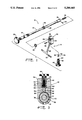
- FIG. 1 is an exploded view of the acetabular cup inserting instrument of the present invention
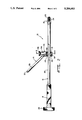
- FIG. 2 is a partial sectional side view of the assembled instrument of FIG. 1;
- FIG. 3 is a cross sectional view of the instrument taken along line 3--3 of FIG. 2.
- the acetabular cup inserting instrument 10 of the present invention includes a first elongated handle 12 and a second elongated handle 14 extending from first handle 12.
- Second handle 14 can be rotated 360° degrees about the longitudinal axis of first handle 12.
- Second handle 14 may be selectively rotated to a desired position with respect to first handle 12.
- first handle 12 may be rotated relative to second handle 14.
- First handle 12 includes a distal end 16, proximal end 18 and an interconnecting intermediate section 20 therebetween.
- Distal end 16 includes a means for engaging an acetabular cup (not shown) that securely holds and properly positions the cup.
- the means for engaging a cup such as a threaded stud 22, extends from distal end 16 of first handle 12.
- a locking pin 24 may be inserted into holes in first handle 12 and through threaded stud 22 to prevent rotation of stud 22 relative to first handle 12.
- Threaded stud 22 engages a corresponding threaded polar hole in an acetabular cup (not shown). It is understood that the instrument 10 of this invention may utilize any suitable acetabular cup engaging means for securing instrument 10 to an acetabular cup, such as an expanding collet, for example.
- First handle 12 is provided with enlarged head 26 which may be welded to proximal end 18.
- Enlarged head or knob 26 facilitates the driving of the acetabular cup.
- proximal end 18 and Knob 26 may include a knurled surface as shown in FIGS. 1 and 2 to assist in better gripping of instrument 10.
- Second handle 14 extends from first handle 12 toward the proximal end 18 at an angle of approximately 45° as shown in FIG. 2.
- Second handle 14 includes a main alignment arm extension 28 with a cross bar 30 to form a T-shaped handle.
- a sighting means (not shown), as is known in the art, may be attached to extension 28 to assist in cup placement.
- Second handle 14 further includes a ratchet mechanism 32 adapted to fit about first handle 12 for interconnecting second handle 14 to first handle 12.
- Ratchet mechanism 32 which is part of second handle 14, is rotatable 360° about first handle 12.
- Ratchet mechanism 32 of the present invention includes a housing 34 having a through-hole 36.
- First handle 12 interfits through hole 36 so that housing 34 may be preferably located on intermediate section 20.
- the diameter of distal portion of intermediate section 20 is greater than that of the proximal portion forming a shoulder 19.
- Attached to intermediate section 20 is a notched sleeve member 38 having notches or grooves 40.
- Notched member 38 is preferably welded to intermediate section 20, abutting shoulder 19.
- a retainer means such as retainer washer 42 in the form of a snap ring, for example, is secured against notched member 38 and to housing 34 to assure that ratchet mechanism 32 does not slide axially on first handle 12 after it has been attached.
- Retainer washer 42 operates by interfitting within a recess 44 in housing 34. This interfitting connection permits housing 34 to rotate about first handle 12 without moving axially.
- the ratcheting or clutch mechanism 32 is controlled by control knob 46 which is threaded for rotation through a threaded hole 48 in housing 34 (see FIG. 3).
- Control knob 46 includes a circumferential groove 50 that engages a locking cross pin 52.
- Cross pin 52 is inserted into housing 34 and prohibits removal of control knob 46 from threaded hole 48 yet allows a limited range of travel of knob 46.
- Threaded hole 48 joins a bore 54 that opens into hole 36.
- a slidable pawl or detent 56 having an engagement surface 58 and point 59 that mechanically and frictionally engages notched member 38 on first handle 12.
- a biased plunger 60 Located within control knob 46 is a biased plunger 60, that continuously biases pawl 56 into engagement with grooved portion 40.
- the limited range of travel of knob 46 enables the plunger 60 to always be in biased engagement with the pawl 56 to some degree.
- Plunger 60 is retained within control knob 46 by a plunger retainer 62 threaded into bore 63 of control knob 46.
- a biasing means such as a spring 66 is located behind plunger 60 to bias plunger 60 toward pawl 56.
- the biasing means allows second handle 14 to be located in any position and released without gravity causing second handle 14 to swing freely about first handle 12.
- the bias of spring 66 against plunger 60 which bias is translated to pawl 56, can be adjusted by rotating knob 46 into or out of housing 34.
- Notched member 38 includes a plurality of axially extending grooves or notches 40 and projections 41 that are engaged by pawl 56.
- the cross sectional angle of notches 40 is approximately 120°, although this angle may vary from 90° to 150° as desired.
- Pawl 56 preferably includes a point 59 with surfaces 58 that correspond to the mitered angle of notches 40. Additionally, notches 40 may be formed directly on first handle 12 thereby eliminating the need for notched member 38.
- the notches 40 are uniformly circumferentially spaced as shown in FIG. 3 to enable pawl 56, and therefore ratchet mechanism 32, to engage at any selected angular orientation about the longitudinal axis of first handle 12.
- Pawl 56 positively engages notches 40 on member 38 as second handle 14 is rotated about first handle 12 so that relative rotation between handles 12 and 14 can be accomplished smoothly and without any erratic movement. This enables the second handle to be yieldably retained at a desired angular position relative to first handle 12, yet easily moved when the rotation force applied thereto overcomes the mechanical and frictional engagement between pawl 56 and notched member 38.
- ratchet mechanism of the invention may be designed with other variations, such as to ratchet in only a single direction (not shown), instead of the preferred ratcheting mechanism shown.
- engagement surface 58 may include a roughened surface or coating to provide increased frictional engagement between pawl 56 and notched member 38. This high friction surface supplements the resistance and control function of pawl 56.
- ratchet or clutch mechanism 32 may employ a frictional or clutch pad locking mechanism (not shown) instead of the preferred ratcheting mechanism disclosed.
- an acetabular cup (not shown) is attached to distal end 16.
- stud 22 is threaded into a corresponding threaded hole in an acetabular cup.
- Ratchet or clutch mechanism 32 may be locked up by rotation of control knob 46. Inward rotation of control knob 46 into housing 34 causes the bottom surface 64 of control knob 46 to move into engagement with pawl 56. When this occurs, pawl 56 is locked from retracting out of notch 40, thereby preventing rotation between second handle 14 and first handle 12.
- the biasing means such as spring 66 may transmit a sufficient force to prevent pawl 56 from retracting and therefore lock second handle 14 in position.
- control knob 46 When control knob 46 is backed out of housing 34 and bottom surface 64 is not in engagement with pawl 56, spring biased plunger 60 maintains a yieldable bias against pawl 56.
- the engagement of pawl 56 with notched member 38 creates a ratchet feel as pawl 56 slides and "clicks" in an even manner over projections 41 when rotated about first handle 12. This ratchet action permits a surgeon to feel the location and movement of second handle 14 as it rotates relative to first handle 12. Once second handle 14 is properly aligned, control knob 46 then can be rotated into locking engagement with pawl 56. It is understood that the instrument of this invention may utilize any suitable control mechanism for regulating the engagement of the pawl.
- second handle 14 When second handle 14 is properly aligned and locked into position, the cup can then be properly positioned in the prepared acetabulum.
- second handle 14 via control knob 46, may be released and instrument 10 is then detached from the acetabular cup (not shown) by unthreading stud 22 from the cup.
- the present invention provides a second alignment handle 14 that is capable of ratcheting about the axis of first handle 12 in a controlled manner and then selectively locked in a desired position.
- the invention provides a simple and effective instrument which aids in the proper insertion of acetabular cup implants.
Abstract
Description
Claims (6)
Priority Applications (1)
| Application Number | Priority Date | Filing Date | Title |
|---|---|---|---|
| US07/945,558 US5284483A (en) | 1992-09-16 | 1992-09-16 | Acetabular cup inserting instrument |
Applications Claiming Priority (1)
| Application Number | Priority Date | Filing Date | Title |
|---|---|---|---|
| US07/945,558 US5284483A (en) | 1992-09-16 | 1992-09-16 | Acetabular cup inserting instrument |
Publications (1)
| Publication Number | Publication Date |
|---|---|
| US5284483A true US5284483A (en) | 1994-02-08 |
Family
ID=25483279
Family Applications (1)
| Application Number | Title | Priority Date | Filing Date |
|---|---|---|---|
| US07/945,558 Expired - Lifetime US5284483A (en) | 1992-09-16 | 1992-09-16 | Acetabular cup inserting instrument |
Country Status (1)
| Country | Link |
|---|---|
| US (1) | US5284483A (en) |
Cited By (55)
| Publication number | Priority date | Publication date | Assignee | Title |
|---|---|---|---|---|
| US5584837A (en) * | 1993-08-13 | 1996-12-17 | Petersen; Thomas D. | Acetabular cup inserter for orthopedic |
| US5683399A (en) * | 1995-12-01 | 1997-11-04 | Stelkast Incorporated | Acetabular cup insertion tool |
| US5904688A (en) * | 1997-12-30 | 1999-05-18 | Bristol-Myers Squibb Co. | Orthopaedic assembly including an acetabular cup and cup inserter |
| US5951564A (en) * | 1996-12-18 | 1999-09-14 | Bristol-Myers Squibb Company | Orthopaedic positioning apparatus |
| US6290726B1 (en) | 2000-01-30 | 2001-09-18 | Diamicron, Inc. | Prosthetic hip joint having sintered polycrystalline diamond compact articulation surfaces |
| US6398815B1 (en) | 2000-01-30 | 2002-06-04 | Diamicron, Inc. | Prosthetic joint having at least one superhard articulation surface |
| US6410877B1 (en) | 2000-01-30 | 2002-06-25 | Diamicron, Inc. | Methods for shaping and finishing prosthetic joint components including polycrystalline diamond compacts |
| US6425922B1 (en) | 2000-01-30 | 2002-07-30 | Diamicron, Inc. | Prosthetic hip joint having at least one sintered polycrystalline diamond compact articulation surface |
| US6488715B1 (en) | 2000-01-30 | 2002-12-03 | Diamicron, Inc. | Diamond-surfaced cup for use in a prosthetic joint |
| US6494918B1 (en) | 2000-01-30 | 2002-12-17 | Diamicron, Inc. | Component for a prosthetic joint having a diamond load bearing and articulation surface |
| US6596225B1 (en) | 2000-01-31 | 2003-07-22 | Diamicron, Inc. | Methods for manufacturing a diamond prosthetic joint component |
| US20030191533A1 (en) * | 2000-01-30 | 2003-10-09 | Diamicron, Inc. | Articulating diamond-surfaced spinal implants |
| US20030220698A1 (en) * | 2000-04-26 | 2003-11-27 | Dana Mears | Method and apparatus for performing a minimally invasive total hip arthroplasty |
| US6709463B1 (en) | 2000-01-30 | 2004-03-23 | Diamicron, Inc. | Prosthetic joint component having at least one solid polycrystalline diamond component |
| US20040073225A1 (en) * | 2002-10-15 | 2004-04-15 | Subba Rao Goli V. | Modular instrument for positioning acetabular prosthetic socket |
| US20040092944A1 (en) * | 2002-11-07 | 2004-05-13 | Penenberg Brad L. | Apparatus for, and method of, preparing for and inserting hip joint prosthesis using computer guidance |
| US20040153063A1 (en) * | 2003-02-04 | 2004-08-05 | Harris Brian R. | Acetabular impactor |
| US6793681B1 (en) | 1994-08-12 | 2004-09-21 | Diamicron, Inc. | Prosthetic hip joint having a polycrystalline diamond articulation surface and a plurality of substrate layers |
| US20040249389A1 (en) * | 2003-06-09 | 2004-12-09 | Kim Jun Hyun | Auxiliary apparatus for inserting a pin into a broken bone |
| US20050081867A1 (en) * | 2003-10-21 | 2005-04-21 | Murphy Stephen B. | Tissue preserving and minimally invasive hip replacement surgical procedure |
| US20050085823A1 (en) * | 2003-10-21 | 2005-04-21 | Murphy Stephen B. | Acetabular impactor |
| US20050187562A1 (en) * | 2004-02-03 | 2005-08-25 | Grimm James E. | Orthopaedic component inserter for use with a surgical navigation system |
| US20050203539A1 (en) * | 2004-03-08 | 2005-09-15 | Grimm James E. | Navigated stemmed orthopaedic implant inserter |
| US6997928B1 (en) | 2002-06-10 | 2006-02-14 | Wright Medical Technology, Inc. | Apparatus for and method of providing a hip replacement |
| US20070225725A1 (en) * | 2006-03-21 | 2007-09-27 | Zimmer Technology, Inc. | Modular acetabular component inserter |
| US20080109006A1 (en) * | 2006-10-17 | 2008-05-08 | Smith & Nephew, Inc. | Adjustable impactor handle |
| US20080167722A1 (en) * | 2007-01-10 | 2008-07-10 | Biomet Manufacturing Corp. | Knee Joint Prosthesis System and Method for Implantation |
| US20090149964A1 (en) * | 2007-10-10 | 2009-06-11 | Biomet Manufacturing Corp. | Knee joint prosthesis system and method for implantation |
| US20090299482A1 (en) * | 2007-01-10 | 2009-12-03 | Biomet Manufacturing Corp. | Knee Joint Prosthesis System and Method for Implantation |
| US20100131073A1 (en) * | 2008-11-24 | 2010-05-27 | Biomet Manufacturing Corp. | Multiple Bearing Acetabular Prosthesis |
| US7727282B2 (en) | 2006-03-17 | 2010-06-01 | Biomet Manufacturing Corp. | Method and apparatus for implanting a prosthesis |
| WO2010124164A1 (en) * | 2009-04-23 | 2010-10-28 | Ure Keith J | A device and method for achieving accurate positioning of acetabular cup during total hip replacement |
| US7833275B2 (en) | 2000-04-26 | 2010-11-16 | Zimmer Technology, Inc. | Method and apparatus for performing a minimally invasive total hip arthroplasty |
| US20110276100A1 (en) * | 2010-05-04 | 2011-11-10 | Depuy International Limited | Alignment guide |
| US20120109229A1 (en) * | 2009-07-10 | 2012-05-03 | Milux Holdind Sa | Hip joint instrument and method |
| US8187280B2 (en) | 2007-10-10 | 2012-05-29 | Biomet Manufacturing Corp. | Knee joint prosthesis system and method for implantation |
| US8308810B2 (en) | 2009-07-14 | 2012-11-13 | Biomet Manufacturing Corp. | Multiple bearing acetabular prosthesis |
| US8328873B2 (en) | 2007-01-10 | 2012-12-11 | Biomet Manufacturing Corp. | Knee joint prosthesis system and method for implantation |
| US20120330319A1 (en) * | 2010-05-04 | 2012-12-27 | Depuy International Limited | Alignment guide with spirit level |
| US20140336660A1 (en) * | 2011-05-03 | 2014-11-13 | Smith & Nephew, Inc. | Patient-matched guides for orthopedic implants |
| US20160128741A1 (en) * | 2010-01-15 | 2016-05-12 | Pioneer Surgical Technology, Inc. | Low Friction Rod Persuader |
| US9358130B2 (en) | 2012-03-29 | 2016-06-07 | DePuy Synthes Products, Inc. | Surgical instrument and method of positioning an acetabular prosthetic component |
| US9603722B2 (en) | 2009-05-05 | 2017-03-28 | Depuy International Limited | Alignment guide |
| CN108135586A (en) * | 2015-07-27 | 2018-06-08 | 黑普创新技术有限责任公司 | For being implanted into the ball of hip prosthesis and cup ram |
| US10390846B2 (en) | 2002-06-10 | 2019-08-27 | Microport Orthopedics Holdings Inc. | Apparatus for and method of providing a hip replacement |
| US10543097B2 (en) | 2012-09-20 | 2020-01-28 | Depuy Ireland Unlimited Company | Method and surgical instrument system with multiple lengths of broaches sharing a common geometry |
| US11484416B2 (en) * | 2019-06-04 | 2022-11-01 | DePuy Synthes Products, Inc. | Implant insertion tool for implanting an acetabular component and associated surgical method |
| US11517443B2 (en) | 2020-11-05 | 2022-12-06 | Warsaw Orthopedic, Inc. | Dual wedge expandable implant, system and method of use |
| US11517363B2 (en) | 2020-11-05 | 2022-12-06 | Warsaw Orthopedic, Inc. | Screw driver and complimentary screws |
| US11612499B2 (en) | 2021-06-24 | 2023-03-28 | Warsaw Orthopedic, Inc. | Expandable interbody implant |
| US11638653B2 (en) * | 2020-11-05 | 2023-05-02 | Warsaw Orthopedic, Inc. | Surgery instruments with a movable handle |
| US11806250B2 (en) | 2018-02-22 | 2023-11-07 | Warsaw Orthopedic, Inc. | Expandable spinal implant system and method of using same |
| US11833059B2 (en) | 2020-11-05 | 2023-12-05 | Warsaw Orthopedic, Inc. | Expandable inter-body device, expandable plate system, and associated methods |
| US11963881B2 (en) | 2020-11-05 | 2024-04-23 | Warsaw Orthopedic, Inc. | Expandable inter-body device, system, and method |
| US11969196B2 (en) | 2020-11-05 | 2024-04-30 | Warsaw Orthopedic, Inc. | Expandable inter-body device, system, and method |
Citations (10)
| Publication number | Priority date | Publication date | Assignee | Title |
|---|---|---|---|---|
| US4305394A (en) * | 1980-12-22 | 1981-12-15 | Bertuch Jr Charles J | Acetabular cup positioning instrument |
| US4475549A (en) * | 1982-01-18 | 1984-10-09 | Indong Oh | Acetabular cup positioner and method |
| US4528980A (en) * | 1983-10-19 | 1985-07-16 | Howmedica, Inc. | Acetabulum sizer and drill guide |
| US4632111A (en) * | 1985-03-21 | 1986-12-30 | Minnesota Mining And Manufacturing Company | Acetabular cup positioning apparatus |
| US4716894A (en) * | 1986-08-27 | 1988-01-05 | Zimmer, Inc. | Acetabular cup inserting instrument |
| US4911179A (en) * | 1987-05-28 | 1990-03-27 | Rolls-Royce Plc | Patient restraining device for use in physiotherapy |
| US4993410A (en) * | 1989-05-01 | 1991-02-19 | Kimsey Timothy P | Prosthetic removal device |
| US5030221A (en) * | 1989-12-13 | 1991-07-09 | Buechel Frederick F | Prosthesis holding system |
| US5037424A (en) * | 1989-12-21 | 1991-08-06 | Aboczsky Robert I | Instrument for orienting, inserting and impacting an acetabular cup prosthesis |
| US5116339A (en) * | 1990-07-11 | 1992-05-26 | Glock Steven R | Acetabular cup installation tool and method of installing an acetabular cup |
-
1992
- 1992-09-16 US US07/945,558 patent/US5284483A/en not_active Expired - Lifetime
Patent Citations (10)
| Publication number | Priority date | Publication date | Assignee | Title |
|---|---|---|---|---|
| US4305394A (en) * | 1980-12-22 | 1981-12-15 | Bertuch Jr Charles J | Acetabular cup positioning instrument |
| US4475549A (en) * | 1982-01-18 | 1984-10-09 | Indong Oh | Acetabular cup positioner and method |
| US4528980A (en) * | 1983-10-19 | 1985-07-16 | Howmedica, Inc. | Acetabulum sizer and drill guide |
| US4632111A (en) * | 1985-03-21 | 1986-12-30 | Minnesota Mining And Manufacturing Company | Acetabular cup positioning apparatus |
| US4716894A (en) * | 1986-08-27 | 1988-01-05 | Zimmer, Inc. | Acetabular cup inserting instrument |
| US4911179A (en) * | 1987-05-28 | 1990-03-27 | Rolls-Royce Plc | Patient restraining device for use in physiotherapy |
| US4993410A (en) * | 1989-05-01 | 1991-02-19 | Kimsey Timothy P | Prosthetic removal device |
| US5030221A (en) * | 1989-12-13 | 1991-07-09 | Buechel Frederick F | Prosthesis holding system |
| US5037424A (en) * | 1989-12-21 | 1991-08-06 | Aboczsky Robert I | Instrument for orienting, inserting and impacting an acetabular cup prosthesis |
| US5116339A (en) * | 1990-07-11 | 1992-05-26 | Glock Steven R | Acetabular cup installation tool and method of installing an acetabular cup |
Non-Patent Citations (4)
| Title |
|---|
| G. Cremascoli AN.C.A. Anatomic Ceramic Arthoplasty See p. 4 re item 8, The Driver Chuck (for Acetabular Cup) No date available. * |
| G. Cremascoli-AN.C.A. Anatomic Ceramic Arthoplasty-See p. 4 re item 8, The Driver Chuck (for Acetabular Cup)-No date available. |
| Osteonics Corp. Surgical Protocol Low Profile Threaded Omnifit Cup See Figs. 10 and 11 re Cup Driver with Ratchet Assembly 1986. * |
| Osteonics Corp.-"Surgical Protocol-Low Profile Threaded Omnifit Cup"-See Figs. 10 and 11 re Cup Driver with Ratchet Assembly-1986. |
Cited By (114)
| Publication number | Priority date | Publication date | Assignee | Title |
|---|---|---|---|---|
| US5584837A (en) * | 1993-08-13 | 1996-12-17 | Petersen; Thomas D. | Acetabular cup inserter for orthopedic |
| US6800095B1 (en) | 1994-08-12 | 2004-10-05 | Diamicron, Inc. | Diamond-surfaced femoral head for use in a prosthetic joint |
| US6793681B1 (en) | 1994-08-12 | 2004-09-21 | Diamicron, Inc. | Prosthetic hip joint having a polycrystalline diamond articulation surface and a plurality of substrate layers |
| US5683399A (en) * | 1995-12-01 | 1997-11-04 | Stelkast Incorporated | Acetabular cup insertion tool |
| US5951564A (en) * | 1996-12-18 | 1999-09-14 | Bristol-Myers Squibb Company | Orthopaedic positioning apparatus |
| US5904688A (en) * | 1997-12-30 | 1999-05-18 | Bristol-Myers Squibb Co. | Orthopaedic assembly including an acetabular cup and cup inserter |
| US6410877B1 (en) | 2000-01-30 | 2002-06-25 | Diamicron, Inc. | Methods for shaping and finishing prosthetic joint components including polycrystalline diamond compacts |
| US6709463B1 (en) | 2000-01-30 | 2004-03-23 | Diamicron, Inc. | Prosthetic joint component having at least one solid polycrystalline diamond component |
| US6425922B1 (en) | 2000-01-30 | 2002-07-30 | Diamicron, Inc. | Prosthetic hip joint having at least one sintered polycrystalline diamond compact articulation surface |
| US6488715B1 (en) | 2000-01-30 | 2002-12-03 | Diamicron, Inc. | Diamond-surfaced cup for use in a prosthetic joint |
| US6494918B1 (en) | 2000-01-30 | 2002-12-17 | Diamicron, Inc. | Component for a prosthetic joint having a diamond load bearing and articulation surface |
| US6497727B1 (en) | 2000-01-30 | 2002-12-24 | Diamicron, Inc. | Component for use in prosthetic hip, the component having a polycrystalline diamond articulation surface and a plurality of substrate layers |
| US6517583B1 (en) | 2000-01-30 | 2003-02-11 | Diamicron, Inc. | Prosthetic hip joint having a polycrystalline diamond compact articulation surface and a counter bearing surface |
| US6290726B1 (en) | 2000-01-30 | 2001-09-18 | Diamicron, Inc. | Prosthetic hip joint having sintered polycrystalline diamond compact articulation surfaces |
| US6610095B1 (en) | 2000-01-30 | 2003-08-26 | Diamicron, Inc. | Prosthetic joint having substrate surface topographical featurers and at least one diamond articulation surface |
| US20030191533A1 (en) * | 2000-01-30 | 2003-10-09 | Diamicron, Inc. | Articulating diamond-surfaced spinal implants |
| US6398815B1 (en) | 2000-01-30 | 2002-06-04 | Diamicron, Inc. | Prosthetic joint having at least one superhard articulation surface |
| US6402787B1 (en) | 2000-01-30 | 2002-06-11 | Bill J. Pope | Prosthetic hip joint having at least one sintered polycrystalline diamond compact articulation surface and substrate surface topographical features in said polycrystalline diamond compact |
| US6596225B1 (en) | 2000-01-31 | 2003-07-22 | Diamicron, Inc. | Methods for manufacturing a diamond prosthetic joint component |
| US6991656B2 (en) | 2000-04-26 | 2006-01-31 | Dana Mears | Method and apparatus for performing a minimally invasive total hip arthroplasty |
| US20030220698A1 (en) * | 2000-04-26 | 2003-11-27 | Dana Mears | Method and apparatus for performing a minimally invasive total hip arthroplasty |
| US7833275B2 (en) | 2000-04-26 | 2010-11-16 | Zimmer Technology, Inc. | Method and apparatus for performing a minimally invasive total hip arthroplasty |
| US20050177172A1 (en) * | 2000-04-26 | 2005-08-11 | Acker Dean M. | Method and apparatus for performing a minimally invasive total hip arthroplasty |
| US7780673B2 (en) | 2000-04-26 | 2010-08-24 | Zimmer Technology, Inc. | Method and apparatus for performing a minimally invasive total hip arthroplasty |
| US8740907B2 (en) | 2002-06-10 | 2014-06-03 | Microport Orthopedics Holdings Inc. | Apparatus for and method of providing a hip replacement |
| US10390846B2 (en) | 2002-06-10 | 2019-08-27 | Microport Orthopedics Holdings Inc. | Apparatus for and method of providing a hip replacement |
| US7833229B2 (en) | 2002-06-10 | 2010-11-16 | Wright Medical Technology Inc. | Apparatus for and method of providing a hip replacement |
| US6997928B1 (en) | 2002-06-10 | 2006-02-14 | Wright Medical Technology, Inc. | Apparatus for and method of providing a hip replacement |
| US20040073225A1 (en) * | 2002-10-15 | 2004-04-15 | Subba Rao Goli V. | Modular instrument for positioning acetabular prosthetic socket |
| US6743235B2 (en) * | 2002-10-15 | 2004-06-01 | Goli V. Subba Rao | Modular instrument for positioning acetabular prosthetic socket |
| US8034057B2 (en) * | 2002-11-07 | 2011-10-11 | Penenberg Brad L | Apparatus for, and method of, preparing for and inserting hip joint prosthesis using computer guidance |
| US20040092944A1 (en) * | 2002-11-07 | 2004-05-13 | Penenberg Brad L. | Apparatus for, and method of, preparing for and inserting hip joint prosthesis using computer guidance |
| US7247158B2 (en) | 2003-02-04 | 2007-07-24 | Wright Medical Technology, Inc. | Acetabular impactor |
| US20040153063A1 (en) * | 2003-02-04 | 2004-08-05 | Harris Brian R. | Acetabular impactor |
| US7186257B2 (en) * | 2003-06-09 | 2007-03-06 | Jun Hyun Kim | Auxiliary apparatus for inserting a pin into a broken bone |
| US20040249389A1 (en) * | 2003-06-09 | 2004-12-09 | Kim Jun Hyun | Auxiliary apparatus for inserting a pin into a broken bone |
| US20050081867A1 (en) * | 2003-10-21 | 2005-04-21 | Murphy Stephen B. | Tissue preserving and minimally invasive hip replacement surgical procedure |
| US7105028B2 (en) | 2003-10-21 | 2006-09-12 | Wright Medical Technology, Inc. | Tissue preserving and minimally invasive hip replacement surgical procedure |
| US7037310B2 (en) * | 2003-10-21 | 2006-05-02 | Wright Medical Technology Inc | Acetabular impactor |
| US20050085823A1 (en) * | 2003-10-21 | 2005-04-21 | Murphy Stephen B. | Acetabular impactor |
| US20050187562A1 (en) * | 2004-02-03 | 2005-08-25 | Grimm James E. | Orthopaedic component inserter for use with a surgical navigation system |
| US20050203539A1 (en) * | 2004-03-08 | 2005-09-15 | Grimm James E. | Navigated stemmed orthopaedic implant inserter |
| US7727282B2 (en) | 2006-03-17 | 2010-06-01 | Biomet Manufacturing Corp. | Method and apparatus for implanting a prosthesis |
| US20070225725A1 (en) * | 2006-03-21 | 2007-09-27 | Zimmer Technology, Inc. | Modular acetabular component inserter |
| US20080109006A1 (en) * | 2006-10-17 | 2008-05-08 | Smith & Nephew, Inc. | Adjustable impactor handle |
| US8425526B2 (en) * | 2006-10-17 | 2013-04-23 | Smith & Nephew, Inc. | Adjustable impactor |
| US8936648B2 (en) | 2007-01-10 | 2015-01-20 | Biomet Manufacturing, Llc | Knee joint prosthesis system and method for implantation |
| US20090299482A1 (en) * | 2007-01-10 | 2009-12-03 | Biomet Manufacturing Corp. | Knee Joint Prosthesis System and Method for Implantation |
| US20080167722A1 (en) * | 2007-01-10 | 2008-07-10 | Biomet Manufacturing Corp. | Knee Joint Prosthesis System and Method for Implantation |
| US8480751B2 (en) | 2007-01-10 | 2013-07-09 | Biomet Manufacturing, Llc | Knee joint prosthesis system and method for implantation |
| US8328873B2 (en) | 2007-01-10 | 2012-12-11 | Biomet Manufacturing Corp. | Knee joint prosthesis system and method for implantation |
| US8157869B2 (en) | 2007-01-10 | 2012-04-17 | Biomet Manufacturing Corp. | Knee joint prosthesis system and method for implantation |
| US8163028B2 (en) | 2007-01-10 | 2012-04-24 | Biomet Manufacturing Corp. | Knee joint prosthesis system and method for implantation |
| US8187280B2 (en) | 2007-10-10 | 2012-05-29 | Biomet Manufacturing Corp. | Knee joint prosthesis system and method for implantation |
| US9763793B2 (en) | 2007-10-10 | 2017-09-19 | Biomet Manufacturing, Llc | Knee joint prosthesis system and method for implantation |
| US20090149964A1 (en) * | 2007-10-10 | 2009-06-11 | Biomet Manufacturing Corp. | Knee joint prosthesis system and method for implantation |
| US8562616B2 (en) | 2007-10-10 | 2013-10-22 | Biomet Manufacturing, Llc | Knee joint prosthesis system and method for implantation |
| US10736747B2 (en) | 2007-10-10 | 2020-08-11 | Biomet Manufacturing, Llc | Knee joint prosthesis system and method for implantation |
| US8123815B2 (en) | 2008-11-24 | 2012-02-28 | Biomet Manufacturing Corp. | Multiple bearing acetabular prosthesis |
| US20100131073A1 (en) * | 2008-11-24 | 2010-05-27 | Biomet Manufacturing Corp. | Multiple Bearing Acetabular Prosthesis |
| US9445903B2 (en) | 2008-11-24 | 2016-09-20 | Biomet Manufacturing, Llc | Multi-bearing acetabular prosthesis |
| WO2010124164A1 (en) * | 2009-04-23 | 2010-10-28 | Ure Keith J | A device and method for achieving accurate positioning of acetabular cup during total hip replacement |
| US9603722B2 (en) | 2009-05-05 | 2017-03-28 | Depuy International Limited | Alignment guide |
| US20120109229A1 (en) * | 2009-07-10 | 2012-05-03 | Milux Holdind Sa | Hip joint instrument and method |
| US9241720B2 (en) * | 2009-07-10 | 2016-01-26 | Peter Forsell | Hip joint instrument and method |
| US8308810B2 (en) | 2009-07-14 | 2012-11-13 | Biomet Manufacturing Corp. | Multiple bearing acetabular prosthesis |
| US9445904B2 (en) | 2009-07-14 | 2016-09-20 | Biomet Manufacturing, Llc | Multiple bearing acetabular prosthesis |
| US20160128741A1 (en) * | 2010-01-15 | 2016-05-12 | Pioneer Surgical Technology, Inc. | Low Friction Rod Persuader |
| US10682167B2 (en) | 2010-01-15 | 2020-06-16 | Pioneer Surgical Technology, Inc. | Low friction rod persuader |
| US10070901B2 (en) * | 2010-01-15 | 2018-09-11 | Pioneer Surgical Technology, Inc. | Low friction rod persuader |
| US9693879B2 (en) * | 2010-05-04 | 2017-07-04 | Depuy International Limited | Alignment guide with spirit level |
| US20120330319A1 (en) * | 2010-05-04 | 2012-12-27 | Depuy International Limited | Alignment guide with spirit level |
| US20110276053A1 (en) * | 2010-05-04 | 2011-11-10 | Depuy International Limited | Method of using an alignment guide |
| US20140378984A1 (en) * | 2010-05-04 | 2014-12-25 | Depuy International Limited | Alignment guide with spirit level |
| US20160158027A1 (en) * | 2010-05-04 | 2016-06-09 | Depuy International Limited | Alignment guide |
| CN102869323B (en) * | 2010-05-04 | 2016-02-10 | 德普伊国际有限公司 | Calibration conductor |
| US20110276100A1 (en) * | 2010-05-04 | 2011-11-10 | Depuy International Limited | Alignment guide |
| CN102869323A (en) * | 2010-05-04 | 2013-01-09 | 德普伊国际有限公司 | Alignment guide |
| AU2011249990B2 (en) * | 2010-05-04 | 2015-05-28 | Depuy International Limited | Alignment guide |
| US9295566B2 (en) * | 2010-05-04 | 2016-03-29 | Depuy International Limited | Alignment guide |
| US9095448B2 (en) * | 2010-05-04 | 2015-08-04 | Depuy International Limited | Method of using an alignment guide |
| US20140336660A1 (en) * | 2011-05-03 | 2014-11-13 | Smith & Nephew, Inc. | Patient-matched guides for orthopedic implants |
| US9439781B2 (en) * | 2011-05-03 | 2016-09-13 | Smith & Nephew, Inc. | Patient-matched guides for orthopedic implants |
| US10285826B2 (en) | 2012-03-29 | 2019-05-14 | DePuy Synthes Products, Inc. | Surgical instrument and method of positioning an acetabular prosthetic component |
| US9358130B2 (en) | 2012-03-29 | 2016-06-07 | DePuy Synthes Products, Inc. | Surgical instrument and method of positioning an acetabular prosthetic component |
| US10583011B2 (en) | 2012-09-20 | 2020-03-10 | Depuy Ireland Unlimited Company | Method and system including sleeves and broaches for surgically preparing the patient's bone |
| US11648127B2 (en) | 2012-09-20 | 2023-05-16 | Depuy Ireland Unlimited Company | Method and system including sleeves and broaches for surgically preparing the patient's bone |
| US10543097B2 (en) | 2012-09-20 | 2020-01-28 | Depuy Ireland Unlimited Company | Method and surgical instrument system with multiple lengths of broaches sharing a common geometry |
| KR20180063878A (en) * | 2015-07-27 | 2018-06-12 | 힙 이노베이션 테크놀러지 엘엘씨 | Ball and cup impactor for implanting hip prostheses |
| AU2020260530B2 (en) * | 2015-07-27 | 2021-12-09 | Hip Innovation Technology, LLC | Ball and cup impactors for implanting a hip prosthesis |
| CN108135586A (en) * | 2015-07-27 | 2018-06-08 | 黑普创新技术有限责任公司 | For being implanted into the ball of hip prosthesis and cup ram |
| JP2018521798A (en) * | 2015-07-27 | 2018-08-09 | ヒップ イノベーション テクノロジー、エルエルシー | Ball and cup impactor for hip implants |
| US20180168821A1 (en) * | 2015-07-27 | 2018-06-21 | Hip Innovation Technology, Llc. | Ball and cup impactors for implanting a hip prosthesis |
| US10722382B2 (en) | 2015-07-27 | 2020-07-28 | Hip Innovation Technology, LLC | Ball and cup impactors for implanting a hip prosthesis |
| US10716683B2 (en) | 2015-07-27 | 2020-07-21 | Hip Innovation Technology Llc | Ball and cup impactors for implanting a hip prosthesis |
| AU2016298061B2 (en) * | 2015-07-27 | 2020-09-03 | Hip Innovation Technology, LLC | Ball and cup impactors for implanting a hip prosthesis |
| CN108135586B (en) * | 2015-07-27 | 2021-02-26 | 黑普创新技术有限责任公司 | Ball and cup impactor for implanting hip prosthesis |
| US10709580B2 (en) * | 2015-07-27 | 2020-07-14 | Hip Innovation Technology, LLC | Ball and cup impactors for implanting a hip prosthesis |
| AU2020260529B2 (en) * | 2015-07-27 | 2022-03-17 | Hip Innovation Technology, LLC | Ball and cup impactors for implanting a hip prosthesis |
| KR20230035450A (en) * | 2015-07-27 | 2023-03-13 | 힙 이노베이션 테크놀러지 엘엘씨 | Ball and cup impactors for implanting a hip prosthesis |
| KR20230035449A (en) * | 2015-07-27 | 2023-03-13 | 힙 이노베이션 테크놀러지 엘엘씨 | Ball and cup impactors for implanting a hip prosthesis |
| EP3328291A4 (en) * | 2015-07-27 | 2020-05-27 | HIP Innovation Technology, LLC | Ball and cup impactors for implanting a hip prosthesis |
| US11806250B2 (en) | 2018-02-22 | 2023-11-07 | Warsaw Orthopedic, Inc. | Expandable spinal implant system and method of using same |
| US11963886B2 (en) | 2019-06-04 | 2024-04-23 | DePuy Synthes Products, Inc. | Implant insertion tool for implanting an acetabular component and associated surgical method |
| US11484416B2 (en) * | 2019-06-04 | 2022-11-01 | DePuy Synthes Products, Inc. | Implant insertion tool for implanting an acetabular component and associated surgical method |
| US11517363B2 (en) | 2020-11-05 | 2022-12-06 | Warsaw Orthopedic, Inc. | Screw driver and complimentary screws |
| US11617658B2 (en) | 2020-11-05 | 2023-04-04 | Warsaw Orthopedic, Inc. | Expandable inter-body device, system and method |
| US11638653B2 (en) * | 2020-11-05 | 2023-05-02 | Warsaw Orthopedic, Inc. | Surgery instruments with a movable handle |
| US11564724B2 (en) | 2020-11-05 | 2023-01-31 | Warsaw Orthopedic, Inc. | Expandable inter-body device, system and method |
| US11833059B2 (en) | 2020-11-05 | 2023-12-05 | Warsaw Orthopedic, Inc. | Expandable inter-body device, expandable plate system, and associated methods |
| US11963881B2 (en) | 2020-11-05 | 2024-04-23 | Warsaw Orthopedic, Inc. | Expandable inter-body device, system, and method |
| US11517443B2 (en) | 2020-11-05 | 2022-12-06 | Warsaw Orthopedic, Inc. | Dual wedge expandable implant, system and method of use |
| US11969196B2 (en) | 2020-11-05 | 2024-04-30 | Warsaw Orthopedic, Inc. | Expandable inter-body device, system, and method |
| US11612499B2 (en) | 2021-06-24 | 2023-03-28 | Warsaw Orthopedic, Inc. | Expandable interbody implant |
Similar Documents
| Publication | Publication Date | Title |
|---|---|---|
| US5284483A (en) | Acetabular cup inserting instrument | |
| US4716894A (en) | Acetabular cup inserting instrument | |
| US5484440A (en) | Bone screw and screwdriver | |
| US6361488B1 (en) | Support apparatus for endoscopic surgery | |
| US11350951B2 (en) | Positioning device for securing an intramedullary nail in a long bone | |
| US5951564A (en) | Orthopaedic positioning apparatus | |
| US8308734B2 (en) | Implant insertion apparatus and method of use | |
| EP1651122B1 (en) | Plating system with multiple function drill guide | |
| US6050989A (en) | Angularly adjustable powered surgical handpiece | |
| US8236003B2 (en) | Prosthesis component holder attachable to an inserter handle | |
| CA2669644C (en) | Variable angle drill guide | |
| US7192432B2 (en) | Surgical drill guide | |
| EP0535973B1 (en) | An acetabular cup inserter | |
| US6080162A (en) | Modular orthopaedic clamping tool | |
| US5250051A (en) | Acetabular cup positioner with slaphammer mechanism for the removal of the sighting guide | |
| EP0556500A1 (en) | Surgical drill guide | |
| US5167476A (en) | Collet and tool assembly | |
| US20050216020A1 (en) | Assembly for use in orthopaedic surgery | |
| US20230087218A1 (en) | Retrograde drilling device | |
| EP1955667A1 (en) | Global nail screw retaining screwdriver | |
| CN105997190B (en) | Systems and methods for attaching a surgical instrument to a bone of a patient | |
| EP3624737B1 (en) | Implant assembly tools | |
| JP4071766B2 (en) | Intramedullary nail |
Legal Events
| Date | Code | Title | Description |
|---|---|---|---|
| AS | Assignment |
Owner name: ZIMMER, INC., INDIANA Free format text: ASSIGNMENT OF ASSIGNORS INTEREST.;ASSIGNORS:JOHNSON, ERIN M.;BAYLISS, LEROY C.;REEL/FRAME:006303/0279;SIGNING DATES FROM 19920914 TO 19920915 |
|
| STCF | Information on status: patent grant |
Free format text: PATENTED CASE |
|
| FPAY | Fee payment |
Year of fee payment: 4 |
|
| FPAY | Fee payment |
Year of fee payment: 8 |
|
| AS | Assignment |
Owner name: ZIMMER, INC., INDIANA Free format text: ASSIGNMENT OF ASSIGNORS INTEREST;ASSIGNOR:BRISTOL-MYERS SQUIBB COMPANY;REEL/FRAME:012729/0494 Effective date: 20020114 |
|
| AS | Assignment |
Owner name: ZIMMER TECHNOLOGY, INC., ILLINOIS Free format text: ASSIGNMENT OF ASSIGNORS INTEREST;ASSIGNOR:ZIMMER, INC.;REEL/FRAME:013862/0766 Effective date: 20020628 |
|
| FPAY | Fee payment |
Year of fee payment: 12 |