US5294068A - Dispenser for different width label rolls and method of using - Google Patents
Dispenser for different width label rolls and method of using Download PDFInfo
- Publication number
- US5294068A US5294068A US07/766,414 US76641491A US5294068A US 5294068 A US5294068 A US 5294068A US 76641491 A US76641491 A US 76641491A US 5294068 A US5294068 A US 5294068A
- Authority
- US
- United States
- Prior art keywords
- base member
- dispenser
- walls
- cover member
- latching
- Prior art date
- Legal status (The legal status is an assumption and is not a legal conclusion. Google has not performed a legal analysis and makes no representation as to the accuracy of the status listed.)
- Expired - Fee Related
Links
- 238000000034 method Methods 0.000 title claims description 3
- 238000005452 bending Methods 0.000 claims description 10
- 239000000463 material Substances 0.000 claims description 8
- 230000002093 peripheral effect Effects 0.000 claims description 4
- 230000001154 acute effect Effects 0.000 claims description 2
- 210000003811 finger Anatomy 0.000 description 18
- 230000003993 interaction Effects 0.000 description 2
- 239000003522 acrylic cement Substances 0.000 description 1
- 239000000853 adhesive Substances 0.000 description 1
- 230000001070 adhesive effect Effects 0.000 description 1
- 230000003247 decreasing effect Effects 0.000 description 1
- 238000006073 displacement reaction Methods 0.000 description 1
- 230000009977 dual effect Effects 0.000 description 1
- 230000000694 effects Effects 0.000 description 1
- 238000004519 manufacturing process Methods 0.000 description 1
- 230000001737 promoting effect Effects 0.000 description 1
- 210000003813 thumb Anatomy 0.000 description 1
- 230000000007 visual effect Effects 0.000 description 1
Images


Classifications
-
- B—PERFORMING OPERATIONS; TRANSPORTING
- B26—HAND CUTTING TOOLS; CUTTING; SEVERING
- B26F—PERFORATING; PUNCHING; CUTTING-OUT; STAMPING-OUT; SEVERING BY MEANS OTHER THAN CUTTING
- B26F3/00—Severing by means other than cutting; Apparatus therefor
- B26F3/02—Tearing
-
- B—PERFORMING OPERATIONS; TRANSPORTING
- B65—CONVEYING; PACKING; STORING; HANDLING THIN OR FILAMENTARY MATERIAL
- B65C—LABELLING OR TAGGING MACHINES, APPARATUS, OR PROCESSES
- B65C11/00—Manually-controlled or manually-operable label dispensers, e.g. modified for the application of labels to articles
-
- B—PERFORMING OPERATIONS; TRANSPORTING
- B65—CONVEYING; PACKING; STORING; HANDLING THIN OR FILAMENTARY MATERIAL
- B65H—HANDLING THIN OR FILAMENTARY MATERIAL, e.g. SHEETS, WEBS, CABLES
- B65H37/00—Article or web delivery apparatus incorporating devices for performing specified auxiliary operations
- B65H37/002—Web delivery apparatus, the web serving as support for articles, material or another web
- B65H37/005—Hand-held apparatus
-
- Y—GENERAL TAGGING OF NEW TECHNOLOGICAL DEVELOPMENTS; GENERAL TAGGING OF CROSS-SECTIONAL TECHNOLOGIES SPANNING OVER SEVERAL SECTIONS OF THE IPC; TECHNICAL SUBJECTS COVERED BY FORMER USPC CROSS-REFERENCE ART COLLECTIONS [XRACs] AND DIGESTS
- Y10—TECHNICAL SUBJECTS COVERED BY FORMER USPC
- Y10T—TECHNICAL SUBJECTS COVERED BY FORMER US CLASSIFICATION
- Y10T225/00—Severing by tearing or breaking
- Y10T225/20—Severing by manually forcing against fixed edge
- Y10T225/238—With housing for work supply
- Y10T225/244—Sectional telescoping housing
- Y10T225/245—Including removable cap or sleeve enclosure for spooled work supply
Definitions
- This invention relates to dispensers for labels carried a roll and, in particular, to dispensers of this type capable of handling label rolls of different widths.
- detectable labels are placed on articles to protect them against theft.
- the labels are formed in a line on a liner or backing which acts as a carrier for the labels.
- the liner is then wound onto a core to form a roll for transporting the labels and from which the labels can be dispensed for attachment to individual articles.
- a dispenser is used to house the roll and to detach individual labels from the roll. Since the label rolls may be of different widths depending upon whether a single line or multiple lines of labels are being carried, it is desirable that the dispensers used for the rolls be able to accommodate different width rolls.
- a label dispenser comprising a base member and a cover member which are provided, respectively, with a first bendable latching means and a second latching means which cooperate and are adapted to permit the cover member to be placed on the base member and to be latched to the base member at different latching positions corresponding to different distances or heights of the cover member from the base member.
- This allows the cover member and base member to together define interior regions of different heights which are able to receive label rolls of different widths.
- the first and second latching means are configured such that as the cover member is urged toward the base member the first latching means through bending and then retracting is able to latch to the second latching means at the first latching position and then through further bending and retracting is able to latch to the second latching means at the second latching position.
- Aperture means is additionally arranged in the cover member so that when the cover member is placed over the base member, the aperture means permits access to the first latching means for bending the first latching means. This bending is able to unlatch the first and second latching means from each other at the first and/or second latching positions so that the cover member and base member can be detached from each other.
- the base member includes a bottom wall which is bordered about its periphery by a side wall and whose interior region supports the first latching means.
- the first latching means has first and second longitudinally spaced latching members and is bendable so as to be able to displace these members.
- the cover member includes a top wall which includes the aperture means and which supports the second latching means.
- the second latching means has a third latching member.
- the second latching means is further arranged on the top wall of the cover member such that when the cover member is placed over the base member, the second latching means engages the first latching means and such that, as the cover member is urged toward the base member, the first latching means is first able to be bent so a to enable the third and first latching members to become latched and such that the first latching means is second able to be bent so as to enable the third and second latching members to become latched.
- the first latching means includes first and second spaced interior walls which have on their outer surfaces longitudinally spaced, laterally extending ribs which together define the first and second latching members.
- Each interior wall is bendable so as to be able to displace its ribs inwardly and the first latching means further includes first and second fingers extending from the first and second interior walls for applying inward forces to the walls.
- the aperture means of the top wall of the cover member includes first and second apertures situated so as to permit access to the first and second fingers of the first latching means of the base member when the cover member is placed over the base member.
- the third latching member of the cover member is formed from first and second latching flanges which extend downwardly from the top wall of the cover member and engage the outer surfaces of the respective first and second interior walls of the base member. Each latching flange is able to ride over and past the longitudinally spaced upper and lower ribs on the outer surface of the respective interior wall when the cover member is urged downwardly on the base member.
- the latching flanges When the latching flanges pass the upper ribs on the first and second interior walls, the latching flanges become latched to the interior walls by these upper ribs at a first height corresponding to the first latching position. At this position, the cover member and base member thus define a first interior region of first height. When the latching flanges pass the lower ribs, the latching flanges become latched to the first and second interior walls by these lower ribs at a second height corresponding to the second latching position. At this second position, the cover member and base member now define a second interior region of second height.
- the first and second latching flanges extend downwardly from outer circumferential areas of the first and second apertures and then inwardly, while inner circumferential areas of the apertures are provided with downwardly extending members which allow the cover to be gripped during withdrawal and which also provide stops for limiting the inward movement of the first and second fingers. Furthermore, in the disclosed embodiment, attention is focused on the apertures by locating them in a recessed area of the top wall of the cover member and by causing them to also decrease in dimension when proceeding inwardly.
- the upper and lower sets of ribs slope outwardly when proceeding downwardly so as to aid in the latching flanges moving downwardly past the ribs.
- the base member is provided with an additional sidewall portion which defines a handle for holding the dispenser.
- FIGS. 1A and 1B show representative label rolls for use with a dispenser in accordance with principles of the present invention
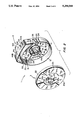
- FIG. 2 shows an isometric view of a dispenser in accordance with the principles of the present invention with the cover and base of the dispenser separated;
- FIG. 3 shows a front plan view of the base member of the dispenser of FIG. 1;
- FIG. 4 shows a cross sectional view of the base member of FIG. 3 taken through the section line A--A in FIG. 3;
- FIG. 5 shows a cross sectional view of the base member of FIG. 3 taken through the section line B--B in FIG. 3;
- FIG. 6 shows an enlarged view of an interior wall and attached finger of the base member of FIG. 3;
- FIGS. 7 and 8 show front and back plan views of the cover member of the dispenser of FIG. 2;
- FIG. 9 shows a top plan view of the cover member of the dispenser of FIG. 2.
- FIG. 10 shows a cross sectional view of the cover member of FIG. 8 taken through the section line C--C of FIG. 8.
- FIGS. 1A and 1B show typical label rolls 101 to be used with the dispenser of the present invention.
- Each label roll comprises an inner core member 102 around which is wound a liner or backing 103 carrying labels 104.
- the labels 104 are attached to the surface 103A of the liner by a releasable adhesive means such as an acrylic adhesive.
- the labels 104 typically may be detectable labels for use in an electronic article surveillance system. Labels of this type are disclosed for example in U.S. Pat. No. 4,660,025, assigned to the same assignee hereof.
- the roll in FIG. 1A carries a single line of labels, while the roll in FIG. 1B carries dual or multiple lines of labels.
- the width W2 of the FIG. 1B roll is thus greater than the width W1 of the FIG. 1A roll.
- FIG. 2 shows a dispenser 1 for dispensing labels from the label rolls of FIGS. 1A and 1B in accordance with the principles of the present invention.
- the dispenser 1 comprises a base member 2 and a cover member 3 which are adapted to be attached so as to provide interior regions of different height for accommodating the different widths W1 and W2 of the label rolls of FIGS. 1A and 1B.
- the base member 2 comprises a bottom wall 11 which is shown a being curved inwardly and as being circular.
- a side wall 12 extends upwardly from the periphery of the bottom wall 11 so that the base 2 is able to receive and house label rolls of maximum width at least equal to the larger width W2 of the rolls 101.
- First and second bendable or flexible, oppositely disposed interior walls 13 and 14 extend upwardly from a central region of the bottom wall 11.
- the interior walls 13 and 14 are bendable or pivotable about their lower ends affixed to the bottom wall 11 and these ends are further curved to follow opposite arcuate portions of a circular path.
- the upper portions of the inner walls 13 and 14 at their outer surfaces 13a, 14a are further provided with longitudinally displaced upper and lower laterally extending ribs 13b, 13c and 14b, 14c.
- the ribs on each wall are laterally offset from each other and, as will be further described below, cooperate with elements on the cover member to latch the base member 2 to the cover member 3 at their different heights from the bottom wall.
- Fingers 18 and 19 extend inwardly and then upwardly from the inner surfaces 13d and 14d of the interior walls 13 and 14. Inward forces applied to the upper ends of the fingers 18 and 19 thus bend the flexible walls 13 and 14 inward causing a corresponding inward displacement of the ribs 13b, 13c and 14b, 14c. This action is used to release the base member 2 from the cover member 3, as will also be described in more detail hereinbelow.
- the cover member 3 (see FIGS. 2 and 7-9) of the dispenser 1 includes a top wall 21 which is shown as curved or bent outwardly.
- the wall 21 is further shown as circular and carries about its periphery a downwardly extending rim or flange 22.
- the top wall 21 and rim 22 are dimensioned such that when the cover member 3 overlies the base member 2, the outer surface of the rim 22 is adjacent the inner surface of the side wall 12.
- the top surface 23 of the top wall 21 is provided with a recessed area 23a whose central region contains spaced apertures 24 and 25.
- the apertures 24 and 25 are of decreasing width when proceeding inwardly of the cover 3 and are further arranged such that they receive and permit access to the fingers 18 and 19, respectively, when the cover member 3 is situated on the base member 2.
- Members in the form of downwardly and then inwardly extending rigid flanges 26 and 27 extend from outer peripheral edges 24a and 25a of the apertures 24 and 25.
- the inner ends 26a, 27a of these flanges are situated to engage and grip the outer surfaces 13a and 14a of the interior walls 13 and 14 of the base member 2, when the cover member 3 is placed on the base member 2.
- the remaining peripheral portions 24b and 25b of the apertures 24 and 25 carry further downwardly extending rigid tabs 28 and 29.
- These tabs form surfaces for gripping the cover member 3 and for limiting the inward movement of the fingers 18 and 19 during unlatching or withdrawal of the cover member from the base member as will be discussed more fully below.
- the cover member 3 is situated over the base with the ends 26a and 27a of the flanges 26 and 27 engaging the outer surfaces 13a and 14a of the interior walls 13 and 14 of the base member.
- the cover member 3 is then urged downwardly with the ends 26a and 27a sliding along the wall surfaces. During this sliding movement, the fingers 18 and 19 of the base member are received in and become accessible through the apertures 24 and 25 in the cover member.
- the ends 26a, 27a of the flanges 26 and 27 will encounter the lower ribs 13c, 14c, which ribs are at an equal second height from the bottom wall 11 of base member 2.
- the ends 26a and 27a of the flanges 26 and 27 will cause the walls 13 and 14 to bend or flex inwardly toward each other thereby permitting the flange ends to ride over and past the lower ribs, which, like the upper ribs, are slanted outwardly, to create inward forces from the downward flange movement.
- the walls 13 and 14 again retract causing outward movement of the ribs over and above the flange ends 26a and 27a.
- a latching interaction between the ribs 13a and 14a and the ends 26a and 27a then occurs, since the horizontally extending, bottom walls of the ribs now block upward movement of the flange ends and their flanges 26 and 27.
- This position thus defines a second latching position for the cover member 3 and base member 2 at the second height of the lower ribs.
- the operator accesses the fingers 18 and 19 attached to the interior walls 13 and 14 by inserting two fingers (e.g., the thumb and index finger) of one hand into the apertures 24 and 25. The operator then urges the fingers 18 and 19 inwardly toward each other, while at the same time gripping the tabs 28 and 29 of the cover member with the two fingers.
- two fingers e.g., the thumb and index finger
- the tabs 28 and 29 not only act to provide gripping surfaces bu additionally interact with the fingers 18 and 19 to limit their inward movement. This, in turn, limits the inward flexing of the walls 13 and 14 so as to prevent the walls from being flexed about then lower ends beyond their breaking points.
- the base member 2 of the dispenser includes first and second sets of slots 31-33 and 34-36. These sets of slots are situated at opposite circumferential regions of the side wall 12 and permit labels to be dispensed from either side of the dispenser depending upon which set of slots is used.
- the slots 33 and 36 of the sets are provided with respective surfaces 33a and 36a having sharp or acute angled edges to facilitate stripping of the individual labels from the supporting liner.
- the roll end is first passed through either aperture 33 or 36 with the label side facing outward of the respective edge 33a or 36a. The end is then threaded through apertures 31-32 or 34-35. This results in the roll end being firmly held against the angled edge of the corresponding slot 33 or 36, thereby promoting detachment of the labels from the liner.
- Hollow bosses 37 and 38 are also provided adjacent the slot sets 31-33 and 34-36. Each boss provides a guide for guiding the roll end between the side all 12 and the respective boss and into the adjacent slot 33 or 36. Arrows 61-62 and 63-64 imprinted into the bottom wall 11 provide visual direction for threading the roll end relative to the bosses and slots.
- the bosses 37 and 38 can also be used to vertically mount the dispenser by inserting screws through the bosses.
- Radially extending supports or ribs 39 and 41 extend upwardly from the bottom wall 11 to support the body of the label roll in a level plane. These supports are aided by radical pins 42 which seat the core of the roll in the same plane.
- a side wall extension 12A provides a handle for the dispenser.
- the side wall extension 12A is slotted at 43A and 43B and 44A and 44B to define flexible flanges 43 and 44 having inner ledges 45 and 46. These slots, flanges and ledges can receive and support a strap for shoulder wear and carrying of the dispenser.
- the base member 2 is further provided with an L shaped clip 47.
- the latter clip extends downwardly below the bottom wall 11 and then inwardly and can be used to clip the dispenser 1 to the belt of an operator.
- the cover member 3 on its interior surface is also provided with arcuate ribs 51, 52 and radial ribs 53, 54. These ribs serve as stops and engage the label roll when the cover is latched to the base member 2 as above-described.
- the base member 2 and cover member 3 are each preferably formed as an integral unit. This can be accomplished by forming each as a molded element. Each element can furthermore comprise a plastic or some other moldable material. Advantageously, if each member is formed completely of a plastic material, each member is then recyclable.
- the latching flanges 26 and 27 of the cover member were disclosed as being substantially rigid members. However, these flanges also, could have been flexible, bendable or pivotable members adapted to provide the desired latching action.
Abstract
Description
Claims (30)
Priority Applications (1)
| Application Number | Priority Date | Filing Date | Title |
|---|---|---|---|
| US07/766,414 US5294068A (en) | 1991-09-26 | 1991-09-26 | Dispenser for different width label rolls and method of using |
Applications Claiming Priority (1)
| Application Number | Priority Date | Filing Date | Title |
|---|---|---|---|
| US07/766,414 US5294068A (en) | 1991-09-26 | 1991-09-26 | Dispenser for different width label rolls and method of using |
Publications (1)
| Publication Number | Publication Date |
|---|---|
| US5294068A true US5294068A (en) | 1994-03-15 |
Family
ID=25076358
Family Applications (1)
| Application Number | Title | Priority Date | Filing Date |
|---|---|---|---|
| US07/766,414 Expired - Fee Related US5294068A (en) | 1991-09-26 | 1991-09-26 | Dispenser for different width label rolls and method of using |
Country Status (1)
| Country | Link |
|---|---|
| US (1) | US5294068A (en) |
Cited By (34)
| Publication number | Priority date | Publication date | Assignee | Title |
|---|---|---|---|---|
| US5417319A (en) * | 1994-03-22 | 1995-05-23 | Hydrabaths, Inc. | Security container for display of audio and video media |
| USD380777S (en) * | 1996-01-02 | 1997-07-08 | Minnesota Mining And Manufacturing Company | Protector for a roll of tape |
| US5711493A (en) * | 1995-02-13 | 1998-01-27 | Eastman Kodak Company | Method and apparatus for storing and dispensing a roll of photographic web |
| US5779852A (en) * | 1996-06-11 | 1998-07-14 | Sensormatic Electronics Corporation | Handheld applicator |
| US6032799A (en) * | 1996-11-15 | 2000-03-07 | Sensormatic Electronics Corporation | Electronic article surveillance label cartridge and system |
| USD428922S (en) * | 1999-08-20 | 2000-08-01 | 3M Innovative Properties Company | Tape dispenser |
| US6364188B1 (en) | 1998-12-08 | 2002-04-02 | Wayne K. Dunshee | Tape dispenser |
| US6375780B1 (en) * | 1992-06-17 | 2002-04-23 | Micron Technology, Inc. | Method of manufacturing an enclosed transceiver |
| US6386416B1 (en) | 1998-04-21 | 2002-05-14 | 3M Innovative Properties Company | Tape dispenser |
| US6543511B2 (en) | 2000-12-01 | 2003-04-08 | Volker Niermann | Tape dispenser |
| US20040149798A1 (en) * | 2003-01-22 | 2004-08-05 | Xyron, Inc. | Crafting dispenser and dispenser system |
| US20050109790A1 (en) * | 2003-11-25 | 2005-05-26 | Nick Hsu | Window tabs storage case |
| US20050211743A1 (en) * | 2002-05-17 | 2005-09-29 | Martine Mandar | Tape detector device for dispenser |
| US20050242964A1 (en) * | 1992-08-12 | 2005-11-03 | Tuttle John R | Miniature radio frequency transceiver |
| US7017820B1 (en) | 2001-02-08 | 2006-03-28 | James Brunner | Machine and process for manufacturing a label with a security element |
| US20080035696A1 (en) * | 2006-08-08 | 2008-02-14 | Nichols Monica S | Sheet Product Package |
| US20080105723A1 (en) * | 2006-11-03 | 2008-05-08 | Chi-Tsai Chang | Dispensing device for adhesive tape |
| US20090078597A1 (en) * | 2007-09-20 | 2009-03-26 | Band-It-Idex, Inc. | Container for Storing and Dispensing a Plurality of Clamping Bands |
| US20090230164A1 (en) * | 2008-03-14 | 2009-09-17 | Louis Dale Freeman | Hands free operation adhesive tape dispenser |
| US20100200633A1 (en) * | 2009-02-12 | 2010-08-12 | 3M Innovative Properties Company | Tape dispenser |
| US7839285B2 (en) | 1997-08-20 | 2010-11-23 | Round Rock Resarch, LLC | Electronic communication devices, methods of forming electrical communication devices, and communications methods |
| US20120193389A1 (en) * | 2009-04-01 | 2012-08-02 | Chi-Tsai Chang | Adhesive tape dispenser |
| US20130284843A1 (en) * | 2012-04-30 | 2013-10-31 | Adc Telecommunications, Inc. | Cable storage spool with center feed |
| US20140131505A1 (en) * | 2012-11-12 | 2014-05-15 | Southwire Company | Wire and Cable Package |
| CN104684447A (en) * | 2012-08-29 | 2015-06-03 | Sca卫生用品公司 | Dispenser for canter feed roll |
| US9126802B2 (en) | 2012-04-30 | 2015-09-08 | Adc Telecommunications, Inc. | Payout spool with automatic cable disconnect/reconnect |
| US20150304756A1 (en) * | 2011-10-25 | 2015-10-22 | Tony Abfall | System and Method for the Protection and Storage of Small Electronic Components |
| US9500831B2 (en) | 2012-04-30 | 2016-11-22 | Commscope Technologies Llc | Cable payout cassette with single layer cable storage area |
| US20170029199A1 (en) * | 2015-07-28 | 2017-02-02 | Jean Hartman | Label Dispensing Assembly |
| USD790629S1 (en) * | 2013-03-15 | 2017-06-27 | Snotco, Llc | Masking tape |
| US9722407B2 (en) | 2012-04-30 | 2017-08-01 | Commscope Technologies Llc | Guided cable storage assembly with switchbacks |
| US20210179383A1 (en) * | 2016-11-01 | 2021-06-17 | Kitaru Innovations Inc. | Brake assembly for a tape dispenser |
| US11407607B2 (en) * | 2018-07-26 | 2022-08-09 | George Sarkissian | Dispenser |
| USD1014623S1 (en) * | 2020-07-30 | 2024-02-13 | Maria Liliana Alarcon | Reusable adhesive strip |
Citations (15)
| Publication number | Priority date | Publication date | Assignee | Title |
|---|---|---|---|---|
| US2533731A (en) * | 1949-06-03 | 1950-12-12 | Gomberg Jacob | Bobbin for knitting yarn and the like |
| US2678777A (en) * | 1953-03-17 | 1954-05-18 | Rexel Products Of Canada Ltd | Sensitive pressure tape dispenser |
| US2759545A (en) * | 1954-08-18 | 1956-08-21 | Frank E Rizza | Tape cutting attachment device for adhesive tape rolls |
| US2790609A (en) * | 1953-04-22 | 1957-04-30 | Johnson & Johnson | Adhesive tape dispenser |
| US2905408A (en) * | 1957-07-08 | 1959-09-22 | Western Electric Co | Adjustable and disassemblable reel |
| US3017132A (en) * | 1960-04-22 | 1962-01-16 | Eastman Kodak Co | Adjustable flanges for various width roll papers |
| US3147897A (en) * | 1961-05-02 | 1964-09-08 | Minnesota Mining & Mfg | Tape dispenser |
| US3447759A (en) * | 1967-05-19 | 1969-06-03 | Ben W Rau | Collapsible film reel |
| US4226381A (en) * | 1978-03-04 | 1980-10-07 | Dai-Ichi Seiko Co., Ltd. | Tape reel |
| US4433782A (en) * | 1981-10-20 | 1984-02-28 | Sigma Tool & Machine Limited | Magazine assembly for coil nails |
| US4570869A (en) * | 1983-01-04 | 1986-02-18 | Sanrio Company, Ltd. | Spool for ribbons, tapes, etc. |
| US4591110A (en) * | 1984-07-27 | 1986-05-27 | Mossberg Industries | Wire storing and dereeling apparatus |
| US4821918A (en) * | 1987-05-04 | 1989-04-18 | Net Associates, Inc. | Label dispenser and holder |
| US4884734A (en) * | 1987-05-08 | 1989-12-05 | Manco, Inc. | Tape dispenser |
| US5083717A (en) * | 1990-09-27 | 1992-01-28 | Minnesota Mining And Manufacturing Company | Refillable tape dispenser |
-
1991
- 1991-09-26 US US07/766,414 patent/US5294068A/en not_active Expired - Fee Related
Patent Citations (15)
| Publication number | Priority date | Publication date | Assignee | Title |
|---|---|---|---|---|
| US2533731A (en) * | 1949-06-03 | 1950-12-12 | Gomberg Jacob | Bobbin for knitting yarn and the like |
| US2678777A (en) * | 1953-03-17 | 1954-05-18 | Rexel Products Of Canada Ltd | Sensitive pressure tape dispenser |
| US2790609A (en) * | 1953-04-22 | 1957-04-30 | Johnson & Johnson | Adhesive tape dispenser |
| US2759545A (en) * | 1954-08-18 | 1956-08-21 | Frank E Rizza | Tape cutting attachment device for adhesive tape rolls |
| US2905408A (en) * | 1957-07-08 | 1959-09-22 | Western Electric Co | Adjustable and disassemblable reel |
| US3017132A (en) * | 1960-04-22 | 1962-01-16 | Eastman Kodak Co | Adjustable flanges for various width roll papers |
| US3147897A (en) * | 1961-05-02 | 1964-09-08 | Minnesota Mining & Mfg | Tape dispenser |
| US3447759A (en) * | 1967-05-19 | 1969-06-03 | Ben W Rau | Collapsible film reel |
| US4226381A (en) * | 1978-03-04 | 1980-10-07 | Dai-Ichi Seiko Co., Ltd. | Tape reel |
| US4433782A (en) * | 1981-10-20 | 1984-02-28 | Sigma Tool & Machine Limited | Magazine assembly for coil nails |
| US4570869A (en) * | 1983-01-04 | 1986-02-18 | Sanrio Company, Ltd. | Spool for ribbons, tapes, etc. |
| US4591110A (en) * | 1984-07-27 | 1986-05-27 | Mossberg Industries | Wire storing and dereeling apparatus |
| US4821918A (en) * | 1987-05-04 | 1989-04-18 | Net Associates, Inc. | Label dispenser and holder |
| US4884734A (en) * | 1987-05-08 | 1989-12-05 | Manco, Inc. | Tape dispenser |
| US5083717A (en) * | 1990-09-27 | 1992-01-28 | Minnesota Mining And Manufacturing Company | Refillable tape dispenser |
Cited By (51)
| Publication number | Priority date | Publication date | Assignee | Title |
|---|---|---|---|---|
| US6375780B1 (en) * | 1992-06-17 | 2002-04-23 | Micron Technology, Inc. | Method of manufacturing an enclosed transceiver |
| US8018340B2 (en) | 1992-08-12 | 2011-09-13 | Round Rock Research, Llc | System and method to track articles at a point of origin and at a point of destination using RFID |
| US7746230B2 (en) | 1992-08-12 | 2010-06-29 | Round Rock Research, Llc | Radio frequency identification device and method |
| US20070103316A1 (en) * | 1992-08-12 | 2007-05-10 | Tuttle John R | Radio frequency identification device and method |
| US20050242964A1 (en) * | 1992-08-12 | 2005-11-03 | Tuttle John R | Miniature radio frequency transceiver |
| US5417319A (en) * | 1994-03-22 | 1995-05-23 | Hydrabaths, Inc. | Security container for display of audio and video media |
| US5711493A (en) * | 1995-02-13 | 1998-01-27 | Eastman Kodak Company | Method and apparatus for storing and dispensing a roll of photographic web |
| USD380777S (en) * | 1996-01-02 | 1997-07-08 | Minnesota Mining And Manufacturing Company | Protector for a roll of tape |
| US5779852A (en) * | 1996-06-11 | 1998-07-14 | Sensormatic Electronics Corporation | Handheld applicator |
| US6032799A (en) * | 1996-11-15 | 2000-03-07 | Sensormatic Electronics Corporation | Electronic article surveillance label cartridge and system |
| US7948382B2 (en) | 1997-08-20 | 2011-05-24 | Round Rock Research, Llc | Electronic communication devices, methods of forming electrical communication devices, and communications methods |
| US7839285B2 (en) | 1997-08-20 | 2010-11-23 | Round Rock Resarch, LLC | Electronic communication devices, methods of forming electrical communication devices, and communications methods |
| US6386416B1 (en) | 1998-04-21 | 2002-05-14 | 3M Innovative Properties Company | Tape dispenser |
| US6364188B1 (en) | 1998-12-08 | 2002-04-02 | Wayne K. Dunshee | Tape dispenser |
| USD428922S (en) * | 1999-08-20 | 2000-08-01 | 3M Innovative Properties Company | Tape dispenser |
| US6543511B2 (en) | 2000-12-01 | 2003-04-08 | Volker Niermann | Tape dispenser |
| US7017820B1 (en) | 2001-02-08 | 2006-03-28 | James Brunner | Machine and process for manufacturing a label with a security element |
| US20050211743A1 (en) * | 2002-05-17 | 2005-09-29 | Martine Mandar | Tape detector device for dispenser |
| US20040149798A1 (en) * | 2003-01-22 | 2004-08-05 | Xyron, Inc. | Crafting dispenser and dispenser system |
| US20050109790A1 (en) * | 2003-11-25 | 2005-05-26 | Nick Hsu | Window tabs storage case |
| US20080035696A1 (en) * | 2006-08-08 | 2008-02-14 | Nichols Monica S | Sheet Product Package |
| US20080105723A1 (en) * | 2006-11-03 | 2008-05-08 | Chi-Tsai Chang | Dispensing device for adhesive tape |
| US7641087B2 (en) * | 2006-11-03 | 2010-01-05 | Chi-Tsai Chang | Dispensing device for adhesive tape |
| US20090078597A1 (en) * | 2007-09-20 | 2009-03-26 | Band-It-Idex, Inc. | Container for Storing and Dispensing a Plurality of Clamping Bands |
| US20090230164A1 (en) * | 2008-03-14 | 2009-09-17 | Louis Dale Freeman | Hands free operation adhesive tape dispenser |
| US20100200633A1 (en) * | 2009-02-12 | 2010-08-12 | 3M Innovative Properties Company | Tape dispenser |
| US20120193389A1 (en) * | 2009-04-01 | 2012-08-02 | Chi-Tsai Chang | Adhesive tape dispenser |
| US8602280B2 (en) * | 2009-04-01 | 2013-12-10 | Chi-Tsai Chang | Adhesive tape dispenser |
| US20150304756A1 (en) * | 2011-10-25 | 2015-10-22 | Tony Abfall | System and Method for the Protection and Storage of Small Electronic Components |
| US10567862B2 (en) | 2011-10-25 | 2020-02-18 | Digital Innovations Llc | System and method for the protection and storage of small electronic components |
| US9813797B2 (en) * | 2011-10-25 | 2017-11-07 | Digital Innovations Llc | System and method for the protection and storage of small electronic components |
| US9500831B2 (en) | 2012-04-30 | 2016-11-22 | Commscope Technologies Llc | Cable payout cassette with single layer cable storage area |
| US9722407B2 (en) | 2012-04-30 | 2017-08-01 | Commscope Technologies Llc | Guided cable storage assembly with switchbacks |
| US10625978B2 (en) | 2012-04-30 | 2020-04-21 | Commscope Technologies Llc | Cable storage spool with center feed |
| US20130284843A1 (en) * | 2012-04-30 | 2013-10-31 | Adc Telecommunications, Inc. | Cable storage spool with center feed |
| US9939600B2 (en) | 2012-04-30 | 2018-04-10 | Commscope Technologies Llc | Optical fiber disconnect/reconnect apparatus |
| US9126802B2 (en) | 2012-04-30 | 2015-09-08 | Adc Telecommunications, Inc. | Payout spool with automatic cable disconnect/reconnect |
| US9908742B2 (en) * | 2012-04-30 | 2018-03-06 | Commscope Technologies Llc | Cable storage spool with center feed |
| US9572461B2 (en) * | 2012-08-29 | 2017-02-21 | Sca Hygiene Products Ab | Dispenser for a center feed roll |
| CN104684447B (en) * | 2012-08-29 | 2017-03-15 | Sca卫生用品公司 | A kind of distributor for being centrally fed formula volume |
| CN104684447A (en) * | 2012-08-29 | 2015-06-03 | Sca卫生用品公司 | Dispenser for canter feed roll |
| US20150216377A1 (en) * | 2012-08-29 | 2015-08-06 | Sca Hygiene Products Ab | Dispenser for a center feed roll |
| US20140131505A1 (en) * | 2012-11-12 | 2014-05-15 | Southwire Company | Wire and Cable Package |
| US11117737B2 (en) * | 2012-11-12 | 2021-09-14 | Southwire Company, Llc | Wire and cable package |
| US11858719B2 (en) | 2012-11-12 | 2024-01-02 | Southwire Company, Llc | Wire and cable package |
| USD790629S1 (en) * | 2013-03-15 | 2017-06-27 | Snotco, Llc | Masking tape |
| US20170029199A1 (en) * | 2015-07-28 | 2017-02-02 | Jean Hartman | Label Dispensing Assembly |
| US20210179383A1 (en) * | 2016-11-01 | 2021-06-17 | Kitaru Innovations Inc. | Brake assembly for a tape dispenser |
| US11738964B2 (en) * | 2016-11-01 | 2023-08-29 | Kitaru Innovations Inc. | Brake assembly for a tape dispenser |
| US11407607B2 (en) * | 2018-07-26 | 2022-08-09 | George Sarkissian | Dispenser |
| USD1014623S1 (en) * | 2020-07-30 | 2024-02-13 | Maria Liliana Alarcon | Reusable adhesive strip |
Similar Documents
| Publication | Publication Date | Title |
|---|---|---|
| US5294068A (en) | Dispenser for different width label rolls and method of using | |
| US4340140A (en) | Package construction | |
| US5601349A (en) | Captive latch mechanism for use with an expansion card cage in a personal computer | |
| EP1404594A1 (en) | Horizontal cassette | |
| GB2240767A (en) | Adhesive note pad paper dispenser | |
| WO1992016964A2 (en) | Cushioned cover for wafer container | |
| US5806714A (en) | Label dispenser | |
| NL8400624A (en) | CARRIER FOR HOLDERS. | |
| US6182835B1 (en) | Device for mounting computer expansion slot covers | |
| KR20040035739A (en) | Modular carrier for semiconductor wafer disks and similar inventory | |
| GB2277188A (en) | Intermediate bulk container marking plate | |
| US20030080006A1 (en) | Fastening device for optical disc holder | |
| US2773727A (en) | Record holder | |
| US4735351A (en) | Dispenser for tape rolls | |
| EP0879193B1 (en) | Improved insertable tray | |
| KR100205528B1 (en) | Sheet for holding information recording carriers | |
| US7246702B2 (en) | Disk holder | |
| TW237559B (en) | Wafer carrier | |
| EP1338011B1 (en) | Improved disk holder | |
| JPS6233436A (en) | Wafer case for transport | |
| JP4695895B2 (en) | Tea bag latch and tea bag with double-sided tape | |
| US5927507A (en) | Replacement band display container | |
| AU2001294023A1 (en) | Improved disk holder | |
| JP4122089B2 (en) | IC tray clip | |
| EP1766627B1 (en) | Security apparatus |
Legal Events
| Date | Code | Title | Description |
|---|---|---|---|
| AS | Assignment |
Owner name: SENSORMATIC ELECTRONICS CORPORATION Free format text: ASSIGNMENT OF ASSIGNORS INTEREST.;ASSIGNORS:BARO, ANTHONY;WITZKY, HANS;REEL/FRAME:005859/0630 Effective date: 19910925 |
|
| CC | Certificate of correction | ||
| FEPP | Fee payment procedure |
Free format text: PAYOR NUMBER ASSIGNED (ORIGINAL EVENT CODE: ASPN); ENTITY STATUS OF PATENT OWNER: LARGE ENTITY |
|
| FPAY | Fee payment |
Year of fee payment: 4 |
|
| FPAY | Fee payment |
Year of fee payment: 8 |
|
| AS | Assignment |
Owner name: SENSORMATIC ELECTRONICS CORPORATION, FLORIDA Free format text: MERGER/CHANGE OF NAME;ASSIGNOR:SENSORMATIC ELECTRONICS CORPORATION;REEL/FRAME:012991/0641 Effective date: 20011113 |
|
| REMI | Maintenance fee reminder mailed | ||
| LAPS | Lapse for failure to pay maintenance fees | ||
| STCH | Information on status: patent discontinuation |
Free format text: PATENT EXPIRED DUE TO NONPAYMENT OF MAINTENANCE FEES UNDER 37 CFR 1.362 |
|
| FP | Lapsed due to failure to pay maintenance fee |
Effective date: 20060315 |