US5323075A - Hall effect sensors embedded within two-pole toothless stator assembly - Google Patents
Hall effect sensors embedded within two-pole toothless stator assembly Download PDFInfo
- Publication number
- US5323075A US5323075A US07/987,482 US98748292A US5323075A US 5323075 A US5323075 A US 5323075A US 98748292 A US98748292 A US 98748292A US 5323075 A US5323075 A US 5323075A
- Authority
- US
- United States
- Prior art keywords
- hall effect
- effect sensors
- boreseal
- stator
- support structure
- Prior art date
- Legal status (The legal status is an assumption and is not a legal conclusion. Google has not performed a legal analysis and makes no representation as to the accuracy of the status listed.)
- Expired - Lifetime
Links
Images

Classifications
-
- H—ELECTRICITY
- H02—GENERATION; CONVERSION OR DISTRIBUTION OF ELECTRIC POWER
- H02K—DYNAMO-ELECTRIC MACHINES
- H02K3/00—Details of windings
- H02K3/46—Fastening of windings on the stator or rotor structure
- H02K3/47—Air-gap windings, i.e. iron-free windings
-
- H—ELECTRICITY
- H02—GENERATION; CONVERSION OR DISTRIBUTION OF ELECTRIC POWER
- H02K—DYNAMO-ELECTRIC MACHINES
- H02K29/00—Motors or generators having non-mechanical commutating devices, e.g. discharge tubes or semiconductor devices
- H02K29/06—Motors or generators having non-mechanical commutating devices, e.g. discharge tubes or semiconductor devices with position sensing devices
- H02K29/08—Motors or generators having non-mechanical commutating devices, e.g. discharge tubes or semiconductor devices with position sensing devices using magnetic effect devices, e.g. Hall-plates, magneto-resistors
Definitions
- This invention relates in general to electrical machine systems and in particular to the location of Hall effect sensors relative to the stator assembly of a two-pole toothless permanent magnet brushless dc machine.
- a brushless dc motor system typically consists of a motor, a solid-state inverter, a controller and a rotor position sensing system.
- the motor includes a permanent magnet rotor and a stator whose polyphase power windings surround the rotor.
- the inverter Under command from the controller, the inverter energizes selected phase windings at the correct time and sequence to generate a stator mmf field that reacts with the rotor's flux field, causing the rotor to rotate.
- the rotor position sensing system generates with signals indicating the position of the rotor relative to the phase windings.
- the controller decodes these position signals into commutation commands which command the inverter to energize the phase windings at the correct time and sequence.
- the rotor position sensing system can include proximity probes and a back emf generator. During motor startup, the rotor position signals are generated by the proximity probes. Once the motor reaches roughly ten percent of maximum rated speed, however a switch is made to the back emf generator which generates the rotor position signals.
- the proximity probes sense the position of a cam that is mounted about one end of the motor's shaft, external to the motor.
- this design has the unwanted effect of increasing the axial length of the motor.
- the proximity probes must be adjusted for precise commutation.
- the rotor position sensing system can use Hall effect sensors.
- the Hall effect sensors are mounted underneath stator end turns where they work off rotor end leakage flux.
- the use of Hall effect sensors overcomes the problem of axial length. For small machines, however, the end leakage flux may not be sufficient for the Hall effect sensors to operate reliably.
- a system comprising a toothless machine, Hall effect sensors for indicating the position of the machine's rotor relative to its stator, and means for energizing power windings of the stator in response to position signals from the Hall effect sensors.
- the Hall effect sensors are embedded under the power windings of the stator and located in the main magnetic air gap between the rotor and stator. In this location, the Hall effect sensors are exposed to a greater number of flux lines than they would be if located under the stator end turns.
- This design is limited to machines whose current ratings are low and whose operating temperatures do not exceed the maximum allowable temperature rating of the Hall effect sensors.
- the Hall effect sensors When embedded in the stator's winding support structure, the Hall effect sensors do not have to be adjusted. Resulting is easy installation and packaging.
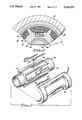
- FIG. 1 is a cross-sectional view of a two-pole toothless PM machine including a stator embodying the present invention
- FIG. 2 is a fragmentary cross-sectional view, taken along lines 2--2, of the machine shown in FIG. 1;
- FIG. 3 is an exploded view of a portion of the stator shown in FIG. 1.
- FIGS. 1 and 2 show a two pole toothless machine 10 including a main housing 12 having front and rear endbells 14 and 16 which carry bearings 18. Journalled in the bearings 18 are stub shafts 20 of a rotor 22. The shafts 20 rotate a cylindrical two pole permanent magnet 24 that is magnetized diametrically. Surrounding the magnet 24 is a retaining hoop 26. Construction of the rotor 22 is disclosed by Joseph Denk and Kenneth Wuertz in U.S. Pat. No. 4,667,123 (“TWO POLE PERMANENT MAGNET ROTOR CONSTRUCTION FOR TOOTHLESS STATOR ELECTRICAL MACHINE") and U.S. Pat. No. 4,741,094 (“TWO POLE PERMANENT MAGNET ROTOR CONSTRUCTION METHOD”), both of which patents are incorporated herein by reference.
- stator 28 Surrounding the rotor 22 is a stator 28 whose winding support structure 30 includes a cylindrical boreseal 32 and fins 34 extending radially outward from the boreseal 32. Power windings 36 are prewound in a conventional manner and installed on the support structure 30. For a two-pole, three phase machine having six stator slots, there are three sets of two coils. The portions of the power windings 36 extending axially beyond the support structure 30 are known as end turns.
- the support structure 30 is surrounded by an iron flux collector ring 38, which provides a flux return path for the flux from the rotor 22. Disposed between the support structure 30 and flux collector ring 38 is insulation 40.
- stator 28 Construction of the stator 28 is disclosed by Joseph Denk in U.S. Pat. No. 4,709,180 ("TOOTHLESS STATOR CONSTRUCTION FOR ELECTRICAL MACHINES") and U.S. Pat. No. 4,852,245 ("TOOTHLESS STATOR ELECTRICAL MACHINE CONSTRUCTION METHOD”), both of which patents are incorporated herein by reference.
- the patents disclosing stator and rotor construction for a two pole toothless machine are assigned to Allied Signal, Inc., the assignee of the present invention.
- the outer surface of the permanent magnet 24 and the inner surface of the flux collector ring 38 define a main magnetic air gap G. Flux is much greater in the main magnetic air gap G than at the end turns.
- Hall effect sensors 44 Embedded in the magnetic air gap G under the power windings 36 in the electromechanically correct position are Hall effect sensors 44.
- the Hall effect sensors 44 are spaced apart by 120 electrical and mechanical degrees.
- a second set of sensors is employed, shifted from the primary Hall effect sensors 44 by 60 electrical and mechanical degrees.
- the Hall effect sensors 44 are located in the main magnetic air gap G where the flux is greatest. Typically, this location is midway between the two ends of the rotor's permanent magnet 24.
- the Hall effect sensors 44 are mounted on the winding support structure 30.
- the boreseal 32 is provided with extra thickness at the locations where the Hall effect sensors 44 are to be mounted.
- the extra thickness allows slots 46 to be machined into the boreseal 32, which slots 46 accommodate the sensors 44 and their leads 48.
- the dimensions of the slots 46 are selected according to the geometry of the Hall effect sensors 44.
- the leads 48 from the Hall effect sensors 44 can be brought out from the machine 10 to an external connector (not shown) for connection to the machine's controller.
- the leads 48 can be connected directly to a controller that is mounted directly on the machine 10.
- Such a machine with integral controller is disclosed in Murry et al. U.S. Pat. No. 5,159,218, which is incorporated herein by reference. This patent is also assigned to Allied Signal, Inc.
- the Hall effect sensors 44 cannot be operated above their maximum allowable temperature rating. Nor can motor input current waveshape contain high energy harmonics. Overtemperature and high energy harmonics will cause false triggering of the Hall effect sensors 44. As a result, the machine 10 will not be able to commutate properly.
- the present invention is limited to low power, fractional horsepower machines, where the energy harmonics are low and where temperatures in the power windings 36 do not exceed the maximum allowable temperature rating of the Hall effect sensors 44.
- HALLOGIC bipolar latching-type Hall effect sensors, type OHS3075U, available from Optek Technology, Inc. of Carrollton, Tex.
- the operating temperature ranges from -65° C. to +150° C.
- the machine 10 is somewhat bigger than conventional machines, since the power windings 36 and flux collector ring 38 are moved further away from the surface of the rotor's permanent magnet 24. Consequently, there are fewer flux lines in the main magnetic air gap G because the air gap G becomes larger.
- the length of the rotor's permanent magnet 24 must be increased. Also, more turns must be added to the power windings 36, which increases resistance and, therefore, lowers the efficiency of the machine 10.
- the Hall effect sensors 44 operate with greater reliability because they work off of the flux in the main magnetic air gap G instead of the end flux leakage. This design is especially suitable for small machines whose end flux leakage might not be sufficient to be sensed by the Hall effect sensors 44. Further, the machine 10 is easier to package and assemble because the Hall effect sensors 44 do not have to be adjusted.
Abstract
Description
Claims (12)
Priority Applications (1)
| Application Number | Priority Date | Filing Date | Title |
|---|---|---|---|
| US07/987,482 US5323075A (en) | 1992-11-20 | 1992-11-20 | Hall effect sensors embedded within two-pole toothless stator assembly |
Applications Claiming Priority (1)
| Application Number | Priority Date | Filing Date | Title |
|---|---|---|---|
| US07/987,482 US5323075A (en) | 1992-11-20 | 1992-11-20 | Hall effect sensors embedded within two-pole toothless stator assembly |
Publications (1)
| Publication Number | Publication Date |
|---|---|
| US5323075A true US5323075A (en) | 1994-06-21 |
Family
ID=25533299
Family Applications (1)
| Application Number | Title | Priority Date | Filing Date |
|---|---|---|---|
| US07/987,482 Expired - Lifetime US5323075A (en) | 1992-11-20 | 1992-11-20 | Hall effect sensors embedded within two-pole toothless stator assembly |
Country Status (1)
| Country | Link |
|---|---|
| US (1) | US5323075A (en) |
Cited By (20)
| Publication number | Priority date | Publication date | Assignee | Title |
|---|---|---|---|---|
| US5677579A (en) * | 1994-05-26 | 1997-10-14 | U.S. Philips Corporation | Electric micromotor with a slotted conductive body as the stator with insulating reinforcement in the slots thereof |
| US5873710A (en) * | 1997-01-27 | 1999-02-23 | Copeland Corporation | Motor spacer for hermetic motor-compressor |
| US5951362A (en) * | 1997-06-20 | 1999-09-14 | Penta Blesses Enterprises | Safety high speed electric toy vehicle |
| US6107760A (en) * | 1997-04-07 | 2000-08-22 | Lee; Sang-Yoon | Non-stop variable AC motor |
| WO2001013494A1 (en) * | 1999-08-12 | 2001-02-22 | Bei, Kimco Magnetics Division | Insulated winding stack for winding phase coils used in electromotive devices |
| US6229240B1 (en) * | 1998-10-05 | 2001-05-08 | Wilo Gmbh | Split-tube motor |
| US6297574B1 (en) * | 1998-09-24 | 2001-10-02 | Lust Antriebstechnik Gmbh | Magnetic bearing apparatus |
| US6365998B1 (en) * | 1998-06-02 | 2002-04-02 | Wilo Gmbh | Canned motor pump with winding carrier |
| US6522130B1 (en) | 1998-07-20 | 2003-02-18 | Uqm Technologies, Inc. | Accurate rotor position sensor and method using magnet and sensors mounted adjacent to the magnet and motor |
| FR2831348A1 (en) * | 2001-09-03 | 2003-04-25 | Sunonwealth Electr Mach Ind Co | Brushless motor has permanent magnet at rotor which is actuated and rotated by mutually repelling magnetic force produced between magnet and coil of stator |
| US20050280107A1 (en) * | 2004-06-16 | 2005-12-22 | Honeywell International, Inc. | Self aligned hall with field plate |
| US20060038529A1 (en) * | 2004-08-21 | 2006-02-23 | Park Hyeong-Wook | Rotation units and control systems having rotational direction control and methods of controlling the same |
| US20060055259A1 (en) * | 2004-09-14 | 2006-03-16 | Casey Hanlon | Fault-tolerant magnetic bearing position sensing and control system |
| US20070252585A1 (en) * | 2006-04-26 | 2007-11-01 | Honeywell International Inc. | Rotary position sensor with rectangular magnet and hall sensors placed within the surface of the magnet |
| EP0986162B1 (en) * | 1998-08-24 | 2007-12-05 | Levitronix LLC | Sensor arrangement in an electromagnetic rotary drive |
| US20100019331A1 (en) * | 2008-07-23 | 2010-01-28 | Honeywell International Inc. | Hall-effect magnetic sensors with improved magnetic responsivity and methods for manufacturing the same |
| EP2922180A1 (en) * | 2014-03-17 | 2015-09-23 | Dr. Fritz Faulhaber GmbH & Co. KG | Redundant brushless drive system |
| US9614420B2 (en) | 2014-03-17 | 2017-04-04 | Dr. Fritz Faulhaber Gmbh & Co. Kg | Redundant brushless drive system |
| US10478268B2 (en) * | 2014-07-31 | 2019-11-19 | Nakanishi Inc. | Electric motor and dental device |
| US11585458B2 (en) * | 2017-09-27 | 2023-02-21 | Zhejiang Sanhua Intelligent Controls Co., Ltd. | Electronic expansion valve |
Citations (10)
| Publication number | Priority date | Publication date | Assignee | Title |
|---|---|---|---|---|
| US3988024A (en) * | 1974-06-14 | 1976-10-26 | Tokyo Shibaura Electric Co., Ltd. | Turntable apparatus |
| US4443906A (en) * | 1982-08-20 | 1984-04-24 | Tucker Hartwell F | Machine for floor maintenance |
| US4594524A (en) * | 1984-02-22 | 1986-06-10 | Kangyo Denkikiki Kabushiki Kaisha | Coreless-brushless motor |
| US4658162A (en) * | 1984-07-23 | 1987-04-14 | Asahi Kasei Kogyo Kabushiki Kaisha | Printed coil unit for small size actuator |
| US4667123A (en) * | 1985-11-20 | 1987-05-19 | The Garrett Corporation | Two pole permanent magnet rotor construction for toothless stator electrical machine |
| US4728833A (en) * | 1985-07-15 | 1988-03-01 | Shicoh Engineering Co., Ltd. | 1-phase self-starting brushless motor |
| US4733118A (en) * | 1986-09-22 | 1988-03-22 | Hhk Inc. | Low damping torque brushless D.C. motor |
| US4837921A (en) * | 1987-10-21 | 1989-06-13 | Mavilor Systemes S. A. | Process for manufacturing a grooveless stator for electric motor |
| US5142180A (en) * | 1989-09-27 | 1992-08-25 | Shell Oil Company | Direct current motor for operation at elevated temperatures in a hostile environment |
| US5159218A (en) * | 1991-07-09 | 1992-10-27 | Allied-Signal Inc. | Motor with integral controller |
-
1992
- 1992-11-20 US US07/987,482 patent/US5323075A/en not_active Expired - Lifetime
Patent Citations (10)
| Publication number | Priority date | Publication date | Assignee | Title |
|---|---|---|---|---|
| US3988024A (en) * | 1974-06-14 | 1976-10-26 | Tokyo Shibaura Electric Co., Ltd. | Turntable apparatus |
| US4443906A (en) * | 1982-08-20 | 1984-04-24 | Tucker Hartwell F | Machine for floor maintenance |
| US4594524A (en) * | 1984-02-22 | 1986-06-10 | Kangyo Denkikiki Kabushiki Kaisha | Coreless-brushless motor |
| US4658162A (en) * | 1984-07-23 | 1987-04-14 | Asahi Kasei Kogyo Kabushiki Kaisha | Printed coil unit for small size actuator |
| US4728833A (en) * | 1985-07-15 | 1988-03-01 | Shicoh Engineering Co., Ltd. | 1-phase self-starting brushless motor |
| US4667123A (en) * | 1985-11-20 | 1987-05-19 | The Garrett Corporation | Two pole permanent magnet rotor construction for toothless stator electrical machine |
| US4733118A (en) * | 1986-09-22 | 1988-03-22 | Hhk Inc. | Low damping torque brushless D.C. motor |
| US4837921A (en) * | 1987-10-21 | 1989-06-13 | Mavilor Systemes S. A. | Process for manufacturing a grooveless stator for electric motor |
| US5142180A (en) * | 1989-09-27 | 1992-08-25 | Shell Oil Company | Direct current motor for operation at elevated temperatures in a hostile environment |
| US5159218A (en) * | 1991-07-09 | 1992-10-27 | Allied-Signal Inc. | Motor with integral controller |
Cited By (24)
| Publication number | Priority date | Publication date | Assignee | Title |
|---|---|---|---|---|
| US5677579A (en) * | 1994-05-26 | 1997-10-14 | U.S. Philips Corporation | Electric micromotor with a slotted conductive body as the stator with insulating reinforcement in the slots thereof |
| US5873710A (en) * | 1997-01-27 | 1999-02-23 | Copeland Corporation | Motor spacer for hermetic motor-compressor |
| US6107760A (en) * | 1997-04-07 | 2000-08-22 | Lee; Sang-Yoon | Non-stop variable AC motor |
| US5951362A (en) * | 1997-06-20 | 1999-09-14 | Penta Blesses Enterprises | Safety high speed electric toy vehicle |
| US6365998B1 (en) * | 1998-06-02 | 2002-04-02 | Wilo Gmbh | Canned motor pump with winding carrier |
| US6522130B1 (en) | 1998-07-20 | 2003-02-18 | Uqm Technologies, Inc. | Accurate rotor position sensor and method using magnet and sensors mounted adjacent to the magnet and motor |
| US6693422B2 (en) | 1998-07-20 | 2004-02-17 | Uqm Technologies, Inc. | Accurate rotor position sensor and method using magnet and sensors mounted adjacent to the magnet and motor |
| EP0986162B1 (en) * | 1998-08-24 | 2007-12-05 | Levitronix LLC | Sensor arrangement in an electromagnetic rotary drive |
| US6297574B1 (en) * | 1998-09-24 | 2001-10-02 | Lust Antriebstechnik Gmbh | Magnetic bearing apparatus |
| US6229240B1 (en) * | 1998-10-05 | 2001-05-08 | Wilo Gmbh | Split-tube motor |
| WO2001013494A1 (en) * | 1999-08-12 | 2001-02-22 | Bei, Kimco Magnetics Division | Insulated winding stack for winding phase coils used in electromotive devices |
| FR2831348A1 (en) * | 2001-09-03 | 2003-04-25 | Sunonwealth Electr Mach Ind Co | Brushless motor has permanent magnet at rotor which is actuated and rotated by mutually repelling magnetic force produced between magnet and coil of stator |
| US7002229B2 (en) | 2004-06-16 | 2006-02-21 | Honeywell International Inc. | Self aligned Hall with field plate |
| US20050280107A1 (en) * | 2004-06-16 | 2005-12-22 | Honeywell International, Inc. | Self aligned hall with field plate |
| US20060038529A1 (en) * | 2004-08-21 | 2006-02-23 | Park Hyeong-Wook | Rotation units and control systems having rotational direction control and methods of controlling the same |
| US20060055259A1 (en) * | 2004-09-14 | 2006-03-16 | Casey Hanlon | Fault-tolerant magnetic bearing position sensing and control system |
| US20070252585A1 (en) * | 2006-04-26 | 2007-11-01 | Honeywell International Inc. | Rotary position sensor with rectangular magnet and hall sensors placed within the surface of the magnet |
| US7382120B2 (en) | 2006-04-26 | 2008-06-03 | Honeywell International Inc. | Rotary position sensor with rectangular magnet and hall sensors placed in association with the surface of the magnet |
| US20100019331A1 (en) * | 2008-07-23 | 2010-01-28 | Honeywell International Inc. | Hall-effect magnetic sensors with improved magnetic responsivity and methods for manufacturing the same |
| US7772661B2 (en) | 2008-07-23 | 2010-08-10 | Honeywell International Inc. | Hall-effect magnetic sensors with improved magnetic responsivity and methods for manufacturing the same |
| EP2922180A1 (en) * | 2014-03-17 | 2015-09-23 | Dr. Fritz Faulhaber GmbH & Co. KG | Redundant brushless drive system |
| US9614420B2 (en) | 2014-03-17 | 2017-04-04 | Dr. Fritz Faulhaber Gmbh & Co. Kg | Redundant brushless drive system |
| US10478268B2 (en) * | 2014-07-31 | 2019-11-19 | Nakanishi Inc. | Electric motor and dental device |
| US11585458B2 (en) * | 2017-09-27 | 2023-02-21 | Zhejiang Sanhua Intelligent Controls Co., Ltd. | Electronic expansion valve |
Similar Documents
| Publication | Publication Date | Title |
|---|---|---|
| US5323075A (en) | Hall effect sensors embedded within two-pole toothless stator assembly | |
| US6013966A (en) | Mini-fan unit especially for use as a fun printed circuit boards | |
| US7652402B2 (en) | Brushless motor | |
| EP1240702B1 (en) | Thermally protected electric machine | |
| JP4092128B2 (en) | Electric machine having at least one magnetic field detector | |
| US4482829A (en) | Brushless electric micromotor | |
| US4992688A (en) | Printed circuit board with a metallic layer for supporting an electrical component | |
| EP0223093B1 (en) | Brushless motor | |
| EA001589B1 (en) | Permanent magnet generator | |
| US11575293B2 (en) | Electric motor and turbo-compressor | |
| WO2020228297A1 (en) | Novel dual-stator composite motor suitable for rotor absolute position sensorless control | |
| US5059884A (en) | Variable reluctance motor providing holding torque | |
| JPH084378B2 (en) | Synchronous motor with magnetic flux concentration magnet | |
| KR100619751B1 (en) | Shading coil type single-phase hybride induction motor | |
| US20020084710A1 (en) | Line start permanent magnet motor | |
| JP2003319631A (en) | Brushless motor | |
| US6239527B1 (en) | Non-circular field winding enclosure | |
| JP2893684B2 (en) | Adduction type brushless motor | |
| KR19980070832A (en) | Rotary detector | |
| JPH1118361A (en) | Motor with built-in controller | |
| JPH11234964A (en) | Temperature detection structure for motor | |
| JP2009118612A (en) | Brushless motor | |
| JP2001069696A (en) | Permanent magnet type synchronous motor | |
| JP2001231238A (en) | Dc brushless motor and turbo molecular pump equipped with the motor | |
| KR910003919Y1 (en) | Brushless motor |
Legal Events
| Date | Code | Title | Description |
|---|---|---|---|
| AS | Assignment |
Owner name: ALLIED-SIGNAL INC., NEW JERSEY Free format text: ASSIGNMENT OF ASSIGNORS INTEREST.;ASSIGNORS:DENK, JOSEPH;GRANT, RICHARD J.;REEL/FRAME:006513/0001 Effective date: 19921119 |
|
| AS | Assignment |
Owner name: ALLIEDSIGNAL INC., NEW JERSEY Free format text: CHANGE OF NAME;ASSIGNOR:ALLIED-SIGNAL INC.;REEL/FRAME:006704/0091 Effective date: 19930426 |
|
| STCF | Information on status: patent grant |
Free format text: PATENTED CASE |
|
| FEPP | Fee payment procedure |
Free format text: PAYOR NUMBER ASSIGNED (ORIGINAL EVENT CODE: ASPN); ENTITY STATUS OF PATENT OWNER: LARGE ENTITY |
|
| FPAY | Fee payment |
Year of fee payment: 4 |
|
| FPAY | Fee payment |
Year of fee payment: 8 |
|
| FPAY | Fee payment |
Year of fee payment: 12 |