US5354314A - Three-dimensional beam localization apparatus and microscope for stereotactic diagnoses or surgery mounted on robotic type arm - Google Patents
Three-dimensional beam localization apparatus and microscope for stereotactic diagnoses or surgery mounted on robotic type arm Download PDFInfo
- Publication number
- US5354314A US5354314A US07/936,797 US93679792A US5354314A US 5354314 A US5354314 A US 5354314A US 93679792 A US93679792 A US 93679792A US 5354314 A US5354314 A US 5354314A
- Authority
- US
- United States
- Prior art keywords
- emitting
- beams
- aiming
- robotic arm
- dimensional space
- Prior art date
- Legal status (The legal status is an assumption and is not a legal conclusion. Google has not performed a legal analysis and makes no representation as to the accuracy of the status listed.)
- Expired - Fee Related
Links
Images


Classifications
-
- A—HUMAN NECESSITIES
- A61—MEDICAL OR VETERINARY SCIENCE; HYGIENE
- A61N—ELECTROTHERAPY; MAGNETOTHERAPY; RADIATION THERAPY; ULTRASOUND THERAPY
- A61N5/00—Radiation therapy
- A61N5/10—X-ray therapy; Gamma-ray therapy; Particle-irradiation therapy
- A61N5/103—Treatment planning systems
- A61N5/1031—Treatment planning systems using a specific method of dose optimization
-
- A—HUMAN NECESSITIES
- A61—MEDICAL OR VETERINARY SCIENCE; HYGIENE
- A61B—DIAGNOSIS; SURGERY; IDENTIFICATION
- A61B90/00—Instruments, implements or accessories specially adapted for surgery or diagnosis and not covered by any of the groups A61B1/00 - A61B50/00, e.g. for luxation treatment or for protecting wound edges
- A61B90/10—Instruments, implements or accessories specially adapted for surgery or diagnosis and not covered by any of the groups A61B1/00 - A61B50/00, e.g. for luxation treatment or for protecting wound edges for stereotaxic surgery, e.g. frame-based stereotaxis
-
- G—PHYSICS
- G06—COMPUTING; CALCULATING OR COUNTING
- G06T—IMAGE DATA PROCESSING OR GENERATION, IN GENERAL
- G06T17/00—Three dimensional [3D] modelling, e.g. data description of 3D objects
-
- A—HUMAN NECESSITIES
- A61—MEDICAL OR VETERINARY SCIENCE; HYGIENE
- A61B—DIAGNOSIS; SURGERY; IDENTIFICATION
- A61B90/00—Instruments, implements or accessories specially adapted for surgery or diagnosis and not covered by any of the groups A61B1/00 - A61B50/00, e.g. for luxation treatment or for protecting wound edges
- A61B90/39—Markers, e.g. radio-opaque or breast lesions markers
- A61B2090/3937—Visible markers
-
- A—HUMAN NECESSITIES
- A61—MEDICAL OR VETERINARY SCIENCE; HYGIENE
- A61B—DIAGNOSIS; SURGERY; IDENTIFICATION
- A61B34/00—Computer-aided surgery; Manipulators or robots specially adapted for use in surgery
- A61B34/10—Computer-aided planning, simulation or modelling of surgical operations
-
- A—HUMAN NECESSITIES
- A61—MEDICAL OR VETERINARY SCIENCE; HYGIENE
- A61B—DIAGNOSIS; SURGERY; IDENTIFICATION
- A61B90/00—Instruments, implements or accessories specially adapted for surgery or diagnosis and not covered by any of the groups A61B1/00 - A61B50/00, e.g. for luxation treatment or for protecting wound edges
- A61B90/10—Instruments, implements or accessories specially adapted for surgery or diagnosis and not covered by any of the groups A61B1/00 - A61B50/00, e.g. for luxation treatment or for protecting wound edges for stereotaxic surgery, e.g. frame-based stereotaxis
- A61B90/11—Instruments, implements or accessories specially adapted for surgery or diagnosis and not covered by any of the groups A61B1/00 - A61B50/00, e.g. for luxation treatment or for protecting wound edges for stereotaxic surgery, e.g. frame-based stereotaxis with guides for needles or instruments, e.g. arcuate slides or ball joints
Definitions
- the present invention relates to a method and apparatus for providing three-dimensional beam localization for stereotactic diagnoses or surgery.
- the invention comprises a fixed centrally disposed beam source and at least one additional movable beam source which allows for measurement and calculations of depth, width and position of lesions, tumors, abnormalities, structures, and the like.
- operative neurosurgical procedures are open operative techniques, stereotactic operative techniques, and a combination of open operative with stereotactic techniques. These are discussed below.
- Typical presently practiced techniques generally involve reflecting the scalp and subcutaneous tissue off of the underlying skull after which a variable size opening to expose the inner cranial contents is subsequently made.
- the cranial opening is generally tailored to allow adequate instrument access to an intercranial structure and/or lesion.
- Such techniques require direct visualization of the structure in question.
- approaches are commonly used for the localization, identification, and removal of a tumor within the brain itself.
- a significant difficulty of this approach involves the exact localization and tailoring of the cranial opening for surgical approach and resection of, for example, a tumor.
- the exact localization of a lesion in the depths of the brain is frequently not readily apparent from inspection of the overlying brain.
- the aim of the stereotactic operative technique is to allow physiological exploration and/or destruction of deep cerebral or spinal cord structures which are invisible from the surface, but which location can be determined by a knowledge of their coordinates in space relative to known anatomical and topographical landmarks.
- the use of stereotaxis in neurosurgical techniques generally seeks to avoid open operative approaches to these areas and cause minimum disturbance to surrounding structures.
- the technique generally involves the placement of fine electrodes or probes in strategic "target areas," which may be a specific functional anatomical site, a morphological lesion, or an abnormality.
- a stereotactic frame system fixable about a patient's head is used in conjunction with various imaging technologies, e.g., plain X-ray, computerized tomographic scans, magnetic resonance imaging scans, and stereotactic angiography, to locate deep seated intracerebral lesions and stereotactic space.
- imaging technologies e.g., plain X-ray, computerized tomographic scans, magnetic resonance imaging scans, and stereotactic angiography
- U.S. Pat. No. 3,508,552 entitled Apparatus for Stereotaxic Neurosurqery, to Hainault, et al., discloses the use of multiple grids for use in conjunction with an x-ray device to determine a passage for the surgeon to enter the brain.
- U.S. Pat. No. 4,350,159 entitled Frame for Stereotactic Surgery, to Gouda, teaches the use of radio-opaque vertical markers on a stereotactic frame for alignment purposes.
- French Patent 2384481 entitled Stereotaxic Apparatus, to Hubert, et al., discloses the use of a laser and mirrors to align the X-ray beam, useful in medical stereotaxy.
- U.S. Pat. No. 5,099,846, entitled Method and Apparatus for Video Presentation From a Variety of Scanner Imaging Sources, filed on Dec. 23, 1988, to Hardy, relates to a three-dimensional stereotactic technique, utilizing various scanner imaging sources, to assist a surgeon or health practitioner in locating and measuring lesions, tumors, abnormalities, structures, and the like.
- the '316 application is useful in conjunction with the present invention.
- the present invention relates to a stereotactic surgical beam localization apparatus attachable to a stereotactic frame.
- the apparatus comprises means for emitting at least two (and preferably three or more) beams from separate and spaced points; means for attaching the beam emitting means on a frame; means for movably adjusting the relative positions with respect to one another of the beam emitting points; means for aiming the beams at user selected locations on a body; and means for ascertaining desired information about a selected volumetric entity of the body from the positions of the beam emitting means in the apparatus, the relative positions with respect to one another of the beam emitting means, and the aiming directions of beams from the first and second beam emitting points.
- the mounting frame is attached to the stereotactic frame.
- the beam emitting means may be positioned on the mounting frame along an arc or tangent of the stereotactic frame, in a linear, spherical, or planar relationship.
- Desired information about the selected volumetric entity of the body is determined by proportional angulation methods using information about the positions of the beam emitting sources on the frame, the positions of the beam emitting sources relative to one another, and the aiming directions of the beams from the beam emitting sources.
- Information about a point, area or volume of the volumetric entity can be determined by using a series of selected data points.
- the fixed centrally disposed beam is aimed at a predetermined, fixed location of the selected volumetric entity of the body.
- the additional beams are variably aimed at additional selected locations of the selected volumetric entity of the body.
- the additional beam emitting sources are movably adjustable by micrometer positioning or by digital means.
- the apparatus comprises a separate wing member for each of the additional beam emitting sources, with the beam emitting source longitudinally movable on the wing member and pivotally movable such that the beams emitted therefrom can move between a 0° to 90° arc relative to the fixed centrally disposed beam.
- One or more of the wing members are rotatable, up to 360°, about the fixed centrally disposed beam emitting means.
- the preferred beam emitting source comprises a light beam source, such as a laser, with fiber optics connections.
- the beam emitting source comprises laser diodes, x-ray beams, heavy particle beams, anti-matter beams, proton beams, gamma beams, ultrasonic beams, infrared beams, nuclear rays, other beams and rays, and the like.
- the invention further comprises a method of determining desired information about a volumetric entity in a body. This method comprises the following steps:
- Steps b) and c) may be repeated a multiplicity of times to a series of points on an area or volume of the volumetric entity to determine positional, area, and volumetric information about the volumetric entity.
- the invention can be housed with an adapter which can be attached to an articulating robotic type arm, the base of which can be attached to a stereotactic frame or other component of a stereotactic localization system.
- the robotic type arm can serve to stereotactically position the beam localization apparatus such that the spatial positions of the articulating arm and the beam localization apparatus can mathematically define points or volumes within a given stereotactic space.
- Yet another object of the present invention is to provide an apparatus for stereotactic surgery, which can be attached to a stereotactic frame.
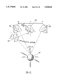
- FIG. 1 is a perspective view of the preferred laser localization apparatus of the present invention showing a fixed centrally disposed light source, and two additional light sources;
- FIG. 2 is a diagram of the invention showing horizontal laser tracks with a fixed centrally disposed light source and two additional light sources;
- FIG. 3 is a diagram of the invention of FIG. 2 showing the localization of the top of a tumor
- FIG. 4 is a diagram of the invention of FIG. 2 showing the localization of the bottom of the tumor
- FIG. 5 is a diagram of the invention of FIG. 2 showing an alternative localization of the top and bottom of a tumor
- FIG. 6 is a diagram of the invention of FIG. 2 showing the localization of the sides or the width of the tumor;
- FIG. 7 is a front view of the preferred frame system of the present invention.
- FIG. 8 is an end view of the frame system of FIG. 7;
- FIG. 9 is a cross-sectional view along section 80--80 of FIG. 7;
- FIG. 10 is a cross-sectional view along section 90--90 of FIG. 7;
- FIG. 11 is a side plan view of the spindle of FIG. 7;
- FIG. 12 is a cross-sectional side view of the spindle of FIG. 7;
- FIG. 13 is a top view of the spindle of FIG. 7;
- FIG. 14 is a top view of the markings shown on the top of the spindle of FIG. 13;
- FIG. 15 is a side plan view of the shaft of FIG. 7;
- FIG. 16 is a side view of the shaft of FIG. 7 showing markings
- FIG. 17 is a top view of the shaft of FIG. 7;
- FIG. 18 is a top view of the adjusting or mounting stage of FIG. 7;
- FIG. 19 is a top view of one of the side horizontal wings of FIG. 7, showing markings;
- FIG. 20 is a front view of one of the pointers of the focusing lens assembly bracket of FIG. 7, showing a marking
- FIG. 21 is a front view of one of the focusing lens assembly brackets of FIG. 7;
- FIG. 22 is a side view of the focusing lens assembly bracket shown in FIG. 21;
- FIG. 23 is a top view of the focusing lens assembly bracket shown in FIG. 21;
- FIG. 24 is a front view of one of the vertical azimuth bezels of FIG. 7, showing markings;
- FIG. 25 is a front view of one of the vertical azimuth bezels of FIG. 7;
- FIG. 26 is a side view of the vertical azimuth bezel of FIG. 25;
- FIG. 27 is a front view of one of the horizontal bezel carriages of FIG. 7, showing markings;
- FIG. 28 is a front view of one of the horizontal bezel carriages of FIG. 7;
- FIG. 29 is a top view of the horizontal bezel carriage of FIG. 28;
- FIG. 30 is a side view of the horizontal bezel carriage of FIG. 28;
- FIG. 31 is an alternative embodiment of the invention showing a worm gear used for adjustments along the horizontal wings;
- FIG. 32 is a perspective view of an alternative laser localization apparatus of the present invention showing a fixed centrally disposed light source and three additional light sources;
- FIG. 33 illustrates a preferred hardware block diagram in accordance with the invention
- FIG. 34 is an alternative microscope embodiment of the invention.
- FIGS. 35-37 are diagrams of the light source and prism operation within the microscope embodiment of FIG. 34;
- FIG. 38 is an alternative embodiment of the beam localization apparatus of the invention which incorporates an articulating robotic: type arm;
- FIG. 39 is an alternative embodiment of the microscope embodiment of the invention which incorporates an articulating robotic type arm attached to the base ring of a stereotactic frame apparatus.
- the beam localization apparatus and method of the present invention utilize several spaced beam sources for three-dimensional localization and measurement of lesions, tumors, abnormalities, structures, and the like (generally referred to herein as “lesions” or “tumors”), in a selected part of a human or animal body, particularly in a brain, (generally referred to in the specification and claims as “entity”, “volumetric entity” or “area to be measured” or “volume to be measured” or “brain”).
- the invention is particularly useful in conjunction with a medical stereotactic frame.
- stereotactic frame is customarily used in the art to denote a stereotactic frame attachable to a head
- this term for the purposes of the present invention, means a frame which is attachable to any part of the body.
- the invention is not limited to surgical or diagnostic methods for the head or brain, but can also be used on other parts of the body, e.g. the spine, with a frame system suitable for such body parts (e.g. a cylindrical coordinate system for a spinal stereotactic frame).
- beam as used throughout the specification and claims is intended to include all useful beams and rays, such as laser beams, x-ray beams, heavy particle beams, anti-matter beams, proton beams, gamma beams, ultrasonic beams, infrared beams, nuclear rays, other beams and rays, and the like.
- the preferred embodiment shown in the drawing utilizes laser beams, but the invention is not limited to the use of light beams.
- the invention involves a central light beam from a beam emitting source, such as a laser, which is projected along a previously determined stereotactic radian along the course of which the selected volumetric entity of the body may be located.
- a beam emitting source such as a laser
- Adjacent to this central beam source are several (preferably at least two) additional side beam emitting sources which emit "side beams", such as laser beams, which are projected from known positions relative to the central beam source.
- side beams such as laser beams
- the side beam sources are moveable along such arcs or tangents so that they can be positioned accurately in relationship to the central beam source.
- the central beam and the side beam can originate from a single source and by using optical equipment, such as mirrors, prisms, and lasers, can be made to project from three spaced points.
- the beams can alternatively originate from two, three or more sources and rely on mirrors, prisms, or lasers.
- Laser diodes can be used to provide the beams.
- the angles of the side beams are variable in a number of fashions so that they can be made to intersect the central beam at varying points along the central beam's trajectory.
- This capability allows calculations of depths along the trajectory of the central beam for determining the near and far positions of the volume of the selected volumetric entity of the body, such as an intracerebral structure and/or lesion, in three-dimensional space such calculations are performed by proportional angulations. Also derived from the ability to vary the angles of the additional or side beams is the capacity to determine the projected boundaries of the volume of the lesion in three-dimensional space in a full spherical manner. Measurements of a three-dimensional volume can be determined from various angles of beam intersection as discussed below.
- FIGS. 1-30 illustrate a preferred embodiment of a localization laser apparatus of the present invention comprising a beam localization frame system 10 having a centrally disposed, fixed light source 12 and two moveable side light sources 14 and 16 disposed on side horizontal wings or tracks 18 and 26, which are attachable to a stereotactic frame 9 (see FIG. 1).
- the stereotactic frame 9 may be one which is commonly available in the art.
- Centrally disposed light source 12 is preferably mounted in a fixed, centrally disposed position.
- Side light sources 14 and 16 each have horizontal motion along the horizontal tracks 18 and 26 independent of centrally disposed light source 12 and each other.
- light sources 14 and 16 are each independently, pivotally moveable in order to enable the surgeon or health practitioner to change the angle of each of their respective laser localization beams from a vertical aim through a 90° arc crossing the fixed vertical beam from light source 12.
- the light beams emitted from light sources 12, 14, and 16 are shown by dashed lines in the drawings.
- FIGS. 2-6 illustrate, simply, how side light sources 14 and 16 (shown as points and also sometimes referred to as "points” in the specification and claims) move pivotally relative to centrally disposed, fixed light source 12 (also shown as a point) in the localization of a hypothetical tumor 20 (shown by a round circle).
- FIG. 2 illustrates all light beams from the light points or sources 12, 14, and 16 having a vertical aim.
- the side light sources 14 and 16 can pivot through a 90° arc (shown by the angle ⁇ markings on (FIG. 2).
- FIG. 2 also illustrates a range of possible horizontal movement (denoted as "d") for the side light sources 14 and 16, relative to the centrally disposed light source 12, along the side horizontal tracks 18 and 26 (shown by lines).
- FIGS. 3-6 illustrate the intersection of the beams for the localization of the tumor 20.
- centrally disposed beam source 12 has its beam aimed at the center of the tumor 20.
- Side beam sources 14 and 16 emit beams which intersect with the central beam from central beam source 12 to define the top, bottom, sides and general positioning of the tumor 20.
- FIG. 3 illustrates beams from side beam sources 14 and 16 intersecting the beam from centrally disposed source 12 to define the top of the tumor 20.
- FIG. 4 illustrates beams from side beam sources 14 and 16 intersecting the beam from centrally disposed beam source 12 to define the bottom of the tumor 20.
- FIG. 5 illustrates an alternative method of defining the top and bottom of the tumor 20 with the intersection of the side beams with the central beam.
- FIG. 6 illustrates beams from side beam sources 14 and 16 intersecting with the central beam from beam source 12 to define the edges or sides of the tumor 20.
- Side beam sources 14 and 16 are rotatable on a tangential plane all or a portion of 360° around central beam source 12. Hence, tumors or lesions of varying widths can be measured and located.
- these diagrams illustrate generally a two-dimensional working of the invention, those skilled in the art can appreciate that the side beam sources 14 and 16 are independently rotatable all or a portion of 360° on a tangential plane around the central beam source 12 and that more than two additional or side beam sources may be utilized in practicing the invention (e.g., see FIG. 32) to provide more precise localization and measurements.
- a centrally fixed beam source and one additional beam source or two variable beam sources may be used to practice the invention, using proportional angulation methods to make determinations, although such determinations will not be as precise as those obtained by utilizing three or more beam sources.
- the present invention using angulational determinations of three-dimensional spatial volumetrics and position can aid the surgeon or health practitioner to: (1) directly indicate the position of e.g. an underlying intracranial/intracerebral structure, such as a lesion or tumor within the confines of the skull, so that the size and position of an opening, such as a cranial opening, can be accurately tailored; (2) accurately determine the location of the lesion or tumor; (3) accurately determine for simulation with computer graphics simulation methodology, gravitational and positional shifts of the lesion or tumor; and (4) accurately measure the depth, width, and volume of the tumor or lesion.
- an underlying intracranial/intracerebral structure such as a lesion or tumor within the confines of the skull
- an opening such as a cranial opening
- Desired information about the tumor is determined by proportional angulation methods using information about the positions of the beam sources, the positions of the beam sources relative to one another, and the directions of the beams from the beam sources. Information about a point, area or volume of the tumor can thereby be determined using a series of selected data points.
- a preferred three-dimensional laser localization apparatus is shown in the perspective view of FIG. 1, and in greater detail in the plan views of FIGS. 7-30.
- the beam localization frame system 10 of the invention is attachable as a separate apparatus onto a stereotactic probe holder device or on a typical stereotactic frame 9.
- the present invention comprises a central light emitting source 12, such as a laser light source, and two or more additional or side light emitting sources 14 and 16 which are independently movable away from and towards the central light emitting source 12, along a tangent bar or arc of the frame system 10, such as on a horizontal wing or track 18 and 26.
- the side light sources 14 and 16 can be moved along a tangent or an arc carrier anywhere within a tangential plane or arc relative to the central light source 12.
- the side light sources 14 and 16 are also preferably adjustably variable in an angular or pivotally rotatable fashion by micrometer or digital positioning so that their relationships of beam intersection with the beam from the central light source 12 can be varied or changed within highly accurate parameters.
- FIGS. 7 and 8 illustrate front and side views, respectively, of the preferred beam localization frame system 10 of the invention.
- FIGS. 9 and 10 illustrate cross-sectional views of sections 80--80, and 90--90, respectively, of FIG. 7.
- the two ends or sides of the beam localization frame system 10 are substantially similar and thus the discussion below which is applicable to one end only is also applicable, in general, to the other end.
- the beam localization frame system 10 comprises a centrally disposed shaft system 22 and a centrally disposed laser light mount 47 for mounting the central, fixed light source 12 and allowing the centrally disposed fixed light beam emitted therefrom to be emitted via central light emitting channel 24 (see FIGS.
- FIG. 8 and 9 respectively show side horizontal wings 18 and 26 for mounting the side light sources 14 and 16 and allowing the light beams emitted therefrom to be emitted via separate light emitting channels 28 (see FIG. 10).
- the vertical aim of all light beams is preferably aligned.
- FIG. 9 shows the central shaft 22 affixed to the beam localization frame system 10 by various set screws 29, 29' and 29". Set screw 29" is preferably recessed to avoid protrusion and obstruction of use of the frame 10.
- the side horizontal wings 18 and 26 are independently rotatably and movably mounted above a spindle 30.
- FIG. 10 shows the relationship among a locking plate 32 with set screw 33, the side horizontal wing 26, a horizontal bezel carriage 34, a vertical azimuth bezel 36, a pivot pin 38, a pivot locking screw and washer 39, a focusing lens assembly bracket 40 which carries the side light emitting channel 28, and a holding screw 42.
- a bezel locking screw 44 assists in holding the vertical azimuth bezel 36 to the focusing lens assembly bracket (see FIGS. 7 and 8).
- the focusing lens assembly bracket 40 which is fixed relative to the vertical azimuth bezel 36, can pivot, as adjusted by the surgeon, relative to the horizontal bezel carriage 34 which is affixed to the side horizontal mounting wing 18 or 26 and the locking plate 32.
- a sloped pointer 41 shows the surgeon the angle of the beam being emitted from the light emitting source 16 via the side light emitting channel 28.
- Bezel locking screw 44 which slides in sectional circular slot 46 disposed in the vertical azimuth bezel 36, holds the vertical azimuth bezel 36 and horizontal bezel carriage 34 in place along the horizontal wing 18 or 26 after the desired position is obtained, by compressing the vertical azimuth bezel 36 against the horizontal bezel carriage 34.
- FIGS. 11 and 12 show side views of the spindle 30, FIG. 13 shows a top view of the spindle 30, FIG. 15 shows a side view of the central shaft 22, and FIG. 17 shows a top view of the central shaft 22 of the preferred embodiment of the invention (also see FIGS. 8 and 9).
- the spindle 30 is rotatably disposed within the central shaft 22 (see FIG. 9).
- the horizontal wings 18 and 26 are rotatably disposed around the spindle 30 (see FIG. 9). Markings, preferably showing a 360° rotation, are present on the top of the spindle 30, as shown in a detailed top view of the spindle in FIG. 14. Likewise, markings may be present on the side of the central shaft 22, such as shown in FIG. 16, and on the horizontal side wings 18 and 26, such as shown in FIG. 19.
- FIG. 18 shows a top view of the central mount 47.
- a circular plate 53 has six holes 51,55 unequally spaced such that three holes 55 can be aligned and regularly realigned in the same position to sit atop the shaft 22 (also see FIG. 17); thus the plate 53 is always put on the same way.
- the additional three holes 51 carry hexhead screws which push the plate 53 away from the mounting face while the other three holes 55 carry hexhead screws which pull the plate 53 toward the mounting surface.
- This push/pull arrangement provides for greater calibration.
- the mounting plate 53 also has a D-shaped hole 57 in the center in which the laser light is directly mounted, thus preventing rotation of the light once it is fixed in place.
- FIGS. 20-30 More detailed drawings of some of the side light source mounting and calibration members shown in FIG. 10 are shown in FIGS. 20-30.
- the pointer 41 of the focusing lens assembly bracket 40 may have a vertical line 48 at the apex 50, as shown in FIG. 20.
- the vertical azimuth bezel 36 may have Vernier scale markings, such as shown in FIG. 24.
- the horizontal bezel carriage 34 may have Vernier scale markings, such as shown in FIG. 27. All of these markings, including the markings on the spindle 30, the central shaft 22 and the side horizontal wings 18 and 26, assist the surgeon or health practitioner to accurately take measurements and thereby determine the location and volume of the tumor or lesion.
- the focusing lens bracket assembly 40 has a D-shaped hole 61 disposed at its center, such as shown in FIG. 23, which is used for mounting the lateral light sources.
- small hexhead set screws 63,65 which push and pull the focusing lens bracket assembly 40, respectively, relative to the vertical azimuth bezel 36 provide for enhanced calibration and accuracy of the laser light trajectories when angles are changed.
- FIGS. 24-26 Detailed drawings of the vertical azimuth bezel 36 are shown in FIGS. 24-26 and detailed drawings of the horizontal azimuth bezel carriage 34 are shown in FIGS. 27-30.
- FIG. 25 shows a front view
- FIG. 26 shows a side view
- FIG. 24 shows the markings on a front view, of the vertical azimuth bezel 36.
- FIG. 27 shows the markings on a front view
- FIG. 28 shows a front view
- FIG. 29 shows a top view
- FIG. 30 shows a side view of the horizontal bezel carriage 34.
- Set screws 43 disposed on the horizontal azimuth bezel carriage 34, as shown in FIG. 28, are disposed in circular sectional slot 46 disposed in the vertical azimuth bezel 36, as shown in FIG. 25.
- side light sources 14 and 16 are adjusted by use of a worm gear 90 which is attached to the horizontal wings 18 and 26 and side light sources 14 and 16.
- a worm gear 90 which is attached to the horizontal wings 18 and 26 and side light sources 14 and 16.
- other means of moving side light sources 14 and 16 may be utilized in accordance with the invention, and the invention is not limited to the embodiments shown in the drawings.
- FIG. 32 illustrates an alternative embodiment of the invention, wherein there are three "side" light sources 14, 16, and 52, in addition to the centrally disposed light source 12. All of the discussion above pertains to this alternative embodiment, except there is an additional wing 54 which comprises the third side light source 52.
- the additional light source 52 enables the practitioner to make even more accurate determinations and measurements.
- the invention is not limited to three or four spaced light sources, but may comprise as many light sources as the practitioner may desire to make accurate determinations and measurements.
- FIG. 33 illustrates a preferred hardware block diagram in accordance with the invention.
- Scanners 56 such as CT, magnetic resonance imaging (MRI), PET, DSA, X-ray and various isotope scanners, are provided to obtain various scanning data.
- This scanning data which is in various, typically non-standard formats, is convertible to a standard format in accordance with the invention using a PROM computer video signal processor 58.
- Standard formats which can be used include, but are not limited to, RS-170, CCIR 625 I, RS-343, RS-422, and NTSC.
- the scanning data may be provided to the computer video signal processor 58 from the scanners 56 by, for example, a BNC connector.
- the converted scanning data are made available, through programmable relay control 60, to a central processing unit (CPU) 62, such as a 68020/030 VME BUS based CPU with a clock speed up to 30 MHz, preferably comprising hard disk storage, floppy disk storage, streamer tape storage, and a high-resolution frame grabber with a high speed graphics and video image processor.
- CPU central processing unit
- the programmable relay control 60 sets the scanner converter input/output parameters to acquire and convert scanner image data from their various formats to a standard format, for use by the system in accordance with the invention.
- a scanner converter automatically senses signal input and sets parameters for conversion to a standard format, without the use of user-selectable switches.
- a user input device 68 such as a high-resolution infrared touch screen and a monitor 66, both connected to the CPU 62, enable the user to selectively manipulate and display the image data.
- the monitor 66 is preferably a high-resolution color graphics monitor with video inputs for red, green, blue, and composite video signals.
- the monitor 66 can be configured to operate in either interlaced or non-interlaced mode. Copies of images on the monitor can be provided using a hard copy device 70, such as a high-resolution color videocopy unit.
- Software provided in the CPU 62, is preferably structured on a multi-modular bi-divisional foundation, which comprises a division for image acquisition, enhancement, and manipulation and a division for graphics and user-specific functions.
- the division for image acquisition, enhancement, and manipulation includes modular software subroutines for: 1) image capture, storage, and achieving; 2) pixel analysis for an entire image or user-defined areas of interest; 3) zoom and pan functions; 4) contrasting and filtering images with functions for smoothing, sharpening, and pseudocoloring; 5) image comparisons; 6) image editing; and 7) various edge detection routines, including Laplacian, Roberts, Sorbel, and Frei routines.
- the graphics and user-specific functions comprise software modular subroutines that control: 1) the manipulation and swapping of diencephalic and brain-stem atlas maps (preferably at least 117 of such maps) in frontal, sagittal, and horizontal sections; 2) the graphic simulation and the manipulation of various probes and electrodes; 3) alphanumeric functions for demographic data and for coding, storing, and selectively displaying the position of various electrophysiological response points on an electrophysiological map system which preferably comprises at least 2500 electrophysiological response points; 4) measurement functions for determining stereotactic coordinates and other user-specific calculations; and 5) volumetric determinations and two- or three-dimensional simulations.
- the three-dimensional laser localization apparatus for stereotactic surgery is attached to and incorporated within the optics of a surgical dissecting microscope 153.
- This embodiment requires that the microscope objective lens 155 be attached to the arc carrier of the stereotactic surgical frame.
- This embodiment allows for smaller openings, such as for cranial and cerebral openings, for surgical approach to deep-seated intracranial or intracerebral structures and/or lesions.
- the laser light sources are delivered by an optical prismatic system designed such that the primary laser light source is split into at least three separate laser light beams (shown by dashed lines) which project from the microscope's objective lens 155.
- the prismatic system is designed such that by micrometer and/or digital adjustments the additional (preferably at least two) laser light sources are movable around at an angle in relation to the central laser light beam.
- FIGS. 35-37 schematically show the relationships, in this alternative embodiment, among a fixed position light source 156; a first additional variable light source 158, preferably with micrometer or digital adjustment along axes A, B, and C; a second additional variable light source 160, preferably with micrometer or digital adjustment along axes A, B, and C; a rotation prism. 162; and a hypothetical tumor 164.
- FIGS. 35-37 illustrate the localization of the sides, center and top of the tumor 164, respectively, by the angular rotation of the prism 162 (preferably 360'), the angles between the laser beams, shown as " ⁇ ", “ ⁇ "'", and “ ⁇ R ", and the distance between the light sources on the microscope objective mount, shown as ⁇ d" in these figures.
- this microscope embodiment may comprise more than two additional variable light sources, such as discussed with reference to the preferred embodiment.
- the three-dimensional beam localization apparatus as shown in FIG. 38, or the microscope embodiment, as shown in FIG. 39, can be attached to an articulating robotic type arm 100.
- This embodiment allows attachment to any component of a stereotactic localization system, such as a surgical headrest/bodyrest fixation system, the operating room table, or the base ring of a stereotactic apparatus 102, as shown in FIG. 39, and therefore allows a greater range of motion than may be possible with other embodiments of the invention.
- the purpose of the robotic arm is to provide means for spatial referencing and positioning.
- infrared or ultrasonic sensing and emitting devices may be employed to spatially locate and assist positioning of the microscope or beam localization embodiment in stereotactic space. This would obviate the need for a robotic arm, or could be used in conjunction with a robotic arm.
- the preferred light source is a laser light source.
- the light beams can be transmitted by means common to the art, preferably by either one of two fashions.
- the laser may be connected by special optic coupling to fine fiber-optic cabling to which a lens system is attached to the associated fiber-optic cabling for projecting the laser light beam.
- One such fiber-optic laser light linkage for each laser light source is attached to the laser light carrier on the stereotactic frame system.
- the primary source of all laser light may be from miniaturized laser diodes having the laser light source and lens system incorporated into the laser diodes for projection of the laser light. These sources are connected by special coupling to the laser light carrier on the stereotactic frame system.
- Each laser diode has connected to it an associated electrical power supply cabling.
- the preferred laser light sources are helium-neon lasers, although other suitable laser systems known in the art could also be utilized.
- other laser systems should be selected depending on what techniques are to be performed, for instance whether the surgeon or health practitioner is to perform diagnostic techniques or surgical techniques. Too, the light sources can be of the same or different colors or wavelengths to provide for ease of use and accuracy.
- the invention further comprises a method of determining desired information about a volumetric entity in a body. This method comprises the following steps:
- Steps b) and c) may be repeated a multiplicity of times to a series of points on an area or volume of the volumetric entity to determine positional, area, and volumetric information about the volumetric entity.
Abstract
Description
Claims (27)
Priority Applications (1)
| Application Number | Priority Date | Filing Date | Title |
|---|---|---|---|
| US07/936,797 US5354314A (en) | 1988-12-23 | 1992-08-28 | Three-dimensional beam localization apparatus and microscope for stereotactic diagnoses or surgery mounted on robotic type arm |
Applications Claiming Priority (4)
| Application Number | Priority Date | Filing Date | Title |
|---|---|---|---|
| US07/290,316 US5099846A (en) | 1988-12-23 | 1988-12-23 | Method and apparatus for video presentation from a variety of scanner imaging sources |
| US42824289A | 1989-10-27 | 1989-10-27 | |
| US07/552,256 US5176689A (en) | 1988-12-23 | 1990-07-11 | Three-dimensional beam localization apparatus for stereotactic diagnoses or surgery |
| US07/936,797 US5354314A (en) | 1988-12-23 | 1992-08-28 | Three-dimensional beam localization apparatus and microscope for stereotactic diagnoses or surgery mounted on robotic type arm |
Related Parent Applications (1)
| Application Number | Title | Priority Date | Filing Date |
|---|---|---|---|
| US07/552,256 Continuation-In-Part US5176689A (en) | 1988-12-23 | 1990-07-11 | Three-dimensional beam localization apparatus for stereotactic diagnoses or surgery |
Publications (1)
| Publication Number | Publication Date |
|---|---|
| US5354314A true US5354314A (en) | 1994-10-11 |
Family
ID=46246798
Family Applications (1)
| Application Number | Title | Priority Date | Filing Date |
|---|---|---|---|
| US07/936,797 Expired - Fee Related US5354314A (en) | 1988-12-23 | 1992-08-28 | Three-dimensional beam localization apparatus and microscope for stereotactic diagnoses or surgery mounted on robotic type arm |
Country Status (1)
| Country | Link |
|---|---|
| US (1) | US5354314A (en) |
Cited By (148)
| Publication number | Priority date | Publication date | Assignee | Title |
|---|---|---|---|---|
| US5452720A (en) * | 1990-09-05 | 1995-09-26 | Photoelectron Corporation | Method for treating brain tumors |
| EP0821916A2 (en) * | 1996-07-29 | 1998-02-04 | MRC Systems GmbH MR-kompatible chirurgische Systeme | Method for performing stereotactic laser surgery |
| US5794621A (en) * | 1995-11-03 | 1998-08-18 | Massachusetts Institute Of Technology | System and method for medical imaging utilizing a robotic device, and robotic device for use in medical imaging |
| US5795295A (en) * | 1996-06-25 | 1998-08-18 | Carl Zeiss, Inc. | OCT-assisted surgical microscope with multi-coordinate manipulator |
| US5810674A (en) * | 1996-02-16 | 1998-09-22 | Falossi; Aldo | Light emitting positioning system |
| US6006126A (en) | 1991-01-28 | 1999-12-21 | Cosman; Eric R. | System and method for stereotactic registration of image scan data |
| US6134294A (en) * | 1998-02-13 | 2000-10-17 | University Of Utah Research Foundation | Device and method for precision macular X-irradiation |
| US6132368A (en) * | 1996-12-12 | 2000-10-17 | Intuitive Surgical, Inc. | Multi-component telepresence system and method |
| US6167295A (en) | 1991-01-28 | 2000-12-26 | Radionics, Inc. | Optical and computer graphic stereotactic localizer |
| US6206891B1 (en) * | 1999-09-14 | 2001-03-27 | Medeye Medical Technology Ltd. | Device and method for calibration of a stereotactic localization system |
| US6275725B1 (en) | 1991-01-28 | 2001-08-14 | Radionics, Inc. | Stereotactic optical navigation |
| US6331181B1 (en) | 1998-12-08 | 2001-12-18 | Intuitive Surgical, Inc. | Surgical robotic tools, data architecture, and use |
| US6331180B1 (en) | 1988-05-03 | 2001-12-18 | Sherwood Services Ag | Target-centered stereotaxtic surgical arc system with reorientatable arc axis |
| US6402689B1 (en) | 1998-09-30 | 2002-06-11 | Sicel Technologies, Inc. | Methods, systems, and associated implantable devices for dynamic monitoring of physiological and biological properties of tumors |
| US20020099284A1 (en) * | 2000-11-17 | 2002-07-25 | Klaus Herrmann | Method and apparatus for characterizing a location at an examination subject |
| US6487438B1 (en) * | 1997-03-18 | 2002-11-26 | Beampoint Ab | Arrangement and reference means to direct a beam in radiation therapy |
| US6620173B2 (en) | 1998-12-08 | 2003-09-16 | Intuitive Surgical, Inc. | Method for introducing an end effector to a surgical site in minimally invasive surgery |
| US20030208187A1 (en) * | 2002-05-02 | 2003-11-06 | Gmp Surgical Solutions, Inc. | Apparatus for positioning a medical instrument |
| US20040054355A1 (en) * | 2001-05-31 | 2004-03-18 | Intuitive Surgical, Inc. | Tool guide and method for introducing an end effector to a surgical site in minimally invasive surgery |
| US20040092958A1 (en) * | 2001-11-15 | 2004-05-13 | Limonadi Farhad M. | Stereotactic wands, endoscopes and methods using such wands and endoscopes |
| US20040122311A1 (en) * | 1991-01-28 | 2004-06-24 | Cosman Eric R. | Surgical positioning system |
| US6783524B2 (en) | 2001-04-19 | 2004-08-31 | Intuitive Surgical, Inc. | Robotic surgical tool with ultrasound cauterizing and cutting instrument |
| US6826423B1 (en) | 1999-01-04 | 2004-11-30 | Midco-Medical Instrumentation And Diagnostics Corporation | Whole body stereotactic localization and immobilization system |
| US6840938B1 (en) | 2000-12-29 | 2005-01-11 | Intuitive Surgical, Inc. | Bipolar cauterizing instrument |
| US20050055035A1 (en) * | 2003-05-23 | 2005-03-10 | Cosman Eric Richard | Image-based stereotactic frame for non-human animals |
| US20050094260A1 (en) * | 2003-10-17 | 2005-05-05 | Olympus Corporation | Objective lens unit, objective lens insertion tool, microscope, objective optical system fixing device, and microscope system |
| US20050251110A1 (en) * | 2004-05-04 | 2005-11-10 | Intuitive Surgical, Inc. | Tool grip calibration for robotic surgery |
| US7011814B2 (en) | 2001-04-23 | 2006-03-14 | Sicel Technologies, Inc. | Systems, methods and devices for in vivo monitoring of a localized response via a radiolabeled analyte in a subject |
| US20070005045A1 (en) * | 2005-06-30 | 2007-01-04 | Intuitive Surgical Inc. | Indicator for tool state and communication in multi-arm robotic telesurgery |
| US7378056B2 (en) | 2000-11-09 | 2008-05-27 | Sicel Technologies, Inc. | Circuits for in vivo detection of biomolecule concentrations using fluorescent tags |
| US7491942B2 (en) | 2001-11-30 | 2009-02-17 | Sicel Technologies, Inc. | Single-use internal dosimeters for detecting radiation in fluoroscopy and other medical procedures/therapies |
| US7510699B2 (en) | 2003-02-19 | 2009-03-31 | Sicel Technologies, Inc. | In vivo fluorescence sensors, systems, and related methods operating in conjunction with fluorescent analytes |
| US20090091708A1 (en) * | 2007-10-05 | 2009-04-09 | Los Alamos National Security, Llc | Presentation device for stereoscopic applications |
| US7862580B2 (en) | 2002-12-06 | 2011-01-04 | Intuitive Surgical Operations, Inc. | Flexible wrist for surgical tool |
| CN102755195A (en) * | 2011-04-29 | 2012-10-31 | 陈德路 | Tumor isocenter multi-angle non-planar percutaneous puncture method |
| US20130066305A1 (en) * | 2011-07-08 | 2013-03-14 | Todd Bjork | Minimally invasive portal system |
| US8442661B1 (en) * | 2008-11-25 | 2013-05-14 | Anybots 2.0, Inc. | Remotely controlled self-balancing robot including a stabilized laser pointer |
| US20130331685A1 (en) * | 2012-06-08 | 2013-12-12 | Chang Gung University | Neuronavigation-guided focused ultrasound system and method thereof |
| US20140005555A1 (en) * | 2012-06-27 | 2014-01-02 | CamPlex LLC | Optical assembly providing a surgical microscope view for a surgical visualization system |
| US8788096B1 (en) | 2010-05-17 | 2014-07-22 | Anybots 2.0, Inc. | Self-balancing robot having a shaft-mounted head |
| US20140257290A1 (en) * | 2013-03-08 | 2014-09-11 | Ta-Lun Tan | Intramedullary apparatus and methods of treating bone fracture using the same |
| US8894634B2 (en) | 2005-06-30 | 2014-11-25 | Intuitive Surgical Operations, Inc. | Indicator for tool state and communication in multi-arm robotic telesurgery |
| US8911428B2 (en) | 2001-06-29 | 2014-12-16 | Intuitive Surgical Operations, Inc. | Apparatus for pitch and yaw rotation |
| US8998930B2 (en) | 2005-12-20 | 2015-04-07 | Intuitive Surgical Operations, Inc. | Disposable sterile surgical adaptor |
| US8998799B2 (en) | 1996-12-12 | 2015-04-07 | Intuitive Surgical Operations, Inc. | Sterile surgical adaptor |
| US9005112B2 (en) | 2001-06-29 | 2015-04-14 | Intuitive Surgical Operations, Inc. | Articulate and swapable endoscope for a surgical robot |
| US9078685B2 (en) | 2007-02-16 | 2015-07-14 | Globus Medical, Inc. | Method and system for performing invasive medical procedures using a surgical robot |
| US9320568B2 (en) | 1997-11-21 | 2016-04-26 | Intuitive Surgical Operations, Inc. | Sterile surgical drape |
| US9375844B2 (en) | 2013-03-15 | 2016-06-28 | Intuitive Surgical Operations, Inc. | Geometrically appropriate tool selection assistance for determined work site dimensions |
| US9435612B2 (en) | 2012-11-02 | 2016-09-06 | Umarex Usa, Inc. | Method and system for aligning a point of aim with a point of impact for a projectile device |
| US9439732B2 (en) | 1996-12-12 | 2016-09-13 | Intuitive Surgical Operations, Inc. | Instrument interface of a robotic surgical system |
| US9532849B2 (en) | 1997-11-21 | 2017-01-03 | Intuitive Surgical Operations, Inc. | Surgical accessory clamp and system |
| US9642606B2 (en) | 2012-06-27 | 2017-05-09 | Camplex, Inc. | Surgical visualization system |
| US9782229B2 (en) | 2007-02-16 | 2017-10-10 | Globus Medical, Inc. | Surgical robot platform |
| US9782159B2 (en) | 2013-03-13 | 2017-10-10 | Camplex, Inc. | Surgical visualization systems |
| US9860510B2 (en) | 2013-03-15 | 2018-01-02 | Intuitive Surgical Operations, Inc. | Depth based modification of captured images |
| US10028651B2 (en) | 2013-09-20 | 2018-07-24 | Camplex, Inc. | Surgical visualization systems and displays |
| US10080615B2 (en) | 2015-08-12 | 2018-09-25 | Globus Medical, Inc. | Devices and methods for temporary mounting of parts to bone |
| US10117632B2 (en) | 2016-02-03 | 2018-11-06 | Globus Medical, Inc. | Portable medical imaging system with beam scanning collimator |
| US10136954B2 (en) | 2012-06-21 | 2018-11-27 | Globus Medical, Inc. | Surgical tool systems and method |
| US10231791B2 (en) | 2012-06-21 | 2019-03-19 | Globus Medical, Inc. | Infrared signal based position recognition system for use with a robot-assisted surgery |
| US10292778B2 (en) | 2014-04-24 | 2019-05-21 | Globus Medical, Inc. | Surgical instrument holder for use with a robotic surgical system |
| US10357184B2 (en) | 2012-06-21 | 2019-07-23 | Globus Medical, Inc. | Surgical tool systems and method |
| US10417357B2 (en) | 2012-03-08 | 2019-09-17 | Neutar, Llc | Patient and procedure customized fixation and targeting devices for stereotactic frames |
| US10448910B2 (en) | 2016-02-03 | 2019-10-22 | Globus Medical, Inc. | Portable medical imaging system |
| US10568499B2 (en) | 2013-09-20 | 2020-02-25 | Camplex, Inc. | Surgical visualization systems and displays |
| US10569794B2 (en) | 2015-10-13 | 2020-02-25 | Globus Medical, Inc. | Stabilizer wheel assembly and methods of use |
| US10573023B2 (en) | 2018-04-09 | 2020-02-25 | Globus Medical, Inc. | Predictive visualization of medical imaging scanner component movement |
| US10580217B2 (en) | 2015-02-03 | 2020-03-03 | Globus Medical, Inc. | Surgeon head-mounted display apparatuses |
| US10646283B2 (en) | 2018-02-19 | 2020-05-12 | Globus Medical Inc. | Augmented reality navigation systems for use with robotic surgical systems and methods of their use |
| US10660712B2 (en) | 2011-04-01 | 2020-05-26 | Globus Medical Inc. | Robotic system and method for spinal and other surgeries |
| US10675094B2 (en) | 2017-07-21 | 2020-06-09 | Globus Medical Inc. | Robot surgical platform |
| US10702353B2 (en) | 2014-12-05 | 2020-07-07 | Camplex, Inc. | Surgical visualizations systems and displays |
| US10813704B2 (en) | 2013-10-04 | 2020-10-27 | Kb Medical, Sa | Apparatus and systems for precise guidance of surgical tools |
| US10842453B2 (en) | 2016-02-03 | 2020-11-24 | Globus Medical, Inc. | Portable medical imaging system |
| US10866119B2 (en) | 2016-03-14 | 2020-12-15 | Globus Medical, Inc. | Metal detector for detecting insertion of a surgical device into a hollow tube |
| US10893912B2 (en) | 2006-02-16 | 2021-01-19 | Globus Medical Inc. | Surgical tool systems and methods |
| US10898252B2 (en) | 2017-11-09 | 2021-01-26 | Globus Medical, Inc. | Surgical robotic systems for bending surgical rods, and related methods and devices |
| US10918455B2 (en) | 2017-05-08 | 2021-02-16 | Camplex, Inc. | Variable light source |
| US10925681B2 (en) | 2015-07-31 | 2021-02-23 | Globus Medical Inc. | Robot arm and methods of use |
| US10939968B2 (en) | 2014-02-11 | 2021-03-09 | Globus Medical Inc. | Sterile handle for controlling a robotic surgical system from a sterile field |
| US10945742B2 (en) | 2014-07-14 | 2021-03-16 | Globus Medical Inc. | Anti-skid surgical instrument for use in preparing holes in bone tissue |
| US10966798B2 (en) | 2015-11-25 | 2021-04-06 | Camplex, Inc. | Surgical visualization systems and displays |
| US10973594B2 (en) | 2015-09-14 | 2021-04-13 | Globus Medical, Inc. | Surgical robotic systems and methods thereof |
| US11045179B2 (en) | 2019-05-20 | 2021-06-29 | Global Medical Inc | Robot-mounted retractor system |
| US11045267B2 (en) | 2012-06-21 | 2021-06-29 | Globus Medical, Inc. | Surgical robotic automation with tracking markers |
| US11058378B2 (en) | 2016-02-03 | 2021-07-13 | Globus Medical, Inc. | Portable medical imaging system |
| US11109922B2 (en) | 2012-06-21 | 2021-09-07 | Globus Medical, Inc. | Surgical tool systems and method |
| US11116576B2 (en) | 2012-06-21 | 2021-09-14 | Globus Medical Inc. | Dynamic reference arrays and methods of use |
| US11134862B2 (en) | 2017-11-10 | 2021-10-05 | Globus Medical, Inc. | Methods of selecting surgical implants and related devices |
| US11153555B1 (en) | 2020-05-08 | 2021-10-19 | Globus Medical Inc. | Extended reality headset camera system for computer assisted navigation in surgery |
| US11154378B2 (en) | 2015-03-25 | 2021-10-26 | Camplex, Inc. | Surgical visualization systems and displays |
| US11207150B2 (en) | 2020-02-19 | 2021-12-28 | Globus Medical, Inc. | Displaying a virtual model of a planned instrument attachment to ensure correct selection of physical instrument attachment |
| US11253327B2 (en) | 2012-06-21 | 2022-02-22 | Globus Medical, Inc. | Systems and methods for automatically changing an end-effector on a surgical robot |
| US11253216B2 (en) | 2020-04-28 | 2022-02-22 | Globus Medical Inc. | Fixtures for fluoroscopic imaging systems and related navigation systems and methods |
| US11266470B2 (en) | 2015-02-18 | 2022-03-08 | KB Medical SA | Systems and methods for performing minimally invasive spinal surgery with a robotic surgical system using a percutaneous technique |
| US11278360B2 (en) | 2018-11-16 | 2022-03-22 | Globus Medical, Inc. | End-effectors for surgical robotic systems having sealed optical components |
| US11298196B2 (en) | 2012-06-21 | 2022-04-12 | Globus Medical Inc. | Surgical robotic automation with tracking markers and controlled tool advancement |
| US11317973B2 (en) | 2020-06-09 | 2022-05-03 | Globus Medical, Inc. | Camera tracking bar for computer assisted navigation during surgery |
| US11317978B2 (en) | 2019-03-22 | 2022-05-03 | Globus Medical, Inc. | System for neuronavigation registration and robotic trajectory guidance, robotic surgery, and related methods and devices |
| US11317971B2 (en) | 2012-06-21 | 2022-05-03 | Globus Medical, Inc. | Systems and methods related to robotic guidance in surgery |
| US11337769B2 (en) | 2015-07-31 | 2022-05-24 | Globus Medical, Inc. | Robot arm and methods of use |
| US11337742B2 (en) | 2018-11-05 | 2022-05-24 | Globus Medical Inc | Compliant orthopedic driver |
| US11357548B2 (en) | 2017-11-09 | 2022-06-14 | Globus Medical, Inc. | Robotic rod benders and related mechanical and motor housings |
| US11382700B2 (en) | 2020-05-08 | 2022-07-12 | Globus Medical Inc. | Extended reality headset tool tracking and control |
| US11382549B2 (en) | 2019-03-22 | 2022-07-12 | Globus Medical, Inc. | System for neuronavigation registration and robotic trajectory guidance, and related methods and devices |
| US11382699B2 (en) | 2020-02-10 | 2022-07-12 | Globus Medical Inc. | Extended reality visualization of optical tool tracking volume for computer assisted navigation in surgery |
| US11382713B2 (en) | 2020-06-16 | 2022-07-12 | Globus Medical, Inc. | Navigated surgical system with eye to XR headset display calibration |
| US11395706B2 (en) | 2012-06-21 | 2022-07-26 | Globus Medical Inc. | Surgical robot platform |
| US11399900B2 (en) | 2012-06-21 | 2022-08-02 | Globus Medical, Inc. | Robotic systems providing co-registration using natural fiducials and related methods |
| US11419616B2 (en) | 2019-03-22 | 2022-08-23 | Globus Medical, Inc. | System for neuronavigation registration and robotic trajectory guidance, robotic surgery, and related methods and devices |
| US11426178B2 (en) | 2019-09-27 | 2022-08-30 | Globus Medical Inc. | Systems and methods for navigating a pin guide driver |
| US11439444B1 (en) | 2021-07-22 | 2022-09-13 | Globus Medical, Inc. | Screw tower and rod reduction tool |
| US11510684B2 (en) | 2019-10-14 | 2022-11-29 | Globus Medical, Inc. | Rotary motion passive end effector for surgical robots in orthopedic surgeries |
| US11510750B2 (en) | 2020-05-08 | 2022-11-29 | Globus Medical, Inc. | Leveraging two-dimensional digital imaging and communication in medicine imagery in three-dimensional extended reality applications |
| US11523785B2 (en) | 2020-09-24 | 2022-12-13 | Globus Medical, Inc. | Increased cone beam computed tomography volume length without requiring stitching or longitudinal C-arm movement |
| US11529195B2 (en) | 2017-01-18 | 2022-12-20 | Globus Medical Inc. | Robotic navigation of robotic surgical systems |
| US11571265B2 (en) | 2019-03-22 | 2023-02-07 | Globus Medical Inc. | System for neuronavigation registration and robotic trajectory guidance, robotic surgery, and related methods and devices |
| US11571171B2 (en) | 2019-09-24 | 2023-02-07 | Globus Medical, Inc. | Compound curve cable chain |
| US11602402B2 (en) | 2018-12-04 | 2023-03-14 | Globus Medical, Inc. | Drill guide fixtures, cranial insertion fixtures, and related methods and robotic systems |
| US11607149B2 (en) | 2012-06-21 | 2023-03-21 | Globus Medical Inc. | Surgical tool systems and method |
| US11628039B2 (en) | 2006-02-16 | 2023-04-18 | Globus Medical Inc. | Surgical tool systems and methods |
| US11628023B2 (en) | 2019-07-10 | 2023-04-18 | Globus Medical, Inc. | Robotic navigational system for interbody implants |
| US11717350B2 (en) | 2020-11-24 | 2023-08-08 | Globus Medical Inc. | Methods for robotic assistance and navigation in spinal surgery and related systems |
| US11737831B2 (en) | 2020-09-02 | 2023-08-29 | Globus Medical Inc. | Surgical object tracking template generation for computer assisted navigation during surgical procedure |
| US11737766B2 (en) | 2014-01-15 | 2023-08-29 | Globus Medical Inc. | Notched apparatus for guidance of an insertable instrument along an axis during spinal surgery |
| US11744655B2 (en) | 2018-12-04 | 2023-09-05 | Globus Medical, Inc. | Drill guide fixtures, cranial insertion fixtures, and related methods and robotic systems |
| US11793588B2 (en) | 2020-07-23 | 2023-10-24 | Globus Medical, Inc. | Sterile draping of robotic arms |
| US11794338B2 (en) | 2017-11-09 | 2023-10-24 | Globus Medical Inc. | Robotic rod benders and related mechanical and motor housings |
| US11793570B2 (en) | 2012-06-21 | 2023-10-24 | Globus Medical Inc. | Surgical robotic automation with tracking markers |
| US11806084B2 (en) | 2019-03-22 | 2023-11-07 | Globus Medical, Inc. | System for neuronavigation registration and robotic trajectory guidance, and related methods and devices |
| US11813030B2 (en) | 2017-03-16 | 2023-11-14 | Globus Medical, Inc. | Robotic navigation of robotic surgical systems |
| US11819365B2 (en) | 2012-06-21 | 2023-11-21 | Globus Medical, Inc. | System and method for measuring depth of instrumentation |
| US11850009B2 (en) | 2021-07-06 | 2023-12-26 | Globus Medical, Inc. | Ultrasonic robotic surgical navigation |
| US11857149B2 (en) | 2012-06-21 | 2024-01-02 | Globus Medical, Inc. | Surgical robotic systems with target trajectory deviation monitoring and related methods |
| US11857266B2 (en) | 2012-06-21 | 2024-01-02 | Globus Medical, Inc. | System for a surveillance marker in robotic-assisted surgery |
| US11864839B2 (en) | 2012-06-21 | 2024-01-09 | Globus Medical Inc. | Methods of adjusting a virtual implant and related surgical navigation systems |
| US11864857B2 (en) | 2019-09-27 | 2024-01-09 | Globus Medical, Inc. | Surgical robot with passive end effector |
| US11864745B2 (en) | 2012-06-21 | 2024-01-09 | Globus Medical, Inc. | Surgical robotic system with retractor |
| US11872000B2 (en) | 2015-08-31 | 2024-01-16 | Globus Medical, Inc | Robotic surgical systems and methods |
| US11877807B2 (en) | 2020-07-10 | 2024-01-23 | Globus Medical, Inc | Instruments for navigated orthopedic surgeries |
| US11883217B2 (en) | 2016-02-03 | 2024-01-30 | Globus Medical, Inc. | Portable medical imaging system and method |
| US11890066B2 (en) | 2019-09-30 | 2024-02-06 | Globus Medical, Inc | Surgical robot with passive end effector |
| US11911115B2 (en) | 2021-12-20 | 2024-02-27 | Globus Medical Inc. | Flat panel registration fixture and method of using same |
| US11911112B2 (en) | 2020-10-27 | 2024-02-27 | Globus Medical, Inc. | Robotic navigational system |
| US11911225B2 (en) | 2012-06-21 | 2024-02-27 | Globus Medical Inc. | Method and system for improving 2D-3D registration convergence |
| US11941814B2 (en) | 2020-11-04 | 2024-03-26 | Globus Medical Inc. | Auto segmentation using 2-D images taken during 3-D imaging spin |
| US11944325B2 (en) | 2019-03-22 | 2024-04-02 | Globus Medical, Inc. | System for neuronavigation registration and robotic trajectory guidance, robotic surgery, and related methods and devices |
Citations (45)
| Publication number | Priority date | Publication date | Assignee | Title |
|---|---|---|---|---|
| US3508552A (en) * | 1961-10-27 | 1970-04-28 | Alexandre & Cie | Apparatus for stereotaxic neurosurgery |
| US3783251A (en) * | 1970-11-27 | 1974-01-01 | Varian Associates | Computer assisted radiation therapy machine |
| US3987281A (en) * | 1974-07-29 | 1976-10-19 | The United States Of America As Represented By The Department Of Health, Education And Welfare | Method of radiation therapy treatment planning |
| US4079450A (en) * | 1975-03-12 | 1978-03-14 | Fraunhofer-Gesellschaft Zur Forderung Der Angewandten Forschung E.V. | Input-output-color-screen system |
| FR2384481A1 (en) * | 1977-03-25 | 1978-10-20 | Radiologie Cie Gle | Medical stereotaxic appts. - with spots from triple reflected laser beam focused together on target to provide accurate positioning |
| US4123143A (en) * | 1975-11-27 | 1978-10-31 | Laser Industries Ltd. | Laser beam aligning apparatus |
| US4223227A (en) * | 1978-06-22 | 1980-09-16 | William Beaumont Hospital | Laser alignment fixture |
| US4230117A (en) * | 1978-02-27 | 1980-10-28 | Anichkov Andrei D | Stereotaxic apparatus |
| US4259725A (en) * | 1979-03-01 | 1981-03-31 | General Electric Company | Cursor generator for use in computerized tomography and other image display systems |
| US4278888A (en) * | 1978-01-21 | 1981-07-14 | U.S. Philips Corporation | Apparatus for determining the spatial distribution of the absorption of radiation in a body |
| US4341220A (en) * | 1979-04-13 | 1982-07-27 | Pfizer Inc. | Stereotactic surgery apparatus and method |
| US4350159A (en) * | 1980-02-29 | 1982-09-21 | Gouda Kasim I | Frame for stereotactic surgery |
| US4386602A (en) * | 1977-05-17 | 1983-06-07 | Sheldon Charles H | Intracranial surgical operative apparatus |
| US4455609A (en) * | 1980-09-17 | 1984-06-19 | Nippon Electric Co., Ltd. | Apparatus for realtime fast reconstruction and display of dose distribution |
| US4463758A (en) * | 1981-09-18 | 1984-08-07 | Arun A. Patil | Computed tomography stereotactic frame |
| SU1074239A1 (en) * | 1982-04-07 | 1984-12-30 | Предприятие П/Я Ю-9733 | Scanning laser microscope |
| US4502147A (en) * | 1982-08-09 | 1985-02-26 | Charles Lescrenier | Means for visually indicating an X-ray field |
| US4583538A (en) * | 1984-05-04 | 1986-04-22 | Onik Gary M | Method and apparatus for stereotaxic placement of probes in the body utilizing CT scanner localization |
| US4597380A (en) * | 1982-09-30 | 1986-07-01 | Laser Industries Ltd. | Endoscopic attachment to a surgical laser |
| US4598368A (en) * | 1982-12-27 | 1986-07-01 | Tokyo Shibaura Denki Kabushiki Kaisha | Superposed image display device |
| US4608635A (en) * | 1982-08-03 | 1986-08-26 | Thomas Jefferson University | Method and apparatus for tomographic diagnosis |
| US4608977A (en) * | 1979-08-29 | 1986-09-02 | Brown Russell A | System using computed tomography as for selective body treatment |
| US4617925A (en) * | 1984-10-01 | 1986-10-21 | Laitinen Lauri V | Adapter for definition of the position of brain structures |
| US4638798A (en) * | 1980-09-10 | 1987-01-27 | Shelden C Hunter | Stereotactic method and apparatus for locating and treating or removing lesions |
| US4651732A (en) * | 1983-03-17 | 1987-03-24 | Frederick Philip R | Three-dimensional light guidance system for invasive procedures |
| US4702571A (en) * | 1983-05-13 | 1987-10-27 | Barber Forest C | Instrument for visual observation utilizing fiber optics |
| US4706665A (en) * | 1984-12-17 | 1987-11-17 | Gouda Kasim I | Frame for stereotactic surgery |
| US4729098A (en) * | 1985-06-05 | 1988-03-01 | General Electric Company | System and method employing nonlinear interpolation for the display of surface structures contained within the interior region of a solid body |
| US4729099A (en) * | 1985-07-19 | 1988-03-01 | Picker International, Inc. | Therapy treatment planning by radiation dose determination |
| US4777598A (en) * | 1985-03-22 | 1988-10-11 | Quantel Limited | Image processing systems and methods |
| US4790026A (en) * | 1985-12-31 | 1988-12-06 | The United States Of America As Represented By The Administrator Of The National Aeronautics And Space Administration | Programmable pipelined image processor |
| US4791934A (en) * | 1986-08-07 | 1988-12-20 | Picker International, Inc. | Computer tomography assisted stereotactic surgery system and method |
| US4813588A (en) * | 1987-09-25 | 1989-03-21 | Technical Manufacturing Corporation | Inspection and repair of tab lifted leads |
| US4832049A (en) * | 1985-04-22 | 1989-05-23 | Canon Kabushiki Kaisha | Apparatus for detecting abnormality of the spinal column |
| US4856528A (en) * | 1987-06-26 | 1989-08-15 | John Hopkins University | Tumor volume determination |
| US4884566A (en) * | 1988-04-15 | 1989-12-05 | The University Of Michigan | System and method for determining orientation of planes of imaging |
| US4888713A (en) * | 1986-09-05 | 1989-12-19 | Cdi Technologies, Inc. | Surface detail mapping system |
| US4905702A (en) * | 1986-07-22 | 1990-03-06 | Foss Pierre N | Apparatus for imaging and measuring portions of skin |
| US4919516A (en) * | 1987-07-24 | 1990-04-24 | Jednotne Zemedelske Druzstvo "Vitezny Unor" Se Sidlem V Komorne | Optical tandem scanning system using a koesters reflecting prism for light splitting |
| US4977505A (en) * | 1988-05-24 | 1990-12-11 | Arch Development Corporation | Means to correlate images from scans taken at different times including means to determine the minimum distances between a patient anatomical contour and a correlating surface |
| US4976680A (en) * | 1988-10-07 | 1990-12-11 | Hayman Michael H | Apparatus for in situ radiotherapy |
| US5027818A (en) * | 1987-12-03 | 1991-07-02 | University Of Florida | Dosimetric technique for stereotactic radiosurgery same |
| US5099846A (en) * | 1988-12-23 | 1992-03-31 | Hardy Tyrone L | Method and apparatus for video presentation from a variety of scanner imaging sources |
| US5143076A (en) * | 1988-12-23 | 1992-09-01 | Tyrone L. Hardy | Three-dimensional beam localization microscope apparatus for stereotactic diagnoses or surgery |
| US5176689A (en) * | 1988-12-23 | 1993-01-05 | Medical Instrumentation And Diagnostics Corporation | Three-dimensional beam localization apparatus for stereotactic diagnoses or surgery |
-
1992
- 1992-08-28 US US07/936,797 patent/US5354314A/en not_active Expired - Fee Related
Patent Citations (46)
| Publication number | Priority date | Publication date | Assignee | Title |
|---|---|---|---|---|
| US3508552A (en) * | 1961-10-27 | 1970-04-28 | Alexandre & Cie | Apparatus for stereotaxic neurosurgery |
| US3783251A (en) * | 1970-11-27 | 1974-01-01 | Varian Associates | Computer assisted radiation therapy machine |
| US3987281A (en) * | 1974-07-29 | 1976-10-19 | The United States Of America As Represented By The Department Of Health, Education And Welfare | Method of radiation therapy treatment planning |
| US4079450A (en) * | 1975-03-12 | 1978-03-14 | Fraunhofer-Gesellschaft Zur Forderung Der Angewandten Forschung E.V. | Input-output-color-screen system |
| US4123143A (en) * | 1975-11-27 | 1978-10-31 | Laser Industries Ltd. | Laser beam aligning apparatus |
| FR2384481A1 (en) * | 1977-03-25 | 1978-10-20 | Radiologie Cie Gle | Medical stereotaxic appts. - with spots from triple reflected laser beam focused together on target to provide accurate positioning |
| US4386602A (en) * | 1977-05-17 | 1983-06-07 | Sheldon Charles H | Intracranial surgical operative apparatus |
| US4278888A (en) * | 1978-01-21 | 1981-07-14 | U.S. Philips Corporation | Apparatus for determining the spatial distribution of the absorption of radiation in a body |
| US4230117A (en) * | 1978-02-27 | 1980-10-28 | Anichkov Andrei D | Stereotaxic apparatus |
| US4223227A (en) * | 1978-06-22 | 1980-09-16 | William Beaumont Hospital | Laser alignment fixture |
| US4259725A (en) * | 1979-03-01 | 1981-03-31 | General Electric Company | Cursor generator for use in computerized tomography and other image display systems |
| US4341220A (en) * | 1979-04-13 | 1982-07-27 | Pfizer Inc. | Stereotactic surgery apparatus and method |
| US4608977A (en) * | 1979-08-29 | 1986-09-02 | Brown Russell A | System using computed tomography as for selective body treatment |
| US4350159A (en) * | 1980-02-29 | 1982-09-21 | Gouda Kasim I | Frame for stereotactic surgery |
| US4638798A (en) * | 1980-09-10 | 1987-01-27 | Shelden C Hunter | Stereotactic method and apparatus for locating and treating or removing lesions |
| US4455609A (en) * | 1980-09-17 | 1984-06-19 | Nippon Electric Co., Ltd. | Apparatus for realtime fast reconstruction and display of dose distribution |
| US4463758A (en) * | 1981-09-18 | 1984-08-07 | Arun A. Patil | Computed tomography stereotactic frame |
| SU1074239A1 (en) * | 1982-04-07 | 1984-12-30 | Предприятие П/Я Ю-9733 | Scanning laser microscope |
| US4608635A (en) * | 1982-08-03 | 1986-08-26 | Thomas Jefferson University | Method and apparatus for tomographic diagnosis |
| US4502147A (en) * | 1982-08-09 | 1985-02-26 | Charles Lescrenier | Means for visually indicating an X-ray field |
| US4597380A (en) * | 1982-09-30 | 1986-07-01 | Laser Industries Ltd. | Endoscopic attachment to a surgical laser |
| US4598368A (en) * | 1982-12-27 | 1986-07-01 | Tokyo Shibaura Denki Kabushiki Kaisha | Superposed image display device |
| US4651732A (en) * | 1983-03-17 | 1987-03-24 | Frederick Philip R | Three-dimensional light guidance system for invasive procedures |
| US4702571A (en) * | 1983-05-13 | 1987-10-27 | Barber Forest C | Instrument for visual observation utilizing fiber optics |
| US4583538A (en) * | 1984-05-04 | 1986-04-22 | Onik Gary M | Method and apparatus for stereotaxic placement of probes in the body utilizing CT scanner localization |
| US4617925A (en) * | 1984-10-01 | 1986-10-21 | Laitinen Lauri V | Adapter for definition of the position of brain structures |
| US4706665A (en) * | 1984-12-17 | 1987-11-17 | Gouda Kasim I | Frame for stereotactic surgery |
| US4777598A (en) * | 1985-03-22 | 1988-10-11 | Quantel Limited | Image processing systems and methods |
| US4832049A (en) * | 1985-04-22 | 1989-05-23 | Canon Kabushiki Kaisha | Apparatus for detecting abnormality of the spinal column |
| US4729098A (en) * | 1985-06-05 | 1988-03-01 | General Electric Company | System and method employing nonlinear interpolation for the display of surface structures contained within the interior region of a solid body |
| US4729099A (en) * | 1985-07-19 | 1988-03-01 | Picker International, Inc. | Therapy treatment planning by radiation dose determination |
| US4790026A (en) * | 1985-12-31 | 1988-12-06 | The United States Of America As Represented By The Administrator Of The National Aeronautics And Space Administration | Programmable pipelined image processor |
| US4905702A (en) * | 1986-07-22 | 1990-03-06 | Foss Pierre N | Apparatus for imaging and measuring portions of skin |
| US4791934A (en) * | 1986-08-07 | 1988-12-20 | Picker International, Inc. | Computer tomography assisted stereotactic surgery system and method |
| US4888713A (en) * | 1986-09-05 | 1989-12-19 | Cdi Technologies, Inc. | Surface detail mapping system |
| US4888713B1 (en) * | 1986-09-05 | 1993-10-12 | Cdi Technologies, Inc. | Surface detail mapping system |
| US4856528A (en) * | 1987-06-26 | 1989-08-15 | John Hopkins University | Tumor volume determination |
| US4919516A (en) * | 1987-07-24 | 1990-04-24 | Jednotne Zemedelske Druzstvo "Vitezny Unor" Se Sidlem V Komorne | Optical tandem scanning system using a koesters reflecting prism for light splitting |
| US4813588A (en) * | 1987-09-25 | 1989-03-21 | Technical Manufacturing Corporation | Inspection and repair of tab lifted leads |
| US5027818A (en) * | 1987-12-03 | 1991-07-02 | University Of Florida | Dosimetric technique for stereotactic radiosurgery same |
| US4884566A (en) * | 1988-04-15 | 1989-12-05 | The University Of Michigan | System and method for determining orientation of planes of imaging |
| US4977505A (en) * | 1988-05-24 | 1990-12-11 | Arch Development Corporation | Means to correlate images from scans taken at different times including means to determine the minimum distances between a patient anatomical contour and a correlating surface |
| US4976680A (en) * | 1988-10-07 | 1990-12-11 | Hayman Michael H | Apparatus for in situ radiotherapy |
| US5099846A (en) * | 1988-12-23 | 1992-03-31 | Hardy Tyrone L | Method and apparatus for video presentation from a variety of scanner imaging sources |
| US5143076A (en) * | 1988-12-23 | 1992-09-01 | Tyrone L. Hardy | Three-dimensional beam localization microscope apparatus for stereotactic diagnoses or surgery |
| US5176689A (en) * | 1988-12-23 | 1993-01-05 | Medical Instrumentation And Diagnostics Corporation | Three-dimensional beam localization apparatus for stereotactic diagnoses or surgery |
Non-Patent Citations (52)
| Title |
|---|
| A. R. Parkinson et al., "Exploring Design Space: Optimization as Synthesizer of Design and analysis," Computers in Mechanical Engineering, pp. 28-36 (Mar. 1985). |
| A. R. Parkinson et al., Exploring Design Space: Optimization as Synthesizer of Design and analysis, Computers in Mechanical Engineering, pp. 28 36 (Mar. 1985). * |
| Advertisement, "The Idea That Stereotaxy Could Bring More Precision to Microsurgery is no Longer a Possibility," Leksell Micro-Stereotatic System, distributed by Electa Instruments AB, Stockholm Sweden, Elekta Instruments, Inc., Decatur, Ga. |
| Advertisement, The Idea That Stereotaxy Could Bring More Precision to Microsurgery is no Longer a Possibility, Leksell Micro Stereotatic System, distributed by Electa Instruments AB, Stockholm Sweden, Elekta Instruments, Inc., Decatur, Ga. * |
| Antonio A. F. DeSalles, "Stereotaxic Applications." presented at UCLA Hands-On Sterotatic Surgery and Radiosurgery Workshop, Workbook pp. 11-26, University of California, Los Angeles, Aug. 20-22, 1992. |
| Antonio A. F. DeSalles, Stereotaxic Applications. presented at UCLA Hands On Sterotatic Surgery and Radiosurgery Workshop, Workbook pp. 11 26, University of California, Los Angeles, Aug. 20 22, 1992. * |
| B. Bauer Kirpes et al., Computerized Optimization of 125 I Implants in Brain Tumors, J. Radiation Oncology Biol. Phys., vol. 14,4 No. 5, pp. 1013 1023 (May 1988). * |
| B. Bauer-Kirpes et al., "Computerized Optimization of 125 I Implants in Brain Tumors," J. Radiation Oncology Biol. Phys., vol. 14,4 No. 5, pp. 1013-1023 (May 1988). |
| Braton L. Guthrie et al., "Neurosurgical Operating Arm: Frameless Localization System for Planning and Performing Cranial Surgery," presented at UCLA Hands-On Stereotatic Surgery and Radiosurgery Workshop, Workbook pp. 39-51, University of California, Los Angeles, Aug. 22-22, 1992. |
| Braton L. Guthrie et al., Neurosurgical Operating Arm: Frameless Localization System for Planning and Performing Cranial Surgery, presented at UCLA Hands On Stereotatic Surgery and Radiosurgery Workshop, Workbook pp. 39 51, University of California, Los Angeles, Aug. 22 22, 1992. * |
| Brochure, "Hardware and Software for Computer Assisted CT and MRI Based Stereotactic Neurosurgery," Stereotatic Medical Systems, Inc. (no date). |
| Brochure, "Microscope Support System-Surgical Robot," DeeMed, A GT Technologies Group Companies, Domene, France and Atlanta, Ga. |
| Brochure, Hardware and Software for Computer Assisted CT and MRI Based Stereotactic Neurosurgery, Stereotatic Medical Systems, Inc. (no date). * |
| Brochure, Microscope Support System Surgical Robot, DeeMed, A GT Technologies Group Companies, Domene, France and Atlanta, Ga. * |
| Brochure, The Viewing Wand Technical Specifications, ISG Technologies, Inc., Ontario, Canada. * |
| Brochure,"The Viewing Wand-Technical Specifications," ISG Technologies, Inc., Ontario, Canada. |
| C. H. Shelden et al., "Development of Computerized Microstereotaxis Method for Localization and Removal of Minute CNS Lesions Under Direct 3-D Vision," Journal of Neurosurgery, Technical Report, vol. 52, pp. 21-27 (Jan. 1980). |
| C. H. Shelden et al., Development of Computerized Microstereotaxis Method for Localization and Removal of Minute CNS Lesions Under Direct 3 D Vision, Journal of Neurosurgery, Technical Report, vol. 52, pp. 21 27 (Jan. 1980). * |
| C. J. Thompson et al., "A System for Anatomical and Functional Mapping of the Human Thalamus" Comput. Biomed. Res., Textbook, vol. 19, pp. 9-24 (1977). |
| C. J. Thompson et al., A System for Anatomical and Functional Mapping of the Human Thalamus Comput. Biomed. Res., Textbook, vol. 19, pp. 9 24 (1977). * |
| D. Lefkopoulos et al., "The Ill-Conditioning in Stereotaxic Irradiation: Optimization of Isodoses Arrays Distribution Using the Singular Values Decomposition," Eighth International Conference, pp. 1129-1140 (Jun. 8-10, 1988). |
| D. Lefkopoulos et al., The Ill Conditioning in Stereotaxic Irradiation: Optimization of Isodoses Arrays Distribution Using the Singular Values Decomposition, Eighth International Conference, pp. 1129 1140 (Jun. 8 10, 1988). * |
| Federico Colombo et al., "External Stereotatic Irradiation by Linear Accelerator," Neurosurgery, vol. 16, No. 2, pp. 154-159 (1985). |
| Federico Colombo et al., External Stereotatic Irradiation by Linear Accelerator, Neurosurgery, vol. 16, No. 2, pp. 154 159 (1985). * |
| K. R. Winston et al., "Linear Accelerator as a Neurosurgical Tool for Stereotatic Radiosurgery," Neurosurgery, vol. 22, No. 3, pp. 454-462 (1988). |
| K. R. Winston et al., Linear Accelerator as a Neurosurgical Tool for Stereotatic Radiosurgery, Neurosurgery, vol. 22, No. 3, pp. 454 462 (1988). * |
| K. Weaver et al., "A CT-Based Computerized Treatment Planning System for I-125 Stereotatic Brain Implants," J. Radiation Oncology Biol. Phys., vol. 18, No. 2, pp. 445-454 (1989). |
| K. Weaver et al., A CT Based Computerized Treatment Planning System for I 125 Stereotatic Brain Implants, J. Radiation Oncology Biol. Phys. , vol. 18, No. 2, pp. 445 454 (1989). * |
| M. Koslow et al., "Stereotatic Surgical System Controlled by Computed Tomography," Neurosurgery, vol. 8, No. 1, pp. 72-82 (Jan. 1981). |
| M. Koslow et al., Stereotatic Surgical System Controlled by Computed Tomography, Neurosurgery, vol. 8, No. 1, pp. 72 82 (Jan. 1981). * |
| P. J. Kelly et al., "Computer Simulation for the Stereotatic Placement of interstitial Radionuclide Sources onto CT-Defined Tumor Volumens," Neurosurgery, vol. 14, No. 4, pp. 442-448 (1984). |
| P. J. Kelly et al., "Computer-Assisted Stereotatic Laser Microsurgery for the Treatement of Intracranial Neoplasms," Neurosurgery, vol. 10, No. 3, pp. 324-331 (1982). |
| P. J. Kelly et al., Computer Assisted Stereotatic Laser Microsurgery for the Treatement of Intracranial Neoplasms, Neurosurgery, vol. 10, No. 3, pp. 324 331 (1982). * |
| P. J. Kelly et al., Computer Simulation for the Stereotatic Placement of interstitial Radionuclide Sources onto CT Defined Tumor Volumens, Neurosurgery, vol. 14, No. 4, pp. 442 448 (1984). * |
| R. K. Rice et al., "Measurements of Dose Distributions in Small Beams of 6MV X-Rays," Phys. Med. Biol., vol. 32, No. 9, pp. 1087-1099 (1987). |
| R. K. Rice et al., Measurements of Dose Distributions in Small Beams of 6MV X Rays, Phys. Med. Biol. , vol. 32, No. 9, pp. 1087 1099 (1987). * |
| T. M. Peters et al., "The Role of Computed Tomography and Digital Radiographics Techniques in Stereotatic Procedures for Electrode Implanation and Mapping, and Lesion Localization," Appl. Neurophysiol. vol. 46, pp. 200-205 (1983). |
| T. M. Peters et al., The Role of Computed Tomography and Digital Radiographics Techniques in Stereotatic Procedures for Electrode Implanation and Mapping, and Lesion Localization, Appl. Neurophysiol. vol. 46, pp. 200 205 (1983). * |
| Tyrone L. Hardy et al., "A Portable Computerized Tomographic Method for Tumor Biopsy," Acta. Neurochir. (Suppl.), p. 444 (1983). |
| Tyrone L. Hardy et al., "CASS: A Program For Computer Assisted Stereotaxic Surgery" Proceedings of the 5th Annual Symposium on Computer Application in Medical Care, Washington, D.C., pp. 1116-1126 (Nov. 1981). |
| Tyrone L. Hardy et al., "Computer Graphics with Computerized Tomography for Functional Neurosurgery," Appl. Neurophysiol., Reprint, vol. 46, pp. 217-226 (1983). |
| Tyrone L. Hardy et al., "Computer-Assisted Stereotactic Surgery," Appl. Neurophysiol., vol. 45, pp. 396-398 (1982). |
| Tyrone L. Hardy et al., A Portable Computerized Tomographic Method for Tumor Biopsy, Acta. Neurochir . (Suppl.), p. 444 (1983). * |
| Tyrone L. Hardy et al., CASS: A Program For Computer Assisted Stereotaxic Surgery Proceedings of the 5th Annual Symposium on Computer Application in Medical Care, Washington, D.C., pp. 1116 1126 (Nov. 1981). * |
| Tyrone L. Hardy et al., Computer Assisted Stereotactic Surgery, Appl. Neurophysiol., vol. 45, pp. 396 398 (1982). * |
| Tyrone L. Hardy et al., Computer Graphics with Computerized Tomography for Functional Neurosurgery, Appl. Neurophysiol., Reprint, vol. 46, pp. 217 226 (1983). * |
| Tyrone L. Hardy, "Stereotatic CT Atlases," Modern Stereotatic Surgery, L. D. Lunsford, Ed., Boston, pp. 425-439 (1988). |
| Tyrone L. Hardy, Stereotatic CT Atlases, Modern Stereotatic Surgery , L. D. Lunsford, Ed., Boston, pp. 425 439 (1988). * |
| W. A. Friedman et al., "The University of Florida Radiosurgery System," Elsevier Science Publishing Company, Inc., Surg. Neurol., vol. 32, pp 334-342 (1989). |
| W. A. Friedman et al., The University of Florida Radiosurgery System, Elsevier Science Publishing Company, Inc., Surg. Neurol., vol. 32, pp 334 342 (1989). * |
| W. Bruce Leggett et al., "Surgical Technology-The Viewing Wand, A New System for Three-Dimensional Computer Tomography-Correlated Intraoperative Localization," Current Surgery, pp. 674-677, presented at UCLA Hands-On Stereotatic Surgery and Radiosurgery Workshop, Workbook pp. 399-403, University of California, Los Angeles, Aug. 20-22, 1992 (Dec. 1991). |
| W. Bruce Leggett et al., Surgical Technology The Viewing Wand, A New System for Three Dimensional Computer Tomography Correlated Intraoperative Localization, Current Surgery, pp. 674 677, presented at UCLA Hands On Stereotatic Surgery and Radiosurgery Workshop, Workbook pp. 399 403, University of California, Los Angeles, Aug. 20 22, 1992 (Dec. 1991). * |
Cited By (299)
| Publication number | Priority date | Publication date | Assignee | Title |
|---|---|---|---|---|
| US6331180B1 (en) | 1988-05-03 | 2001-12-18 | Sherwood Services Ag | Target-centered stereotaxtic surgical arc system with reorientatable arc axis |
| US5452720A (en) * | 1990-09-05 | 1995-09-26 | Photoelectron Corporation | Method for treating brain tumors |
| US6275725B1 (en) | 1991-01-28 | 2001-08-14 | Radionics, Inc. | Stereotactic optical navigation |
| US6006126A (en) | 1991-01-28 | 1999-12-21 | Cosman; Eric R. | System and method for stereotactic registration of image scan data |
| US20040122311A1 (en) * | 1991-01-28 | 2004-06-24 | Cosman Eric R. | Surgical positioning system |
| US6167295A (en) | 1991-01-28 | 2000-12-26 | Radionics, Inc. | Optical and computer graphic stereotactic localizer |
| US5794621A (en) * | 1995-11-03 | 1998-08-18 | Massachusetts Institute Of Technology | System and method for medical imaging utilizing a robotic device, and robotic device for use in medical imaging |
| US5810674A (en) * | 1996-02-16 | 1998-09-22 | Falossi; Aldo | Light emitting positioning system |
| US5795295A (en) * | 1996-06-25 | 1998-08-18 | Carl Zeiss, Inc. | OCT-assisted surgical microscope with multi-coordinate manipulator |
| EP0821916A2 (en) * | 1996-07-29 | 1998-02-04 | MRC Systems GmbH MR-kompatible chirurgische Systeme | Method for performing stereotactic laser surgery |
| EP0821916A3 (en) * | 1996-07-29 | 1998-07-15 | MRC Systems GmbH MR-kompatible chirurgische Systeme | Method for performing stereotactic laser surgery |
| US20070012135A1 (en) * | 1996-12-12 | 2007-01-18 | Intuitive Surgical Inc. | Surgical robotic tools, data architecture, and use |
| US9949802B2 (en) | 1996-12-12 | 2018-04-24 | Intuitive Surgical Operations, Inc. | Multi-component telepresence system and method |
| US7819885B2 (en) | 1996-12-12 | 2010-10-26 | Intuitive Surgical Operations, Inc. | Multi-component telepresence system and method |
| US6346072B1 (en) | 1996-12-12 | 2002-02-12 | Intuitive Surgical, Inc. | Multi-component telepresence system and method |
| US20110066161A1 (en) * | 1996-12-12 | 2011-03-17 | Intuitive Surgical Operations, Inc. | Multi-Component Telepresence System and Method |
| US7357774B2 (en) | 1996-12-12 | 2008-04-15 | Intuitive Surgical Inc. | Multi-component telepresence system and method |
| US8608773B2 (en) | 1996-12-12 | 2013-12-17 | Intuitive Surgical Operations, Inc. | Surgical robotic tools, data architecture, and use |
| US9439732B2 (en) | 1996-12-12 | 2016-09-13 | Intuitive Surgical Operations, Inc. | Instrument interface of a robotic surgical system |
| US8998799B2 (en) | 1996-12-12 | 2015-04-07 | Intuitive Surgical Operations, Inc. | Sterile surgical adaptor |
| US6866671B2 (en) | 1996-12-12 | 2005-03-15 | Intuitive Surgical, Inc. | Surgical robotic tools, data architecture, and use |
| US6132368A (en) * | 1996-12-12 | 2000-10-17 | Intuitive Surgical, Inc. | Multi-component telepresence system and method |
| US9724163B2 (en) | 1996-12-12 | 2017-08-08 | Intuitive Surgical Operations, Inc. | Disposable sterile surgical adaptor |
| US20050021050A1 (en) * | 1996-12-12 | 2005-01-27 | Intuitive Surgical, Inc. | Multi-component telepresence system and method |
| US9795453B2 (en) | 1996-12-12 | 2017-10-24 | Intuitive Surgical Operations, Inc. | Surgical robotic tools, data architecture, and use |
| US6487438B1 (en) * | 1997-03-18 | 2002-11-26 | Beampoint Ab | Arrangement and reference means to direct a beam in radiation therapy |
| US9532849B2 (en) | 1997-11-21 | 2017-01-03 | Intuitive Surgical Operations, Inc. | Surgical accessory clamp and system |
| US9320568B2 (en) | 1997-11-21 | 2016-04-26 | Intuitive Surgical Operations, Inc. | Sterile surgical drape |
| US6134294A (en) * | 1998-02-13 | 2000-10-17 | University Of Utah Research Foundation | Device and method for precision macular X-irradiation |
| US8380290B2 (en) | 1998-09-30 | 2013-02-19 | North Carolina State University | Implantable devices for dynamic monitoring of physiological and biological properties of tumors |
| US7787937B2 (en) | 1998-09-30 | 2010-08-31 | North Carolina State University | Methods, systems, and associated implantable devices for detecting radiation in patients undergoing treatment for cancer |
| US7778692B2 (en) | 1998-09-30 | 2010-08-17 | North Carolina State University | Methods, systems, and associated implantable devices for detecting radiation in patients undergoing treatment for cancer |
| US6402689B1 (en) | 1998-09-30 | 2002-06-11 | Sicel Technologies, Inc. | Methods, systems, and associated implantable devices for dynamic monitoring of physiological and biological properties of tumors |
| US7769431B2 (en) | 1998-09-30 | 2010-08-03 | North Carolina State University | Methods, systems, and associated implantable devices for detecting radiation in patients undergoing treatment for cancer |
| US9662049B2 (en) | 1998-09-30 | 2017-05-30 | North Carolina State University | Methods and systems for monitoring patients undergoing treatment for cancer |
| US7171252B1 (en) | 1998-09-30 | 2007-01-30 | Sicel Technologies, Inc. | Methods, computer program products, and devices for calibrating chronically tissue implanted sensors using chronically tissue |
| US6963771B2 (en) | 1998-09-30 | 2005-11-08 | North Carolina State University | Methods, systems, and associated implantable devices for radiation dose verification for therapies used to treat tumors |
| US6963770B2 (en) | 1998-09-30 | 2005-11-08 | North Carolina State University | Methods, systems, and associated implantable devices for dynamic monitoring of physiological and biological properties of tumors |
| US7756568B2 (en) | 1998-09-30 | 2010-07-13 | North Carolina State University | Methods, systems, and associated implantable devices for dynamic monitoring of physiological and biological properties of tumors |
| US7010340B2 (en) | 1998-09-30 | 2006-03-07 | North Carolina State University | Methods, systems, and associated implantable devices for dynamic monitoring of physiological and biological properties of tumors |
| US6491701B2 (en) | 1998-12-08 | 2002-12-10 | Intuitive Surgical, Inc. | Mechanical actuator interface system for robotic surgical tools |
| US6331181B1 (en) | 1998-12-08 | 2001-12-18 | Intuitive Surgical, Inc. | Surgical robotic tools, data architecture, and use |
| US7524320B2 (en) | 1998-12-08 | 2009-04-28 | Intuitive Surgical, Inc. | Mechanical actuator interface system for robotic surgical tools |
| US8758352B2 (en) | 1998-12-08 | 2014-06-24 | Intuitive Surgical Operations, Inc. | Mechanical actuator interface system for robotic surgical tools |
| US7048745B2 (en) | 1998-12-08 | 2006-05-23 | Intuitive Surgical | Surgical robotic tools, data architecture, and use |
| US20030083673A1 (en) * | 1998-12-08 | 2003-05-01 | Intuitive Surgical, Inc. | Mechanical actuator interface system for robotic surgical tools |
| US20020032452A1 (en) * | 1998-12-08 | 2002-03-14 | Tierney Michael J. | Surgical robotic tools, data architecture, and use |
| US8142447B2 (en) | 1998-12-08 | 2012-03-27 | Intuitive Surgical Operations Inc. | Mechanical actuator interface system for robotic surgical tools |
| US6620173B2 (en) | 1998-12-08 | 2003-09-16 | Intuitive Surgical, Inc. | Method for introducing an end effector to a surgical site in minimally invasive surgery |
| US6826423B1 (en) | 1999-01-04 | 2004-11-30 | Midco-Medical Instrumentation And Diagnostics Corporation | Whole body stereotactic localization and immobilization system |
| US6206891B1 (en) * | 1999-09-14 | 2001-03-27 | Medeye Medical Technology Ltd. | Device and method for calibration of a stereotactic localization system |
| US7378056B2 (en) | 2000-11-09 | 2008-05-27 | Sicel Technologies, Inc. | Circuits for in vivo detection of biomolecule concentrations using fluorescent tags |
| US20020099284A1 (en) * | 2000-11-17 | 2002-07-25 | Klaus Herrmann | Method and apparatus for characterizing a location at an examination subject |
| US20070123855A1 (en) * | 2000-12-29 | 2007-05-31 | Intuitive Surgical Inc. | Bipolar cauterizing instrument |
| US7422592B2 (en) | 2000-12-29 | 2008-09-09 | Intuitive Surgical, Inc. | Bipolar cauterizing instrument |
| US20050240178A1 (en) * | 2000-12-29 | 2005-10-27 | Intuitive Surgical, Inc. | Bipolar cauterizing instrument |
| US6840938B1 (en) | 2000-12-29 | 2005-01-11 | Intuitive Surgical, Inc. | Bipolar cauterizing instrument |
| US6783524B2 (en) | 2001-04-19 | 2004-08-31 | Intuitive Surgical, Inc. | Robotic surgical tool with ultrasound cauterizing and cutting instrument |
| US20050021018A1 (en) * | 2001-04-19 | 2005-01-27 | Intuitive Surgical, Inc., A Delaware Corporation | Robotic surgical tool with ultrasound cauterizing and cutting instrument |
| US7011814B2 (en) | 2001-04-23 | 2006-03-14 | Sicel Technologies, Inc. | Systems, methods and devices for in vivo monitoring of a localized response via a radiolabeled analyte in a subject |
| US20040054355A1 (en) * | 2001-05-31 | 2004-03-18 | Intuitive Surgical, Inc. | Tool guide and method for introducing an end effector to a surgical site in minimally invasive surgery |
| US11051794B2 (en) | 2001-06-29 | 2021-07-06 | Intuitive Surgical Operations, Inc. | Apparatus for pitch and yaw rotation |
| US9005112B2 (en) | 2001-06-29 | 2015-04-14 | Intuitive Surgical Operations, Inc. | Articulate and swapable endoscope for a surgical robot |
| US10506920B2 (en) | 2001-06-29 | 2019-12-17 | Intuitive Surgical Operations, Inc. | Articulate and swappable endoscope for a surgical robot |
| US9730572B2 (en) | 2001-06-29 | 2017-08-15 | Intuitive Surgical Operations, Inc. | Articulate and swappable endoscope for a surgical robot |
| US8911428B2 (en) | 2001-06-29 | 2014-12-16 | Intuitive Surgical Operations, Inc. | Apparatus for pitch and yaw rotation |
| US9717486B2 (en) | 2001-06-29 | 2017-08-01 | Intuitive Surgical Operations, Inc. | Apparatus for pitch and yaw rotation |
| US10105128B2 (en) | 2001-06-29 | 2018-10-23 | Intuitive Surgical Operations, Inc. | Apparatus for pitch and yaw rotation |
| US20040092958A1 (en) * | 2001-11-15 | 2004-05-13 | Limonadi Farhad M. | Stereotactic wands, endoscopes and methods using such wands and endoscopes |
| US8148696B2 (en) | 2001-11-30 | 2012-04-03 | SNC Holdings Corp. | Single-use external dosimeters for use in radiation therapies and related devices and computer program products |
| US7557353B2 (en) | 2001-11-30 | 2009-07-07 | Sicel Technologies, Inc. | Single-use external dosimeters for use in radiation therapies |
| US7966054B2 (en) | 2001-11-30 | 2011-06-21 | Sicel Technologies, Inc. | Disposable single-use external dosimeters for detecting radiation in fluoroscopy and other medical procedures/therapies |
| US7923694B2 (en) | 2001-11-30 | 2011-04-12 | Sicel Technologies, Inc. | Single-use external dosimeters for use in radiation therapies |
| US7491942B2 (en) | 2001-11-30 | 2009-02-17 | Sicel Technologies, Inc. | Single-use internal dosimeters for detecting radiation in fluoroscopy and other medical procedures/therapies |
| US7495224B2 (en) | 2001-11-30 | 2009-02-24 | Sicel Technologies, Inc. | Single-use external dosimeters for use in radiation therapies and related methods and systems |
| US7347862B2 (en) | 2002-05-02 | 2008-03-25 | Layer James H | Apparatus for positioning a medical instrument relative to a patient |
| US20030208187A1 (en) * | 2002-05-02 | 2003-11-06 | Gmp Surgical Solutions, Inc. | Apparatus for positioning a medical instrument |
| US20030208207A1 (en) * | 2002-05-02 | 2003-11-06 | Gmp Surgical Solutions, Inc. | Apparatus for positioning a medical instrument relative to a patient |
| US9623563B2 (en) | 2002-12-06 | 2017-04-18 | Intuitive Surgical Operations, Inc. | Tool grip calibration for robotic surgery |
| US8690908B2 (en) | 2002-12-06 | 2014-04-08 | Intuitive Surgical Operations, Inc. | Flexible wrist for surgical tool |
| US9585641B2 (en) | 2002-12-06 | 2017-03-07 | Intuitive Surgical Operations, Inc. | Flexible wrist for surgical tool |
| US9095317B2 (en) | 2002-12-06 | 2015-08-04 | Intuitive Surgical Operations, Inc. | Flexible wrist for surgical tool |
| US8790243B2 (en) | 2002-12-06 | 2014-07-29 | Intuitive Surgical Operations, Inc. | Flexible wrist for surgical tool |
| US10524868B2 (en) | 2002-12-06 | 2020-01-07 | Intuitive Surgical Operations, Inc. | Flexible wrist for surgical tool |
| US8337521B2 (en) | 2002-12-06 | 2012-12-25 | Intuitive Surgical Operations, Inc. | Flexible wrist for surgical tool |
| US7862580B2 (en) | 2002-12-06 | 2011-01-04 | Intuitive Surgical Operations, Inc. | Flexible wrist for surgical tool |
| US11633241B2 (en) | 2002-12-06 | 2023-04-25 | Intuitive Surgical Operations, Inc. | Flexible wrist for surgical tool |
| US7510699B2 (en) | 2003-02-19 | 2009-03-31 | Sicel Technologies, Inc. | In vivo fluorescence sensors, systems, and related methods operating in conjunction with fluorescent analytes |
| US20050055035A1 (en) * | 2003-05-23 | 2005-03-10 | Cosman Eric Richard | Image-based stereotactic frame for non-human animals |
| US20070097494A1 (en) * | 2003-10-17 | 2007-05-03 | Olympus Corporation | Objective lens unit, objective lens insertion tool, microscope, objective optical system fixing device, and microscope system |
| US20050094260A1 (en) * | 2003-10-17 | 2005-05-05 | Olympus Corporation | Objective lens unit, objective lens insertion tool, microscope, objective optical system fixing device, and microscope system |
| US10595946B2 (en) | 2004-05-04 | 2020-03-24 | Intuitive Surgical Operations, Inc. | Tool grip calibration for robotic surgery |
| US20050251110A1 (en) * | 2004-05-04 | 2005-11-10 | Intuitive Surgical, Inc. | Tool grip calibration for robotic surgery |
| US7386365B2 (en) | 2004-05-04 | 2008-06-10 | Intuitive Surgical, Inc. | Tool grip calibration for robotic surgery |
| US8452447B2 (en) | 2004-05-04 | 2013-05-28 | Intuitive Surgical Operations, Inc. | Tool grip calibration for robotic surgery |
| US9317651B2 (en) | 2004-05-04 | 2016-04-19 | Intuitive Surgical Operations, Inc. | Tool grip calibration for robotic surgery |
| US9085083B2 (en) | 2004-05-04 | 2015-07-21 | Intuitive Surgical Operations, Inc. | Tool grip calibration for robotic surgery |
| US9872737B2 (en) | 2004-05-04 | 2018-01-23 | Intuitive Surgical Operations, Inc. | Tool grip calibration for robotic surgery |
| US11723735B2 (en) | 2005-06-30 | 2023-08-15 | Intuitive Surgical Operations, Inc. | Indicator for tool state and communication in multi-arm robotic telesurgery |
| US10258416B2 (en) | 2005-06-30 | 2019-04-16 | Intuitive Surgical Operations, Inc. | Indicator for tool state and communication in multiarm robotic telesurgery |
| US10335242B2 (en) | 2005-06-30 | 2019-07-02 | Intuitive Surgical Operations, Inc. | Indicator for tool state and communication in multi-arm robotic telesurgery |
| US8894634B2 (en) | 2005-06-30 | 2014-11-25 | Intuitive Surgical Operations, Inc. | Indicator for tool state and communication in multi-arm robotic telesurgery |
| US20070005045A1 (en) * | 2005-06-30 | 2007-01-04 | Intuitive Surgical Inc. | Indicator for tool state and communication in multi-arm robotic telesurgery |
| US9259276B2 (en) | 2005-06-30 | 2016-02-16 | Intuitive Surgical Operations, Inc. | Indicator for tool state and communication in multiarm telesurgery |
| US11337765B2 (en) | 2005-06-30 | 2022-05-24 | Intuitive Surgical Operations, Inc. | Indicator for tool state and communication in multi-arm robotic telesurgery |
| US8100133B2 (en) | 2005-06-30 | 2012-01-24 | Intuitive Surgical Operations | Indicator for tool state and communication in multi-arm robotic telesurgery and method of use |
| US8998930B2 (en) | 2005-12-20 | 2015-04-07 | Intuitive Surgical Operations, Inc. | Disposable sterile surgical adaptor |
| US11628039B2 (en) | 2006-02-16 | 2023-04-18 | Globus Medical Inc. | Surgical tool systems and methods |
| US10893912B2 (en) | 2006-02-16 | 2021-01-19 | Globus Medical Inc. | Surgical tool systems and methods |
| US9782229B2 (en) | 2007-02-16 | 2017-10-10 | Globus Medical, Inc. | Surgical robot platform |
| US10172678B2 (en) | 2007-02-16 | 2019-01-08 | Globus Medical, Inc. | Method and system for performing invasive medical procedures using a surgical robot |
| US9078685B2 (en) | 2007-02-16 | 2015-07-14 | Globus Medical, Inc. | Method and system for performing invasive medical procedures using a surgical robot |
| US20090091708A1 (en) * | 2007-10-05 | 2009-04-09 | Los Alamos National Security, Llc | Presentation device for stereoscopic applications |
| US8442661B1 (en) * | 2008-11-25 | 2013-05-14 | Anybots 2.0, Inc. | Remotely controlled self-balancing robot including a stabilized laser pointer |
| US8788096B1 (en) | 2010-05-17 | 2014-07-22 | Anybots 2.0, Inc. | Self-balancing robot having a shaft-mounted head |
| US11744648B2 (en) | 2011-04-01 | 2023-09-05 | Globus Medicall, Inc. | Robotic system and method for spinal and other surgeries |
| US10660712B2 (en) | 2011-04-01 | 2020-05-26 | Globus Medical Inc. | Robotic system and method for spinal and other surgeries |
| US11202681B2 (en) | 2011-04-01 | 2021-12-21 | Globus Medical, Inc. | Robotic system and method for spinal and other surgeries |
| CN102755195A (en) * | 2011-04-29 | 2012-10-31 | 陈德路 | Tumor isocenter multi-angle non-planar percutaneous puncture method |
| CN102755195B (en) * | 2011-04-29 | 2014-09-10 | 陈德路 | Tumor isocenter multi-angle non-planar percutaneous puncture instrument |
| US20130066305A1 (en) * | 2011-07-08 | 2013-03-14 | Todd Bjork | Minimally invasive portal system |
| US9107650B2 (en) * | 2011-07-08 | 2015-08-18 | Spineology Inc. | Minimally invasive portal system |
| US9480472B2 (en) * | 2011-07-08 | 2016-11-01 | Spineology Inc. | Minimally invasive portal system |
| US10417357B2 (en) | 2012-03-08 | 2019-09-17 | Neutar, Llc | Patient and procedure customized fixation and targeting devices for stereotactic frames |
| US20130331685A1 (en) * | 2012-06-08 | 2013-12-12 | Chang Gung University | Neuronavigation-guided focused ultrasound system and method thereof |
| US10166410B2 (en) * | 2012-06-08 | 2019-01-01 | Chang Gung University | Focused ultrasound guiding system and method thereof |
| US10357184B2 (en) | 2012-06-21 | 2019-07-23 | Globus Medical, Inc. | Surgical tool systems and method |
| US11298196B2 (en) | 2012-06-21 | 2022-04-12 | Globus Medical Inc. | Surgical robotic automation with tracking markers and controlled tool advancement |
| US11607149B2 (en) | 2012-06-21 | 2023-03-21 | Globus Medical Inc. | Surgical tool systems and method |
| US11864745B2 (en) | 2012-06-21 | 2024-01-09 | Globus Medical, Inc. | Surgical robotic system with retractor |
| US10231791B2 (en) | 2012-06-21 | 2019-03-19 | Globus Medical, Inc. | Infrared signal based position recognition system for use with a robot-assisted surgery |
| US11399900B2 (en) | 2012-06-21 | 2022-08-02 | Globus Medical, Inc. | Robotic systems providing co-registration using natural fiducials and related methods |
| US11684437B2 (en) | 2012-06-21 | 2023-06-27 | Globus Medical Inc. | Systems and methods for automatically changing an end-effector on a surgical robot |
| US11395706B2 (en) | 2012-06-21 | 2022-07-26 | Globus Medical Inc. | Surgical robot platform |
| US11684433B2 (en) | 2012-06-21 | 2023-06-27 | Globus Medical Inc. | Surgical tool systems and method |
| US11793570B2 (en) | 2012-06-21 | 2023-10-24 | Globus Medical Inc. | Surgical robotic automation with tracking markers |
| US11684431B2 (en) | 2012-06-21 | 2023-06-27 | Globus Medical, Inc. | Surgical robot platform |
| US11911225B2 (en) | 2012-06-21 | 2024-02-27 | Globus Medical Inc. | Method and system for improving 2D-3D registration convergence |
| US10485617B2 (en) | 2012-06-21 | 2019-11-26 | Globus Medical, Inc. | Surgical robot platform |
| US11690687B2 (en) | 2012-06-21 | 2023-07-04 | Globus Medical Inc. | Methods for performing medical procedures using a surgical robot |
| US11864839B2 (en) | 2012-06-21 | 2024-01-09 | Globus Medical Inc. | Methods of adjusting a virtual implant and related surgical navigation systems |
| US11857266B2 (en) | 2012-06-21 | 2024-01-02 | Globus Medical, Inc. | System for a surveillance marker in robotic-assisted surgery |
| US10531927B2 (en) | 2012-06-21 | 2020-01-14 | Globus Medical, Inc. | Methods for performing invasive medical procedures using a surgical robot |
| US11331153B2 (en) | 2012-06-21 | 2022-05-17 | Globus Medical, Inc. | Surgical robot platform |
| US11317971B2 (en) | 2012-06-21 | 2022-05-03 | Globus Medical, Inc. | Systems and methods related to robotic guidance in surgery |
| US10136954B2 (en) | 2012-06-21 | 2018-11-27 | Globus Medical, Inc. | Surgical tool systems and method |
| US11284949B2 (en) | 2012-06-21 | 2022-03-29 | Globus Medical, Inc. | Surgical robot platform |
| US11253327B2 (en) | 2012-06-21 | 2022-02-22 | Globus Medical, Inc. | Systems and methods for automatically changing an end-effector on a surgical robot |
| US11744657B2 (en) | 2012-06-21 | 2023-09-05 | Globus Medical, Inc. | Infrared signal based position recognition system for use with a robot-assisted surgery |
| US11857149B2 (en) | 2012-06-21 | 2024-01-02 | Globus Medical, Inc. | Surgical robotic systems with target trajectory deviation monitoring and related methods |
| US10639112B2 (en) | 2012-06-21 | 2020-05-05 | Globus Medical, Inc. | Infrared signal based position recognition system for use with a robot-assisted surgery |
| US11191598B2 (en) | 2012-06-21 | 2021-12-07 | Globus Medical, Inc. | Surgical robot platform |
| US11819283B2 (en) | 2012-06-21 | 2023-11-21 | Globus Medical Inc. | Systems and methods related to robotic guidance in surgery |
| US11135022B2 (en) | 2012-06-21 | 2021-10-05 | Globus Medical, Inc. | Surgical robot platform |
| US11116576B2 (en) | 2012-06-21 | 2021-09-14 | Globus Medical Inc. | Dynamic reference arrays and methods of use |
| US11109922B2 (en) | 2012-06-21 | 2021-09-07 | Globus Medical, Inc. | Surgical tool systems and method |
| US11103320B2 (en) | 2012-06-21 | 2021-08-31 | Globus Medical, Inc. | Infrared signal based position recognition system for use with a robot-assisted surgery |
| US11103317B2 (en) | 2012-06-21 | 2021-08-31 | Globus Medical, Inc. | Surgical robot platform |
| US11819365B2 (en) | 2012-06-21 | 2023-11-21 | Globus Medical, Inc. | System and method for measuring depth of instrumentation |
| US10835326B2 (en) | 2012-06-21 | 2020-11-17 | Globus Medical Inc. | Surgical robot platform |
| US10835328B2 (en) | 2012-06-21 | 2020-11-17 | Globus Medical, Inc. | Surgical robot platform |
| US11045267B2 (en) | 2012-06-21 | 2021-06-29 | Globus Medical, Inc. | Surgical robotic automation with tracking markers |
| US11026756B2 (en) | 2012-06-21 | 2021-06-08 | Globus Medical, Inc. | Surgical robot platform |
| US10912617B2 (en) | 2012-06-21 | 2021-02-09 | Globus Medical, Inc. | Surgical robot platform |
| US11389146B2 (en) | 2012-06-27 | 2022-07-19 | Camplex, Inc. | Surgical visualization system |
| US9723976B2 (en) | 2012-06-27 | 2017-08-08 | Camplex, Inc. | Optics for video camera on a surgical visualization system |
| US10022041B2 (en) | 2012-06-27 | 2018-07-17 | Camplex, Inc. | Hydraulic system for surgical applications |
| US10231607B2 (en) | 2012-06-27 | 2019-03-19 | Camplex, Inc. | Surgical visualization systems |
| US20140005555A1 (en) * | 2012-06-27 | 2014-01-02 | CamPlex LLC | Optical assembly providing a surgical microscope view for a surgical visualization system |
| US10925472B2 (en) | 2012-06-27 | 2021-02-23 | Camplex, Inc. | Binocular viewing assembly for a surgical visualization system |
| US11129521B2 (en) | 2012-06-27 | 2021-09-28 | Camplex, Inc. | Optics for video camera on a surgical visualization system |
| US10925589B2 (en) | 2012-06-27 | 2021-02-23 | Camplex, Inc. | Interface for viewing video from cameras on a surgical visualization system |
| US9936863B2 (en) * | 2012-06-27 | 2018-04-10 | Camplex, Inc. | Optical assembly providing a surgical microscope view for a surgical visualization system |
| US11889976B2 (en) | 2012-06-27 | 2024-02-06 | Camplex, Inc. | Surgical visualization systems |
| US10555728B2 (en) | 2012-06-27 | 2020-02-11 | Camplex, Inc. | Surgical visualization system |
| US9681796B2 (en) | 2012-06-27 | 2017-06-20 | Camplex, Inc. | Interface for viewing video from cameras on a surgical visualization system |
| US9642606B2 (en) | 2012-06-27 | 2017-05-09 | Camplex, Inc. | Surgical visualization system |
| US9629523B2 (en) | 2012-06-27 | 2017-04-25 | Camplex, Inc. | Binocular viewing assembly for a surgical visualization system |
| US9615728B2 (en) | 2012-06-27 | 2017-04-11 | Camplex, Inc. | Surgical visualization system with camera tracking |
| US11166706B2 (en) | 2012-06-27 | 2021-11-09 | Camplex, Inc. | Surgical visualization systems |
| US9435612B2 (en) | 2012-11-02 | 2016-09-06 | Umarex Usa, Inc. | Method and system for aligning a point of aim with a point of impact for a projectile device |
| US20140257290A1 (en) * | 2013-03-08 | 2014-09-11 | Ta-Lun Tan | Intramedullary apparatus and methods of treating bone fracture using the same |
| US9949771B2 (en) * | 2013-03-08 | 2018-04-24 | Ta-Lun Tan | Intramedullary apparatus and methods of treating bone fracture using the same |
| US9782159B2 (en) | 2013-03-13 | 2017-10-10 | Camplex, Inc. | Surgical visualization systems |
| US10611033B2 (en) | 2013-03-15 | 2020-04-07 | Intuitive Surgical Operations, Inc. | Geometrically appropriate tool selection assistance for determined work site dimensions |
| US11896363B2 (en) | 2013-03-15 | 2024-02-13 | Globus Medical Inc. | Surgical robot platform |
| US9375844B2 (en) | 2013-03-15 | 2016-06-28 | Intuitive Surgical Operations, Inc. | Geometrically appropriate tool selection assistance for determined work site dimensions |
| US11260535B2 (en) | 2013-03-15 | 2022-03-01 | Intuitive Surgical Operations, Inc. | Geometrically appropriate tool selection assistance for determined work site dimensions |
| US9860510B2 (en) | 2013-03-15 | 2018-01-02 | Intuitive Surgical Operations, Inc. | Depth based modification of captured images |
| US11057602B2 (en) | 2013-03-15 | 2021-07-06 | Intuitive Surgical Operations, Inc. | Depth based modification of captured images |
| US11639000B2 (en) | 2013-03-15 | 2023-05-02 | Intuitive Surgical Operations, Inc. | Geometrically appropriate tool selection assistance for determined work site dimensions |
| US9987751B2 (en) | 2013-03-15 | 2018-06-05 | Intuitive Surgical Operations, Inc. | Geometrically appropriate tool selection assistance for determined work site dimensions |
| US10516871B2 (en) | 2013-03-15 | 2019-12-24 | Intuitive Surgical Operations, Inc. | Depth based modification of captured images |
| US10932766B2 (en) | 2013-05-21 | 2021-03-02 | Camplex, Inc. | Surgical visualization systems |
| US11147443B2 (en) | 2013-09-20 | 2021-10-19 | Camplex, Inc. | Surgical visualization systems and displays |
| US10028651B2 (en) | 2013-09-20 | 2018-07-24 | Camplex, Inc. | Surgical visualization systems and displays |
| US10881286B2 (en) | 2013-09-20 | 2021-01-05 | Camplex, Inc. | Medical apparatus for use with a surgical tubular retractor |
| US10568499B2 (en) | 2013-09-20 | 2020-02-25 | Camplex, Inc. | Surgical visualization systems and displays |
| US10813704B2 (en) | 2013-10-04 | 2020-10-27 | Kb Medical, Sa | Apparatus and systems for precise guidance of surgical tools |
| US11737766B2 (en) | 2014-01-15 | 2023-08-29 | Globus Medical Inc. | Notched apparatus for guidance of an insertable instrument along an axis during spinal surgery |
| US10939968B2 (en) | 2014-02-11 | 2021-03-09 | Globus Medical Inc. | Sterile handle for controlling a robotic surgical system from a sterile field |
| US10292778B2 (en) | 2014-04-24 | 2019-05-21 | Globus Medical, Inc. | Surgical instrument holder for use with a robotic surgical system |
| US11793583B2 (en) | 2014-04-24 | 2023-10-24 | Globus Medical Inc. | Surgical instrument holder for use with a robotic surgical system |
| US10828116B2 (en) | 2014-04-24 | 2020-11-10 | Kb Medical, Sa | Surgical instrument holder for use with a robotic surgical system |
| US10945742B2 (en) | 2014-07-14 | 2021-03-16 | Globus Medical Inc. | Anti-skid surgical instrument for use in preparing holes in bone tissue |
| US10702353B2 (en) | 2014-12-05 | 2020-07-07 | Camplex, Inc. | Surgical visualizations systems and displays |
| US10580217B2 (en) | 2015-02-03 | 2020-03-03 | Globus Medical, Inc. | Surgeon head-mounted display apparatuses |
| US11062522B2 (en) | 2015-02-03 | 2021-07-13 | Global Medical Inc | Surgeon head-mounted display apparatuses |
| US11266470B2 (en) | 2015-02-18 | 2022-03-08 | KB Medical SA | Systems and methods for performing minimally invasive spinal surgery with a robotic surgical system using a percutaneous technique |
| US11154378B2 (en) | 2015-03-25 | 2021-10-26 | Camplex, Inc. | Surgical visualization systems and displays |
| US10925681B2 (en) | 2015-07-31 | 2021-02-23 | Globus Medical Inc. | Robot arm and methods of use |
| US11337769B2 (en) | 2015-07-31 | 2022-05-24 | Globus Medical, Inc. | Robot arm and methods of use |
| US11672622B2 (en) | 2015-07-31 | 2023-06-13 | Globus Medical, Inc. | Robot arm and methods of use |
| US11751950B2 (en) | 2015-08-12 | 2023-09-12 | Globus Medical Inc. | Devices and methods for temporary mounting of parts to bone |
| US10786313B2 (en) | 2015-08-12 | 2020-09-29 | Globus Medical, Inc. | Devices and methods for temporary mounting of parts to bone |
| US10080615B2 (en) | 2015-08-12 | 2018-09-25 | Globus Medical, Inc. | Devices and methods for temporary mounting of parts to bone |
| US11872000B2 (en) | 2015-08-31 | 2024-01-16 | Globus Medical, Inc | Robotic surgical systems and methods |
| US10973594B2 (en) | 2015-09-14 | 2021-04-13 | Globus Medical, Inc. | Surgical robotic systems and methods thereof |
| US10569794B2 (en) | 2015-10-13 | 2020-02-25 | Globus Medical, Inc. | Stabilizer wheel assembly and methods of use |
| US11066090B2 (en) | 2015-10-13 | 2021-07-20 | Globus Medical, Inc. | Stabilizer wheel assembly and methods of use |
| US10966798B2 (en) | 2015-11-25 | 2021-04-06 | Camplex, Inc. | Surgical visualization systems and displays |
| US10687779B2 (en) | 2016-02-03 | 2020-06-23 | Globus Medical, Inc. | Portable medical imaging system with beam scanning collimator |
| US10448910B2 (en) | 2016-02-03 | 2019-10-22 | Globus Medical, Inc. | Portable medical imaging system |
| US11883217B2 (en) | 2016-02-03 | 2024-01-30 | Globus Medical, Inc. | Portable medical imaging system and method |
| US11801022B2 (en) | 2016-02-03 | 2023-10-31 | Globus Medical, Inc. | Portable medical imaging system |
| US11058378B2 (en) | 2016-02-03 | 2021-07-13 | Globus Medical, Inc. | Portable medical imaging system |
| US10117632B2 (en) | 2016-02-03 | 2018-11-06 | Globus Medical, Inc. | Portable medical imaging system with beam scanning collimator |
| US11523784B2 (en) | 2016-02-03 | 2022-12-13 | Globus Medical, Inc. | Portable medical imaging system |
| US10842453B2 (en) | 2016-02-03 | 2020-11-24 | Globus Medical, Inc. | Portable medical imaging system |
| US10849580B2 (en) | 2016-02-03 | 2020-12-01 | Globus Medical Inc. | Portable medical imaging system |
| US10866119B2 (en) | 2016-03-14 | 2020-12-15 | Globus Medical, Inc. | Metal detector for detecting insertion of a surgical device into a hollow tube |
| US11920957B2 (en) | 2016-03-14 | 2024-03-05 | Globus Medical, Inc. | Metal detector for detecting insertion of a surgical device into a hollow tube |
| US11668588B2 (en) | 2016-03-14 | 2023-06-06 | Globus Medical Inc. | Metal detector for detecting insertion of a surgical device into a hollow tube |
| US11529195B2 (en) | 2017-01-18 | 2022-12-20 | Globus Medical Inc. | Robotic navigation of robotic surgical systems |
| US11779408B2 (en) | 2017-01-18 | 2023-10-10 | Globus Medical, Inc. | Robotic navigation of robotic surgical systems |
| US11813030B2 (en) | 2017-03-16 | 2023-11-14 | Globus Medical, Inc. | Robotic navigation of robotic surgical systems |
| US10918455B2 (en) | 2017-05-08 | 2021-02-16 | Camplex, Inc. | Variable light source |
| US11253320B2 (en) | 2017-07-21 | 2022-02-22 | Globus Medical Inc. | Robot surgical platform |
| US11771499B2 (en) | 2017-07-21 | 2023-10-03 | Globus Medical Inc. | Robot surgical platform |
| US10675094B2 (en) | 2017-07-21 | 2020-06-09 | Globus Medical Inc. | Robot surgical platform |
| US11135015B2 (en) | 2017-07-21 | 2021-10-05 | Globus Medical, Inc. | Robot surgical platform |
| US11382666B2 (en) | 2017-11-09 | 2022-07-12 | Globus Medical Inc. | Methods providing bend plans for surgical rods and related controllers and computer program products |
| US11794338B2 (en) | 2017-11-09 | 2023-10-24 | Globus Medical Inc. | Robotic rod benders and related mechanical and motor housings |
| US10898252B2 (en) | 2017-11-09 | 2021-01-26 | Globus Medical, Inc. | Surgical robotic systems for bending surgical rods, and related methods and devices |
| US11357548B2 (en) | 2017-11-09 | 2022-06-14 | Globus Medical, Inc. | Robotic rod benders and related mechanical and motor housings |
| US11134862B2 (en) | 2017-11-10 | 2021-10-05 | Globus Medical, Inc. | Methods of selecting surgical implants and related devices |
| US11786144B2 (en) | 2017-11-10 | 2023-10-17 | Globus Medical, Inc. | Methods of selecting surgical implants and related devices |
| US10646283B2 (en) | 2018-02-19 | 2020-05-12 | Globus Medical Inc. | Augmented reality navigation systems for use with robotic surgical systems and methods of their use |
| US11694355B2 (en) | 2018-04-09 | 2023-07-04 | Globus Medical, Inc. | Predictive visualization of medical imaging scanner component movement |
| US10573023B2 (en) | 2018-04-09 | 2020-02-25 | Globus Medical, Inc. | Predictive visualization of medical imaging scanner component movement |
| US11100668B2 (en) | 2018-04-09 | 2021-08-24 | Globus Medical, Inc. | Predictive visualization of medical imaging scanner component movement |
| US11751927B2 (en) | 2018-11-05 | 2023-09-12 | Globus Medical Inc. | Compliant orthopedic driver |
| US11337742B2 (en) | 2018-11-05 | 2022-05-24 | Globus Medical Inc | Compliant orthopedic driver |
| US11832863B2 (en) | 2018-11-05 | 2023-12-05 | Globus Medical, Inc. | Compliant orthopedic driver |
| US11278360B2 (en) | 2018-11-16 | 2022-03-22 | Globus Medical, Inc. | End-effectors for surgical robotic systems having sealed optical components |
| US11602402B2 (en) | 2018-12-04 | 2023-03-14 | Globus Medical, Inc. | Drill guide fixtures, cranial insertion fixtures, and related methods and robotic systems |
| US11744655B2 (en) | 2018-12-04 | 2023-09-05 | Globus Medical, Inc. | Drill guide fixtures, cranial insertion fixtures, and related methods and robotic systems |
| US11744598B2 (en) | 2019-03-22 | 2023-09-05 | Globus Medical, Inc. | System for neuronavigation registration and robotic trajectory guidance, robotic surgery, and related methods and devices |
| US11317978B2 (en) | 2019-03-22 | 2022-05-03 | Globus Medical, Inc. | System for neuronavigation registration and robotic trajectory guidance, robotic surgery, and related methods and devices |
| US11850012B2 (en) | 2019-03-22 | 2023-12-26 | Globus Medical, Inc. | System for neuronavigation registration and robotic trajectory guidance, robotic surgery, and related methods and devices |
| US11737696B2 (en) | 2019-03-22 | 2023-08-29 | Globus Medical, Inc. | System for neuronavigation registration and robotic trajectory guidance, and related methods and devices |
| US11419616B2 (en) | 2019-03-22 | 2022-08-23 | Globus Medical, Inc. | System for neuronavigation registration and robotic trajectory guidance, robotic surgery, and related methods and devices |
| US11382549B2 (en) | 2019-03-22 | 2022-07-12 | Globus Medical, Inc. | System for neuronavigation registration and robotic trajectory guidance, and related methods and devices |
| US11571265B2 (en) | 2019-03-22 | 2023-02-07 | Globus Medical Inc. | System for neuronavigation registration and robotic trajectory guidance, robotic surgery, and related methods and devices |
| US11806084B2 (en) | 2019-03-22 | 2023-11-07 | Globus Medical, Inc. | System for neuronavigation registration and robotic trajectory guidance, and related methods and devices |
| US11944325B2 (en) | 2019-03-22 | 2024-04-02 | Globus Medical, Inc. | System for neuronavigation registration and robotic trajectory guidance, robotic surgery, and related methods and devices |
| US11045179B2 (en) | 2019-05-20 | 2021-06-29 | Global Medical Inc | Robot-mounted retractor system |
| US11628023B2 (en) | 2019-07-10 | 2023-04-18 | Globus Medical, Inc. | Robotic navigational system for interbody implants |
| US11571171B2 (en) | 2019-09-24 | 2023-02-07 | Globus Medical, Inc. | Compound curve cable chain |
| US11864857B2 (en) | 2019-09-27 | 2024-01-09 | Globus Medical, Inc. | Surgical robot with passive end effector |
| US11426178B2 (en) | 2019-09-27 | 2022-08-30 | Globus Medical Inc. | Systems and methods for navigating a pin guide driver |
| US11890066B2 (en) | 2019-09-30 | 2024-02-06 | Globus Medical, Inc | Surgical robot with passive end effector |
| US11844532B2 (en) | 2019-10-14 | 2023-12-19 | Globus Medical, Inc. | Rotary motion passive end effector for surgical robots in orthopedic surgeries |
| US11510684B2 (en) | 2019-10-14 | 2022-11-29 | Globus Medical, Inc. | Rotary motion passive end effector for surgical robots in orthopedic surgeries |
| US11382699B2 (en) | 2020-02-10 | 2022-07-12 | Globus Medical Inc. | Extended reality visualization of optical tool tracking volume for computer assisted navigation in surgery |
| US11690697B2 (en) | 2020-02-19 | 2023-07-04 | Globus Medical, Inc. | Displaying a virtual model of a planned instrument attachment to ensure correct selection of physical instrument attachment |
| US11207150B2 (en) | 2020-02-19 | 2021-12-28 | Globus Medical, Inc. | Displaying a virtual model of a planned instrument attachment to ensure correct selection of physical instrument attachment |
| US11253216B2 (en) | 2020-04-28 | 2022-02-22 | Globus Medical Inc. | Fixtures for fluoroscopic imaging systems and related navigation systems and methods |
| US11382700B2 (en) | 2020-05-08 | 2022-07-12 | Globus Medical Inc. | Extended reality headset tool tracking and control |
| US11838493B2 (en) | 2020-05-08 | 2023-12-05 | Globus Medical Inc. | Extended reality headset camera system for computer assisted navigation in surgery |
| US11510750B2 (en) | 2020-05-08 | 2022-11-29 | Globus Medical, Inc. | Leveraging two-dimensional digital imaging and communication in medicine imagery in three-dimensional extended reality applications |
| US11839435B2 (en) | 2020-05-08 | 2023-12-12 | Globus Medical, Inc. | Extended reality headset tool tracking and control |
| US11153555B1 (en) | 2020-05-08 | 2021-10-19 | Globus Medical Inc. | Extended reality headset camera system for computer assisted navigation in surgery |
| US11317973B2 (en) | 2020-06-09 | 2022-05-03 | Globus Medical, Inc. | Camera tracking bar for computer assisted navigation during surgery |
| US11382713B2 (en) | 2020-06-16 | 2022-07-12 | Globus Medical, Inc. | Navigated surgical system with eye to XR headset display calibration |
| US11877807B2 (en) | 2020-07-10 | 2024-01-23 | Globus Medical, Inc | Instruments for navigated orthopedic surgeries |
| US11793588B2 (en) | 2020-07-23 | 2023-10-24 | Globus Medical, Inc. | Sterile draping of robotic arms |
| US11737831B2 (en) | 2020-09-02 | 2023-08-29 | Globus Medical Inc. | Surgical object tracking template generation for computer assisted navigation during surgical procedure |
| US11890122B2 (en) | 2020-09-24 | 2024-02-06 | Globus Medical, Inc. | Increased cone beam computed tomography volume length without requiring stitching or longitudinal c-arm movement |
| US11523785B2 (en) | 2020-09-24 | 2022-12-13 | Globus Medical, Inc. | Increased cone beam computed tomography volume length without requiring stitching or longitudinal C-arm movement |
| US11911112B2 (en) | 2020-10-27 | 2024-02-27 | Globus Medical, Inc. | Robotic navigational system |
| US11941814B2 (en) | 2020-11-04 | 2024-03-26 | Globus Medical Inc. | Auto segmentation using 2-D images taken during 3-D imaging spin |
| US11717350B2 (en) | 2020-11-24 | 2023-08-08 | Globus Medical Inc. | Methods for robotic assistance and navigation in spinal surgery and related systems |
| US11857273B2 (en) | 2021-07-06 | 2024-01-02 | Globus Medical, Inc. | Ultrasonic robotic surgical navigation |
| US11850009B2 (en) | 2021-07-06 | 2023-12-26 | Globus Medical, Inc. | Ultrasonic robotic surgical navigation |
| US11439444B1 (en) | 2021-07-22 | 2022-09-13 | Globus Medical, Inc. | Screw tower and rod reduction tool |
| US11622794B2 (en) | 2021-07-22 | 2023-04-11 | Globus Medical, Inc. | Screw tower and rod reduction tool |
| US11911115B2 (en) | 2021-12-20 | 2024-02-27 | Globus Medical Inc. | Flat panel registration fixture and method of using same |
| US11918304B2 (en) | 2021-12-20 | 2024-03-05 | Globus Medical, Inc | Flat panel registration fixture and method of using same |
Similar Documents
| Publication | Publication Date | Title |
|---|---|---|
| US5354314A (en) | Three-dimensional beam localization apparatus and microscope for stereotactic diagnoses or surgery mounted on robotic type arm | |
| US5176689A (en) | Three-dimensional beam localization apparatus for stereotactic diagnoses or surgery | |
| US5143076A (en) | Three-dimensional beam localization microscope apparatus for stereotactic diagnoses or surgery | |
| EP0501993B1 (en) | Probe-correlated viewing of anatomical image data | |
| US6662036B2 (en) | Surgical positioning system | |
| US5389101A (en) | Apparatus and method for photogrammetric surgical localization | |
| US6146390A (en) | Apparatus and method for photogrammetric surgical localization | |
| US5957933A (en) | Interchangeable guidance devices for C.T. assisted surgery and method of using same | |
| EP1219259B1 (en) | System for locating relative positions of objects | |
| US6064904A (en) | Frameless stereotactic CT scanner with virtual needle display for planning image guided interventional procedures | |
| US6275725B1 (en) | Stereotactic optical navigation | |
| US7302288B1 (en) | Tool position indicator | |
| US6052611A (en) | Frameless stereotactic tomographic scanner for image guided interventional procedures | |
| US6259943B1 (en) | Frameless to frame-based registration system | |
| US6071288A (en) | Apparatus and method for surgical stereotactic procedures | |
| JP2950340B2 (en) | Registration system and registration method for three-dimensional data set | |
| Ryan et al. | Frameless stereotaxy with real-time tracking of patient head movement and retrospective patient—image registration | |
| Clarysse et al. | A computer-assisted system for 3-D frameless localization in stereotaxic MRI | |
| JP2000139948A (en) | Method and device for planning surgical procedure | |
| Rousseau et al. | A frameless method for 3D MRI-and CT guided stereotaxic localisation | |
| Takizawa | Neurosurgical navigation using a noninvasive stereoadapter | |
| JPH09122109A (en) | Position reproduction marker | |
| Van Geems | The development of a simple stereotactic device for neurosurgical applications | |
| Rhodes et al. | An Improved Stereotactic System for CT Aided Neurosurgery | |
| Zamorano et al. | Computer-assisted resection of brain lesions |
Legal Events
| Date | Code | Title | Description |
|---|---|---|---|
| AS | Assignment |
Owner name: MEDICAL INSTRUMENTATION AND DIAGNOSTICS CORPORATIO Free format text: ASSIGNMENT OF ASSIGNORS INTEREST.;ASSIGNOR:BRYNILDSON, LAURA D.;REEL/FRAME:006255/0915 Effective date: 19920910 |
|
| FEPP | Fee payment procedure |
Free format text: PAYOR NUMBER ASSIGNED (ORIGINAL EVENT CODE: ASPN); ENTITY STATUS OF PATENT OWNER: SMALL ENTITY |
|
| REMI | Maintenance fee reminder mailed | ||
| FPAY | Fee payment |
Year of fee payment: 4 |
|
| SULP | Surcharge for late payment | ||
| REMI | Maintenance fee reminder mailed | ||
| FPAY | Fee payment |
Year of fee payment: 8 |
|
| SULP | Surcharge for late payment |
Year of fee payment: 7 |
|
| FP | Lapsed due to failure to pay maintenance fee |
Effective date: 20021011 |
|
| REMI | Maintenance fee reminder mailed | ||
| LAPS | Lapse for failure to pay maintenance fees | ||
| STCH | Information on status: patent discontinuation |
Free format text: PATENT EXPIRED DUE TO NONPAYMENT OF MAINTENANCE FEES UNDER 37 CFR 1.362 |
|
| FP | Lapsed due to failure to pay maintenance fee |
Effective date: 20061011 |