US5365448A - On-vehicle navigation apparatus with automatic re-initialization function - Google Patents
On-vehicle navigation apparatus with automatic re-initialization function Download PDFInfo
- Publication number
- US5365448A US5365448A US07/858,645 US85864592A US5365448A US 5365448 A US5365448 A US 5365448A US 85864592 A US85864592 A US 85864592A US 5365448 A US5365448 A US 5365448A
- Authority
- US
- United States
- Prior art keywords
- destination
- vehicle
- coordinate data
- engine
- drive
- Prior art date
- Legal status (The legal status is an assumption and is not a legal conclusion. Google has not performed a legal analysis and makes no representation as to the accuracy of the status listed.)
- Expired - Lifetime
Links
Images


Classifications
-
- G—PHYSICS
- G01—MEASURING; TESTING
- G01C—MEASURING DISTANCES, LEVELS OR BEARINGS; SURVEYING; NAVIGATION; GYROSCOPIC INSTRUMENTS; PHOTOGRAMMETRY OR VIDEOGRAMMETRY
- G01C21/00—Navigation; Navigational instruments not provided for in groups G01C1/00 - G01C19/00
- G01C21/26—Navigation; Navigational instruments not provided for in groups G01C1/00 - G01C19/00 specially adapted for navigation in a road network
- G01C21/34—Route searching; Route guidance
- G01C21/36—Input/output arrangements for on-board computers
- G01C21/3605—Destination input or retrieval
Definitions
- This on-vehicle navigation apparatus computes the direction and distance from the present location to the destination to be reached, on the basis of the outputs of sensors such as a direction sensor and distance sensor to display the information on a display.
- the destination data is input by a user such as the driver operating keys to be stored as destination coordinate data in a memory.
- this destination coordinate data is present in the memory, the direction and distance from the present location to the destination can be computed in accordance with the destination coordinate data and displayed on the display. Therefore, when the vehicle starts traveling toward a new destination after arriving at the destination indicated by the data stored in the memory, unless the destination coordinate data was erased from the memory, the direction and distance to the previous destination would be computed.
- An on-vehicle navigation apparatus comprises detection means for detecting present-location coordinate data representing a present location of a vehicle, means for acquiring destination coordinate data representing destination in accordance with an operator input and storing the destination coordinate data in a memory, means for computing a distance from the present location to the destination on the basis of the present-location coordinate data and the destination coordinate data, discriminating means for discriminating whether or not the computed distance is equal to or smaller than a predetermined value, drive-area, source start detecting means for detecting start of a drive source of the vehicle and for generating a start detection signal, and means for erasing the destination coordinate data from the memory when the computed distance is judged to be equal to or smaller than the predetermined value upon generation of the start detection signal.
- destination coordinate data stored in the memory will be erased when the distance from the present location to a destination is equal to or smaller than a predetermined value at the time the vehicle's engine is started.
- FIG. 2 is a flowchart illustrating a destination setting routine
- FIG. 3 is a flowchart illustrating a distance and direction computing routine
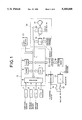
- FIG. 1 presents a block diagram of an on-vehicle navigation apparatus according to one embodiment of the present invention.
- a direction sensor 1 detects the running direction of a vehicle
- an angular velocity sensor 2 detects an angular velocity of the vehicle
- a distance sensor 3 detects the traveling distance of the vehicle
- a GPS (Global Positioning System) device 4 detects the absolute location of the vehicle on the basis of latitude and longitude information and the like. Detected outputs from these sensors and device are supplied to a system controller 5.
- Used as the direction sensor 1 is, for example, a geomagnetic sensor which detects the running direction of the vehicle by geomagnetism (i.e., with respect to the Earth's geomagnetic field).
- the distance sensor 3 comprises a pulse generator which generates a pulse every rotation of a predetermined angle of the drive shaft (not shown) of the vehicle.
- the pulse generator is of a known type which magnetically or optically detects the rotational angle and position of the drive shaft.
- a CD-ROM is used as an external storage medium and is a nonvolatile read only storage medium.
- the external storage medium is not limited to a CD-ROM, but may be a different nonvolatile storage medium, such as a DAT or an IC card.
- Map data is acquired by digitization of individual points on roads of maps and is previously stored in the CD-ROM.
- the information in the CD-ROM is read out through a CD-ROM drive 10.
- the read information from the CD-ROM drive is decoded by a CD-ROM decoder 11 to be sent on a bus line L.
- a source voltage from the battery through a so-called accessory switch 12 of the vehicle is regulated by a regulator 13 and supplied as a power source to the individual sections of the navigation apparatus.
- the voltage to be supplied to the RAM 9 does not come through the accessory switch 12 and is regulated by another regulator (not shown) different from the regulator 13.
- a detector 15 which detects the ON state of a starter switch 14 in order to detect the start of the engine of the vehicle.
- the detector 15 is connected to the output side of the starter switch 14, so that it may detect the level of a voltage supplied to a starter motor (not shown) when the starter switch 14 is turned on. In other words, when the level of the voltage supplied to the starter motor rises to or above a predetermined level, the detector 15 generates a start detection signal.
- the detection output of the detector 15 is coupled to the CPU 7.
- the CPU 7 executes timer interruption to compute the running direction of the vehicle on the basis of the output data of the direction sensor 1 at a given cycle.
- the CPU 7 also acquires longitude data and latitude data as coordinate data of the present location of the vehicle from the covered distance and direction by the interruption every run of a predetermined distance based on the output data from the distance sensor 3.
- the CPU 7 collects the map data of an area of a certain range including the coordinates of the present location from the CD-ROM, and temporarily stores the data in the RAM 9 as well as supplies it to a display device 16.
- the display device 16 comprises a display 17 such as a CRT, a graphic memory 18 constituted of a V (Video)-RAM or the like, a graphic controller 19, and a display controller 20.
- the graphic controller 19 writes the map data sent from the system controller 5 into the graphic memory 18 as image data and generates the data.
- the display controller 20 performs such control as displaying a map on the display 17 in accordance with the image data generated from the graphic controller 19.
- An input device 21 is constituted of a keyboard or the like and issues various commands and the like to the system controller 5 by the key operation of a user.
- the destination coordinate data writing operation which is executed by the CPU 7 will be described in accordance with the destination setting routine illustrated as a flowchart in FIG. 2.
- the routine is accessed and executed when a setting menu is selected by the key operation of the user through the input device 21 during execution of the main routine (not shown), which includes processes, such that the present location of the vehicle is checked on the basis of individual output data of the sensors 1 and 3, a group of map data of an area of a certain range including the vehicle's present location is read out from the CD-ROM to display it as maps around this present location on the display 17, and a position indicator representing the vehicle's present location is displayed on the maps.
- the computing operation for the distance and direction from the present location to the destination, which is executed by the CPU 7 will be described in accordance with the distance and direction computing routine illustrated as a flowchart in FIG. 3.
- the routine is to be executed as a subroutine in the above-described main routine.
- the CPU 7 calculates the distance and direction from the present location to the destination on the basis of the destination coordinate data and present-location coordinate data (step S14).
- the CPU 7 then supplies data representing the acquired distance and direction to the graphic controller 19 to display the distance and direction on the display 17 (step S15).
- the distance and direction between two points, such as the present location and destination, may be computed by, for example, a method disclosed in Japanese Provisional Patent Publication No. 60-282344.
- the CPU 7 determines if the computed distance D is equal to or smaller than a predetermined value D1 (step S25).
- D ⁇ D1 the CPU 7 erases the destination coordinate data from the RAM 9 because the vehicle has already arrived at the destination through the previous running (step S26). Then the CPU 7 resets the destination memory flag F to "0" (step S27) before terminating the routine.
- D>D1 the CPU 7 will terminate this routine immediately to hold the destination coordinate data in the RAM 9 because the vehicle has not arrived at the destination yet in the previous running. After termination of the data clear routine, the CPU 7 starts executing the main routine.
- the predetermined value D1 When the distance D from the present location to the destination is equal to or smaller than the predetermined value D1 at the time the vehicle's engine is started, therefore, it is considered that the engine has been shut off as the vehicle has arrived at the destination, and that the present start of the engine is for driving toward a new destination, and the destination coordinate data stored in the memory will be erased. Since it is very likely that the engine is temporarily shut off when the vehicle arrives at a destination, there will not be any problem to set the predetermined value D1 sufficiently larger than the threshold value needed to determine whether the vehicle has arrived at the destination during actual driving.
- the start of the engine of a vehicle is not only determined from the level of the voltage supplied to the starter motor, but may also be detected from, for instance, engine parameters such as the number of revolutions of the engine, the temperature of the engine coolant and the amount of the intake air.
Abstract
Description
Claims (5)
Applications Claiming Priority (2)
| Application Number | Priority Date | Filing Date | Title |
|---|---|---|---|
| JP3-079881 | 1991-04-12 | ||
| JP3079881A JP2891793B2 (en) | 1991-04-12 | 1991-04-12 | In-vehicle navigation device |
Publications (1)
| Publication Number | Publication Date |
|---|---|
| US5365448A true US5365448A (en) | 1994-11-15 |
Family
ID=13702589
Family Applications (1)
| Application Number | Title | Priority Date | Filing Date |
|---|---|---|---|
| US07/858,645 Expired - Lifetime US5365448A (en) | 1991-04-12 | 1992-03-27 | On-vehicle navigation apparatus with automatic re-initialization function |
Country Status (4)
| Country | Link |
|---|---|
| US (1) | US5365448A (en) |
| EP (1) | EP0508826B1 (en) |
| JP (1) | JP2891793B2 (en) |
| DE (1) | DE69212037T2 (en) |
Cited By (19)
| Publication number | Priority date | Publication date | Assignee | Title |
|---|---|---|---|---|
| US5793631A (en) * | 1992-08-19 | 1998-08-11 | Aisin Aw Co., Ltd. | Voice route-guidance system and method having a function for judging approachment to a decision point |
| US5922042A (en) * | 1996-09-30 | 1999-07-13 | Visteon Technologies, Llc | Automatic resumption of route guidance in vehicle navigation system |
| US5951620A (en) * | 1996-01-26 | 1999-09-14 | Navigation Technologies Corporation | System and method for distributing information for storage media |
| US6067500A (en) * | 1995-08-14 | 2000-05-23 | Aisin Aw Co., Ltd. | Navigation system |
| US6687615B1 (en) * | 2001-12-21 | 2004-02-03 | Garmin Ltd. | Navigation system, method and device with detour algorithm |
| US20040088109A1 (en) * | 2001-01-31 | 2004-05-06 | Jun Miyashita | Route searching device |
| US20050137793A1 (en) * | 2001-12-21 | 2005-06-23 | Garmin Ltd., A Cayman Islands Corporation | Navigation system, method and device with detour algorithm |
| US7184886B1 (en) | 2001-12-21 | 2007-02-27 | Garmin Ltd. | Navigation system, method and device with detour algorithm |
| US7206692B2 (en) | 2001-12-11 | 2007-04-17 | Garmin Ltd. | System and method for estimating impedance time through a road network |
| US7269508B1 (en) | 2001-12-21 | 2007-09-11 | Garmin Ltd. | Guidance with feature accounting for insignificant roads |
| US7277794B1 (en) | 2001-12-21 | 2007-10-02 | Garmin Ltd. | Guidance with feature accounting for insignificant roads |
| US7283905B1 (en) | 2001-12-11 | 2007-10-16 | Garmin Ltd. | System and method for estimating impedance time through a road network |
| US7308359B1 (en) | 2001-12-21 | 2007-12-11 | Garmin Ltd. | Navigation system, method and device with automatic next turn page |
| US7409288B1 (en) | 2001-12-20 | 2008-08-05 | Garmin Ltd. | Portable navigation system and device with audible turn instructions |
| US7908080B2 (en) | 2004-12-31 | 2011-03-15 | Google Inc. | Transportation routing |
| US7925320B2 (en) | 2006-03-06 | 2011-04-12 | Garmin Switzerland Gmbh | Electronic device mount |
| US20140163881A1 (en) * | 2012-12-06 | 2014-06-12 | Harman Becker Automotive Systems Gmbh | Control of an external drivebox |
| US10986165B2 (en) | 2004-01-13 | 2021-04-20 | May Patents Ltd. | Information device |
| US20210256502A1 (en) * | 2020-01-14 | 2021-08-19 | Capital One Services, Llc | Account entity location based navigation and display for a projectable transaction card |
Families Citing this family (3)
| Publication number | Priority date | Publication date | Assignee | Title |
|---|---|---|---|---|
| JP4084901B2 (en) * | 1999-03-05 | 2008-04-30 | 株式会社日立製作所 | Information provision system |
| DE10146244A1 (en) * | 2001-09-20 | 2003-04-30 | Bosch Gmbh Robert | Navigation system and method for starting control of a navigation system |
| JP4635833B2 (en) * | 2005-11-09 | 2011-02-23 | 株式会社デンソー | Car navigation system |
Citations (11)
| Publication number | Priority date | Publication date | Assignee | Title |
|---|---|---|---|---|
| US4053749A (en) * | 1975-05-15 | 1977-10-11 | Nippon Soken, Inc. | Distance meter for vehicle capable of displaying travelling distance to destination |
| US4382178A (en) * | 1979-03-09 | 1983-05-03 | Nissan Motor Company, Limited | Electronic trip meter for an automotive vehicle |
| US4403291A (en) * | 1979-10-11 | 1983-09-06 | Siemens Aktiengesellschaft | Self-sufficient navigation device for street vehicles |
| JPS62140013A (en) * | 1985-12-16 | 1987-06-23 | Mazda Motor Corp | Apparatus for correcting earth magnetism sensor |
| JPS6312096A (en) * | 1986-07-02 | 1988-01-19 | パイオニア株式会社 | Recognition of current location for vehicle |
| JPS63115004A (en) * | 1986-10-31 | 1988-05-19 | Pioneer Electronic Corp | Present place estimating method for vehicle |
| US5031104A (en) * | 1988-12-05 | 1991-07-09 | Sumitomo Electric Industries, Ltd. | Adaptive in-vehicle route guidance system |
| US5067081A (en) * | 1989-08-30 | 1991-11-19 | Person Carl E | Portable electronic navigation aid |
| US5093669A (en) * | 1989-10-20 | 1992-03-03 | Mazda Motor Corporation | Vehicle navigation apparatus |
| US5142207A (en) * | 1989-05-19 | 1992-08-25 | Samsung Electronics Co., Ltd. | Acceleration and deceleration method for transferring device |
| US5268844A (en) * | 1989-03-06 | 1993-12-07 | Carver Christopher S | Electronic digital position and navigational plotter |
-
1991
- 1991-04-12 JP JP3079881A patent/JP2891793B2/en not_active Expired - Lifetime
-
1992
- 1992-03-27 US US07/858,645 patent/US5365448A/en not_active Expired - Lifetime
- 1992-04-10 DE DE69212037T patent/DE69212037T2/en not_active Expired - Lifetime
- 1992-04-10 EP EP92303255A patent/EP0508826B1/en not_active Expired - Lifetime
Patent Citations (11)
| Publication number | Priority date | Publication date | Assignee | Title |
|---|---|---|---|---|
| US4053749A (en) * | 1975-05-15 | 1977-10-11 | Nippon Soken, Inc. | Distance meter for vehicle capable of displaying travelling distance to destination |
| US4382178A (en) * | 1979-03-09 | 1983-05-03 | Nissan Motor Company, Limited | Electronic trip meter for an automotive vehicle |
| US4403291A (en) * | 1979-10-11 | 1983-09-06 | Siemens Aktiengesellschaft | Self-sufficient navigation device for street vehicles |
| JPS62140013A (en) * | 1985-12-16 | 1987-06-23 | Mazda Motor Corp | Apparatus for correcting earth magnetism sensor |
| JPS6312096A (en) * | 1986-07-02 | 1988-01-19 | パイオニア株式会社 | Recognition of current location for vehicle |
| JPS63115004A (en) * | 1986-10-31 | 1988-05-19 | Pioneer Electronic Corp | Present place estimating method for vehicle |
| US5031104A (en) * | 1988-12-05 | 1991-07-09 | Sumitomo Electric Industries, Ltd. | Adaptive in-vehicle route guidance system |
| US5268844A (en) * | 1989-03-06 | 1993-12-07 | Carver Christopher S | Electronic digital position and navigational plotter |
| US5142207A (en) * | 1989-05-19 | 1992-08-25 | Samsung Electronics Co., Ltd. | Acceleration and deceleration method for transferring device |
| US5067081A (en) * | 1989-08-30 | 1991-11-19 | Person Carl E | Portable electronic navigation aid |
| US5093669A (en) * | 1989-10-20 | 1992-03-03 | Mazda Motor Corporation | Vehicle navigation apparatus |
Cited By (36)
| Publication number | Priority date | Publication date | Assignee | Title |
|---|---|---|---|---|
| US5793631A (en) * | 1992-08-19 | 1998-08-11 | Aisin Aw Co., Ltd. | Voice route-guidance system and method having a function for judging approachment to a decision point |
| US6067500A (en) * | 1995-08-14 | 2000-05-23 | Aisin Aw Co., Ltd. | Navigation system |
| US5951620A (en) * | 1996-01-26 | 1999-09-14 | Navigation Technologies Corporation | System and method for distributing information for storage media |
| US6018695A (en) * | 1996-01-26 | 2000-01-25 | Navigation Technologies Corporation | System and method for distributing information for storage media |
| US6131066A (en) * | 1996-01-26 | 2000-10-10 | Navigation Technologies Corp. | System and method for distributing information for storage media |
| US6289276B1 (en) | 1996-01-26 | 2001-09-11 | Navigation Technologies Corporation | System and method for distributing information for storage media |
| US5922042A (en) * | 1996-09-30 | 1999-07-13 | Visteon Technologies, Llc | Automatic resumption of route guidance in vehicle navigation system |
| US7546203B2 (en) * | 2001-01-31 | 2009-06-09 | Xanavi Informatics Corporation | Route searching device |
| US20040088109A1 (en) * | 2001-01-31 | 2004-05-06 | Jun Miyashita | Route searching device |
| US7206692B2 (en) | 2001-12-11 | 2007-04-17 | Garmin Ltd. | System and method for estimating impedance time through a road network |
| US7283905B1 (en) | 2001-12-11 | 2007-10-16 | Garmin Ltd. | System and method for estimating impedance time through a road network |
| US7409288B1 (en) | 2001-12-20 | 2008-08-05 | Garmin Ltd. | Portable navigation system and device with audible turn instructions |
| US20050137793A1 (en) * | 2001-12-21 | 2005-06-23 | Garmin Ltd., A Cayman Islands Corporation | Navigation system, method and device with detour algorithm |
| US7184886B1 (en) | 2001-12-21 | 2007-02-27 | Garmin Ltd. | Navigation system, method and device with detour algorithm |
| US7269508B1 (en) | 2001-12-21 | 2007-09-11 | Garmin Ltd. | Guidance with feature accounting for insignificant roads |
| US7277794B1 (en) | 2001-12-21 | 2007-10-02 | Garmin Ltd. | Guidance with feature accounting for insignificant roads |
| US7120539B2 (en) | 2001-12-21 | 2006-10-10 | Garmin Ltd. | Navigation system, method and device with detour algorithm |
| US7308359B1 (en) | 2001-12-21 | 2007-12-11 | Garmin Ltd. | Navigation system, method and device with automatic next turn page |
| US6999873B1 (en) | 2001-12-21 | 2006-02-14 | Garmin Ltd. | Navigation system, method and device with detour algorithm |
| US6687615B1 (en) * | 2001-12-21 | 2004-02-03 | Garmin Ltd. | Navigation system, method and device with detour algorithm |
| US11095708B2 (en) | 2004-01-13 | 2021-08-17 | May Patents Ltd. | Information device |
| US11032353B2 (en) | 2004-01-13 | 2021-06-08 | May Patents Ltd. | Information device |
| US10986164B2 (en) | 2004-01-13 | 2021-04-20 | May Patents Ltd. | Information device |
| US10986165B2 (en) | 2004-01-13 | 2021-04-20 | May Patents Ltd. | Information device |
| US9945686B2 (en) | 2004-12-31 | 2018-04-17 | Google Llc | Transportation routing |
| US9709415B2 (en) | 2004-12-31 | 2017-07-18 | Google Inc. | Transportation routing |
| US9778055B2 (en) | 2004-12-31 | 2017-10-03 | Google Inc. | Transportation routing |
| US8798917B2 (en) | 2004-12-31 | 2014-08-05 | Google Inc. | Transportation routing |
| US8606514B2 (en) | 2004-12-31 | 2013-12-10 | Google Inc. | Transportation routing |
| US7908080B2 (en) | 2004-12-31 | 2011-03-15 | Google Inc. | Transportation routing |
| US11092455B2 (en) | 2004-12-31 | 2021-08-17 | Google Llc | Transportation routing |
| US7925320B2 (en) | 2006-03-06 | 2011-04-12 | Garmin Switzerland Gmbh | Electronic device mount |
| US9335177B2 (en) * | 2012-12-06 | 2016-05-10 | Harman Becker Automotive Systems Gmbh | Control of an external drivebox |
| US20140163881A1 (en) * | 2012-12-06 | 2014-06-12 | Harman Becker Automotive Systems Gmbh | Control of an external drivebox |
| US20210256502A1 (en) * | 2020-01-14 | 2021-08-19 | Capital One Services, Llc | Account entity location based navigation and display for a projectable transaction card |
| US11854001B2 (en) * | 2020-01-14 | 2023-12-26 | Capital One Services, Llc | Account entity location based navigation and display for a projectable transaction card |
Also Published As
| Publication number | Publication date |
|---|---|
| DE69212037D1 (en) | 1996-08-14 |
| EP0508826B1 (en) | 1996-07-10 |
| JPH04314081A (en) | 1992-11-05 |
| DE69212037T2 (en) | 1997-01-23 |
| EP0508826A3 (en) | 1993-05-05 |
| JP2891793B2 (en) | 1999-05-17 |
| EP0508826A2 (en) | 1992-10-14 |
Similar Documents
| Publication | Publication Date | Title |
|---|---|---|
| US5365448A (en) | On-vehicle navigation apparatus with automatic re-initialization function | |
| US5337244A (en) | On-board navigation apparatus | |
| US6762772B1 (en) | Information display apparatus and navigation apparatus | |
| US5922042A (en) | Automatic resumption of route guidance in vehicle navigation system | |
| US4903211A (en) | On-board navigation system for motor vehicles | |
| JPH05157572A (en) | Navigation system | |
| JP4530013B2 (en) | Car navigation system and program | |
| US5828321A (en) | Location detecting system | |
| JP3140130B2 (en) | Navigation device | |
| KR100196725B1 (en) | Map matching method for car navigation system using gps | |
| JPH06147908A (en) | Navigation device | |
| JP2006293789A (en) | On-vehicle information processor | |
| JP2910515B2 (en) | Navigation device and navigation method | |
| JP2008070151A (en) | Current position displaying device, navigation apparatus, and program | |
| JPH04250313A (en) | Travel distance calculating device for vehicle | |
| JP3203732B2 (en) | Map display device | |
| JP3402105B2 (en) | Positioning device | |
| JPH04315914A (en) | Vehicle running distance calculating device | |
| JPS58151512A (en) | Running position display for vehicle | |
| JPH09159468A (en) | Display device for running position | |
| KR20000039342A (en) | Method for correcting road data in navigation system | |
| JP2814242B2 (en) | In-vehicle navigation device | |
| JPH10318765A (en) | Vehicle-mounted navigation device | |
| JP2003288751A (en) | Navigation system for automobile | |
| KR100247979B1 (en) | Trace display method of navigation |
Legal Events
| Date | Code | Title | Description |
|---|---|---|---|
| AS | Assignment |
Owner name: PIONEER ELECTRONIC CORPORATION, JAPAN Free format text: ASSIGNMENT OF ASSIGNORS INTEREST.;ASSIGNORS:NOBE, KENICHI;ARAKI, MORIO;REEL/FRAME:006069/0754 Effective date: 19920316 |
|
| STCF | Information on status: patent grant |
Free format text: PATENTED CASE |
|
| FEPP | Fee payment procedure |
Free format text: PAYOR NUMBER ASSIGNED (ORIGINAL EVENT CODE: ASPN); ENTITY STATUS OF PATENT OWNER: LARGE ENTITY |
|
| FPAY | Fee payment |
Year of fee payment: 4 |
|
| SULP | Surcharge for late payment | ||
| FPAY | Fee payment |
Year of fee payment: 8 |
|
| REMI | Maintenance fee reminder mailed | ||
| FEPP | Fee payment procedure |
Free format text: PAYOR NUMBER ASSIGNED (ORIGINAL EVENT CODE: ASPN); ENTITY STATUS OF PATENT OWNER: LARGE ENTITY Free format text: PAYER NUMBER DE-ASSIGNED (ORIGINAL EVENT CODE: RMPN); ENTITY STATUS OF PATENT OWNER: LARGE ENTITY |
|
| FPAY | Fee payment |
Year of fee payment: 12 |
|
| AS | Assignment |
Owner name: PIONEER CORPORATION, JAPAN Free format text: CHANGE OF NAME;ASSIGNOR:PIONEER ELECTRONIC CORPORATION;REEL/FRAME:023486/0177 Effective date: 19990629 |