US5371506A - Simultaneous multibeam approach for cancelling multiple mainlobe jammers while preserving monopulse angle estimation accuracy on mainlobe targets - Google Patents
Simultaneous multibeam approach for cancelling multiple mainlobe jammers while preserving monopulse angle estimation accuracy on mainlobe targets Download PDFInfo
- Publication number
- US5371506A US5371506A US08/093,167 US9316793A US5371506A US 5371506 A US5371506 A US 5371506A US 9316793 A US9316793 A US 9316793A US 5371506 A US5371506 A US 5371506A
- Authority
- US
- United States
- Prior art keywords
- sub
- mainlobe
- elevation
- azimuth
- signals
- Prior art date
- Legal status (The legal status is an assumption and is not a legal conclusion. Google has not performed a legal analysis and makes no representation as to the accuracy of the status listed.)
- Expired - Lifetime
Links
- 238000013459 approach Methods 0.000 title description 5
- 238000000034 method Methods 0.000 claims description 53
- 230000003044 adaptive effect Effects 0.000 claims description 52
- 238000012545 processing Methods 0.000 claims description 23
- 230000004044 response Effects 0.000 claims description 11
- 238000007781 pre-processing Methods 0.000 claims description 5
- 238000001914 filtration Methods 0.000 claims 1
- 238000005259 measurement Methods 0.000 abstract description 13
- 230000006872 improvement Effects 0.000 abstract description 2
- 230000006978 adaptation Effects 0.000 description 22
- 239000011159 matrix material Substances 0.000 description 21
- 238000010586 diagram Methods 0.000 description 14
- 239000013598 vector Substances 0.000 description 9
- 238000001514 detection method Methods 0.000 description 8
- 238000003491 array Methods 0.000 description 7
- 230000014509 gene expression Effects 0.000 description 5
- 230000035945 sensitivity Effects 0.000 description 5
- 230000005540 biological transmission Effects 0.000 description 4
- 230000000694 effects Effects 0.000 description 4
- 238000012423 maintenance Methods 0.000 description 4
- 238000007476 Maximum Likelihood Methods 0.000 description 3
- 238000004458 analytical method Methods 0.000 description 3
- 230000001427 coherent effect Effects 0.000 description 3
- 230000000875 corresponding effect Effects 0.000 description 3
- 238000012986 modification Methods 0.000 description 3
- 230000004048 modification Effects 0.000 description 3
- 230000002238 attenuated effect Effects 0.000 description 2
- 230000008901 benefit Effects 0.000 description 2
- 230000000903 blocking effect Effects 0.000 description 2
- 238000004422 calculation algorithm Methods 0.000 description 2
- 238000005094 computer simulation Methods 0.000 description 2
- 238000009795 derivation Methods 0.000 description 2
- 238000011161 development Methods 0.000 description 2
- 238000005516 engineering process Methods 0.000 description 2
- FDKXTQMXEQVLRF-ZHACJKMWSA-N (E)-dacarbazine Chemical compound CN(C)\N=N\c1[nH]cnc1C(N)=O FDKXTQMXEQVLRF-ZHACJKMWSA-N 0.000 description 1
- 238000012935 Averaging Methods 0.000 description 1
- 238000004891 communication Methods 0.000 description 1
- 239000012141 concentrate Substances 0.000 description 1
- 230000001276 controlling effect Effects 0.000 description 1
- 230000002596 correlated effect Effects 0.000 description 1
- 238000000354 decomposition reaction Methods 0.000 description 1
- 238000013461 design Methods 0.000 description 1
- 230000006870 function Effects 0.000 description 1
- 238000005286 illumination Methods 0.000 description 1
- 230000008450 motivation Effects 0.000 description 1
- 230000008569 process Effects 0.000 description 1
- 238000011160 research Methods 0.000 description 1
- 238000012360 testing method Methods 0.000 description 1
Images


Classifications
-
- G—PHYSICS
- G01—MEASURING; TESTING
- G01S—RADIO DIRECTION-FINDING; RADIO NAVIGATION; DETERMINING DISTANCE OR VELOCITY BY USE OF RADIO WAVES; LOCATING OR PRESENCE-DETECTING BY USE OF THE REFLECTION OR RERADIATION OF RADIO WAVES; ANALOGOUS ARRANGEMENTS USING OTHER WAVES
- G01S13/00—Systems using the reflection or reradiation of radio waves, e.g. radar systems; Analogous systems using reflection or reradiation of waves whose nature or wavelength is irrelevant or unspecified
- G01S13/02—Systems using reflection of radio waves, e.g. primary radar systems; Analogous systems
- G01S13/06—Systems determining position data of a target
- G01S13/42—Simultaneous measurement of distance and other co-ordinates
- G01S13/44—Monopulse radar, i.e. simultaneous lobing
- G01S13/4463—Monopulse radar, i.e. simultaneous lobing using phased arrays
-
- G—PHYSICS
- G01—MEASURING; TESTING
- G01S—RADIO DIRECTION-FINDING; RADIO NAVIGATION; DETERMINING DISTANCE OR VELOCITY BY USE OF RADIO WAVES; LOCATING OR PRESENCE-DETECTING BY USE OF THE REFLECTION OR RERADIATION OF RADIO WAVES; ANALOGOUS ARRANGEMENTS USING OTHER WAVES
- G01S7/00—Details of systems according to groups G01S13/00, G01S15/00, G01S17/00
- G01S7/02—Details of systems according to groups G01S13/00, G01S15/00, G01S17/00 of systems according to group G01S13/00
- G01S7/36—Means for anti-jamming, e.g. ECCM, i.e. electronic counter-counter measures
-
- H—ELECTRICITY
- H01—ELECTRIC ELEMENTS
- H01Q—ANTENNAS, i.e. RADIO AERIALS
- H01Q25/00—Antennas or antenna systems providing at least two radiating patterns
- H01Q25/02—Antennas or antenna systems providing at least two radiating patterns providing sum and difference patterns
-
- H—ELECTRICITY
- H01—ELECTRIC ELEMENTS
- H01Q—ANTENNAS, i.e. RADIO AERIALS
- H01Q3/00—Arrangements for changing or varying the orientation or the shape of the directional pattern of the waves radiated from an antenna or antenna system
- H01Q3/26—Arrangements for changing or varying the orientation or the shape of the directional pattern of the waves radiated from an antenna or antenna system varying the relative phase or relative amplitude of energisation between two or more active radiating elements; varying the distribution of energy across a radiating aperture
- H01Q3/2605—Array of radiating elements provided with a feedback control over the element weights, e.g. adaptive arrays
- H01Q3/2611—Means for null steering; Adaptive interference nulling
Definitions
- This invention generally relates to radar techniques for determining angular location of a target and, more particularly, to an improvement in the monopulse technique so as to maintain accuracy of the monopulse ratio in the presence of simultaneous jamming from multiple mainlobe jammers.
- the monopulse technique is a radar technique in which the angular location of a target can be determined within fractions of a beamwidth by comparing measurements received by two or more simultaneous beams.
- This technique for direction of arrival (DOA) estimation of a target is widely employed in modern surveillance and tracking radar. See, for example, D. K. Barton, "Modern Radar Systems Analysis", Artech House (1988), M. Sherman, “Monopulse Principles and Techniques", Artech House (1984),and I. Leanov and K. I. Fomichev, "Monopulse Radar", Artech House (1986).
- DBF digital beamforming
- the monopulse technique may be implemented for a linear array of N antenna elements which provide respective signals x(0), . . . , x(N-1) to the beam forming network from the elemental receivers.
- the output signals of the beam forming network are the sum, ⁇ , and difference, ⁇ , signals which are processed in a processor to generate an output signal, ⁇ , representing the direction of arrival estimation.
- each of the N input signals is split into two paths, linearly weighted, and then added together.
- the sum ⁇ and difference ⁇ signals may be expressed in the form
- W.sub. ⁇ is real and even weighting
- W.sub. ⁇ is purely imaginary and odd weighting
- H indicates the complex conjugate transpose
- x is the vector of the measurements.
- Taylor and Bayliss weightings are typically used for sum beams and difference beams, respectively, so as to have a narrow mainlobe and low sidelobes. In the presence of jamming, the weights are adapted so as to form nulls responsive to the jammers.
- the quiescent Taylor and Bayliss weightings are designed for reducing the sidelobes in a practical system. See Y. T. Lo and S. W. Lee, "Antenna Handbook," Theory, Applications and Design, Van Nostrand Reinhold Company, New York (1988), Chapter 13.
- the mainlobe of the pattern is a central beam surrounded by minor lobes, commonly referred to as sidelobes.
- minor lobes commonly referred to as sidelobes.
- sidelobe levels of an antenna pattern can be described in several ways. The most common expression is the relative sidelobe level, defined as the peak level of the highest sidelobe relative to the peak level of the main beam. Sidelobe levels can also be quantified in terms of their absolute level relative to isotropic.
- the term "monopulse” refers to the fact that the echo from a single transmitter pulse returning from a target is used to measure the angle of the target, and typically, one beam (instead of two beams) is formed in transmission, and two beams are formed on reception for angle measurement.
- the sum beam has a symmetrical amplitude profile with its maximum at the boresight, and the difference beam has an antisymmetrical amplitude profile with zero response at the boresight.
- the DOA of a target signal can be determined accurately through a look-up table by evaluating the monopulse ratio, i.e., the real part of ⁇ / ⁇ .
- the development of the DOA maximum likelihood estimator also leads naturally to monopulse processing using sum and difference beams. See R. C. David, L. E. Brennan, and I. S. Reed, "Angle Estimation with Adaptive Arrays in External Noise Field," IEEE Trans. on Aerospace and Electronic Systems, Vol. AES-12, No. 2, March 1976.
- the estimator is unbiased with mean square error (MSE) given by ##EQU2## which is known to be the monopulse sensitivity factor, f, is the monopulse function and f is the derivative of f.
- MSE mean square error
- SNR is the signal-to-noise ratio at the elemental level
- g(T) is the two-way sum beam antenna pattern.
- the monopulse sensitivity factor is defined as the constant of proportionality required in the denominator of the root-mean-square-error (RMSE) to convert the square root of twice the boresight signal-to-noise ratio in the beam to RMSE.
- RMSE root-mean-square-error
- the monopulse sensitivity factor has the desirable property of containing all target angle-of-arrival information. See D. J. Murrow, "Height Finding and 3D Radar," Chapter 20, Radar Handbook (2nd Edition), McGraw-Hill.
- This technique can also be considered for a planar array where the target azimuth and elevation angles are desired.
- a set of sum ( ⁇ e ) and difference ( ⁇ e ) beams are formed along the elevation axis with input signals from each column of sensors.
- Monopulse ratios along azimuth or elevation direction can then be formed giving the azimuth and elevation DOA estimates by using the following equations: ##EQU3##
- the monopulse technique for DOA estimation fails when there is sidelobe jamming (SLJ) and/or mainlobe jamming (MLJ). If not effectively countered, electronic jamming prevents successful radar target detection and tracking. The situation is exacerbated by introduction of stealth technology to reduce the radar cross section (RCS) of unfriendly aircraft targets.
- RCS radar cross section
- the frequency dependence of the RCS encourages the use of lower microwave frequency bands for detection. This leads to large apertures to achieve angular resolution. Large apertures to achieve small beamwidth result in interception of more jamming. On the other hand, constrained apertures lead to wider beamwidth, which implies interception of more mainlobe jamming.
- This invention is a technique which cancels multiple mainlobe jammers while preserving detection and monopulse accuracy performance on mainlobe targets.
- the additional degrees of freedom for cancelling more than one MLJ are achieved by using multiple simultaneous beams.
- the beams are placed one null beamwidth apart in order to maintain orthogonality.
- the MLJs are nulled in the orthogonal direction of the angle estimate, giving an undistorted monopulse ratio.
- FIG. 1 is a block diagram showing a monopulse beamforming network for estimating direction of arrival
- FIG. 2 is a detailed diagram of a beamforming network
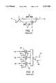
- FIG. 3 is a perspective view of a monopulse radar antenna pattern
- FIG. 4 is a graph of sum and difference beam patterns for monopulse antennas
- FIG. 5 is a graph of the monpulse ratio
- FIG. 6 is a block diagram of a monopulse radar
- FIG. 7 is a block diagram showing a sum-difference mainlobe canceler
- FIG. 8 is a block diagram showing a mainlobe canceler for monopulse processing
- FIG. 9 is a block diagram showing an adaptive array for forming sum and difference beam output signals
- FIG. 10 is a schematic diagram showing a multiple sidelobe canceler for sum and difference channels
- FIG. 11 is a pair of graphs showing sidelobe jammer nulling
- FIG. 12 is a diagram showing the Howells-Applebaum feedback loop
- FIG. 13 is a block diagram of the architecture for cascading a multiple sidelobe canceler with mainlobe canceler for monopulse processing
- FIG. 13A is a block diagram of a modification of the mainlobe/multiple sidelobe canceler shown in FIG. 13;
- FIG. 14 is a diagram showing mainlobe maintenance in conjunction with a multiple sidelobe canceler
- FIG. 15 is a block diagram of the architecture for combining an adaptive array with a mainlobe canceler for monopulse processing
- FIG. 16 is a diagram of a beamforming front end for processing three simultaneous received beams into eight simultaneous reception beams in accordance with the invention.
- FIG. 17 is a block diagram of a canceller for two mainlobe jammers in accordance with the invention.
- FIG. 18 is a graph showing an adapted sum azimuth beam pattern for a jamming scenario in accordance with the invention.
- FIG. 19 is a graph showing an adapted difference azimuth beam pattern for a jamming scenario in accordance with the invention.
- FIG. 20 is a graph of azimuth monopulse ratio for a jamming scenario in accordance with the invention.
- FIG. 21 is a graph showing an adapted sum elevation beam pattern for a jamming scenario in accordance with the invention.
- FIG. 22 is a graph showing an adapted difference elevation beam pattern for a jamming scenario in accordance with the invention.
- FIG. 23 is a graph of the elevation monopulse ratio for a jamming scenario in accordance with the invention.
- the monopulse technique for DOA estimation is implemented for a linear array of antenna elements 10 0 to 10 N-1 which provide respective signals x(0), . . . , x(N-1), shown in FIG. 1, to the beam forming (BF) network 12 for combining the input signals from the elemental receiver.
- the output signals of the BF network 12 are the sum ⁇ and difference ⁇ signals which are processed in a processor 14 to generate an output signal ⁇ representing the direction of arrival estimation.
- Beamforming network 12 is more fully described in FIG. 2 and comprises voltage splitters 1, weighting network 22 and adders 23. Each of the N input signals is split into two paths which are linearly weighted, and in each of the two paths the N signals are added together.
- Taylor and Bayliss weightings are typically used for sum beams and difference beams, respectively, so as to have a narrow mainlobe and low sidelobes. In the presence of jamming the weights are adapted so as to form nulls responsive to the jammers.
- the quiescent Taylor and Bayliss weightings are designed for reducing the sidelobes in a practical system.
- FIG. 3 represents a typical sum beam antenna pattern.
- the mainlobe of the pattern is a central beam 31 surrounded by minor lobes 32, or sidelobes.
- minor lobes 32 or sidelobes.
- the monopulse technique typically one beam (instead of two beams) is formed in transmission, and two beams are formed on reception for angle measurement.
- the sum beam 41 antenna pattern has a symmetrical amplitude profile with its maximum at the boresight
- the difference beam 42 antenna pattern has an antisymmetrical amplitude profile with zero response at the boresight.
- the DOA of a target signal can be determined accurately through a look-up table by evaluating the monopulse ratio 51, i.e., the real part of ⁇ /93 , as shown in FIG. 5.
- the DOA maximum likelihood estimator is unbiased with mean square error (MSE) given by equation (10) as ##EQU5## is the monopulse sensitivity factor, which contains all target angle-of-arrival information.
- This technique can also be used with a planar array where the target azimuth and elevation angles are desired, as shown in FIG. 6.
- a set of sum ( ⁇ c ) and difference ( ⁇ e ) beams are formed along the elevation axis with in put signals from each column of sensors 66 by respective column beamformers 65.
- Monopulse ratios along azimuth or elevation direction can then be formed giving the azimuth and elevation DOA estimates by using equations (5) and (6), which take advantage of the separable property of the planar array patterns.
- the present invention concerns cancellation of multiple mainlobe jammers in such a way that provides target detection and enables unbiased monopulse angle measurement.
- MSLC multiple sidelobe canceler
- MLC sum-difference mainlobe canceler
- P. Applebaum and R. Wasiewicz "Main Beam Jammer Cancellation for Monopulse Sensors", Final Tech.
- MSLC Multiple Sidelobe Canceler
- the sidelobe canceler was actually the first type of adaptive array system to be deployed. It is used to reduce clutter and interference in radar systems and comprises a single high-gain antenna to which a number of small auxiliary elements are added. Both sum ( ⁇ ) and difference ( ⁇ ) channels are required for monopulse processing, as illustrated in FIG. 10.
- the high gain antenna 101 is a typical radar antenna with a narrow beamwidth.
- the auxiliary elements 102 are small, low-gain, and have much wider beamwidths than the high-gain antenna.
- the auxiliary element output signals are multiplied by adaptive weight signals 104 at a weighting network or multiplier 103, combined by an adder 106, and then added to the high-gain antenna output by a summer 105.
- the weights on the auxiliary elements By controlling the weights on the auxiliary elements adaptively, jamming in the sidelobes of the high-gain antenna can be nulled out, as illustrated in FIG. 11.
- This can be achieved by analog or digital circuitry.
- the weights are adjusted using the so-called Howells-Applebaum feedback loop as illustrated in FIG. 12. This This implementation requires a feedback loop for each weight and the weight is controlled by the input signal x j (t) and the error signal at multiplier input 122. The weights will converge to the optimal weight and the jammer is thereby nulled.
- digital samples r.sub. ⁇ (k) for the main array r a (k) and the auxiliary array are measured.
- Cross correlation samples between the main beam and the auxiliary array elements, as well as the auto correlation of the auxiliary elements are estimated using the samples given by ##EQU6##
- the adaptive weights for cancelling the jammers are given by
- weights are then downloaded to the weighting network 123 for combining the auxiliary elements.
- the target signal can be cancelled 1) whenever the signal enters the auxiliary elements, 2) the signal information is inaccurate, or 3) there is correlation between the desired signal and the interference signal.
- Constrained adaptation of the auxiliary array can e employed to prevent cancellation of the target signal.
- Robust methods have been employed to mitigate the effect of inaccurate signal knowledge in the adaptation process (see K. Jablon, "Steady State Analysis of the Generalized Sidelobe Canceler by Adaptive Noise Canceling Techniques," IEEE Trans. On Antennas and Propagation, Vol. AP-34, pp. 330-337, Mar. 1986 and Cox, R. M. Zeskind, and M. M. Owen, "Robust Adaptive Beamforming,” IEEE Trans. On Acoustics, Speech and Signal Processing, Vol.
- the array elements do not have enough gain to cancel the mainlobe jammer (MLJ). Also, noise enters the system if the gain of the auxiliary array is increased.
- the sum-difference mainlobe canceler is shown in FIG. 7.
- a single antenna 70 is used to generate the sum ( ⁇ ) and difference ( ⁇ ) signals.
- the high mainlobe gain of the difference beam can be used to null the mainlobe jammer in the sum beam.
- the difference beam has a high gain and thus can be used for cancelling the mainlobe jammer without introducing excessive noise in the main antenna.
- T j is the direction cosine of the jammer.
- the optimal weight for cancelling the jammer is given by ##EQU7##
- Equation 14 is a very good approximation for large jammer-to-noise ratio.
- the canceler weight W is actually given by the ratio of the cross-correlation between the sum and difference beam output signals to the auto-correlation of the difference beam output signals, and is approximated by equation (14) for large jammer-to-noise ratio (JNR). Since ⁇ and ⁇ beams have comparable gain within the mainbeam, weight W would be a moderate number. If low gain auxiliary elements are used for mainlobe jamming cancellation, large weights are required for cancelling the jammer in the mainbeam, thus introducing high levels of noise into the system.
- the MLC architecture is shown in FIG. 8.
- the ⁇ and ⁇ E beams can be adapted by the ⁇ A and ⁇ .sub. ⁇ beams are follows:
- w a1 and w a2 are adaptation weights determined as set forth, infra.
- the adaptation of Equation (15) is implemented with multiplier 81 and summer 80.
- Multiplier 81 receives as input signals adaptation weight w a1 and the ⁇ A beam, the and the product is summed in summer 80 with the ⁇ beam.
- the adaptation of Equation (16) is implemented with multiplier 83 and summer 82.
- Multiplier 83 receives as inputs adaptation weight w a2 and the ⁇ .sub. ⁇ beam, and the product is summed in summer 82 and the ⁇ E beam.
- the output signals of summers 80 and 82 i.e., ⁇ ' and ⁇ ' E , are supplied to a processor 84 which generates the elevation monopulse ratio ⁇ ' E / ⁇ '.
- w a1 should be equal to w a2 analytically.
- w a1 may not be equal to w a2 , as the weights are determined by data samples. In that case, we may force them to be equal (e.g., adapt w a in the ⁇ channel and use it in the ⁇ channel or vice versa, or set ##EQU10## i.e., choose the weight to be the average of the adpated weights).
- the monopulse ratio for the elevation angle estimation f e ( ⁇ e ), and f e is the ratio of the adapted difference-elevation beam output signal to the adapted sum beam output signal, is obtained in processor 84 in the following manner: ##EQU11##
- the monopulse ratio along the elevation direction is maintained (except at the azimuth angle where there is a jammer), and the mainlobe jammer is cancelled.
- w e1 and w e2 are adaptation weights determined as set forth, infra.
- the adaptation of Equation (21) is implemented with multiplier 86 and summer 85.
- Multiplier 86 receives as input signals adaptation weight w e1 and the ⁇ E beam, and the product is summed in summer 85 with the ⁇ beam.
- the adaptation of Equation (22) is implemented with multiplier 88 and summer 87.
- Multiplier 88 receives as input signals adaptation weight w e2 and the ⁇ 66 beam, and product is summed in summer 87 with the ⁇ A beam.
- the output signals of summers 85 and 87, i.e., ⁇ ' and ⁇ ' A are supplied to a processor 89 which generates the azimuth monopulse ratio ⁇ ' E / ⁇ '.
- the mainlobe jammer can be cancelled by choosing the following adaptive weights: ##EQU12## Similarly, we can set the weights equal ##EQU13## The monopulse ratio for the azimuth angle ⁇ a estimate can then be shown to be preserved: ##EQU14##
- Adaptive receiving arrays for radar which maximize the signal-to-noise ratio at the array output, were first developed by S. P. Applebaum, see Report SPL-769, supra. These arrays maximize the ratio of antenna gain in a specified scan direction to the total noise in the output signal Similar techniques have been described for communications systems by Widrow et al., supra, which minimize the means square error between the array output and a transmitted pilot signal which is known a priori at the receiver.
- the theory of adaptive arrays as applied t the angle measurement problem has been developed by R. C. Davis, L. E. Brennan and I. S. Reed, "Angle Estimation with Adaptive Arrays in External Noise Field," IEEE Trans. on Aerospace and Electronic Systems, Vol AES-12, No. 2, Mar. 1976. The Davis et al. analysis of using maximum likelihood theory of angle estimation leads naturally to the adaptive sum and difference beams.
- the array architecture is shown in FIG. 9.
- the sum and difference beams represented by the symbols ⁇ and ⁇ , respectively, at array outputs 91 and 92, respectively, are formed by adaptive receiving array techniques which automatically null the interference sources. Because of the adaptivity, which involves using a multiplier 93 to apply an adaptive weight 94 to antenna array signals 90, the two patterns vary with the external noise field and are distorted relative to the conventional monopulse sum and difference beams which possess even and odd symmetry, respectively, about a prescribed boresight angle.
- the adaptive weights for the sum and difference beams are given by
- W.sub. ⁇ and W.sub. ⁇ are the nominal sum and difference weights used in a conventional monopulse system and R is the covariance matrix of the total interference, which may include jamming and noise.
- R can be estimated by ensemble averaging the outer-product of the data samples obtained within the observation interval.
- S represents the target signal array response vector: ##EQU15##
- the resulting monopulse ratio is distorted and equal to ##EQU16## where Re signifies the real part of the express, and the ideal monopulse ratio is ##EQU17##
- This technique cancels both the mainlobe and sidelobe jammers but distorts the monopulse ratio.
- This approach for DOA estimation has been verified by computer simulation to work well for SLJs, but performance degrades when the jammers are within the mainbeam.
- nulls may be inserted in the two patterns with the use of separate adaptive weights and controls for the sum and difference channels.
- this requires two sets of adaptive hardware.
- inserting a null in the sum pattern does not automatically place a null in the difference pattern and vice versa.
- attempts to adapt the beams separately to null the jammers will cancel the jammers but will also distort the monopulse ratio, thus preventing use for DOA estimation.
- Monopulse processing for DOA estimation requires simultaneous adaptation of the sum and difference beams.
- the adaptive array and the MSLC work well for SLJ cancellation and the MLC works well for MLJ cancellation.
- These techniques can be combined for monopulse processing in a heavy jamming environment where both sidelobe and mainlobe jamming are present.
- the technique of combining adaptive array and MLC is disclosed in application Ser. No. 07/807,546.
- Another technique combining the MSLC and MLC for monopulse processing is disclosed in application Ser. No. 07/807,548.
- a major difference between these two inventions is that one technique uses MSLC and the other technique uses adaptive array for SLJ cancellation.
- Digital beam forming technology is required for the implementation of the fully adaptive array (Ser. No. 07/807,546) while low-gain, omni-directional auxiliary elements are required for the implementation of the MSLC (Ser. No. 07/807,548).
- the fully adaptive array technique for cancelling a mainlobe and multiple sidelobe jammers is shown in FIG. 15.
- This technique implements a two stage digital beamforming (DBF) architecture for adaptive monopulse processing.
- DBF digital beamforming
- the two beams ( ⁇ en and ⁇ en ) are formed by linearly combining input signals from each set of sensors. They are then digitized and beamformed, giving
- W.sub. ⁇ and W.sub. ⁇ are the nominal sum and difference weights.
- Taylor and Bayliss weights are typically used.
- the sample matrix inverse modifies the weights and corresponds to a nulling preprocessing responsive to jammers.
- a sample matrix inverse approach for jamming cancellation will effectively form nulls responsive to jammers. If one of the jammers is within the mainbeam, a null will be found responsive to the mainlobe jammer and the mainbeam will be distorted. In order to maintain the mainbeam without distortion, the mainlobe jammer effect must be excluded from the covariance matrix estimate. This may be accomplished by using the following modified covariance matrix in forming the adpated row beamforming weights, i.e. equation (36) through equation (39):
- R is the original sample matrix
- P 1 is the power vector of the mainlobe jammer
- J 1 is the array response vector of the mainlobe jammer.
- This modified covariance matrix does not have the information of the mainlobe jammer, and thus there will not be a null responsive to the mainlobe jammer.
- the power and location can be obtained by analyzing the covariance matrix, such as by using the MUSIC algorithm (R. Schmidt, “Multiple Emitter Location and Signal Parameter Estimation,” IEEE Trans. Antennas and Propagation, Vol. AP-34, Mar. 1986.)
- An alternative method for suppressing the mainlobe jammer effect is to do some prefiltering to block the mainlobe jammer.
- the blocking matrix B can be designed when the direction of the mainlobe jammer is known, i.e. B is orthogonal to the steering vector of the mainlobe jammer.
- the resulting sample vectors will thus be free of the mainlobe jammer and can then be used for covariance matrix estimates for sidelobe jammer cancellation.
- the technique of preprocessing is illustrated below.
- the covariance matrix can be decomposed into noise covariance and jamming covariance matrices as follows: ##EQU18## where ⁇ n 2 is the elemental noise variance, (JNR) k is the kth jamming-to-noise ratio, and J k is the kth jamming factor.
- R -1 is applied to the vector input before forming the ⁇ and ⁇ beams, i.e., ##EQU19## This explicit expression for R -1 is derived for the case of well-resolved jammers.
- R' instead of R in the preprocessing state
- P1 is the power estimate of the MLJ
- J1 is the direction vector estimate within the mainlobe corresponding to the MLJ
- W.sub. ⁇ is the conventional ⁇ beam weight
- W.sub. ⁇ H S is the ideal sum beam.
- J k H S has an interpretation that the beam is steered to the jammer direction.
- the effect of the jammer within the mainbeam e.g., the first jammer J 1
- the ⁇ beam can also be maintained accordingly; that is, ##EQU21##
- the product beams, i.e., two-dimensional azimuth and elevation beams are then free of SLJs but may include the MLJ.
- the mainbeam jammer is canceled by adapting the two-dimensional ⁇ and ⁇ beams simultaneously. For example, in order to form the monopulse ratio in elevation, adapt the ⁇ and ⁇ beams to cancel the MLJ simultaneously as follows:
- FIG. 13 shows a multiple sidelobe canceler 136 cascaded with a mainlobe canceler 137 for monopulse processing by a monopulse processor 138.
- the main beam voltage measurements for the main antenna array 131 are given by ##EQU23## where ⁇ , ⁇ A , ⁇ E , and ⁇ .sub. ⁇ are the respective sum and difference values for the main antenna patterns, and appear on channels 132, 133, 134, and 135, respectively, while k represents the k th jammer signal.
- Output signals from multiple sidelobe canceler MSLC 136 are subtracted from patterns ⁇ , ⁇ A , ⁇ E , and ⁇ .sub. ⁇ in summers 136a, 136b, 136c, and 136d, respectively, so as to modify those patterns such that sidelobe jamming is removed.
- Pattern ⁇ has a symmetrical profile with respect to both the azimuth and elevation with maximum gain at the boresight.
- Pattern ⁇ A has a symmetrical profile with respect to the elevation but is antisymmetrical with respect to the azimuth.
- Pattern ⁇ E is symmetrical with respect to the azimuth but is antisymmetrical with respect to the elevation.
- Pattern ⁇ .sub. ⁇ is antisymmetrical with respect to both axes and has a zero response at the boresight.
- S and ⁇ J k ⁇ are the signal and jamming vectors, respectively, while n.sub. ⁇ , n.sub. ⁇ A,n.sub. ⁇ E, and n.sub. ⁇ are the measurement noise.
- the voltage measurements ⁇ r a1 ⁇ for the auxiliary antenna array, which is comprised of elements 130, are given by ##EQU24## where ⁇ G a1 ⁇ are the elemental gains; ⁇ n a1 ⁇ is the elemental noise; r a1 are used for SLJ cancellation; r.sub. ⁇ r.sub. ⁇ A,r.sub. ⁇ E, and r.sub. ⁇ are used for target detection and angle estimation using monopulse processing.
- the estimation procedure can be derived by noting that the patterns are separable in azimuth and elevation. They can be expressed as the following product factors:
- the target DOA can be obtained exactly as ##EQU25##
- cancellation techniques can be applied before measurements are used for monopulse processing.
- the SLJs can be cancelled using input signals from the auxiliary array 130.
- the jammer response format g a .sup.(k) and the power P k can be determined for each of the K jammers. If one of the jammers is within the mainbeam, we can remove it from the covariance matrix expression, that is, the modified covariance matrix and cross-covariance matrix is then given by:
- the modified covariance matrices can then be used for adaptive weight computations as before.
- Another mainlobe maintenance procedure is to spatially filter out the mainlobe jammer in the auxiliary array. This procedure involves modifying the system of FIG. 13 in the manner shown in FIG. 13a; i.e., by constructing a blocking matrix B such that the mainlobe jammer is filtered out of the signals supplied by the auxiliary array. If
- the spatial filtered samples can then be used for covariance matrix estimation and adaptive weight computation.
- the main channel output signals are thus free of SLJ but may include MLJ.
- the MLJ cancellation technique can be applied as before, leading to the following:
- the optimal weights for suppressing the MLJ can be derived to be ##EQU31##
- the antenna patterns and the monopulse ratio are derived.
- the antenna patterns are the response due to the testing signal and are given by ##EQU32##
- input from the auxiliary array is negligible as the auxiliary array gains are very much lower than the main antenna gains.
- the monopulse ratios for the elevation and azimuth angle estimation are given by ##EQU33## Thus monopulse ratios are preserved, and jamming is cancelled.
- the technique described here for the present invention is developed in the context of nulling two MLJs. It can be extended easily for more than two mainlobe jammers by using more simultaneous beams. Furthermore, while for simplicity purpose this disclosure concentrates on multiple mainlobe jammer cancellation, the present invention can also be extended to incorporate simultaneous multiple sidelobe cancellation by using adaptive array (in the manner described in the foregoing section "Adaptive DBF Array followed by a Mainlobe Canceler") or auxiliary elements (in the manner described in the foregoing section "Multiple Sidelobe Canceler followed by a Mainlobe Canceler”).
- adaptive array in the manner described in the foregoing section "Adaptive DBF Array followed by a Mainlobe Canceler”
- auxiliary elements in the manner described in the foregoing section "Multiple Sidelobe Canceler followed by a Mainlobe Canceler”
- phase array or digital beam forming radar system 160 shown in FIG. 16, which extends the monopulse principle to multiple beams. Additional beams provide the additional degrees of freedom required for the adaptive technique to null multiple jammers. In order to preserve orthogonality the beams formed in transmission must be separated by one null beamwidth. Upon reception the patterns of these beams may be expressed as products of sum and difference factors in azimuth and elevation.
- BFN beamforming networks
- the second BFN 162 generates a set of two beams ⁇ 2 and ⁇ A2 which is steered one null beamwidth along azimuth away from the boresight of the nominal set.
- the third BFN 163 generates a set of two beams ⁇ 3 and ⁇ A3 which is steered one null beamwidth along elevation away from the boresight of the nominal set.
- Each BFN comprises a column beamforming network (CBF) followed by a row beamforming network (RBF) as indicated in FIG. 15.
- CBF column beamforming network
- RBF row beamforming network
- ⁇ 1 has a symmetrical profile with respect to both the azimuth and elevation directions with maximum gain at the bore sight.
- ⁇ A1 has a symmetrical profile with respect to the elevation direction but is anti-symmetrical with respect to the azimuth direction.
- ⁇ E1 is symmetrical with respect to the azimuth direction but is anti-symmetrical with respect to the elevation direction.
- ⁇ .sub. ⁇ 1 is anti-symmetrical with respect to both directions and has a zero response at the boresight.
- ⁇ 2 and ⁇ A2 are steered to T y0 where T y0 is one null beamwidth away from the boresight along the T y direction.
- ⁇ 3 and ⁇ E3 are steered to T x0 where T x0 is one null beamwidth away from the boresight along the T x direction.
- the monopulse ratios for azimuth and elevation angle estimation are given by: ##EQU34## This derivation is without jammers. Note that for product patterns the azimuth monopulse ratio f A is independent of T y and the elevation monopulse ratio f E is independent on T x .
- ⁇ w i ⁇ are the optimal weights for suppressing the MLJs.
- These adaptive weights can be determined by using conventional correlation processing, in a manner similar to that described for the single mainlobe canceler, supra. Note that we impose the same adaptive weights for ⁇ A and ⁇ A . Similarly the same adaptive weights are used for forming ⁇ E and ⁇ E .
- Multiplier 170a receives as input signals adaptation weight w 3 and the ⁇ A1 beam
- multiplier 170b receives as input signals adaptation weight w 4 and the ⁇ 3 beam; these two products are summed in summer 170c with the ⁇ 1 beam to produce perturbation beam ⁇ g .
- Multiplier 171a receives as input signals adaptation weight w 3 and the ⁇ .sub. ⁇ 1 beam
- multiplier 171b receives as input signals adaptation weight w 4 and the ⁇ E3 beam; these two products are summed in summer 171c with the ⁇ E1 beam to produce perturbation beam ⁇ E .
- multiplier 173a receives as input signals adaptation weight w
- multiplier 173b receives as input signals adaptation weight w 2 and the ⁇ 2 beam; these two products are summed in summer 173c with the ⁇ 1 beam to produce perturbation beam ⁇ A
- Multiplier 174a receives as input signals adaptation weight w 1 and the ⁇ .sub. ⁇ 1 beam
- multiplier 174b receives as input signals adaptation weight w 2 and the ⁇ .sub. ⁇ 2 beam; these two products are summed in summer 174c with the ⁇ A1 beam to produce perturbation beam ⁇ A .
- the adapted antenna patterns and the resulting monopulse ratios are derived as follows: ##EQU35## Note that the adapted patterns can be expressed in two factors. One factor is responsible for cancelling the MLJs. This factor, being common for both the numerator and denominator, is cancelled when forming the monopulse ratio. Similarly for the elevation monopulse processing, ⁇ E and ⁇ E have a common factor which can be cancelled when forming the monopulse ratio. Thus the elevation monopulse ratio is preserved as follows: ##EQU36## Note that for multipath mainlobe jamming, only six simultaneous beams are required. As the azimuth angles for the two coherent jammers are the same, only one beam is required to null the two jammers along the elevation for elevation monopulse processing, i.e.
- the adapted antenna patterns and the monopulse ratios are evaluated.
- the performance of the proposed technique is evaluated by computer simulation for two jamming scenarios and radar system parameters.
- the adapted sum ( ⁇ E ) and difference ( ⁇ E ) patterns for azimuth processing are given by FIG. 18 and FIG. 19 respectively. Note that the two null strips along azimuth directions are formed at elevation angles of 1 and 2 degrees.
- the monopulse ratios are shown to be preserved for the entire beam except along the two null strips at elevation angles of 1 and 2 degrees.
- the monpulse ratios cut at elevation angles 0.5, 1.5 and 2.5 degrees are shown at FIG. 20.
- the sum ( ⁇ E ) and difference ( ⁇ E ) patterns are shown in FIG. 21 and FIG. 22 respectively.
- the elevation monopulse ratios cut at azimuth angles of 0.0, 0.5, 1, 1.5, 2.0 2.5 and 3 degrees are shown at FIG. 23. They are shown to be preserved except at the cuts at azimuth angles of 1 and 2 degrees where the nulls are formed. They are completely distorted at (1,1), (1,-1), (2,2) and (2,-2) where very deep nulls are formed in the antenna patterns.
- the jammers are located at (2,2) and (2,-2).
- the monopulse ratios for the azimuth angles are preserved except at the strips at elevation angles 2 and -2 degrees.
- the monopulse ratios for the elevation angles are preserved except at the strip at the azimuth angles of 2 degrees.
Abstract
Description
Σ=W.sub.Σ.sup.H x (1)
Δ=W.sub.Δ.sup.H x (2)
Σ=W.sub.Σ.sup.h x (7)
and
Δ=W.sub.Δ.sup.h x, (8)
W=r.sub.a.sbsb.a.sup.-1 r.sub.Σ.sbsb.a (13)
Σ'=Σ-w.sub.a1 Δ.sub.A, (15)
and
Δ'.sub.E =Δ.sub.E -w.sub.a2 Δ.sub.Δ, (16)
R.sub.ΣΔ.sbsb.A =E[ΣΔ.sub.A *], (19A)
Σ"=Σ-w.sub.e1 Δ.sub.E, (21)
and
Δ'.sub.A =Δ.sub.A -w.sub.e2 Δ.sub.Δ,(22)
W.sub.Σ =R.sup.-1 W.sub.Σ, (26)
and
S.sub.Δ =R.sup.-1 W.sub.Δ, (27)
Σ=W.sub.EE.sup.H Σ.sub.e, (32)
Δ.sub.A =W.sub.ΔΣ.sup.H Σ.sub.e (33)
Δ.sub.C =W.sub.ΣΔ.sup.H Δ.sub.e, (34)
and
Δ.sub.Δ =W.sub.ΔΔ.sup.H Δ.sub.e,(35)
where
W.sub.ΣΣ =R.sub.Σ.sbsb.e.sub.Σ.sbsb.e.sup.-1 W.sub.Σ, (36)
W.sub.ΔΣ =R.sub.Σ.sbsb.e.sub.Σ.sbsb.e.sup.-1 W.sub.Δ, (37)
W.sub.ΣΔ.sbsb.e =R.sub.Δ.sbsb.e.sub.Δ.sbsb.e.sup.-1 W.sub.Σ, (38)
and
W.sub.ΔΔ =R.sub.Δ.sbsb.e.sub.Δ.sbsb.e.sup.-1 W.sub.Δ, (39)
R=R-P.sub.1 J.sub.1 J.sub.1.sup.H (40)
Σ'=Σ-W.sub.a Δ.sub.A, (44)
and
Δ'.sub.E =Δ.sub.E -W.sub.a Δ.sub.Δ.(45)
Σ(T.sub.x,T.sub.y)=Σ.sub.a (T.sub.x)Σ.sub.e (T.sub.y)
Δ.sub.A (T.sub.x,T.sub.y)=Δ.sub.a (T.sub.x)Σ.sub.e (T.sub.y)
Δ.sub.E (T.sub.x,T.sub.y)=Σ.sub.a (T.sub.x)Δ.sub.e (T.sub.y)
Δ.sub.Δ (T.sub.x,T.sub.y)=Δ.sub.a (T.sub.x)Δ.sub.e (T.sub.y) (49)
r'.sub.Σ =r.sub.Σ -W.sub.Σ.sup.H r.sub.a
r'.sub.Δ.sbsb.A =r.sub.Δ.sbsb.A -W.sub.Δ.sbsb.A.sup.H r.sub.a
r'.sub.Δ.sbsb.E =r.sub.Δ.sbsb.E -W.sub.Δ.sbsb.E.sup.H r.sub.a
r'.sub.Δ.sbsb.Δ =r.sub.Δ.sbsb.Δ -W.sub.Δ.sbsb.Δ.sup.H r.sub.a (52)
W.sub.Σ =R.sub.aa.sup.-1 R.sub.aΣ
W.sub.Δ.sbsb.A =R.sub.aa.sup.-1 R.sub.aΔ.sbsb.A
W.sub.Δ.sbsb.E =R.sub.aa.sup.-1 R.sub.aΔ.sbsb.E
W.sub.Δ.sbsb.Δ =R.sub.aa.sup.-1 R.sub.aΔ.sbsb.Δ(53)
E.sub.N.sup.M g.sub.a (T.sub.j)=0 (59)
R.sub.aa =R.sub.aa -P.sub.z g.sub.a.sup.(1) g.sub.a.sup.(1)H
R.sub.aΣ =R.sub.aΣ -P.sub.1 g.sub.a.sup.(1) g.sub.Σ *(62)
γ'.sub.a =Bγ.sub.a (63)
Bg.sub.a (T.sub.j)=0 (64)
r".sub.Σ.sbsb.E =r'.sub.Σ -w.sub.a.sbsb.1 r'.sub.Δ.sbsb.A
r".sub.Σ.sbsb.E =r'.sub.Δ.sbsb.E -w.sub.a.sbsb.2 r'.sub.Δ.sbsb.Δ
r".sub.Σ.sbsb.A =r'.sub.Σ -w.sub.e.sbsb.1 r'.sub.Δ.sbsb.E
r".sub.Δ.sbsb.A =r'.sub.Δ.sbsb.A -w.sub.e.sbsb.2 r'.sub.Δ.sbsb.Δ (65)
Σ.sub.1 (T.sub.x,T.sub.y)=Σ.sub.a (T.sub.x)Σ.sub.e (T.sub.y)
Δ.sub.A1 (T.sub.x,T.sub.y)=Δ.sub.a (T.sub.x)Σ.sub.e (T.sub.y)
Δ.sub.E1 (T.sub.x,T.sub.y)=Σ.sub.a (T.sub.x)Δ.sub.e (T.sub.y)
Δ.sub.Δ1 (T.sub.x,T.sub.y)=Δ.sub.a (T.sub.x)Δ.sub.e (T.sub.y)
Σ.sub.2 (T.sub.x,T.sub.y)=Σ.sub.a (T.sub.x)Σ.sub.c (T.sub.y -T.sub.y0)
Δ.sub.A2 (T.sub.x,T.sub.y)=Δ.sub.a (T.sub.x)Σ.sub.e (T.sub.y -T.sub.y0)
Σ.sub.3 (T.sub.x,T.sub.y)=Σ.sub.a (T.sub.x -T.sub.x0)Σ.sub.e (T.sub.y)
Δ.sub.E3 (T.sub.x,T.sub.y)=Σ.sub.a (T.sub.x -T.sub.x0)Δ.sub.e (T.sub.y)
Σ.sub.A =Σ.sub.1 -w.sub.1 Δ.sub.E1 -w.sub.2 Σ.sub.2
Δ.sub.A =Δ.sub.A1 -w.sub.1 Δ.sub.Δ1 -w.sub.2 Δ.sub.A2
Σ.sub.E =Σ.sub.1 -w.sub.e Δ.sub.A1 -w.sub.r Σ.sub.3(73)
Σ.sub.E =Σ.sub.1 -w.sub.3 Δ.sub.A1
Δ.sub.E =Δ.sub.E1 -w.sub.3 Δ.sub.Δ1(76)
Claims (4)
Σ.sub.1 (T.sub.x, T.sub.y)=Σ.sub.a (T.sub.x)Σ.sub.e (T.sub.y)
Δ.sub.A1 (T.sub.x,T.sub.y)=Δ.sub.a (T.sub.x)Σ.sub.e (T.sub.y)
Δ.sub.E1 (T.sub.x,T.sub.y)=Σ.sub.a (T.sub.x)Δ.sub.e (T.sub.y)
Δ.sub.Δ1 (T.sub.x, T.sub.y)=Δ.sub.a (T.sub.x)Δ.sub.e (T.sub.y)
Σ.sub.2 (T.sub.x,T.sub.y)=Σ.sub.a (T.sub.x)Σ.sub.e (T.sub.y -T.sub.y0)
Δ.sub.A2 (T.sub.x,T.sub.y)=Δ.sub.a (T.sub.x)Σ.sub.e (T.sub.y -T.sub.y0)
Σ.sub.3 (T.sub.x,T.sub.y)=Σ.sub.a (T.sub.x -T.sub.x0)Σ.sub.e (T.sub.y)
Δ.sub.E3 (T.sub.x,T.sub.y)=Σ.sub.a (T.sub.x -T.sub.x0)Δ.sub.e (T.sub.y)
Σ.sub.a =Σ.sub.1 -w.sub.1 Δ.sub.E1 -w.sub.2 Σ.sub.2
Δ.sub.A =Δ.sub.A1 -w.sub.1 Δ.sub.Δ1 -w.sub.2 Δ.sub.A2
Σ.sub.E =Σ.sub.1 -w.sub.3 Δ.sub.A1 -w.sub.4 Σ.sub.3
Δ.sub.E =Δ.sub.E1 -w.sub.3 Δ.sub.Δ1 -w.sub.4 Δ.sub.E3
Priority Applications (1)
| Application Number | Priority Date | Filing Date | Title |
|---|---|---|---|
| US08/093,167 US5371506A (en) | 1993-07-19 | 1993-07-19 | Simultaneous multibeam approach for cancelling multiple mainlobe jammers while preserving monopulse angle estimation accuracy on mainlobe targets |
Applications Claiming Priority (1)
| Application Number | Priority Date | Filing Date | Title |
|---|---|---|---|
| US08/093,167 US5371506A (en) | 1993-07-19 | 1993-07-19 | Simultaneous multibeam approach for cancelling multiple mainlobe jammers while preserving monopulse angle estimation accuracy on mainlobe targets |
Publications (1)
| Publication Number | Publication Date |
|---|---|
| US5371506A true US5371506A (en) | 1994-12-06 |
Family
ID=22237531
Family Applications (1)
| Application Number | Title | Priority Date | Filing Date |
|---|---|---|---|
| US08/093,167 Expired - Lifetime US5371506A (en) | 1993-07-19 | 1993-07-19 | Simultaneous multibeam approach for cancelling multiple mainlobe jammers while preserving monopulse angle estimation accuracy on mainlobe targets |
Country Status (1)
| Country | Link |
|---|---|
| US (1) | US5371506A (en) |
Cited By (40)
| Publication number | Priority date | Publication date | Assignee | Title |
|---|---|---|---|---|
| US5497162A (en) * | 1995-01-09 | 1996-03-05 | Northrop Grumman Corporation | Radar signal selection based upon antenna bearing |
| US5579016A (en) * | 1995-09-20 | 1996-11-26 | Trw Inc. | Phased array multiple area nulling antenna architecture |
| US5694131A (en) * | 1996-03-01 | 1997-12-02 | Hughes Electronics | Method and apparatus for detecting multipath interference in a radar receiver |
| US5808913A (en) * | 1996-05-25 | 1998-09-15 | Seung Won Choi | Signal processing apparatus and method for reducing the effects of interference and noise in wireless communications utilizing antenna array |
| US5926135A (en) * | 1998-01-08 | 1999-07-20 | Lucent Technologies | Steerable nulling of wideband interference signals |
| US5982327A (en) * | 1998-01-12 | 1999-11-09 | Motorola, Inc. | Adaptive array method, device, base station and subscriber unit |
| US6087974A (en) * | 1998-08-03 | 2000-07-11 | Lockheed Martin Corporation | Monopulse system for target location |
| US6333713B1 (en) * | 1999-08-24 | 2001-12-25 | Matsushita Electric Industrial Co., Ltd. | Direction estimating apparatus, directivity controlling antenna apparatus, and direction estimating method |
| EP1167994A2 (en) * | 2000-06-29 | 2002-01-02 | Lockheed Martin Corporation | Monopulse radar processor for resolving two sources |
| EP1167995A2 (en) * | 2000-06-29 | 2002-01-02 | Lockheed Martin Corporation | Matrix monopulse ratio radar processor for two target azimuth and elevation angle determination |
| US6476760B1 (en) * | 1999-08-10 | 2002-11-05 | Robert Bosch Gmbh | Device for detecting angle of elevation error in a multiple beam radar sensor |
| US6498581B1 (en) | 2001-09-05 | 2002-12-24 | Lockheed Martin Corporation | Radar system and method including superresolution raid counting |
| US6549762B1 (en) * | 1999-01-06 | 2003-04-15 | Nec Corporation | Method for estimating arrival direction of desired wave |
| US6567034B1 (en) * | 2001-09-05 | 2003-05-20 | Lockheed Martin Corporation | Digital beamforming radar system and method with super-resolution multiple jammer location |
| US6598009B2 (en) | 2001-02-01 | 2003-07-22 | Chun Yang | Method and device for obtaining attitude under interference by a GSP receiver equipped with an array antenna |
| US6653973B2 (en) | 2001-09-07 | 2003-11-25 | Lockheed Martin Corporation | Adaptive digital beamforming radar method and system for maintaining multiple source angle super-resolution capability in jamming |
| US6661366B2 (en) | 2001-06-15 | 2003-12-09 | Lockheed Martin Corporation | Adaptive digital sub-array beamforming and deterministic sum and difference beamforming, with jamming cancellation and monopulse ratio preservation |
| US20060073036A1 (en) * | 2004-09-29 | 2006-04-06 | Pascual Joseph A | Pump assembly and fluid metering unit |
| US20060114158A1 (en) * | 2004-10-15 | 2006-06-01 | Interdigital Technology Corporation | Wireless communication method and antenna system for determining direction of arrival information to form a three-dimensional beam used by a transceiver |
| US20070126633A1 (en) * | 2005-12-06 | 2007-06-07 | Samsung Electronics Co., Ltd. | Beamforming apparatus and method in a smart antenna system |
| US7576682B1 (en) * | 2006-03-14 | 2009-08-18 | Lockheed Martin Corporation | Method and system for radar target detection and angle estimation in the presence of jamming |
| US7671789B1 (en) * | 2008-10-03 | 2010-03-02 | Lockheed Martin Corporation | Method and system for target detection and angle estimation based on a radar signal |
| US20100289687A1 (en) * | 2009-05-15 | 2010-11-18 | Mayflower Communications Company, Inc. | Antijam protected GPS-based measurement of roll rate and roll angle of spinning platforms |
| US7843376B1 (en) * | 2006-12-27 | 2010-11-30 | Lockheed Martin Corporation | Cross-eye jamming detection and mitigation |
| WO2014026666A1 (en) * | 2012-08-17 | 2014-02-20 | Eads Deutschland Gmbh | Method for determining direction according to the monopulse principle |
| US8704705B2 (en) | 2011-03-16 | 2014-04-22 | Src, Inc. | Radar apparatus calibration via individual radar components |
| US20140159945A1 (en) * | 2012-12-11 | 2014-06-12 | National Chiao Tung University | Method and Device for Estimating Direction of Arrival |
| US20150077290A1 (en) * | 2013-09-16 | 2015-03-19 | The Boeing Company | Systems and methods for interference geolocation and mitigation using a phased array receiving antenna |
| US20150260836A1 (en) * | 2014-03-11 | 2015-09-17 | Fujitsu Ten Limited | Antenna |
| US20160139246A1 (en) * | 2013-03-15 | 2016-05-19 | Src, Inc. | Passive Listening Pulse Adaptive Sidelobe Canceller |
| CN109683151A (en) * | 2019-02-01 | 2019-04-26 | 哈尔滨工程大学 | Tenth of the twelve Earthly Branches rooting MUSIC angle estimating method under non-uniform noise environment based on matrix completion |
| US10324176B1 (en) * | 2017-01-31 | 2019-06-18 | L-3 Communications Corp. | Mainlobe detection process for monopulse antenna systems |
| US10495730B1 (en) * | 2017-04-13 | 2019-12-03 | L-3 Communications Corp. | Phase agnostic monopulse tracking |
| CN111665476A (en) * | 2020-07-06 | 2020-09-15 | 羿升(深圳)电子装备有限公司 | Stable beam forming method for interference covariance matrix reconstruction based on subspace method |
| US20210149035A1 (en) * | 2018-08-28 | 2021-05-20 | Mitsubishi Electric Corporation | Radar device and target angle measurement method |
| CN112949100A (en) * | 2020-11-06 | 2021-06-11 | 中国人民解放军空军工程大学 | Main lobe interference resisting method for airborne radar |
| EP3849101A1 (en) * | 2020-01-08 | 2021-07-14 | Rockwell Collins, Inc. | System and method for nullforming with anti-jam antenna electronics |
| CN113820653A (en) * | 2021-08-04 | 2021-12-21 | 西安电子科技大学 | Meter-wave radar low elevation angle target DOA estimation method based on dynamic sum and difference beams |
| US20220271430A1 (en) * | 2021-02-24 | 2022-08-25 | Bluehalo, Llc | System and method for a digitally beamformed phased array feed |
| CN115327483A (en) * | 2022-08-29 | 2022-11-11 | 哈尔滨工业大学 | Radar main lobe interference suppression method based on blind extraction |
Citations (2)
| Publication number | Priority date | Publication date | Assignee | Title |
|---|---|---|---|---|
| US4555706A (en) * | 1983-05-26 | 1985-11-26 | Unidet States Of America Secr | Simultaneous nulling in the sum and difference patterns of a monopulse radar antenna |
| US5173700A (en) * | 1992-03-03 | 1992-12-22 | General Electric Co. | Mainbeam jammer nulling with monopulse angle correction |
-
1993
- 1993-07-19 US US08/093,167 patent/US5371506A/en not_active Expired - Lifetime
Patent Citations (2)
| Publication number | Priority date | Publication date | Assignee | Title |
|---|---|---|---|---|
| US4555706A (en) * | 1983-05-26 | 1985-11-26 | Unidet States Of America Secr | Simultaneous nulling in the sum and difference patterns of a monopulse radar antenna |
| US5173700A (en) * | 1992-03-03 | 1992-12-22 | General Electric Co. | Mainbeam jammer nulling with monopulse angle correction |
Non-Patent Citations (25)
| Title |
|---|
| B. Widrow, "Signal Cancellation Phenomena in Adaptive Antennas: Causes and Cures", IEEE Trans. on Antennas and Propagation, vol. AP-30, No. 3, May 1982, pp. 469-478. |
| B. Widrow, Signal Cancellation Phenomena in Adaptive Antennas: Causes and Cures , IEEE Trans. on Antennas and Propagation, vol. AP 30, No. 3, May 1982, pp. 469 478. * |
| H. Cox et al., "Robust Adaptive Beamforming", IEEE Trans. on Acoustic, Speech, and Signal Processing, vol. ASSP-35, No. 10, Oct. 1987, pp. 1365-1376. |
| H. Cox et al., Robust Adaptive Beamforming , IEEE Trans. on Acoustic, Speech, and Signal Processing, vol. ASSP 35, No. 10, Oct. 1987, pp. 1365 1376. * |
| N. K. Jablon, "Steady State Analysis of the Generalized Sidelobe Canceller by Adaptive Noise Cancelling Techniques", IEEE Trans. on Antennas and Propagation, vol. AP-34, No. 3, Mar. 1986, pp. 330-337. |
| N. K. Jablon, Steady State Analysis of the Generalized Sidelobe Canceller by Adaptive Noise Cancelling Techniques , IEEE Trans. on Antennas and Propagation, vol. AP 34, No. 3, Mar. 1986, pp. 330 337. * |
| P. W. Howells, "Exploration in Fixed and Adaptive Resolution at GE and SURC", IEEE Transactions on Antennas and Propagation, vol. AP-24, No. 5, Sep. 1976, pp. 575-584. |
| P. W. Howells, Exploration in Fixed and Adaptive Resolution at GE and SURC , IEEE Transactions on Antennas and Propagation, vol. AP 24, No. 5, Sep. 1976, pp. 575 584. * |
| R. C. Davis et al., "Angle Estimation with Adaptive Arrays in External Noise Fields", IEEE Trans. on Aerospace and Electronic Systems, vol. AES-12, No. 2, Mar. 1976, pp. 179-186. |
| R. C. Davis et al., Angle Estimation with Adaptive Arrays in External Noise Fields , IEEE Trans. on Aerospace and Electronic Systems, vol. AES 12, No. 2, Mar. 1976, pp. 179 186. * |
| R. L. Haupt, "Adaptive Nulling in Monopulse Antennas", IEEE Trans. on Antennas and Propagation, vol. 36, No. 2, Feb. 1988, pp. 202-208. |
| R. L. Haupt, "Simultaneous Nulling in the Sum and Difference Patterns of a Monopulse Antenna", IEEE Trans. on Antennas and propagation, vol. AP-32, No. 5, May 1984, pp. 486-493. |
| R. L. Haupt, Adaptive Nulling in Monopulse Antennas , IEEE Trans. on Antennas and Propagation, vol. 36, No. 2, Feb. 1988, pp. 202 208. * |
| R. L. Haupt, Simultaneous Nulling in the Sum and Difference Patterns of a Monopulse Antenna , IEEE Trans. on Antennas and propagation, vol. AP 32, No. 5, May 1984, pp. 486 493. * |
| R. O. Schmidt, "Multiple Emitter Location and Signal Parameter Estimation", IEEE Trans. on Antennas and Propagation, vol. AP-34, No. 3, Mar. 1986, pp. 276-280. |
| R. O. Schmidt, Multiple Emitter Location and Signal Parameter Estimation , IEEE Trans. on Antennas and Propagation, vol. AP 34, No. 3, Mar. 1986, pp. 276 280. * |
| R. R. Kinsey, "Monopulse Difference Slope and Gain Standards", IRE Transactions on Antennas and Propagation, vol. AP-10, pp. 343-344, May 1962. |
| R. R. Kinsey, Monopulse Difference Slope and Gain Standards , IRE Transactions on Antennas and Propagation, vol. AP 10, pp. 343 344, May 1962. * |
| S. P. Applebaum et al., "Mainbeam Jammer Cancellation for Monopulse Sensors", RADC-Tr-84-267 Final Technical Report, Dec., 1984. |
| S. P. Applebaum et al., Mainbeam Jammer Cancellation for Monopulse Sensors , RADC Tr 84 267 Final Technical Report, Dec., 1984. * |
| T J. Shan et al., Adaptive Beamforming for Coherent Signals and Interference , IEEE Trans. on Acoustics, Speech, and Signal Processing, vol. ASSP 33, No. 3, Jun. 1985, pp. 527 536. * |
| T. B. Vu, "Simultaneous Nulling in Sum and Difference Patterns by Amplitude Control", IEEE Transactions on Antennas and Propagation, vol. AP-34, No. 2, Feb. 1986, pp. 214-218. |
| T. B. Vu, Simultaneous Nulling in Sum and Difference Patterns by Amplitude Control , IEEE Transactions on Antennas and Propagation, vol. AP 34, No. 2, Feb. 1986, pp. 214 218. * |
| T-J. Shan et al., "Adaptive Beamforming for Coherent Signals and Interference", IEEE Trans. on Acoustics, Speech, and Signal Processing, vol. ASSP-33, No. 3, Jun. 1985, pp. 527-536. |
| Yu et al. application Ser. Nos. 07/807,548, 07/807,546 filed Dec. 16, 1991. * |
Cited By (86)
| Publication number | Priority date | Publication date | Assignee | Title |
|---|---|---|---|---|
| US5497162A (en) * | 1995-01-09 | 1996-03-05 | Northrop Grumman Corporation | Radar signal selection based upon antenna bearing |
| WO1996022544A2 (en) * | 1995-01-09 | 1996-07-25 | Northrop Grumman Corporation | Radar signal selection based upon antenna bearing |
| WO1996022544A3 (en) * | 1995-01-09 | 1996-09-26 | Northrop Grumman Corp | Radar signal selection based upon antenna bearing |
| US5579016A (en) * | 1995-09-20 | 1996-11-26 | Trw Inc. | Phased array multiple area nulling antenna architecture |
| EP0765000A2 (en) * | 1995-09-20 | 1997-03-26 | Trw Inc. | Phased array multiple area nulling antenna architecture |
| EP0765000A3 (en) * | 1995-09-20 | 1998-05-27 | Trw Inc. | Phased array multiple area nulling antenna architecture |
| US5694131A (en) * | 1996-03-01 | 1997-12-02 | Hughes Electronics | Method and apparatus for detecting multipath interference in a radar receiver |
| US5808913A (en) * | 1996-05-25 | 1998-09-15 | Seung Won Choi | Signal processing apparatus and method for reducing the effects of interference and noise in wireless communications utilizing antenna array |
| US5926135A (en) * | 1998-01-08 | 1999-07-20 | Lucent Technologies | Steerable nulling of wideband interference signals |
| US5982327A (en) * | 1998-01-12 | 1999-11-09 | Motorola, Inc. | Adaptive array method, device, base station and subscriber unit |
| US6087974A (en) * | 1998-08-03 | 2000-07-11 | Lockheed Martin Corporation | Monopulse system for target location |
| US6549762B1 (en) * | 1999-01-06 | 2003-04-15 | Nec Corporation | Method for estimating arrival direction of desired wave |
| US6476760B1 (en) * | 1999-08-10 | 2002-11-05 | Robert Bosch Gmbh | Device for detecting angle of elevation error in a multiple beam radar sensor |
| US6333713B1 (en) * | 1999-08-24 | 2001-12-25 | Matsushita Electric Industrial Co., Ltd. | Direction estimating apparatus, directivity controlling antenna apparatus, and direction estimating method |
| EP1167994A2 (en) * | 2000-06-29 | 2002-01-02 | Lockheed Martin Corporation | Monopulse radar processor for resolving two sources |
| EP1167995A2 (en) * | 2000-06-29 | 2002-01-02 | Lockheed Martin Corporation | Matrix monopulse ratio radar processor for two target azimuth and elevation angle determination |
| EP1167994A3 (en) * | 2000-06-29 | 2002-09-11 | Lockheed Martin Corporation | Monopulse radar processor for resolving two sources |
| EP1167995A3 (en) * | 2000-06-29 | 2002-09-11 | Lockheed Martin Corporation | Matrix monopulse ratio radar processor for two target azimuth and elevation angle determination |
| US6598009B2 (en) | 2001-02-01 | 2003-07-22 | Chun Yang | Method and device for obtaining attitude under interference by a GSP receiver equipped with an array antenna |
| US6661366B2 (en) | 2001-06-15 | 2003-12-09 | Lockheed Martin Corporation | Adaptive digital sub-array beamforming and deterministic sum and difference beamforming, with jamming cancellation and monopulse ratio preservation |
| US6498581B1 (en) | 2001-09-05 | 2002-12-24 | Lockheed Martin Corporation | Radar system and method including superresolution raid counting |
| WO2003021289A1 (en) * | 2001-09-05 | 2003-03-13 | Lockheed Martin Corporation | Radar system and method including superresolution raid counting |
| US6567034B1 (en) * | 2001-09-05 | 2003-05-20 | Lockheed Martin Corporation | Digital beamforming radar system and method with super-resolution multiple jammer location |
| US6653973B2 (en) | 2001-09-07 | 2003-11-25 | Lockheed Martin Corporation | Adaptive digital beamforming radar method and system for maintaining multiple source angle super-resolution capability in jamming |
| US20060073036A1 (en) * | 2004-09-29 | 2006-04-06 | Pascual Joseph A | Pump assembly and fluid metering unit |
| US20060114158A1 (en) * | 2004-10-15 | 2006-06-01 | Interdigital Technology Corporation | Wireless communication method and antenna system for determining direction of arrival information to form a three-dimensional beam used by a transceiver |
| US7427953B2 (en) * | 2004-10-15 | 2008-09-23 | Interdigital Technology Corporation | Wireless communication apparatus for determining direction of arrival information to form a three-dimensional beam used by a transceiver |
| US7705779B2 (en) | 2004-10-15 | 2010-04-27 | Interdigital Technology Corporation | Wireless communication apparatus for determining direction of arrival information to form a three-dimensional beam used by a transceiver |
| US20070126633A1 (en) * | 2005-12-06 | 2007-06-07 | Samsung Electronics Co., Ltd. | Beamforming apparatus and method in a smart antenna system |
| US7671800B2 (en) * | 2005-12-06 | 2010-03-02 | Samsung Electronics Co., Ltd | Beamforming apparatus and method in a smart antenna system |
| US7576682B1 (en) * | 2006-03-14 | 2009-08-18 | Lockheed Martin Corporation | Method and system for radar target detection and angle estimation in the presence of jamming |
| US7843376B1 (en) * | 2006-12-27 | 2010-11-30 | Lockheed Martin Corporation | Cross-eye jamming detection and mitigation |
| US7671789B1 (en) * | 2008-10-03 | 2010-03-02 | Lockheed Martin Corporation | Method and system for target detection and angle estimation based on a radar signal |
| WO2010074790A2 (en) * | 2008-10-03 | 2010-07-01 | Lockheed Martin Corporation | Method and system for target detection and angle estimation based on a radar signal |
| WO2010074790A3 (en) * | 2008-10-03 | 2010-10-14 | Lockheed Martin Corporation | Method and system for target detection and angle estimation based on a radar signal |
| US20100289687A1 (en) * | 2009-05-15 | 2010-11-18 | Mayflower Communications Company, Inc. | Antijam protected GPS-based measurement of roll rate and roll angle of spinning platforms |
| US8106811B2 (en) * | 2009-05-15 | 2012-01-31 | Mayflower Communications Company, Inc. | Antijam protected GPS-based measurement of roll rate and roll angle of spinning platforms |
| US8269667B2 (en) | 2009-05-15 | 2012-09-18 | Mayflower Communications Company, Inc. | GPS-based roll rate and roll angle measurement in the absence of jamming |
| US8704705B2 (en) | 2011-03-16 | 2014-04-22 | Src, Inc. | Radar apparatus calibration via individual radar components |
| WO2014026666A1 (en) * | 2012-08-17 | 2014-02-20 | Eads Deutschland Gmbh | Method for determining direction according to the monopulse principle |
| US20140159945A1 (en) * | 2012-12-11 | 2014-06-12 | National Chiao Tung University | Method and Device for Estimating Direction of Arrival |
| US9279884B2 (en) * | 2012-12-11 | 2016-03-08 | National Chiao Tung University | Method and device for estimating direction of arrival |
| US20160139246A1 (en) * | 2013-03-15 | 2016-05-19 | Src, Inc. | Passive Listening Pulse Adaptive Sidelobe Canceller |
| US9535156B2 (en) * | 2013-03-15 | 2017-01-03 | Src, Inc. | Passive listening pulse adaptive sidelobe canceller |
| US20150077290A1 (en) * | 2013-09-16 | 2015-03-19 | The Boeing Company | Systems and methods for interference geolocation and mitigation using a phased array receiving antenna |
| US9673523B2 (en) * | 2013-09-16 | 2017-06-06 | The Boeing Company | Systems and methods for interference geolocation and mitigation using a phased array receiving antenna |
| US9696417B2 (en) * | 2014-03-11 | 2017-07-04 | Fujitsu Ten Limited | Antenna |
| US20150260836A1 (en) * | 2014-03-11 | 2015-09-17 | Fujitsu Ten Limited | Antenna |
| US10324176B1 (en) * | 2017-01-31 | 2019-06-18 | L-3 Communications Corp. | Mainlobe detection process for monopulse antenna systems |
| US10495730B1 (en) * | 2017-04-13 | 2019-12-03 | L-3 Communications Corp. | Phase agnostic monopulse tracking |
| US20210149035A1 (en) * | 2018-08-28 | 2021-05-20 | Mitsubishi Electric Corporation | Radar device and target angle measurement method |
| CN109683151A (en) * | 2019-02-01 | 2019-04-26 | 哈尔滨工程大学 | Tenth of the twelve Earthly Branches rooting MUSIC angle estimating method under non-uniform noise environment based on matrix completion |
| EP3849101A1 (en) * | 2020-01-08 | 2021-07-14 | Rockwell Collins, Inc. | System and method for nullforming with anti-jam antenna electronics |
| US11374636B2 (en) | 2020-01-08 | 2022-06-28 | Rockwell Collins, Inc. | System and method for nullforming with anti-jam antenna electronics |
| CN111665476B (en) * | 2020-07-06 | 2024-01-26 | 羿升(深圳)电子装备有限公司 | Robust beam forming method based on interference covariance matrix reconstruction of subspace method |
| CN111665476A (en) * | 2020-07-06 | 2020-09-15 | 羿升(深圳)电子装备有限公司 | Stable beam forming method for interference covariance matrix reconstruction based on subspace method |
| CN112949100A (en) * | 2020-11-06 | 2021-06-11 | 中国人民解放军空军工程大学 | Main lobe interference resisting method for airborne radar |
| CN112949100B (en) * | 2020-11-06 | 2023-02-28 | 中国人民解放军空军工程大学 | Main lobe interference resisting method for airborne radar |
| US20230361471A1 (en) * | 2021-02-24 | 2023-11-09 | Bluehalo, Llc | System and method for a digitally beamformed phased array feed |
| US20230282980A1 (en) * | 2021-02-24 | 2023-09-07 | Bluehalo, Llc | System and method for a digitally beamformed phased array feed |
| US20220271431A1 (en) * | 2021-02-24 | 2022-08-25 | Bluehalo, Llc | System and method for a digitally beamformed phased array feed |
| US11955727B2 (en) * | 2021-02-24 | 2024-04-09 | Bluehalo, Llc | System and method for a digitally beamformed phased array feed |
| US20220268870A1 (en) * | 2021-02-24 | 2022-08-25 | Bluehalo, Llc | System and method for a digitally beamformed phased array feed |
| US20240063542A1 (en) * | 2021-02-24 | 2024-02-22 | Bluehalo, Llc | System and method for a digitally beamformed phased array feed |
| US11664594B2 (en) | 2021-02-24 | 2023-05-30 | Bluehalo, Llc | System and method for a digitally beamformed phased array feed |
| US11670855B2 (en) | 2021-02-24 | 2023-06-06 | Bluehalo, Llc | System and method for a digitally beamformed phased array feed |
| US20230187828A1 (en) * | 2021-02-24 | 2023-06-15 | Bluehalo, Llc | System and method for a digitally beamformed phased array feed |
| US11695209B2 (en) * | 2021-02-24 | 2023-07-04 | Bluehalo, Llc | System and method for a digitally beamformed phased array feed |
| US11721900B2 (en) | 2021-02-24 | 2023-08-08 | Bluehalo, Llc | System and method for a digitally beamformed phased array feed |
| US11742579B2 (en) | 2021-02-24 | 2023-08-29 | Bluehalo, Llc | System and method for a digitally beamformed phased array feed |
| US11742578B2 (en) | 2021-02-24 | 2023-08-29 | Bluehalo, Llc | System and method for a digitally beamformed phased array feed |
| US20220271439A1 (en) * | 2021-02-24 | 2022-08-25 | Bluehalo, Llc | System and method for a digitally beamformed phased array feed |
| US11777215B2 (en) * | 2021-02-24 | 2023-10-03 | Bluehalo, Llc | System and method for a digitally beamformed phased array feed |
| US11784412B2 (en) * | 2021-02-24 | 2023-10-10 | Bluehalo, Llc | System and method for a digitally beamformed phased array feed |
| US11791557B2 (en) * | 2021-02-24 | 2023-10-17 | Bluehalo, Llc | System and method for a digitally beamformed phased array feed |
| US20220271430A1 (en) * | 2021-02-24 | 2022-08-25 | Bluehalo, Llc | System and method for a digitally beamformed phased array feed |
| US11817636B2 (en) | 2021-02-24 | 2023-11-14 | Bluehalo, Llc | System and method for a digitally beamformed phased array feed |
| US11824280B2 (en) * | 2021-02-24 | 2023-11-21 | Bluehalo, Llc | System and method for a digitally beamformed phased array feed |
| US11824279B2 (en) * | 2021-02-24 | 2023-11-21 | Bluehalo, Llc | System and method for a digitally beamformed phased array feed |
| US20230378650A1 (en) * | 2021-02-24 | 2023-11-23 | Bluehalo, Llc | System and method for a digitally beamformed phased array feed |
| US11843188B2 (en) | 2021-02-24 | 2023-12-12 | Bluehalo, Llc | System and method for a digitally beamformed phased array feed |
| US11862871B2 (en) * | 2021-02-24 | 2024-01-02 | Bluehalo, Llc | System and method for a digitally beamformed phased array feed |
| US11870159B2 (en) | 2021-02-24 | 2024-01-09 | Bluehalo, Llc | System and method for a digitally beamformed phased array feed |
| CN113820653A (en) * | 2021-08-04 | 2021-12-21 | 西安电子科技大学 | Meter-wave radar low elevation angle target DOA estimation method based on dynamic sum and difference beams |
| CN113820653B (en) * | 2021-08-04 | 2023-05-09 | 西安电子科技大学 | Meter wave radar low elevation angle target DOA estimation method based on dynamic sum and difference wave beams |
| CN115327483A (en) * | 2022-08-29 | 2022-11-11 | 哈尔滨工业大学 | Radar main lobe interference suppression method based on blind extraction |
Similar Documents
| Publication | Publication Date | Title |
|---|---|---|
| US5371506A (en) | Simultaneous multibeam approach for cancelling multiple mainlobe jammers while preserving monopulse angle estimation accuracy on mainlobe targets | |
| US5600326A (en) | Adaptive digital beamforming architecture and algorithm for nulling mainlobe and multiple sidelobe radar jammers while preserving monopulse ratio angle estimation accuracy | |
| US6867726B1 (en) | Combining sidelobe canceller and mainlobe canceller for adaptive monopulse radar processing | |
| Yu et al. | Adaptive digital beamforming for angle estimation in jamming | |
| Gabriel | Using spectral estimation techniques in adaptive processing antenna systems | |
| US6661366B2 (en) | Adaptive digital sub-array beamforming and deterministic sum and difference beamforming, with jamming cancellation and monopulse ratio preservation | |
| US6697009B2 (en) | Adaptive digital beamforming architecture for target detection and angle estimation in multiple mainlobe and sidelobe jamming | |
| Zhang et al. | A method for finding best channels in beam-space post-Doppler reduced-dimension STAP | |
| EP1159635B1 (en) | Radar system having spoofer, blanker and canceler | |
| Singh et al. | Trends in adaptive array processing | |
| EP1167995B1 (en) | Matrix monopulse ratio radar processor for two target azimuth and elevation angle determination | |
| Gabriel | Adaptive processing array systems | |
| US4937584A (en) | Adaptive phase-shifter nulling techniques for large-aperture phases arrays | |
| US5173700A (en) | Mainbeam jammer nulling with monopulse angle correction | |
| CA2469185A1 (en) | System and method for auto calibrated reduced rank adaptive processor | |
| US5021793A (en) | Phased array antenna method and system for adaptively positioning nulls | |
| Nickel | Array processing for radar: achievements and challenges | |
| Cheng et al. | Adaptive monopulse approach with joint linear constraints for planar array at subarray level | |
| US20030184473A1 (en) | Adaptive digital sub-array beamforming and deterministic sum and difference beamforming, with jamming cancellation and monopulse ratio preservation | |
| Davis et al. | A maximum-likelihood beamspace processor for improved search and track | |
| Yu et al. | Adaptive digital beamforming for preserving monopulse target angle estimation accuracy in jamming | |
| Davis et al. | A coherent perturbation algorithm | |
| Mahamuni | Space-Time Adaptive Processing (STAP) Techniques for Mitigation of Jammer Interference and Clutter Suppression in Airborne Radar Systems: A MATLAB Implementation-Based Study | |
| Nguyen | Robust steering vector mismatch techniques for reduced rank adaptive array signal processing | |
| Rohit et al. | Performance evaluation of various beamforming techniques for phased array antennas |
Legal Events
| Date | Code | Title | Description |
|---|---|---|---|
| AS | Assignment |
Owner name: GENERAL ELECTRIC COMPANY Free format text: ASSIGNMENT OF ASSIGNORS INTEREST;ASSIGNORS:YU, KAI-BOR;MURROW, DAVID JAY;REEL/FRAME:006639/0066 Effective date: 19930708 |
|
| FEPP | Fee payment procedure |
Free format text: PAYOR NUMBER ASSIGNED (ORIGINAL EVENT CODE: ASPN); ENTITY STATUS OF PATENT OWNER: LARGE ENTITY |
|
| STPP | Information on status: patent application and granting procedure in general |
Free format text: APPLICATION UNDERGOING PREEXAM PROCESSING |
|
| AS | Assignment |
Owner name: MARTIN MARIETTA CORPORATION, MARYLAND Free format text: ASSIGNMENT OF ASSIGNORS INTEREST;ASSIGNOR:GENERAL ELECTRIC CO.;REEL/FRAME:007213/0263 Effective date: 19941031 |
|
| FPAY | Fee payment |
Year of fee payment: 4 |
|
| FEPP | Fee payment procedure |
Free format text: PAYER NUMBER DE-ASSIGNED (ORIGINAL EVENT CODE: RMPN); ENTITY STATUS OF PATENT OWNER: LARGE ENTITY Free format text: PAYOR NUMBER ASSIGNED (ORIGINAL EVENT CODE: ASPN); ENTITY STATUS OF PATENT OWNER: LARGE ENTITY |
|
| FPAY | Fee payment |
Year of fee payment: 8 |
|
| REMI | Maintenance fee reminder mailed | ||
| AS | Assignment |
Owner name: LOCKHEED MARTIN CORPORATION, MARYLAND Free format text: MERGER;ASSIGNOR:MARTIN MARIETTA CORPORATION;REEL/FRAME:015386/0400 Effective date: 19960128 |
|
| FPAY | Fee payment |
Year of fee payment: 12 |