US5381541A - Computer system having planar board with single interrupt controller and processor card with plural processors and interrupt director - Google Patents
Computer system having planar board with single interrupt controller and processor card with plural processors and interrupt director Download PDFInfo
- Publication number
- US5381541A US5381541A US08/067,361 US6736193A US5381541A US 5381541 A US5381541 A US 5381541A US 6736193 A US6736193 A US 6736193A US 5381541 A US5381541 A US 5381541A
- Authority
- US
- United States
- Prior art keywords
- interrupt
- director
- request
- processor
- controller
- Prior art date
- Legal status (The legal status is an assumption and is not a legal conclusion. Google has not performed a legal analysis and makes no representation as to the accuracy of the status listed.)
- Expired - Fee Related
Links
Images


Classifications
-
- G—PHYSICS
- G06—COMPUTING; CALCULATING OR COUNTING
- G06F—ELECTRIC DIGITAL DATA PROCESSING
- G06F13/00—Interconnection of, or transfer of information or other signals between, memories, input/output devices or central processing units
- G06F13/14—Handling requests for interconnection or transfer
- G06F13/20—Handling requests for interconnection or transfer for access to input/output bus
- G06F13/24—Handling requests for interconnection or transfer for access to input/output bus using interrupt
Definitions
- This invention relates to the field of data processing, and, more particularly, to an improved multiprocessor computing system having an interrupt director on a processor card for directing interrupts from an interrupt controller on a planar board to predetermined ones of plural processors on the card.
- Interrupts are signals generated in response to the occurrence of events external to a processor, which cause the processor to suspend execution of a program, process the interrupt, and then resume execution of the program from the point at which the program was suspended.
- Hardware interrupts are normally generated by interrupting devices to notify the processor when external events occur. Such events commonly include keystrokes, lapse of periodic time intervals, serial port communications, etc.
- An interrupt controller receives interrupts from the interrupting devices, prioritizes the interrupts when more than one interrupt has occurred, and transmits an interrupt request signal to the processor.
- the interrupt controller also stores an interrupt vector that uniquely identifies the particular interrupt.
- the processor then performs an interrupt acknowledge cycle and reads the interrupt vector from the interrupt controller. The processor uses such vector to access and execute an interrupt handler program that processes the particular interrupt.
- FIG. 1 An example of such a computer system is shown in FIG. 1 which generally illustrates the interrupt system of an IBM model 90 or 95 personal computer 10.
- Computer 10 includes a processor card 12 plugged into edge connectors 13 on a planar board 11.
- An Intel 486 microprocessor 14 is mounted on processor card 12 and is connected to a local bus 16 having conventional data, address, control and arbitration lines or busses.
- Various local devices 18 (such as a level two cache, read only memory devices, or local communication ports), arbitration logic 17, and a dual port memory controller 20 are also connected to bus 16.
- Memory controller 20 is further connected by a system bus 22 to a direct memory access (DMA) controller 24 and to an expansion bus controller 26.
- DMA direct memory access
- Memory controller 20 and bus controller 26 are respectively connected to a memory bus 32 and to an expansion bus 28 conforming to the publicly known IBM MicroChannel architecture.
- PS/2 and MicroChannel are trademarks of IBM
- Busses 32 and 28 extend between processor card 12 and planar board 11 and are respectively connected to system memory 34 and to an interrupt controller 36 and MicroChannel connectors 30.
- System memory 34 comprises a plurality of dynamic random access memory (DRAM) modules.
- Connectors 30 provides a plurality of slots for connection to different conventional expansion and I/O devices (not shown).
- Controller 36 is a cascaded pair of Intel 8259A programmable interrupt controllers (or equivalent) having a plurality of input lines 38 for connection to a plurality of interrupting devices 41. Controller 36 is also connected by a single signal line 40 to interrupt request input pin 42 of microprocessor 14. For simplicity of illustration, the remaining standard pins of microprocessor 14 have been omitted, and pin 42 is omitted from FIG. 2.
- Controller 36 When one or more interrupting devices sends an interrupt to controller 36, priority logic 39 determines which interrupt will be first processed and then transmits an interrupt request signal INT on line 40 to the microprocessor. Controller 36 also includes an interrupt vector register (IV REG) 37 for temporarily storing an interrupt vector that identifies the particular interrupt. Computer 10 is configured to handle sixteen different interrupts that are specifically identified by the four low-order bits of the interrupt vector.
- microprocessor 14 Since a number of different events may trigger the single interrupt request signal INT, microprocessor 14 becomes informed of the specific interrupting device by a special protocol known as an interrupt acknowledge cycle or process. In accordance with such process, when controller 36 transmits the INT signal, it also stores an interrupt vector in register 37 from which the vector can be read by the microprocessor. In response to receipt of the INT signal, microprocessor 14 generates an acknowledge cycle during which controller 36 transmits interrupt vector to the processor over the data bus in busses 28, 22 and 16. The interrupt vector is a single byte containing eight bits which uniquely identify which the interrupting device is the source of the interrupt.
- the specific microprocessor and interrupt acknowledge cycle are described in various publications including "i486TM MICROPROCESSOR", published by Intel Corporation, 1989, to which reference may be had for further details.
- One of the objectives of the Models 90 and 95 computers was to design the planar board so that the computer can be upgraded by replacing processor card 12 with an upgraded processor card without replacing planar board 11.
- the upgraded processor card could include a higher performance processor, for example, or it could include plural processors that create a multiprocessor computer.
- the problem which the present invention addresses is the design of an interrupt handling facility for a multiprocessor system having only one interrupt controller.
- One possible solution would be to design the system so that all external interrupts are handled by a single processor, but such a design would be disadvantageous because of the possibility of severe software restrictions or performance bottlenecks occurring. Rather than using a single processor to handle and process the interrupts, it is advantageous to design the system so that each interrupting device be capable of interrupting any specific processor.
- interrupt controller 36 is on planar board 11 and cannot be modified or duplicated without changing the planar board, it would seem to be impossible to provide a multiprocessor card upgrade, for such models, using an interrupt handling scheme in which each interrupting device is capable of interrupting any specific processor.
- the invention provides a solution to such problem.
- U.S. Pat. No. 4,914,570--Peacock discloses a multiprocessor system in which software and processor-to-processor interrupts are used to transfer a process from one processor to another processor.
- U.S. Pat. No. 4,933,846--Humphrey et al discloses a large network communications system having a polled interrupt mechanism that supports multiple processors.
- An interrupt bus is connected to the various processors.
- Interrupt identifier codes are generated in a timed sequence and transmitted over the interrupt bus to the plural processors.
- Each processor includes circuitry for recognizing its own identifier code and responding to the interrupt.
- U.S. Pat. No. 4,959,781--Rubinstein et al discloses an interrupt handling mechanism for a multiprocessor system. When an interrupt occurs, an attempt is made to assign the interrupt to the currently least-busy processor. The mechanism uses an interrupt bus common to all processors. A dedicated interrupt processor receives signals from external devices and then broadcasts the desired processor and interrupt level across the interrupt bus to all processors.
- U.S. Pat. No. 4,965,717--Cutts Jr. et al discloses an interrupt handling mechanism for synchronizing interrupt handling between multiple processors to which interrupts are signalled in parallel. The invention does not require synchronization of interrupts between plural processors.
- U.S. Pat. No. 5,067,071--Schanin et al discloses a multiprocessor system having an interrupt handling facility which includes a special vector bus, in addition to normal address, data, and control busses.
- the requestor or interrupting device determines with the particular CPU or the CPU class for handling the interrupt, and the interrupt vectors are sent to all CPU but are accepted by only the particular CPU selected to handle the interrupt.
- One of the objects of the invention is to provide a novel interrupting mechanism or facility for a multiprocessor computing system.
- Another object of the invention is to provide a personal computer having a planar board and an upgraded multiprocessor card, with a novel interrupting facility for handling hardware interrupts.
- a further object of the invention is to provide a multiprocessor processor card for a computer having a planar board with a single interrupt controller thereon, which processor card includes a novel interrupt director for directing interrupts from any of a plurality of interrupting devices to a specific processor.
- a computer includes a planar board and a processor card mounted on the planar board.
- An interrupt controller is mounted on the planar board and has a plurality of interrupt input lines for receiving interrupt requests from a plurality of interrupting devices.
- the interrupt controller also has an output line that transmits an interrupt to the processor card.
- the processor card includes an interrupt director having a plurality of interrupt request output lines respectively connected to interrupt request input pins of the different processors.
- the director is also connected to the output line coming from the controller.
- the director In response to receiving an interrupt request from the interrupt controller, the director performs an interrupt acknowledge cycle and transmits an interrupt request, on only one of the interrupt request lines, to a specific processor predetermined by the director.
- the specific processor then reads an interrupt vector from the director.
- the interrupt vector uniquely identifies the interrupt level and is used by the processor to execute an interrupt handler for that specific interrupt level.
- FIG. 1 is a block diagram of a prior art data processing system having a single processor
- FIG. 2 is a block diagram of a multiprocessor data processing system embodying the invention
- FIG. 3 is a more detailed block diagram of the multiprocessor interrupt director shown in FIG. 2;
- FIG. 4 is a flow chart of general system operations
- FIG. 5 is a flow chart of the interrupt handling process shown in FIG. 4.
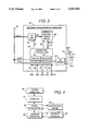
- a multiprocessor personal computer 10' comprises a planar board 11 and a processor card 12' mounted on or connected to such board.
- Processor card 12' differs from card 12 (FIG. 1) primarily by the addition of two microprocessors MP2 and MP3, local devices LD2 and LD3, and multiprocessor interrupt director logic 60, and related circuit connections, and by the substitution of multiprocessor arbitration logic 58 for logic 17 (FIG. 1).
- microprocessor 14 is also designated MP1, and local devices 18 are also designated as LD1.
- MP2, LD2, MP3 and LD3 are also referenced as 50, 52, 54, and 56.
- Local bus 16' is a multiprocessor local bus that is connected to the above additions and includes a plurality of transceivers (TCVRs) 19 that isolate the sections of the local bus that are respectively connected to the processors.
- Card 12' is a multiprocessor upgrade card that is a replacement for processor card 12 and is designed to be plugged into planar board 11 without having to change or modify planar board 11 or any of the components thereon.
- the computer thus includes a tightly coupled multiprocessor arrangement in which the system memory and I/O devices are shared by each of the processors.
- Processor MP1 has an input line 74-1 for receiving input request signal INT1, an input line 64-1 for receiving a local bus grant signal GR1, and an output line 66-1, for sending a bus request signal BREQ1.
- Processors MP2 and MP3 have similar lines for receiving and sending similar signals.
- the interrupt request signals INT1-INT3 are selectively transmitted on lines 74 from interrupt director 60.
- the bus grant signals GR1-GR3 are selectively transmitted on lines 64 from arbitration logic 58.
- the bus request signals BREQ1-BREQ3 are transmitted on lines 66 to arbitration logic 58.
- Arbitration logic 58 is connected to bus 16' and includes input lines 66 and 70 for receiving bus access request signals BREQ1-BREQ3 from processors 14, 50, and 54 and local bus request (LBR) signals from director 60.
- Logic 58 also has a plurality of output lines 64 and 68 for transmitting bus grant signals GR1-GR3 to the processors and local bus grant (LBG) signals to director 60.
- the GR1-3 signals are also transmitted over lines 64 to decode and control logic 88 (FIG. 3).
- Memory controller 20 has an input line 72 for receiving a local bus access (LBA) signal that selectively disables the controller and prevents the memory controller from propagating interrupt acknowledge signals to interrupt controller 36, as described hereinafter.
- LBA local bus access
- the multiple processors MP1-MP3, multiprocessor local bus 16', and multiprocessor arbitration logic 58 are standard elements of any tightly coupled multiprocessor system.
- the LBA signal has also been used in systems for controlling bus cache devices.
- multiprocessor interrupt director 60 referred to hereafter simply as the "director", comprises an interrupt vector (IV) register (REG) 80, an interrupt routing lookup device 82, decode and control logic 88, and interrupt (INT) drivers 90.
- Interrupt routing lookup device stores preassigned microprocessor identifiers (MP IDs) as a function of IV indexes. There are sixteen IV indexes corresponding to the sixteen different interrupts that computer 10' is configured for. Each index is derived from the four low-order bits of an interrupt vector stored in IV REG 80.
- Lookup device 82 has inputs connected to outputs of register 80 by lines 84.
- Register 80 has inputs connected to the data lines of bus 16' and provides a path or means through which routing device 82 can be loaded with preassigned values of MP IDs, under software control, during system initialization.
- IV REG 80 temporarily stores an interrupt vector transmitted from interrupt controller 36 so that the interrupt vector can later be read, during an emulated acknowledgement cycle, by the microprocessor assigned to process the particular interrupt. Also, during interrupt handling, lines 84 input an IV index from IV REG 80 to routing device 82 for looking up the predetermined MP ID assigned to the particular interrupt corresponding to the IV index. Device 82 has outputs connected by lines 86 to inputs of logic 88 for transmitting the looked up MP ID from device 82 to logic 88.
- Decode and control logic 88 is connected to the address (ADDR) and control (CTRL) lines of local bus 16' and has two input lines 40 and 68 respectively connected to receive an INT4 interrupt signal from controller 36 and a local bus grant signal LBG from arbitration logic 58.
- Logic 88 is further connected to lines 64 to receive the GR1-GR3 signals.
- Logic 88 also has two output lines 70 and 72 for respectively transmitting local bus request signal LBR to arbitration logic 58 and LBA signal to memory controller 20.
- Logic 88 is also connected to INT drivers 90 which selectively generate and transmit the interrupt signals INT1-INT3 to the selected multiprocessor MPx, where MPx is either MP1, MP2, or MP3.
- Logic 88 has two control lines 87 and 89 respectively connected to register 80 and device 82 for controlling operation thereof.
- Logic 88 comprises a means 91 for controlling interrupt vector transfer from the interrupt controller 36 to director 60 and to a selected microprocessor, and a means 93 for controlling interrupt request routing from interrupt controller 36 to director 60 and to the selected processor, in the manner described hereinafter.
- the general system operation 92 commences with the power being turned on in step 94.
- Step 96 then initializes the system in the normal manner except that the initialization is modified to include step 98 which loads routing lookup device 82 with the MP IDs as a function of the IV INDEX.
- the system then commences normal program execution 100.
- an interrupt occurs, the normal program execution is suspended and the interrupt is handled or processed in step 102.
- a return is made to program execution 100 which then continues at the point of suspension.
- Interrupt handling 102 begins in step 104 with one or more interrupting devices 41 detecting the occurrence of an external event(s). For simplicity, assume that only one event has occurred and the interrupting device, that has detected the occurrence of the event, transmits an interrupt signal over one of lines 38 to interrupt controller 36. In response to receipt of such interrupt, controller 36 stores the interrupt vector, corresponding to the interrupt in register 37. Controller 36 then transmits, in step 106, an INT4 interrupt request signal to director 60. In response to receiving interrupt request signal INT4, director 60 requests (step 108) access to local bus 16' by transmitting an LBR signal on line 70 to arbitration logic 58. Assuming there is no higher priority request, arbitration logic 58 then grants the request and transmits LBG signal on line 68 to director 60, in step 110.
- director 60 In response to the receipt of the LBG signal, director 60 then generates an interrupt acknowledge cycle in step 112 in accordance with the standard protocol used by a processor. In step 114, interrupt controller responds to the interrupt acknowledge cycle by transmitting the interrupt vector IV stored in register 37. Such IV is received by director 60 and stored in register 80, in step 116. Director 60, in step 118, then derives the IV index from IV REG 80 and uses it to look up the MP ID of the processor MPx preassigned to handle the interrupt. Then, director 60 selectively activates one of drivers 90 to send an interrupt request INTx to the specific microprocessor MPx, in step 120. The INTx signal is not broadcast or transmitted to any other microprocessor.
- director 60 effectively receives an interrupt request from interrupt controller 36 and routes or directs the request to the microprocessor assigned to handle and process the interrupt.
- Request routing means 93 controls the routing of an interrupt request from the interrupt controller to the specific processor MPx and performs steps 118 and 120.
- the selected MPx In response to receiving the INTx signal, the selected MPx then requests a bus access in step 122 by sending BREQx signal to arbitration logic 58. In response thereto, logic 58 sends a bus grant signal GRx to MPx in step 124. MPx then proceeds in step 126 to generate an interrupt acknowledge cycle. In step 128, director 60 decodes or detects the bus acknowledge cycle, and then sends a local bus access signal LBA to memory controller 20 to block the propagation of the interrupt cycle signals to interrupt controller 36. Director 60 then emulates, in step 130, what would have been the interrupt controller response, by transmitting the interrupt vector stored in register 80, to MPx. In response to the receipt of the vector, MPx then processes the particular interrupt be executing the interrupt handler for such interrupt, in step 132.
- Vector transfer means 91 Upon completion of processing the interrupt, a return is made in step 134 to the program that was being executed at the time the interrupt occurred.
- Vector transfer means 91 performs steps 108, 112, 116, 128, and 130 and thereby is operative to transfer the interrupt vector from register 37 to register 80 and thence to the selected microprocessor MPx.
- routing device 82 has been loaded with the MP ID values listed in Table I above. Assume also that an interrupt has occurred which causes an interrupt vector, having a value of "9", to be stored in IV reg 80 during step 116. As a result of step 118, an MP ID of "2" is transmitted indicating that MP2 is the processor selected to process the interrupt. Thus steps 120, 122, and 124 respectively produce INT2, BREQ2, and GR2 signals, which cause corresponding operations to occur.
- interrupt controller 36 stores an interrupt vector corresponding to the interrupt and transmits an interrupt request to director 60.
- director 50 In response to receiving the interrupt request, director 50 generates an interrupt acknowledge cycle during which the interrupt vector is transferred from the interrupt controller to the interrupt director.
- director 60 looks up the identity of the processor that has been preassigned to handle the specific interrupt and sends an interrupt request to only that processor.
- the specific processor In response to receiving the interrupt request, the specific processor then suspends execution of the current program and generates an interrupt acknowledge cycle during which the director blocks the interrupt controller from responding during the cycle. Instead, director 60 responds directly to the processor by transmitting the interrupt vector to the processor as part of the interrupt acknowledge cycle. The processor then processes the interrupt by executing the appropriate interrupt handler identified by the interrupt vector. Upon completion of the interrupt processing, control is returned to execution of the program that was interrupted.
Abstract
Description
              TABLE I
______________________________________
INT          MP        INT         MP
INDEX        ID        INDEX       ID
______________________________________
0            1         8           2
1            1         9           2
2            1         10          3
3            1         11          3
4            2         12          3
5            2         13          1
6            2         14          2
7            2         15          2
______________________________________
Claims (6)
Priority Applications (1)
| Application Number | Priority Date | Filing Date | Title |
|---|---|---|---|
| US08/067,361 US5381541A (en) | 1993-05-26 | 1993-05-26 | Computer system having planar board with single interrupt controller and processor card with plural processors and interrupt director |
Applications Claiming Priority (1)
| Application Number | Priority Date | Filing Date | Title |
|---|---|---|---|
| US08/067,361 US5381541A (en) | 1993-05-26 | 1993-05-26 | Computer system having planar board with single interrupt controller and processor card with plural processors and interrupt director |
Publications (1)
| Publication Number | Publication Date |
|---|---|
| US5381541A true US5381541A (en) | 1995-01-10 |
Family
ID=22075504
Family Applications (1)
| Application Number | Title | Priority Date | Filing Date |
|---|---|---|---|
| US08/067,361 Expired - Fee Related US5381541A (en) | 1993-05-26 | 1993-05-26 | Computer system having planar board with single interrupt controller and processor card with plural processors and interrupt director |
Country Status (1)
| Country | Link |
|---|---|
| US (1) | US5381541A (en) |
Cited By (16)
| Publication number | Priority date | Publication date | Assignee | Title |
|---|---|---|---|---|
| WO1996027156A1 (en) * | 1995-03-01 | 1996-09-06 | Intel Corporation | Interrupt steering for a computer system |
| US5555413A (en) * | 1995-02-17 | 1996-09-10 | International Business Machines Corporation | Computer system and method with integrated level and edge interrupt requests at the same interrupt priority |
| US5581770A (en) * | 1992-06-04 | 1996-12-03 | Mitsubishi Denki Kabushiki Kaisha | Floating interruption handling system and method |
| US5640570A (en) * | 1996-01-26 | 1997-06-17 | International Business Machines Corporation | Information handling system for transmitting contents of line register from asynchronous controller to shadow register in another asynchronous controller determined by shadow register address buffer |
| US5701495A (en) * | 1993-09-20 | 1997-12-23 | International Business Machines Corporation | Scalable system interrupt structure for a multi-processing system |
| US5727219A (en) * | 1995-03-13 | 1998-03-10 | Sun Microsystems, Inc. | Virtual input/output processor utilizing an interrupt handler |
| US5828891A (en) * | 1995-12-20 | 1998-10-27 | International Business Machines Corporation | Multilevel interrupt device |
| US5850555A (en) * | 1995-12-19 | 1998-12-15 | Advanced Micro Devices, Inc. | System and method for validating interrupts before presentation to a CPU |
| US5872982A (en) * | 1994-12-28 | 1999-02-16 | Compaq Computer Corporation | Reducing the elapsed time period between an interrupt acknowledge and an interrupt vector |
| US5909571A (en) * | 1995-05-01 | 1999-06-01 | Apple Computer, Inc. | Clock distribution for processor and host cards |
| US6192439B1 (en) * | 1998-08-11 | 2001-02-20 | Hewlett-Packard Company | PCI-compliant interrupt steering architecture |
| US20070156941A1 (en) * | 2004-10-14 | 2007-07-05 | Dell Products L.P. | Method for synchronizing processors following a memory hot plug event |
| US20080313369A1 (en) * | 2007-06-14 | 2008-12-18 | International Business Machines Corporation | Multi-node configuration of processor cards connected via processor fabrics |
| US20090198850A1 (en) * | 2008-02-05 | 2009-08-06 | Kumiko Suzuki | Processor, electronic apparatus, interruption control method and interruption control program |
| US20090327555A1 (en) * | 2008-06-26 | 2009-12-31 | Microsoft Corporation | Processor Interrupt Determination |
| US20100262749A1 (en) * | 2005-07-25 | 2010-10-14 | Surf Commmunication Solutions Ltd. | Communication Processor Board |
Citations (14)
| Publication number | Priority date | Publication date | Assignee | Title |
|---|---|---|---|---|
| US4268904A (en) * | 1978-02-15 | 1981-05-19 | Tokyo Shibaura Electric Co., Ltd. | Interruption control method for multiprocessor system |
| US4271468A (en) * | 1979-11-06 | 1981-06-02 | International Business Machines Corp. | Multiprocessor mechanism for handling channel interrupts |
| US4644465A (en) * | 1983-06-22 | 1987-02-17 | Hitachi, Ltd. | Apparatus for controlling I/O interrupt in multiprocessor system |
| US4727480A (en) * | 1984-07-09 | 1988-02-23 | Wang Laboratories, Inc. | Emulation of a data processing system |
| US4833598A (en) * | 1986-07-24 | 1989-05-23 | Hitachi, Ltd. | I/O interrupt handling mechanism in a multiprocessor system |
| US4914570A (en) * | 1986-09-15 | 1990-04-03 | Counterpoint Computers, Inc. | Process distribution and sharing system for multiple processor computer system |
| US4933846A (en) * | 1987-04-24 | 1990-06-12 | Network Systems Corporation | Network communications adapter with dual interleaved memory banks servicing multiple processors |
| US4959781A (en) * | 1988-05-16 | 1990-09-25 | Stardent Computer, Inc. | System for assigning interrupts to least busy processor that already loaded same class of interrupt routines |
| US4965717A (en) * | 1988-12-09 | 1990-10-23 | Tandem Computers Incorporated | Multiple processor system having shared memory with private-write capability |
| US5003466A (en) * | 1987-02-06 | 1991-03-26 | At&T Bell Laboratories | Multiprocessing method and arrangement |
| US5043882A (en) * | 1989-03-03 | 1991-08-27 | Nec Corporation | Interrupt controller for multiprocessor systems |
| US5067071A (en) * | 1985-02-27 | 1991-11-19 | Encore Computer Corporation | Multiprocessor computer system employing a plurality of tightly coupled processors with interrupt vector bus |
| US5155838A (en) * | 1988-04-28 | 1992-10-13 | Kabushiki Kaisha Toshiba | Computer system with emulation mechanism |
| US5179707A (en) * | 1990-06-01 | 1993-01-12 | At&T Bell Laboratories | Interrupt processing allocation in a multiprocessor system |
-
1993
- 1993-05-26 US US08/067,361 patent/US5381541A/en not_active Expired - Fee Related
Patent Citations (15)
| Publication number | Priority date | Publication date | Assignee | Title |
|---|---|---|---|---|
| US4268904A (en) * | 1978-02-15 | 1981-05-19 | Tokyo Shibaura Electric Co., Ltd. | Interruption control method for multiprocessor system |
| US4271468A (en) * | 1979-11-06 | 1981-06-02 | International Business Machines Corp. | Multiprocessor mechanism for handling channel interrupts |
| US4644465A (en) * | 1983-06-22 | 1987-02-17 | Hitachi, Ltd. | Apparatus for controlling I/O interrupt in multiprocessor system |
| US4727480A (en) * | 1984-07-09 | 1988-02-23 | Wang Laboratories, Inc. | Emulation of a data processing system |
| US5067071A (en) * | 1985-02-27 | 1991-11-19 | Encore Computer Corporation | Multiprocessor computer system employing a plurality of tightly coupled processors with interrupt vector bus |
| US4833598A (en) * | 1986-07-24 | 1989-05-23 | Hitachi, Ltd. | I/O interrupt handling mechanism in a multiprocessor system |
| US4914570A (en) * | 1986-09-15 | 1990-04-03 | Counterpoint Computers, Inc. | Process distribution and sharing system for multiple processor computer system |
| US5003466A (en) * | 1987-02-06 | 1991-03-26 | At&T Bell Laboratories | Multiprocessing method and arrangement |
| US4933846A (en) * | 1987-04-24 | 1990-06-12 | Network Systems Corporation | Network communications adapter with dual interleaved memory banks servicing multiple processors |
| US5155838A (en) * | 1988-04-28 | 1992-10-13 | Kabushiki Kaisha Toshiba | Computer system with emulation mechanism |
| US4959781A (en) * | 1988-05-16 | 1990-09-25 | Stardent Computer, Inc. | System for assigning interrupts to least busy processor that already loaded same class of interrupt routines |
| US4965717A (en) * | 1988-12-09 | 1990-10-23 | Tandem Computers Incorporated | Multiple processor system having shared memory with private-write capability |
| US4965717B1 (en) * | 1988-12-09 | 1993-05-25 | Tandem Computers Inc | |
| US5043882A (en) * | 1989-03-03 | 1991-08-27 | Nec Corporation | Interrupt controller for multiprocessor systems |
| US5179707A (en) * | 1990-06-01 | 1993-01-12 | At&T Bell Laboratories | Interrupt processing allocation in a multiprocessor system |
Cited By (25)
| Publication number | Priority date | Publication date | Assignee | Title |
|---|---|---|---|---|
| US5581770A (en) * | 1992-06-04 | 1996-12-03 | Mitsubishi Denki Kabushiki Kaisha | Floating interruption handling system and method |
| US5701495A (en) * | 1993-09-20 | 1997-12-23 | International Business Machines Corporation | Scalable system interrupt structure for a multi-processing system |
| US5872982A (en) * | 1994-12-28 | 1999-02-16 | Compaq Computer Corporation | Reducing the elapsed time period between an interrupt acknowledge and an interrupt vector |
| US5555413A (en) * | 1995-02-17 | 1996-09-10 | International Business Machines Corporation | Computer system and method with integrated level and edge interrupt requests at the same interrupt priority |
| US5640571A (en) * | 1995-03-01 | 1997-06-17 | Intel Corporation | Interrupt steering for a computer system |
| WO1996027156A1 (en) * | 1995-03-01 | 1996-09-06 | Intel Corporation | Interrupt steering for a computer system |
| KR100392326B1 (en) * | 1995-03-13 | 2003-10-23 | 썬 마이크로시스템즈, 인코포레이티드 | Virtual input / output processor |
| US5727219A (en) * | 1995-03-13 | 1998-03-10 | Sun Microsystems, Inc. | Virtual input/output processor utilizing an interrupt handler |
| US5909571A (en) * | 1995-05-01 | 1999-06-01 | Apple Computer, Inc. | Clock distribution for processor and host cards |
| US5850555A (en) * | 1995-12-19 | 1998-12-15 | Advanced Micro Devices, Inc. | System and method for validating interrupts before presentation to a CPU |
| US5828891A (en) * | 1995-12-20 | 1998-10-27 | International Business Machines Corporation | Multilevel interrupt device |
| US5640570A (en) * | 1996-01-26 | 1997-06-17 | International Business Machines Corporation | Information handling system for transmitting contents of line register from asynchronous controller to shadow register in another asynchronous controller determined by shadow register address buffer |
| US6192439B1 (en) * | 1998-08-11 | 2001-02-20 | Hewlett-Packard Company | PCI-compliant interrupt steering architecture |
| US7500040B2 (en) * | 2004-10-14 | 2009-03-03 | Dell Products L.P. | Method for synchronizing processors following a memory hot plug event |
| US20070156941A1 (en) * | 2004-10-14 | 2007-07-05 | Dell Products L.P. | Method for synchronizing processors following a memory hot plug event |
| US20100262749A1 (en) * | 2005-07-25 | 2010-10-14 | Surf Commmunication Solutions Ltd. | Communication Processor Board |
| US7991940B2 (en) | 2005-07-25 | 2011-08-02 | Surf Communication Solutions Ltd. | Communication processor board |
| US20080313369A1 (en) * | 2007-06-14 | 2008-12-18 | International Business Machines Corporation | Multi-node configuration of processor cards connected via processor fabrics |
| US7783813B2 (en) * | 2007-06-14 | 2010-08-24 | International Business Machines Corporation | Multi-node configuration of processor cards connected via processor fabrics |
| US20100268986A1 (en) * | 2007-06-14 | 2010-10-21 | International Business Machines Corporation | Multi-node configuration of processor cards connected via processor fabrics |
| US8095691B2 (en) | 2007-06-14 | 2012-01-10 | International Business Machines Corporation | Multi-node configuration of processor cards connected via processor fabrics |
| US20090198850A1 (en) * | 2008-02-05 | 2009-08-06 | Kumiko Suzuki | Processor, electronic apparatus, interruption control method and interruption control program |
| US7984218B2 (en) * | 2008-02-05 | 2011-07-19 | Nec Corporation | Processor, electronic apparatus, interruption control method and interruption control program |
| US20090327555A1 (en) * | 2008-06-26 | 2009-12-31 | Microsoft Corporation | Processor Interrupt Determination |
| US8024504B2 (en) | 2008-06-26 | 2011-09-20 | Microsoft Corporation | Processor interrupt determination |
Similar Documents
| Publication | Publication Date | Title |
|---|---|---|
| US5381541A (en) | Computer system having planar board with single interrupt controller and processor card with plural processors and interrupt director | |
| US4006466A (en) | Programmable interface apparatus and method | |
| US4000487A (en) | Steering code generating apparatus for use in an input/output processing system | |
| US6711643B2 (en) | Method and apparatus for interrupt redirection for arm processors | |
| EP0827085B1 (en) | Method and apparatus for distributing interrupts in a scalable symmetric multiprocessor system without changing the bus width or bus protocol | |
| US4942519A (en) | Coprocessor having a slave processor capable of checking address mapping | |
| US4090239A (en) | Interval timer for use in an input/output system | |
| KR100385871B1 (en) | Interrupt controller | |
| US6134579A (en) | Semaphore in system I/O space | |
| US5944809A (en) | Method and apparatus for distributing interrupts in a symmetric multiprocessor system | |
| US5987538A (en) | Apparatus for initiating generation of an inter-processor interrupt by a peripheral device not directly connected to any of the multi-processor local interrupt controllers | |
| US4736319A (en) | Interrupt mechanism for multiprocessing system having a plurality of interrupt lines in both a global bus and cell buses | |
| US5764996A (en) | Method and apparatus for optimizing PCI interrupt binding and associated latency in extended/bridged PCI busses | |
| US6470408B1 (en) | Apparatus and method for delivering interrupts via an APIC bus to IA-32 processors | |
| US5805844A (en) | Control circuit for an interface between a PCI bus and a module bus | |
| US10990544B2 (en) | PCIE root complex message interrupt generation method using endpoint | |
| WO1995006286A2 (en) | Integrated multi-threaded host adapter | |
| US6339808B1 (en) | Address space conversion to retain software compatibility in new architectures | |
| US5493655A (en) | Method and apparatus for upgrading a data processing system from a single processor system to a multiprocessor system | |
| US11741039B2 (en) | Peripheral component interconnect express device and method of operating the same | |
| US5524211A (en) | System for employing select, pause, and identification registers to control communication among plural processors | |
| US6625679B1 (en) | Apparatus and method for converting interrupt transactions to interrupt signals to distribute interrupts to IA-32 processors | |
| US5590338A (en) | Combined multiprocessor interrupt controller and interprocessor communication mechanism | |
| US6701388B1 (en) | Apparatus and method for the exchange of signal groups between a plurality of components in a digital signal processor having a direct memory access controller | |
| US20060136642A1 (en) | Interrupt distribution for multiprocessor system |
Legal Events
| Date | Code | Title | Description |
|---|---|---|---|
| AS | Assignment |
Owner name: INTERNATIONAL BUSINESS MACHINES CORP., NEW YORK Free format text: ASSIGNMENT OF ASSIGNORS INTEREST;ASSIGNORS:BEGUN, RALPH MURRAY;TURNER, MICHAEL ROBERT;REEL/FRAME:006563/0537 Effective date: 19930526 |
|
| FPAY | Fee payment |
Year of fee payment: 4 |
|
| FEPP | Fee payment procedure |
Free format text: PAYOR NUMBER ASSIGNED (ORIGINAL EVENT CODE: ASPN); ENTITY STATUS OF PATENT OWNER: LARGE ENTITY |
|
| FPAY | Fee payment |
Year of fee payment: 8 |
|
| AS | Assignment |
Owner name: LENOVO (SINGAPORE) PTE LTD.,SINGAPORE Free format text: ASSIGNMENT OF ASSIGNORS INTEREST;ASSIGNOR:INTERNATIONAL BUSINESS MACHINES CORPORATION;REEL/FRAME:016891/0507 Effective date: 20050520 Owner name: LENOVO (SINGAPORE) PTE LTD., SINGAPORE Free format text: ASSIGNMENT OF ASSIGNORS INTEREST;ASSIGNOR:INTERNATIONAL BUSINESS MACHINES CORPORATION;REEL/FRAME:016891/0507 Effective date: 20050520 |
|
| REMI | Maintenance fee reminder mailed | ||
| LAPS | Lapse for failure to pay maintenance fees | ||
| STCH | Information on status: patent discontinuation |
Free format text: PATENT EXPIRED DUE TO NONPAYMENT OF MAINTENANCE FEES UNDER 37 CFR 1.362 |
|
| FP | Lapsed due to failure to pay maintenance fee |
Effective date: 20070110 |