US5382909A - Method for detecting and obtaining information about changes in variables - Google Patents
Method for detecting and obtaining information about changes in variables Download PDFInfo
- Publication number
- US5382909A US5382909A US08/100,710 US10071093A US5382909A US 5382909 A US5382909 A US 5382909A US 10071093 A US10071093 A US 10071093A US 5382909 A US5382909 A US 5382909A
- Authority
- US
- United States
- Prior art keywords
- locating
- source
- connection
- locating member
- event
- Prior art date
- Legal status (The legal status is an assumption and is not a legal conclusion. Google has not performed a legal analysis and makes no representation as to the accuracy of the status listed.)
- Expired - Lifetime
Links
Images


Classifications
-
- G—PHYSICS
- G01—MEASURING; TESTING
- G01R—MEASURING ELECTRIC VARIABLES; MEASURING MAGNETIC VARIABLES
- G01R31/00—Arrangements for testing electric properties; Arrangements for locating electric faults; Arrangements for electrical testing characterised by what is being tested not provided for elsewhere
- G01R31/08—Locating faults in cables, transmission lines, or networks
-
- G—PHYSICS
- G01—MEASURING; TESTING
- G01D—MEASURING NOT SPECIALLY ADAPTED FOR A SPECIFIC VARIABLE; ARRANGEMENTS FOR MEASURING TWO OR MORE VARIABLES NOT COVERED IN A SINGLE OTHER SUBCLASS; TARIFF METERING APPARATUS; MEASURING OR TESTING NOT OTHERWISE PROVIDED FOR
- G01D11/00—Component parts of measuring arrangements not specially adapted for a specific variable
-
- G—PHYSICS
- G01—MEASURING; TESTING
- G01K—MEASURING TEMPERATURE; MEASURING QUANTITY OF HEAT; THERMALLY-SENSITIVE ELEMENTS NOT OTHERWISE PROVIDED FOR
- G01K7/00—Measuring temperature based on the use of electric or magnetic elements directly sensitive to heat ; Power supply therefor, e.g. using thermoelectric elements
- G01K7/16—Measuring temperature based on the use of electric or magnetic elements directly sensitive to heat ; Power supply therefor, e.g. using thermoelectric elements using resistive elements
- G01K7/18—Measuring temperature based on the use of electric or magnetic elements directly sensitive to heat ; Power supply therefor, e.g. using thermoelectric elements using resistive elements the element being a linear resistance, e.g. platinum resistance thermometer
-
- G—PHYSICS
- G01—MEASURING; TESTING
- G01M—TESTING STATIC OR DYNAMIC BALANCE OF MACHINES OR STRUCTURES; TESTING OF STRUCTURES OR APPARATUS, NOT OTHERWISE PROVIDED FOR
- G01M3/00—Investigating fluid-tightness of structures
- G01M3/02—Investigating fluid-tightness of structures by using fluid or vacuum
- G01M3/04—Investigating fluid-tightness of structures by using fluid or vacuum by detecting the presence of fluid at the leakage point
- G01M3/042—Investigating fluid-tightness of structures by using fluid or vacuum by detecting the presence of fluid at the leakage point by using materials which expand, contract, disintegrate, or decompose in contact with a fluid
- G01M3/045—Investigating fluid-tightness of structures by using fluid or vacuum by detecting the presence of fluid at the leakage point by using materials which expand, contract, disintegrate, or decompose in contact with a fluid with electrical detection means
-
- G—PHYSICS
- G01—MEASURING; TESTING
- G01M—TESTING STATIC OR DYNAMIC BALANCE OF MACHINES OR STRUCTURES; TESTING OF STRUCTURES OR APPARATUS, NOT OTHERWISE PROVIDED FOR
- G01M3/00—Investigating fluid-tightness of structures
- G01M3/02—Investigating fluid-tightness of structures by using fluid or vacuum
- G01M3/04—Investigating fluid-tightness of structures by using fluid or vacuum by detecting the presence of fluid at the leakage point
- G01M3/16—Investigating fluid-tightness of structures by using fluid or vacuum by detecting the presence of fluid at the leakage point using electric detection means
- G01M3/165—Investigating fluid-tightness of structures by using fluid or vacuum by detecting the presence of fluid at the leakage point using electric detection means by means of cables or similar elongated devices, e.g. tapes
-
- G—PHYSICS
- G01—MEASURING; TESTING
- G01M—TESTING STATIC OR DYNAMIC BALANCE OF MACHINES OR STRUCTURES; TESTING OF STRUCTURES OR APPARATUS, NOT OTHERWISE PROVIDED FOR
- G01M3/00—Investigating fluid-tightness of structures
- G01M3/02—Investigating fluid-tightness of structures by using fluid or vacuum
- G01M3/04—Investigating fluid-tightness of structures by using fluid or vacuum by detecting the presence of fluid at the leakage point
- G01M3/16—Investigating fluid-tightness of structures by using fluid or vacuum by detecting the presence of fluid at the leakage point using electric detection means
- G01M3/18—Investigating fluid-tightness of structures by using fluid or vacuum by detecting the presence of fluid at the leakage point using electric detection means for pipes, cables or tubes; for pipe joints or seals; for valves; for welds; for containers, e.g. radiators
-
- G—PHYSICS
- G01—MEASURING; TESTING
- G01N—INVESTIGATING OR ANALYSING MATERIALS BY DETERMINING THEIR CHEMICAL OR PHYSICAL PROPERTIES
- G01N27/00—Investigating or analysing materials by the use of electric, electrochemical, or magnetic means
- G01N27/02—Investigating or analysing materials by the use of electric, electrochemical, or magnetic means by investigating impedance
- G01N27/04—Investigating or analysing materials by the use of electric, electrochemical, or magnetic means by investigating impedance by investigating resistance
- G01N27/048—Investigating or analysing materials by the use of electric, electrochemical, or magnetic means by investigating impedance by investigating resistance for determining moisture content of the material
-
- G—PHYSICS
- G01—MEASURING; TESTING
- G01R—MEASURING ELECTRIC VARIABLES; MEASURING MAGNETIC VARIABLES
- G01R31/00—Arrangements for testing electric properties; Arrangements for locating electric faults; Arrangements for electrical testing characterised by what is being tested not provided for elsewhere
- G01R31/08—Locating faults in cables, transmission lines, or networks
- G01R31/081—Locating faults in cables, transmission lines, or networks according to type of conductors
- G01R31/083—Locating faults in cables, transmission lines, or networks according to type of conductors in cables, e.g. underground
-
- G—PHYSICS
- G08—SIGNALLING
- G08B—SIGNALLING OR CALLING SYSTEMS; ORDER TELEGRAPHS; ALARM SYSTEMS
- G08B23/00—Alarms responsive to unspecified undesired or abnormal conditions
-
- G—PHYSICS
- G08—SIGNALLING
- G08B—SIGNALLING OR CALLING SYSTEMS; ORDER TELEGRAPHS; ALARM SYSTEMS
- G08B25/00—Alarm systems in which the location of the alarm condition is signalled to a central station, e.g. fire or police telegraphic systems
- G08B25/01—Alarm systems in which the location of the alarm condition is signalled to a central station, e.g. fire or police telegraphic systems characterised by the transmission medium
- G08B25/018—Sensor coding by detecting magnitude of an electrical parameter, e.g. resistance
-
- H—ELECTRICITY
- H01—ELECTRIC ELEMENTS
- H01H—ELECTRIC SWITCHES; RELAYS; SELECTORS; EMERGENCY PROTECTIVE DEVICES
- H01H35/00—Switches operated by change of a physical condition
- H01H35/42—Switches operated by change of humidity
Definitions
- This invention relates to methods and apparatus for detecting and obtaining information about (particularly locating) changes in variables which take place at one or more locations along an elongate path.
- a number of methods have been used (or proposed for use) to detect changes in variables along an elongate path, e.g. the occurrence of a leak (of water or another liquid or gas), insufficient or excessive pressure, too high or too low a temperature, the presence or absence of light or another form of electromagnetic radiation, or a change in the physical position of a movable member, e.g. a valve in a chemical process plant or a window in a building fitted with a burglar alarm system. Changes of this kind are referred to in this specification by the generic term "event”.
- Such detection methods are for example highly desirable to detect leaks from steam lines into thermal insulation surrounding such lines, leaks from tanks and pipes containing corrosive or noxious chemicals, or leakage or condensation of water under floors or within telecommunication or electrical power systems.
- time domain reflectometer techniques make use of time domain reflectometer techniques (and are, therefore, expensive), and/or give unreliable results when used over usefully long elongate paths or under conditions when there may be a substantial and unknown variation along the length of the path of a variable which effects the accuracy of the measurement (especially temperature), and/or make use of electrical conductors whose primary purpose is to carry a current (e.g. a telecommunication signal) under normal operating conditions (and which therefore have resistance and uniformity characteristics consistent with that purpose), and/or cannot be used when the event causes electrical connection between two conductors through a connection which is of high or indeterminate resistance, e.g. an ionically conductive connecting element.
- a current e.g. a telecommunication signal
- At least one electrical connection is made between an elongate source member and an elongate locating member of known impedance characteristics, the connection or connections being effective at a first point at which the event takes place (or whose location as defined by some other characteristic of the event).
- the making of the connection enables the formation of a test circuit which contains the electrical connection(s) and that part of the locating member which lies between the first point and a second point on the locating member whose location is known.
- test circuit contains a balancing component which is (a) connected in series with that part of the locating member which lies between the first and second points, and (b) has an impedance which is substantially equal to the difference between (i) the total impedance of the locating member and (ii) the impedance of that part of the locating member between the first and second points.
- a balancing component which is (a) connected in series with that part of the locating member which lies between the first and second points, and (b) has an impedance which is substantially equal to the difference between (i) the total impedance of the locating member and (ii) the impedance of that part of the locating member between the first and second points.
- the system preferably makes use of a locating member having an impedance which is selected to give a desired degree of accuracy in locating the first point, and which preferably does not vary substantially within the temperature range in which the system operates.
- the "first point” When the occurrence of the event causes a single or very short connection to be made between the locating member and the source member, then the "first point" will of course be easily identified, since it is the only connection point.
- the "first point" i.e. the point whose location can be determined from the observed voltage drop, is some intermediate point which can conveniently be referred to as the "electrical center” of the various connections. If there are connections at two or more spaced-apart locations, the "electrical center” may be at a location at which there is no connection between the locating and source members.
- connection to the locating member is sometimes referred herein as being "effective" at the first point.
- this is intended to include situations in which a plurality of electrical connections are made between the locating member and the source member, with the electrical center of the connections being at the first point.
- the first point will be at, or close to, that point at which a connection is made and which is closest to the second point; however, it is important to realize that this is not necessarily the case.
- a particularly important advantage is that the information obtained can be independent the impedance of the connection to the locating member, i.e. the information obtained remains the same even if a substantial and unknown change is made in the impedance of the connection. This is the case, for example, when the event is the presence of water or another electrolyte which makes an ionic connection between the source and locating members.
- the invention provides a method for monitoring for the occurrence of an event, and for detecting and obtaining information about the event upon its occurrence, which method comprises
- connection enabling the formation of a test circuit which comprises (i) that part of the locating member which lies between the first point and a second point having a known location on the locating member, (ii) the connection, (iii) the power source, and (iv) a balancing component which is connected in series with said part (i) and which has an impedance equal to the difference between Z total and the impedance of said part (i), the power source causing an electrical current of known size to be transmitted between the first and second points on the locating member; and
- the current and the locating member being such that, by measuring the voltage drop between the first and second points, the spatial relationship between the first and second points can be determined;
- the system comprises an elongate electrically conductive auxiliary member
- the auxiliary member is electrically connected to the source member at the far end of the path
- the balancing component (iv) in the test circuit is provided by that part of the source member which lies between the first point and the far end of the path.
- the voltage drop between the first and second points is determined by means of a voltage-measuring device which forms part of a reference circuit, the reference circuit comprising
- an elongate electrically conductive return member which (i) is electrically connected to the locating member at the second point and at another point on the locating member whose distance from the second point is at least as great as the distance from the second point to the first point, both distances being measured along the locating member, and (ii) is otherwise insulated from the locating member, the voltage-measuring device having an impedance which is very high by comparison with any unknown part of the impedance of the other components of the reference circuit.
- the invention provides apparatus suitable for carrying out the method defined above, in particular apparatus comprising
- an elongate electrically conductive locating member which comprises a plurality of available connection points, which has an impedance Z total between the most widely separated available connection points, and whose impedance from one end to any of the connection points defines the spatial relationship between that end and that point;
- an event-sensitive connection means which is present at said plurality of available connection points and which, upon occurrence of an event, at any of said available connection points, permits or effects electrical connection between the locating member and the source member at one or more of the connection points, the connection being effective at a first point on the locating member which is defined by at least one characteristic of the event;
- a power source which is electrically connected to the second point on the locating member and which, in the absence of an event, is not otherwise connected to the locating member, so that, when occurrence of an event causes an electrical connection to be made between the locating and source members, this enables the formation of a test circuit which comprises (i) that part of the locating member which lies between the first and second points, (ii) the connection, (iii) the power source, and (iv) a component which is connected in series with said part (i) and which has an impedance substantially equal to the difference between Z total and the impedance of said part (i), the power source causing an electrical current of known size to be transmitted between the first and second points on the locating member.
- the apparatus preferably also includes an auxiliary member and/or a return member as described above.
- the source and locating members, and the auxiliary and return members are physically secured together to form a sensor cable.
- a sensor cable at least one, and preferably all, of the members are in a wrapped, e.g. braided, configuration.
- the balancing component (iv) results in a system whose sensitivity is independent of the location of the event. Another important advantage is that since the impedance of the connection(s) between the locating and source members is the only variable impedance in the test circuit (or in other circuits which can be created by appropriate switching arrangements), it is possible to determine the impedance of the connection(s). This is useful, for example, in order to determine whether the impedance is changing with time.
- the locating member having "a plurality of available connection points"
- the power source in the test circuit is a controlled current source, to prevent the delivery of information when the impedance of the connection is within some predetermined range (e.g. above some predetermined level), even when part or all of that predetermined range is not such as to cause the current in the test circuit to fall below the "fixed" level. Under these circumstances, the information will be correct, but unwanted, and in accordance with another embodiment of the present invention, the system is modified to include one or more components which
- the power source in the test circuit is a constant voltage source
- some predetermined range e.g. above a certain level or below a certain level.
- the power source in the test circuit has an output voltage V volts and causes an electrical current I amps of known size to be transmitted between the first and second points on the locating member, and information concerning the event is obtained only when the value of the ratio V/I is within a predetermined range (i.e. above a particular value, or below a particular value, or between two particular values).
- Another embodiment of the invention makes use of a reference impedance connected in series with the locating member.
- the voltage drop down the locating member, from one end to the location of the event, and the voltage drop across the reference impedance, are determined.
- a divider provides a ratio between the voltage drops and the location of the event is determined from that ratio.
- a power supply e.g. a current supply
- a constant current source e.g. a constant current source
- variations in "constant current” do not matter, that is, the output of the power supply need not be monitored or known at all moments of time.
- divider is used herein to denote any device which obtains from the measurements of the voltage drops the desired information about the event.
- the apparatus of the invention preferably also contain a display which is activated by the divider when it provides a ratio between the first and second voltage drops.
- the electrical connection of the source and locating members is effected by the swelling of a swellable member which swells when the event occurs.
- the connection can be effected in a number of different ways.
- the swellable member is adjacent to a separator which has apertures passing therethrough, and the swelling of the swellable member causes an electrical path to be formed between the conductive members, through the apertures of the separator.
- the swellable member is a bridging member which, upon occurrence of the event, swells into contact with the source and locating members and bridges them, whereby an electrical path is formed therebetween.
- the swellable member is part of a device comprising:
- the source member in the form of a member which is hollow and surrounds the support core, spacer member and first conductive member;
- said spacer member projecting outwardly from the support core a greater distance than the locating member such that in the absence of an event it spaces the source and locating members from each other.
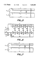
- FIGS. 1 and 5 to 11 are schematic circuit diagrams of systems of the invention.
- FIGS. 2 to 4 are graphs showing how the voltage drop between the first and second points on the locating member can vary in different methods of the invention.
- FIG. 1 there is an elongate locating member 11, an elongate source member 12, an elongate auxiliary member 13, a voltage-measuring device 14, a power source 15 and an elongate return member 16.
- the source member is electrically connected, through the auxiliary member and the power source, to the near end of the locating member; in the absence of an event, there is no other electrical connection between the locating member and the source member.
- an event-sensitive connection means (this term being used to include a continuous event-sensitive connection means and a plurality of spaced-apart event-sensitive connection means) which becomes conductive at any location at which an event takes place.
- FIG. 1 an event has taken place at a first point 1 which lies somewhere on the locating member, but whose location is otherwise unknown.
- the power source 15 is connected to the locating member at the near end thereof, designated by the numeral 2, which is the "second point" in the definitions given above of the method and apparatus of the invention.
- the second point could be at any point of known location between the end of locating member 11 and the connection point 1, providing that the voltage-measuring device is arranged to measure the voltage drop between the first and second points.
- the power source is also connected to the far end of the source member via the auxiliary member 13.
- the voltage-measuring device is connected to the second point 2 on the locating member and (via the return member 16) to the far end of the locating member.
- the voltage-measuring device forms part of a reference circuit which comprises the device, the locating member, and the return member.
- the accuracy with which the first point can be located is limited by the ratio of the impedance of the voltage-measuring device to any unknown part of the impedance of the other components of the reference circuit, and in most cases it is convenient to use components such that the ratio of the impedance of the device to the total impedance of the rest of the reference circuit is very high. Accordingly, these ratios should preferably be at least 100, particularly at least 1,000, especially at least 10,000.
- the resistance of the connection between the locating and source members, and the resistance of the other components of the test circuit do not affect the accuracy of the information obtained.
- the information provided about the event is its location, particularly when the event takes place at (or near) the location of the first point.
- the information provided can be other information; for example when the temperature at a particular location is being monitored, one point on the locating member can be identified when the temperature is in one temperature range and another point can be identified when the temperature is in a different temperature range.
- the location of the event may be at, or close to, the first point on the locating member.
- one or more remote event-detecting stations can be connected, electrically or otherwise, to different points on a central locating member, the locations of the connection points being characteristic of the locations of the event-detecting stations.
- the method of the invention can provide some, but not necessarily all, the desired information about the event.
- the method can usefully be employed to determine that a given event (e.g. the opening of a valve) has taken place at one or more of a relatively small number of different locations, out of a relatively large number of possible locations for the event, leaving it to visual inspection or some other form of test (which may be a further and different method of the invention) to determine precisely where the event has taken place.
- the event which is detected in the method of the invention can be an event which is not desired (a fault) or an event which is desired.
- the event can be the existence of a particular condition or a change in a single variable, e.g. an increase in pressure above a particular value, or a simultaneous or sequential change in two or more variables, e.g. an increase in pressure accompanied by an increase in temperature.
- the event can be a change in a variable which lasts for only a very short time, or a change in a variable which is maintained for some minimum time.
- the event can be of any kind which directly or indirectly permits or causes the current to be transmitted between the first point and the second point on the locating member. As noted above, the information obtained is independent of the impedance of the connection.
- connection between the locating and source members can be of any kind, for example an electronic connection (which can be of substantially zero impedance or can have substantial impedance), or an ionic connection resulting from the presence of an electrolyte, or an inductive connection.
- the change which takes place in order to effect the connection between the locating and source conductors is preferably a reversible change.
- the invention is also useful when the change is a permanent one, so that the apparatus must be replaced or repaired before the system is operational again.
- the system can be arranged so that it signals an event only while the event is taking place or so that it signals that an event has occurred in the past; in the latter case, the system will normally be arranged so that it can be reset.
- Examples of events which can be detected include, but are not limited to, the following.
- the event-sensitive connection means can be merely a space between the locating and source members, or it can be a connection member on which the electrolyte collects or which absorbs the electrolyte.
- the locating and source members are physically contacted by a connecting member which insulates them from each other at T 1 and connects them no each other at T 2 .
- the connecting member can comprise (a) a first material and (b) a second material which is dispersed in the first material and which forms mobile ionic species when the temperature changes from T 1 to T 2 .
- the first material can be one which changes phase, e.g. melts, when the temperature changes from T 1 to T 2 .
- the locating and source members are separated from each other by a deformable insulating medium, e.g. an insulating medium which is at least in part a fluid, e.g. air, and the apparatus comprises a connecting member which changes shape when the temperature changes from T 1 to T 2 , thus forcing the members into contact, by deforming the insulating medium, or, if the connecting member is itself conductive, by forcing the connecting member through the insulating medium to connect the members.
- the connecting member can comprise a heat-recoverable polymer or a heat-recoverable memory metal or can comprise a bimetallic strip.
- memory metal is used herein to denote one of the metal alloys (in particular various brass alloys and nickel-titanium alloys) which exist in a strong austenitic state above a transformation temperature and in a weak martensitic state below that transformation temperature, and which, if fabricated in a first shape in the austenitic state, can be cooled to the martensitic state and then deformed, will retain the deformed configuration until reheated to the austenitic state, when they will revert (or attempt to revert) towards the original shape.
- the metal alloys in particular various brass alloys and nickel-titanium alloys
- a particular type of memory metal must be employed or the memory metal member can be combined with a conventional spring metal member to produce a connecting member which will connect the locating and source members either when the temperature rises above the transformation temperature or when it falls below the transformation temperature (as more specifically discussed below, in connection with the Figures).
- a conventional spring metal member to produce a connecting member which will connect the locating and source members either when the temperature rises above the transformation temperature or when it falls below the transformation temperature (as more specifically discussed below, in connection with the Figures).
- a change in the concentration of a particular substance which may for example be a gas, a liquid or a solid dispersed in a gas or a liquid, the locating and source members being physically contacted by a connecting member which insulates them prior to said change, and which electrically connects them as a result of said change.
- the electrical connection can for example result from a chemical reaction between the substance and at least part of the connecting member, thus for example releasing a mobile ionic species.
- the presence of the substance can for example cause at least part of the connecting member to change shape, as for example where the substance causes swelling of a conductive polymer connecting member or where the substance is a solvent for an adhesive or polymeric retaining member which maintains a spring member in a deformed state, or can change the state of an ionization chamber, for example in a smoke detector, or the transmissivity of a photoelectric cell, which in turn will cause a switch to connect the locating and return members.
- the connecting member can be deformable, e.g. composed of air or other fluid insulating material.
- Suitable apparatus could for example include a photoelectric cell.
- a change in the position of a valve e.g. in a refinery or other chemical process plant, thus changing the position of a switch in a connecting member between the locating and source members.
- the locating member is an elongate member, this term being used to denote a member having a length which is substantially greater, e.g. at least 100 times greater, often at least 1,000 times greater, sometimes at least 10,000 times greater or even at least 100,000 times greater, than either of its other dimensions.
- the source member preferably has the same general configuration and follows the same general path as the locating member.
- the locating and source members are elongate members which follow the same elongate path, often (but by no means necessarily) parallel to each other.
- the return member which forms part of the reference circuit also has the same general configuration and follows the same general path as the locating member.
- the return member will usually follow the same general path as the return and locating members in another embodiment in which, when an event occurs, not only is a connection made between the locating and source members, but also an electrical connection of known resistance is made between the return member and the locating member at the first point or at some other point on the locating member which is further away from the second point.
- the locating, return and source members can comprise simple conductors which have resistance but no reactance.
- the locating, return and source members can be the same or different.
- the source member can be less resistive than the locating member.
- the essential balancing component (iv) and also for making splices between cables at intermediate points, if the locating and source members to be identical.
- the return member can be less resistive than the locating member.
- the locating member preferably has sufficient impedance to cause a voltage drop which is easily and accurately measured. Preferably, therefore, it has a resistance of at least 0.1 ohm/ft, particularly at least 1 ohm/ft, e.g. 1 to 5 ohm/foot. On the other hand, its resistance should preferably not be too high and is preferably less than 10 4 ohm/foot, particularly less than 10 2 ohm/foot, especially less than 20 ohm/foot.
- a key feature of the present invention is that, under the conditions of operation, the impedance of the locating member is dependent substantially only on the length thereof between the second point and the connection point.
- the locating member may be of constant cross-section along its length so that its resistance per unit length is constant and the voltage change is directly proportional to the distance between the first and second points. However, this is not essential, providing that the impedance changes in a known fashion along the length of the member, so that the voltage change and the distance can be correlated.
- the most common variable affecting the resistivity (and, therefore, resistance) of the locating member is temperature.
- the locating member should have a temperature coefficient of impedance (usually resistance) which averages less than 0.003, particularly less than 0.0003, especially less than 0.00003, per degree Centigrade over at least one 25° temperature range between -100° C. and +500° C., and preferably over the temperature range 0° to 100° C., especially over the temperature range 0° to 200° C.
- a temperature coefficient of impedance usually resistance
- the temperature coefficient of impedance is the same as the temperature coefficient of resistivity.
- the value for copper is about 0.007 per deg C.
- Metals having lower temperature coefficients of resistivity are well known and include Constantan (also known as Eureka), Manganin and Copel, and others listed for example in the International Critical Tables, published 1929 by McGraw-Hill Book Co., Vol. VI, pages 156-170.
- the locating, source and return members should be sufficiently strong, and should be assembled in such a way, that they can withstand the stresses on them during installation and use.
- the return member this usually presents no problem, because it can be and preferably is securely enclosed in a conventional polymeric insulating jacket.
- electrical contact is necessary at intermediate points of the locating and source members. This can result in problems, particularly when one or more of the members is a wire of relatively small cross-section.
- a locating member and/or a source member comprising a metal core and an elongate jacket which electrically surrounds the core and which is composed of a conductive polymer.
- the term "electrically surrounds" is used herein to mean that all electrical paths to the core (intermediate the ends thereof) pass through the jacket.
- the conductive polymer will completely surround the core, being applied for example by a melt-extrusion process; however it is also possible to make use of a jacket which has alternate insulating sections and conductive sections.
- the conductive polymer not only provides physical strength but also prevents corrosion of the metal core.
- conductive polymer is used herein to denote a composition which comprises a polymeric component (e.g. a thermoplastic or an elastomer or a mixture of two or more such polymers) and, dispersed in the polymeric component, a particulate conductive filler (e.g. carbon black, graphite, a metal powder or two or more of these).
- a polymeric component e.g. a thermoplastic or an elastomer or a mixture of two or more such polymers
- a particulate conductive filler e.g. carbon black, graphite, a metal powder or two or more of these.
- each longitudinal section of the conductive polymer jacket has a resistance which is at least 100 times, preferably at least 1000 times, the resistance of the core of that longitudinal section. In this way (since the core and the jacket are connected in parallel), the jacket does not make any substantial contribution to the resistance of the elongate conductor, and any change in its resistance with temperature is unimportant.
- the second point on the locating member must have a known location, and it is normally a fixed point.
- the second point is preferably the same fixed point for detection of the different events.
- the second point will normally be at one end or the other of the locating member.
- the invention includes, for example, the simultaneous or sequential use of a plurality of second points to determine the locations of a plurality of first points when a number of different events having identified a number of first points.
- the current which is transmitted between the first and second points must be of known size, and is preferably supplied by a controlled current source, e.g. a galvanostat; however, a controlled voltage source can be used providing that a current-measuring device is included in the apparatus so that the location of the first point can be calculated.
- the current may be a direct current or an alternating current of regular sinusoidal or other form.
- the current which flows between the first and second points is preferably in the range of 0.05 to 100 milliamps, particularly 0,1 to 10 milliamps, e.g. 0.5 to 3 milliamps.
- the controlled current source is preferably a fixed current source or a current source which can be adjusted to a desired and known value, for example to obtain improved accuracy in locating a fault which was detected at a lower current level.
- a fixed voltage source in combination with a current-measuring device which measures the current flowing between the first and second points.
- the current can be known indirectly through measurement (including comparison) of the voltage drop over a reference resistor.
- the power source is preferably connected to the locating member at the second point at all times and, in the absence of an event, may be otherwise insulated from the locating member.
- the voltage-measuring device can be of any kind, and suitable devices are well known to those skilled in the art.
- the voltage-measuring device is a voltmeter which has a resistance of at least 10,000 ohms, preferably at least 1 megohm, especially at least 10 megohms.
- the relationship between the voltage drop measured by the voltage-measuring device and the distance between the first and second points will depend on the way in which the apparatus is designed.
- connection can be made to the locating member at any point along its length, and the locating member is of uniform impedance along its length, then the relationship will be a straight line of uniform slope, as illustrated in FIG. 2.
- the event-sensitive connection means is discontinuous, so that connection to the locating member is possible only at spaced-apart points, then the relationship will be a series of steps as shown in FIG. 3.
- the locating member is divided into locating and connection zones and can be contacted at any point within a locating zone, then the relationship is as shown in FIG. 4.
- At least one of the elongate connection means preferably has a wrapped configuration.
- the source and locating members can be wrapped around the return member, which is preferably an insulated wire.
- the wrapping is preferably a spiral wrap of constant pitch, but other types of wrap can be used, and the pitch can vary along the length of the cable. Wrapping can for example be effected by means of a braiding machine.
- the wrapped connection means are preferably parallel to each other, i.e. are wrapped in the same way and at the same pitch; they can be spaced apart from each other by a jacket composed of an insulating material (which may be apertured to permit an electrolyte to contact the connection means) on one or both of the connection means and/or by an insulating spacer which is wrapped at the same time.
- at least one of the first and second connection means is preferably a metal wire having a coating of a conductive polymer thereon.
- connection means can be bare wires; such a cable is useful, for example, for the detection of water or another electrolyte in a non-conductive organic solvent such as kerosene or another hydrocarbon, especially to detect the ingress of sea water into a "streamer", i.e. a cable drawn behind a boat and containing, immersed in a non-conductive fluid, a plurality of sonar detection devices.
- a streamer i.e. a cable drawn behind a boat and containing, immersed in a non-conductive fluid, a plurality of sonar detection devices.
- the wrapped connection means can have different wrapped configurations so that they cross at spaced-apart locations. This can be achieved by wrapping one clockwise and the other anti-clockwise, at the same or different pitches, or by wrapping both in the same direction at different pitches.
- a preferred embodiment employs first and second connection means which are separated from each other at crossing points by a separator which is an electrical insulator when the variable is in the first state and which effects or permits electrical connection between the first and second connection means when the variable is in the second state; thus the separator (which can be in the form of a jacket on one or both of the first and second connection means) can be composed of a material which becomes conductive, or which softens and flows to allow direct contact between first and second connection means which have been wrapped so that they are pressed into contact.
- the new cable can comprise one or more locating members and one or more source members, with these, and the means used to keep the source and locating members insulated under normal conditions, being chosen so that the cable will detect changes in more than one variable.
- the cable can comprise additional elongate members which may be present simply to provide additional strength or which can be electrically conductive so that they can be used as part of a conventional system for detecting changes, e.g. for continuity testing and ground fault detection.
- this additional means preferably also has a wrapped configuration, which may be parallel to one or more of the source, locating and return members or can have an opposite hand or different pitch so that it crosses one or more of the source, locating and return members at spaced apart points.
- the impedance of the locating member should, under the conditions of the method, change in a known way along the length of the cable.
- the locating member has a temperature coefficient of impedance which is less than 0.003 per degree Centigrade over at least one 25° C. temperature range between -100° C. and +500° C., and preferably over the temperature range 0° to 100° C.
- the cable can be provided with an overbraid of insulating material if desired.
- FIGS. 1 and 5 to 10 A number of systems containing balancing components are shown in FIGS. 1 and 5 to 10.
- FIG. 1 shows an elongate locating member 11 which has a constant resistance along its length and an impedance Z total between the ends thereof and adjacent elongate source member 12 which is substantially identical to locating member 11.
- Elongate auxiliary member 13 connects the second (or far) end of the source member 12 to a constant current source 15 and thence to the first (or near) end of the locating member.
- An elongate return member 16 connects the near and far ends of the locating member, through a high impedance voltmeter 14. An event has occurred, creating connection E at point (1) on the locating member.
- the voltmeter 14 measures the voltage drop down the locating member between connection point (1) and the second point, which is the near end (2).
- the section of the source member 12 which lies between the connection E and the far end of the source member provides a balancing component which is connected in series with that part of the locating member which lies between the near end and the connection E and which has an impedance equal to the difference between Z total and the impedance of that part.
- the test circuit created by the connection E has an impedance which is fixed except for the impedance of connection E, and it is, therefore, possible to select precisely the limits of the impedance of the connection E which will cause the system to signal that an event has taken place.
- FIG. 5 is similar to FIG. 1, but the fixed current source is replaced by a fixed voltage source 151 and an ammeter 152. Calculation of the location of the point (1) thus involves knowledge of the current through the ammeter. The current measured by the ammeter 152 also provides a means of measuring the resistance of the connection between the source and locating members.
- FIG. 6 is somewhat similar to FIG. 1, but incorporates the following changes:
- the locating member 11 comprises a plurality of resistors 111, which can have the same or different resistances R 1 to R m , and a plurality of low resistance intermediate components 112;
- the source member 12 comprises a plurality of resistors 121 which have resistances R 1 to R m which are respectively equal to the corresponding resistors 111 in the locating member, and a plurality of low resistance intermediate components 122;
- the source and locating members each comprise a plurality of spaced-apart available connection points which are provided by a plurality of event-sensitive connection means, each comprising a switch S and a resistor in series therewith, the resistors having resistances R A to R N which can be the same or different;
- a reference resistor R f is connected in series with the locating member, and the voltage drop over the reference resistor is measured by a voltmeter 141.
- the balancing component is provided by the resistors 121 of the source member which lie between (i) the Switch S which is closed by an event and (ii) the far end of the source member, resulting in a test circuit in which the only variable is the resistor (R A to R N ) which is in series with the closed switch.
- FIG. 6 also illustrates novel modules which can be used in the present invention.
- the two R m resistors and the switch S between them can form part of a first module
- the two R 2 resistors and the switch S and resistors R 8 between them can form part of a second module
- the two R 3 resistors and the switch S and resistor R c between them can form part of a third module
- the R 1 resistor 111 is the first impedant component, and it is connected, by means of a low impedance conductor, to the incoming and outgoing portions of the locating member 11.
- the R m resistor 121 is the second impedant component, and it is connected, by means of a low impedance conductor, the incoming and outgoing portions of the source member 12.
- the switch S is an event-sensitive connection means which, upon occurrence of an event, connects the two low impedance conductors.
- FIG. 7 is the same as FIG. 1 except that it also includes a second voltmeter 19 which measures the output voltage of the power source.
- the impedance of the connection E can be calculated from the output voltage (so long as the power source is delivering the desired "fixed" current).
- FIG. 8 is somewhat similar to FIG. 1, but incorporates a switch 161 such that the return member can be connected as shown (the system then being precisely as shown in FIG. 1) or can be disconnected from the near end of the locating member and connected to the near end of the source member.
- the voltage measured by the voltmeter is a measure of the impedance of the connection E.
- FIG. 9 shows an alternative arrangement which does not require the use of an auxiliary member, but instead makes the return member part of the test circuit, the second point then being at the far end of the system.
- the balancing component is the section of the source member 12 which lies between the connection E and the near end of the source member.
- FIG. 10 is somewhat similar to FIG. 1, but incorporates a second voltmeter 20 which is placed so that it measures the voltage drop across the connection E, so that the impedance of the connection can then be calculated.
- each of the source and locating members can each have substantially the same impedance per unit length throughout its length, or each can comprise
- An important feature of this invention is the use of a balancing component which, in the test circuit, (a) is connected in series with that part of the location member between the first and second points and (b) has an impedance substantially equal to the difference between the total impedance of the locating member and the impedance of the locating member between the first and second points.
- the impedance of the balancing component is preferably exactly equal to said difference, and this can be easily achieved by the measures described above. However, similar but less marked improvement can be obtained if the impedances are not exactly the same. Accordingly the term "substantially equal” is used herein to mean that the impedances generally differ by not more than 25%, preferably not more than 10% particularly not more than 1% (based on the lower of the two impedances).
- the impedance of the connection between the locating and source members can be measured in a number of different ways.
- the power source is a fixed and known voltage source and the impedance is calculated from the current in the circuit.
- the power source is a fixed and known current source and the output voltage of the power source is measured. In both cases, of course, allowance must be made for the (fixed) impedance of the remainder of the circuit.
- the power source is a fixed and known current source, and the method includes, after step (3),
- the system incorporates a second voltmeter which measures the voltage drop across the connection between the locating and source members.
- sensitivity can be changed by changing the compliance voltage of the source, and/or by including a known impedance in the test circuit, and/or by changing the preselected range of output voltages.
- the size of the voltage can be changed, and/or a known impedance can be included in the test circuit, and/or the preselected current value can be changed.
- a reference resistor in the test circuit provides the advantage that one does not need to know the size of the current, be it constant or varying. This is particularly useful when a very low current is used, as for example in a very long system which is powered at low voltages, e.g. not more than 24 volts, preferably below 10 volts, so that the system is "inherently safe". Even a "fixed current" source can vary by up to 4% when its value is below 12 milliamps, e.g. 1 to 250 microamps.
- the systems comprises two voltage measuring devices, one measuring the first voltage drop (V 1 ) across the reference impedance, the other measuring the second voltage drop (V 2 ) down the locating member.
- a single voltage measuring device can be used together with a switch means, to measure sequentially the first and second voltage drops.
- the switching speed should be faster than any current size variations, so that V 1 and V 2 are measured at the same current.
- This embodiment preferably makes use of a divider for providing a ratio between V 1 and V 2 , and preferably also a display, preferably digital, for displaying the ratio obtained. Conventional dividers, switching means and displays can be used for this purpose.
- the reference impedance has a known, fixed value under the conditions of operation. Accordingly, the reference impedance preferably has a temperature coefficient of impedance which averages less than 0.003 per degree C. over the temperature range 0° to 100° C.
- the reference impedance preferably has resistance and no reactance, with typical values shown in Table I.
- a particular value of the reference resistance is selected with an eye to the variables noted above.
- different lengths of the locating member are accommodated by selecting a reference resistance so that it is preferably 0.01 to 100, especially 0.1 to 10, particularly 0.5 to 2 times the resistance of the full length of the locating member.
- the system can include two or more reference impedances each of known impedance, and switching means for selecting one or more of the reference impedances so that, when the system is in use, a reference impedance of the desired size is provided.
- the systems of the invention can make use of devices containing swellable members which swell upon occurrence of an event.
- devices containing swellable members which swell upon occurrence of an event.
Abstract
Description
              TABLE I
______________________________________
Nominal System Reference Resistance
Length (ft.)   (ohms)
______________________________________
 2,000          4k
20,000         40k
200,000        400k
______________________________________
Claims (13)
Priority Applications (1)
| Application Number | Priority Date | Filing Date | Title |
|---|---|---|---|
| US08/100,710 US5382909A (en) | 1983-06-30 | 1993-07-30 | Method for detecting and obtaining information about changes in variables |
Applications Claiming Priority (20)
| Application Number | Priority Date | Filing Date | Title |
|---|---|---|---|
| US50989783A | 1983-06-30 | 1983-06-30 | |
| US55674083A | 1983-11-30 | 1983-11-30 | |
| US55682983A | 1983-12-01 | 1983-12-01 | |
| US59904784A | 1984-04-11 | 1984-04-11 | |
| US59904884A | 1984-04-11 | 1984-04-11 | |
| US60348584A | 1984-04-24 | 1984-04-24 | |
| US60348484A | 1984-04-24 | 1984-04-24 | |
| US61810884A | 1984-06-07 | 1984-06-07 | |
| US61810684A | 1984-06-07 | 1984-06-07 | |
| US61810984A | 1984-06-07 | 1984-06-07 | |
| US55674084A | 1984-08-20 | 1984-08-20 | |
| US69129185A | 1985-01-14 | 1985-01-14 | |
| US74417085A | 1985-06-12 | 1985-06-12 | |
| US78727885A | 1985-10-15 | 1985-10-15 | |
| US80932185A | 1985-12-17 | 1985-12-17 | |
| US83256286A | 1986-02-20 | 1986-02-20 | |
| US30623789A | 1989-02-02 | 1989-02-02 | |
| US07/372,179 US5015958A (en) | 1983-06-30 | 1989-06-27 | Elongate sensors comprising conductive polymers, and methods and apparatus using such sensors |
| US07/698,012 US5235286A (en) | 1985-06-12 | 1991-05-09 | Method for detecting and obtaining information about changers in variables |
| US08/100,710 US5382909A (en) | 1983-06-30 | 1993-07-30 | Method for detecting and obtaining information about changes in variables |
Related Parent Applications (1)
| Application Number | Title | Priority Date | Filing Date |
|---|---|---|---|
| US07/698,012 Continuation US5235286A (en) | 1983-06-30 | 1991-05-09 | Method for detecting and obtaining information about changers in variables |
Publications (1)
| Publication Number | Publication Date |
|---|---|
| US5382909A true US5382909A (en) | 1995-01-17 |
Family
ID=27586322
Family Applications (1)
| Application Number | Title | Priority Date | Filing Date |
|---|---|---|---|
| US08/100,710 Expired - Lifetime US5382909A (en) | 1983-06-30 | 1993-07-30 | Method for detecting and obtaining information about changes in variables |
Country Status (1)
| Country | Link |
|---|---|
| US (1) | US5382909A (en) |
Cited By (11)
| Publication number | Priority date | Publication date | Assignee | Title |
|---|---|---|---|---|
| US6777947B2 (en) | 2002-04-29 | 2004-08-17 | Tyco Thermal Controls Llc. | Sensor cable |
| US20050200493A1 (en) * | 2004-02-10 | 2005-09-15 | Marishak Frank T.Jr. | Device for monitoring the integrity of spacecraft thermal protection tiles |
| US7030623B1 (en) * | 2004-02-03 | 2006-04-18 | Kevin Carpenter | Electrical short tracing apparatus and method |
| US20090301172A1 (en) * | 2008-06-06 | 2009-12-10 | Raymond Donald M | Twisted leak detection cable |
| US20100081023A1 (en) * | 2006-05-22 | 2010-04-01 | Idatech, Llc | Hydrogen-producing fuel processing systems with a liquid leak detection system |
| US20100288017A1 (en) * | 2009-05-12 | 2010-11-18 | Raymond Donald M | Aqueous chemical leak detection cable |
| US20110048110A1 (en) * | 2009-05-12 | 2011-03-03 | Raymond Donald M | Aqueous chemical leak detection cable |
| US9513185B2 (en) * | 2013-11-08 | 2016-12-06 | Ttk | Inflatable detecting element, modular detection cable and detection system for detecting leaks of nonconductive liquid |
| WO2019121877A1 (en) | 2017-12-22 | 2019-06-27 | Commissariat A L'energie Atomique Et Aux Energies Alternatives | System for detecting a leakage of an electrically conductive fluid from a casing |
| WO2019121875A1 (en) | 2017-12-22 | 2019-06-27 | Commissariat A L'energie Atomique Et Aux Energies Alternatives | Device for checking the integrity of a short-circuit detection system |
| US11143610B2 (en) | 2013-10-15 | 2021-10-12 | Direct-C Limited | Sensing element compositions and sensor system for detecting and monitoring structures for hydrocarbons |
Citations (135)
| Publication number | Priority date | Publication date | Assignee | Title |
|---|---|---|---|---|
| AT58704B (en) | 1910-11-18 | 1913-04-25 | Julius Heinrich Joh Stephenson | Circuit arrangement for locating faults on cables and lines. |
| US1084910A (en) * | 1911-11-14 | 1914-01-20 | Julius Heinrich Johann Adolpf Stephenson | Method for localizing faults in cables and circuits. |
| GB182339A (en) | 1920-06-19 | 1922-07-06 | Leicester Richards Lee | Improvements in or relating to electric cables |
| US1648197A (en) * | 1926-03-22 | 1927-11-08 | Benjamin T Roodhouse | Water-operated circuit closer |
| US1772232A (en) * | 1927-12-06 | 1930-08-05 | Jesse S Van Guilder | Alarm |
| US1786843A (en) * | 1929-10-07 | 1930-12-30 | Hans N Hedeby | Leak detector |
| US2004569A (en) * | 1926-05-14 | 1935-06-11 | Nat Aniline & Chem Co Inc | Electrometric determinations |
| DE684427C (en) | 1938-04-13 | 1939-11-28 | Heinz Berger | Device for detecting gas escapes from gas lines and containers |
| GB547461A (en) | 1941-02-27 | 1942-08-28 | Henleys Telegraph Works Co Ltd | Improvements in electric cables |
| GB561523A (en) | 1942-11-05 | 1944-05-23 | Angus Love | Improvements in or relating to electrical measuring instruments |
| US2360434A (en) * | 1943-07-29 | 1944-10-17 | Dennis J Manning | Leak-locating apparatus |
| US2432367A (en) * | 1943-09-23 | 1947-12-09 | Wingfoot Corp | Leak detector |
| GB646392A (en) | 1947-11-29 | 1950-11-22 | Thomas Greene | Improvements in electric measuring apparatus short or open circuits in wires, cables, or other sets of conductors |
| US2563341A (en) * | 1949-11-30 | 1951-08-07 | Gen Motors Corp | Humidity control |
| US2581213A (en) * | 1949-12-15 | 1952-01-01 | Gen Electric | Temperature responsive signaling and locating system |
| DE899978C (en) | 1942-10-18 | 1953-12-17 | Siemens Ag | Device for determining the position of an earth fault on an electrical conductor |
| US2691134A (en) * | 1951-12-29 | 1954-10-05 | Goodyear Tire & Rubber | Leak detector |
| US2716229A (en) * | 1946-06-14 | 1955-08-23 | Ralph F Wehrmann | Leak detector |
| US2741591A (en) * | 1951-03-02 | 1956-04-10 | Ionics | Method of and apparatus for separating ions |
| US2759175A (en) * | 1954-03-12 | 1956-08-14 | Thomas R Spalding | Leak detector for pipe joint |
| US2790146A (en) * | 1952-04-02 | 1957-04-23 | Honeywell Regulator Co | Voltage ratio measuring apparatus |
| US2841765A (en) * | 1955-03-18 | 1958-07-01 | George B Harrold | Electric ohmmeter |
| US2879471A (en) * | 1954-02-23 | 1959-03-24 | Dresser Ind | Resistance meter |
| US2881392A (en) * | 1955-01-10 | 1959-04-07 | Western Electric Co | D. c. voltage ratio measuring system |
| US2930232A (en) * | 1955-07-20 | 1960-03-29 | Morton F Spears | Device for manifesting thermal boundaries |
| US2976486A (en) * | 1958-01-16 | 1961-03-21 | Daystrom Inc | Resistance comparator |
| FR1260189A (en) | 1960-03-25 | 1961-05-05 | Thomson Houston Comp Francaise | Small section conductor cable with very high mechanical resistance |
| US3033916A (en) * | 1958-06-16 | 1962-05-08 | Insul 8 Corp | Electrical conductor |
| US3045198A (en) * | 1959-12-11 | 1962-07-17 | James P Dolan | Detection device |
| GB919517A (en) | 1958-06-04 | 1963-02-27 | Raymond Gstalder | A system for detecting, indicating and locating automatically liquid or gas leaks or excessive temperatures at separate fixed points or over a continuous length or distance |
| US3098116A (en) * | 1959-10-07 | 1963-07-16 | Anaconda Wire & Cable Co | Leak-detecting telephone cable |
| GB939049A (en) | 1960-11-24 | 1963-10-09 | Dietrich Baas | Means for carrying out explosions with safety when using water fillings |
| US3127485A (en) * | 1961-06-26 | 1964-03-31 | Robert V Vitolo | Rain trigger switch |
| US3200388A (en) * | 1960-08-12 | 1965-08-10 | Weber Aircraft Corp | Water leakage alarm system |
| CA719311A (en) | 1965-10-05 | H. Bijkerk Hendrik | Switch for signalizing unwanted micturition | |
| DE1210057B (en) | 1963-10-11 | 1966-02-03 | Siemens Ag | Device for reporting water ingress in telecommunication cables |
| US3248646A (en) * | 1962-07-19 | 1966-04-26 | Whitney Blake Co | Location of cable faults by comparing a section of the faulted cable with a part of the section |
| US3254334A (en) * | 1963-12-19 | 1966-05-31 | American District Telegraph Co | Electrical protection system utilizing reverse polarity line testing with unidirectional current devices having reverse breakdown characteristic |
| US3304612A (en) * | 1963-12-23 | 1967-02-21 | Union Oil Co | Method and apparatus for converting cartograph coordinates to permanent digital form |
| US3365661A (en) * | 1965-04-26 | 1968-01-23 | Anaconda Wire & Cable Co | Method and apparatus for locating leaks in a cable by determining the distance to a short circuit in the cable |
| US3382493A (en) * | 1964-11-04 | 1968-05-07 | Thermal Conduits Inc | Underground pipe insulation liquid-detector |
| US3383863A (en) * | 1966-08-03 | 1968-05-21 | Joe R. Berry | Pond, tank and pit liner and method of detecting leaks |
| US3427414A (en) * | 1967-01-13 | 1969-02-11 | Sinclair Research Inc | Switch assembly for detecting underground leaks |
| DE1297682B (en) | 1966-04-21 | 1969-06-19 | Siemens Ag | Four-pole network adjustable in stages in its damping |
| US3465109A (en) * | 1967-10-25 | 1969-09-02 | Sealtronics Inc | Electrical switch having deformable moving contact arm |
| US3470340A (en) * | 1965-09-13 | 1969-09-30 | Butts Ernest Otto | Leak detection apparatus |
| GB1178231A (en) | 1966-02-11 | 1970-01-21 | Post Office | Improvements in or relating to methods and apparatus for locating faults in the conductors of cables. |
| US3520476A (en) * | 1967-07-19 | 1970-07-14 | Howard C Schmid | Electronic soil moisture and temperature sensing device |
| US3550120A (en) * | 1968-12-09 | 1970-12-22 | Honeywell Inc | Control apparatus |
| US3564526A (en) * | 1966-12-23 | 1971-02-16 | Butts Ernest Otto | Pipeline leak detection device |
| US3588776A (en) * | 1969-01-13 | 1971-06-28 | Lewis Eng Co | Safety cable |
| US3600674A (en) * | 1969-04-02 | 1971-08-17 | Chevron Res | Method of determining leaks from buried pipelines using a time-sharing transmission line |
| US3662367A (en) * | 1971-01-04 | 1972-05-09 | Bell Telephone Labor Inc | Water alarm and fault-locating for air core plastic-insulated telephone cable |
| US3702473A (en) * | 1971-08-27 | 1972-11-07 | Gen Motors Corp | Seven-state resistance sensing supervisory system utilizing single pole-double throw switches |
| US3706927A (en) * | 1971-04-27 | 1972-12-19 | Gustaf I Jedvall | Method for measuring the absolute distance to a leakage fault in an electrical conductor |
| US3721898A (en) * | 1968-12-04 | 1973-03-20 | P Dragoumis | Apparatus for detecting leakage from or rupture of pipes and other vessels containing fluid under pressure |
| DE2135214C3 (en) | 1971-07-14 | 1974-01-31 | Siemens Ag, 1000 Berlin U. 8000 Muenchen | Resonant circuit with an inductance, a capacitance and a variable damping resistance |
| US3800217A (en) * | 1971-09-23 | 1974-03-26 | Lowrance Electronics Mfg | Pipeline including means of indicating the existence of and location of a leak |
| US3800216A (en) * | 1971-08-11 | 1974-03-26 | Dynatel Corp | Cable fault locator apparatus and method with reference voltage comparison |
| GB1352124A (en) | 1970-07-08 | 1974-05-08 | Electricity Council | Cable fault location |
| US3812420A (en) * | 1972-12-21 | 1974-05-21 | Gen Ind Inc | Bridge circuit changing fault location method and device |
| GB1355176A (en) | 1973-02-08 | 1974-06-05 | Nils Oestbo Ab | Means for detecting leakage from an oil conveying conduit |
| US3849723A (en) * | 1970-08-06 | 1974-11-19 | G Allen | Conductivity measuring method and apparatus |
| US3852995A (en) * | 1973-02-23 | 1974-12-10 | Faberge Inc | Method and apparatus for detecting leaks in containers |
| DE2413996A1 (en) | 1973-05-24 | 1974-12-12 | Asahi Eng & Constr | Cable for detecting oil leaks - with conductor insulation soluble in oil |
| US3866202A (en) * | 1971-06-15 | 1975-02-11 | Gulf & Western Mfg Co | Alarm circuitry |
| US3875331A (en) * | 1973-11-08 | 1975-04-01 | Vector General | Vector tablet digitizing system |
| US3885097A (en) * | 1972-08-11 | 1975-05-20 | Nat Res Dev | Graphical input apparatus for electrical apparatus |
| GB1401146A (en) | 1972-07-17 | 1975-07-16 | Cerberus Ag | Fire alarm system with remote central station |
| DE2455007A1 (en) | 1974-11-20 | 1976-05-26 | Seba Dynatronic Ind Elektronic | Device to determine cable insulation defects - uses differential galvanometer for current differences on either side of the fault |
| US3970863A (en) * | 1973-12-18 | 1976-07-20 | Sumitomo Chemical Company, Limited | Element and method for detecting leakage of petroleum products |
| US3981181A (en) * | 1974-07-13 | 1976-09-21 | Sadamasa Ochiai | Method for detecting liquid leak and a cable therefor |
| DE2517769A1 (en) | 1975-04-18 | 1976-10-28 | Stephen Hanson Lampen | Manually operated voltage divider with no sliding contacts - depends on finger contact between divider elements |
| US3991413A (en) * | 1975-06-23 | 1976-11-09 | Berger Philip H | Constant current detector system |
| US4013924A (en) * | 1970-03-19 | 1977-03-22 | A/S E. Rasmussen | Methods and means for detecting the presence of moisture adjacent insulated pipes |
| GB1470503A (en) | 1974-03-19 | 1977-04-14 | Raychem Ltd | Electrical apparatus |
| US4023412A (en) * | 1974-07-10 | 1977-05-17 | Shell Oil Company | Method and apparatus for detecting temperature variation utilizing the Curie point of a ferromagnetic material |
| US4029889A (en) * | 1974-10-08 | 1977-06-14 | Asahi Engineering & Construction Co., Ltd. | Fluid-leak detector cable |
| GB1481850A (en) | 1973-07-26 | 1977-08-03 | Brandes B | Apparatus and method for detecting locating and optionally indicating leaks in pipeline segments |
| US4052901A (en) * | 1976-07-29 | 1977-10-11 | Bjork Albion P | Level detecting |
| US4095174A (en) * | 1976-01-22 | 1978-06-13 | Towa Electric Co., Ltd. | System for detecting leakage faults in a pipeline by measuring the distributed capacitance of sections of a sensing cable buried parallel to said pipeline |
| US4125822A (en) * | 1972-10-23 | 1978-11-14 | Benno Perren | Probe for determining organic liquids |
| US4129030A (en) * | 1977-10-13 | 1978-12-12 | Ads Systems, Inc. | Sensing apparatus and method |
| SU678646A1 (en) | 1977-03-18 | 1979-08-05 | Предприятие П/Я В-2785 | Symmetrical twin-slide attenuator |
| GB1550550A (en) | 1976-11-13 | 1979-08-15 | Sumitomo Electric Industries | Cable fault locating apparatus |
| DE2807084A1 (en) | 1976-08-27 | 1979-08-23 | Kabel Metallwerke Ghh | Signalling line for locating leaks in cable or pipe - has single inner wire and outer protective copper mesh separated by absorbent tape |
| US4184143A (en) * | 1978-06-01 | 1980-01-15 | Texaco Inc. | Seismic signal conductor testing system |
| US4193068A (en) * | 1976-03-16 | 1980-03-11 | Ziccardi John J | Hemorrhage alarms |
| US4206632A (en) * | 1979-01-23 | 1980-06-10 | Hirosuke Suzuki | Liquid detecting device |
| US4224595A (en) * | 1978-11-02 | 1980-09-23 | Ads Systems, Inc. | Graded particle adsorption type sensor and method of improving performance of an adsorbing sensor |
| DE2911703A1 (en) | 1979-03-24 | 1980-10-02 | Kabel Metallwerke Ghh | Moisture supervision of telephone cables with synthetic insulation - employing moisture sensitive material separating two conductors connected to insulation resistance monitor |
| US4237721A (en) * | 1978-12-11 | 1980-12-09 | Ads Systems, Inc. | Apparatus and method for detecting substances and for regulating current |
| US4246575A (en) * | 1979-02-02 | 1981-01-20 | Purtell Jack L | Moisture detector |
| US4263115A (en) * | 1978-07-03 | 1981-04-21 | Max Planck Gesellschaft Zur Forderung Der Wissenschaften | Ion-selective electrode device for polarographic measurement of oxygen |
| US4278931A (en) * | 1978-01-27 | 1981-07-14 | The Post Office | Location of contact faults on electrically conductive cables |
| US4288654A (en) * | 1979-09-05 | 1981-09-08 | Blom H | District-heating line |
| US4288653A (en) * | 1979-06-18 | 1981-09-08 | Blom H | District-heating line and a method of manufacturing the same |
| US4297686A (en) * | 1979-10-01 | 1981-10-27 | Tom M Dale | Water detection device |
| US4298969A (en) * | 1979-09-26 | 1981-11-03 | Exxon Production Research Company | Method and apparatus for testing the impedances of geophone channels |
| GB2077471A (en) | 1980-06-06 | 1981-12-16 | Fibun Bv | Cable for use in a security system |
| US4307606A (en) * | 1979-06-11 | 1981-12-29 | Johnson Hugh G | Thermal transition zone sensing and indicating system |
| US4319078A (en) * | 1979-04-02 | 1982-03-09 | Nippon Telegraph & Telephone Public Corporation | Apparatus for detecting X and Y coordinates of input points |
| US4319184A (en) * | 1980-08-25 | 1982-03-09 | Walter Kowalczyk | Remote control precision step attenuator |
| US4319232A (en) * | 1980-03-19 | 1982-03-09 | Westphal Frank C | Liquid leakage detector |
| GB2091880A (en) | 1981-01-22 | 1982-08-04 | Insapipe Ind Ltd | Water penetration sensor for thermally insulated conduits |
| DE3011500C2 (en) | 1980-03-25 | 1982-10-28 | Siemens AG, 1000 Berlin und 8000 München | Device for leak monitoring and for locating a leak in the watertight outer skin of a building |
| US4359721A (en) * | 1978-10-16 | 1982-11-16 | American District Telegraph Company | Two-wire multi-zone alarm system |
| US4369436A (en) * | 1979-10-22 | 1983-01-18 | American District Telegraph Company | Anti-bridging cable supervision circuit |
| DE3225742A1 (en) | 1981-07-16 | 1983-02-03 | Kunststoffwerk Karl Egger, 4017 Linz | Circuit arrangement for determining leakage points in insulated pipelines |
| US4374379A (en) * | 1980-08-25 | 1983-02-15 | Dennison Jr Everett G | Moisture sensing device for pipes and the like |
| GB2043974B (en) | 1978-11-10 | 1983-02-23 | Bicc Ltd | Fire detectgion system |
| DE3140804A1 (en) | 1981-10-14 | 1983-04-21 | kabelmetal electro GmbH, 3000 Hannover | Flexible conduit |
| US4386231A (en) * | 1980-04-30 | 1983-05-31 | Canada Wire And Cable Limited | Cable assembly for detecting the ingress of water inside a cable |
| DE3239133A1 (en) | 1981-12-02 | 1983-06-09 | Howaldtswerke-Deutsche Werft Ag Hamburg Und Kiel, 2300 Kiel | Monitoring line to confirm moisture locations |
| US4400663A (en) * | 1981-10-28 | 1983-08-23 | Bell Telephone Laboratories, Incorporated | Shunt fault tester for multiconductor cable |
| US4404516A (en) * | 1980-10-29 | 1983-09-13 | Johnson Jr Victor R | System for detecting leaks from liquid-containing reservoirs and conduits |
| DE3209560A1 (en) | 1982-03-16 | 1983-09-29 | Peter Lancier Maschinenbau-Hafenhütte GmbH & Co KG, 4400 Münster | Method for determining a leakage point in a pneumatically monitored cable |
| US4414441A (en) * | 1982-04-02 | 1983-11-08 | Emhart Industries, Inc. | Hydrocarbon responsive switch |
| US4423410A (en) * | 1978-10-16 | 1983-12-27 | American District Telegraph Company | Two-wire multi-zone alarm system |
| US4424479A (en) * | 1981-10-05 | 1984-01-03 | Bell Telephone Laboratories, Incorporated | Loop fault location |
| US4445012A (en) * | 1978-07-24 | 1984-04-24 | Liston Scientific Corporation | Moisture sensor for purging system |
| US4446421A (en) * | 1981-06-22 | 1984-05-01 | Grumman Aerospace Corporation | Apparatus and method for locating faults in cables |
| US4449098A (en) * | 1980-03-19 | 1984-05-15 | Osaka Gas Company Limited | Arrangement for detecting the location of an electrically insulative continuous item positioned underground |
| US4467286A (en) * | 1982-11-08 | 1984-08-21 | Burr-Brown Corporation | Resistor ladder network |
| US4468306A (en) * | 1983-04-06 | 1984-08-28 | Dorr-Oliver Incorporated | Biodic electrofiltration |
| US4468607A (en) * | 1981-05-07 | 1984-08-28 | Sanyo Electric Co., Ltd. | Ladder-type signal attenuator |
| US4503526A (en) * | 1981-07-02 | 1985-03-05 | Institut Francais Du Petrole | Device for water inflow detection inside a seismic streamer |
| US4537668A (en) * | 1980-06-24 | 1985-08-27 | Commissariat A L'energie Atomique | Process for the production of a cation exchange diaphragm and the diaphragm obtained by this process |
| US4553432A (en) * | 1982-07-10 | 1985-11-19 | Reinhold Barlian | Temperature-humidity surveillance equipment |
| US4563674A (en) * | 1982-09-16 | 1986-01-07 | Junkosha Company Ltd. | Oil leak detector |
| US4571292A (en) * | 1982-08-12 | 1986-02-18 | Case Western Reserve University | Apparatus for electrochemical measurements |
| US4570477A (en) * | 1983-03-10 | 1986-02-18 | Junkosha Company Ltd. | Leak detecting cable |
| US4594638A (en) * | 1983-11-18 | 1986-06-10 | Junkosha Co. Ltd. | Liquid leak sensor |
| US4631952A (en) * | 1985-08-30 | 1986-12-30 | Chevron Research Company | Resistive hydrocarbon leak detector |
| US4677371A (en) * | 1984-10-09 | 1987-06-30 | Junkosha Co., Ltd. | Sensor for detecting the presence and location of a water leak |
-
1993
- 1993-07-30 US US08/100,710 patent/US5382909A/en not_active Expired - Lifetime
Patent Citations (137)
| Publication number | Priority date | Publication date | Assignee | Title |
|---|---|---|---|---|
| CA719311A (en) | 1965-10-05 | H. Bijkerk Hendrik | Switch for signalizing unwanted micturition | |
| AT58704B (en) | 1910-11-18 | 1913-04-25 | Julius Heinrich Joh Stephenson | Circuit arrangement for locating faults on cables and lines. |
| US1084910A (en) * | 1911-11-14 | 1914-01-20 | Julius Heinrich Johann Adolpf Stephenson | Method for localizing faults in cables and circuits. |
| GB182339A (en) | 1920-06-19 | 1922-07-06 | Leicester Richards Lee | Improvements in or relating to electric cables |
| US1648197A (en) * | 1926-03-22 | 1927-11-08 | Benjamin T Roodhouse | Water-operated circuit closer |
| US2004569A (en) * | 1926-05-14 | 1935-06-11 | Nat Aniline & Chem Co Inc | Electrometric determinations |
| US1772232A (en) * | 1927-12-06 | 1930-08-05 | Jesse S Van Guilder | Alarm |
| US1786843A (en) * | 1929-10-07 | 1930-12-30 | Hans N Hedeby | Leak detector |
| DE684427C (en) | 1938-04-13 | 1939-11-28 | Heinz Berger | Device for detecting gas escapes from gas lines and containers |
| GB547461A (en) | 1941-02-27 | 1942-08-28 | Henleys Telegraph Works Co Ltd | Improvements in electric cables |
| DE899978C (en) | 1942-10-18 | 1953-12-17 | Siemens Ag | Device for determining the position of an earth fault on an electrical conductor |
| GB561523A (en) | 1942-11-05 | 1944-05-23 | Angus Love | Improvements in or relating to electrical measuring instruments |
| US2360434A (en) * | 1943-07-29 | 1944-10-17 | Dennis J Manning | Leak-locating apparatus |
| GB591822A (en) | 1943-07-29 | 1947-08-29 | Dennis Jeremiah Manning | Leak locating apparatus |
| US2432367A (en) * | 1943-09-23 | 1947-12-09 | Wingfoot Corp | Leak detector |
| US2716229A (en) * | 1946-06-14 | 1955-08-23 | Ralph F Wehrmann | Leak detector |
| GB646392A (en) | 1947-11-29 | 1950-11-22 | Thomas Greene | Improvements in electric measuring apparatus short or open circuits in wires, cables, or other sets of conductors |
| US2563341A (en) * | 1949-11-30 | 1951-08-07 | Gen Motors Corp | Humidity control |
| US2581213A (en) * | 1949-12-15 | 1952-01-01 | Gen Electric | Temperature responsive signaling and locating system |
| US2741591A (en) * | 1951-03-02 | 1956-04-10 | Ionics | Method of and apparatus for separating ions |
| US2691134A (en) * | 1951-12-29 | 1954-10-05 | Goodyear Tire & Rubber | Leak detector |
| US2790146A (en) * | 1952-04-02 | 1957-04-23 | Honeywell Regulator Co | Voltage ratio measuring apparatus |
| US2879471A (en) * | 1954-02-23 | 1959-03-24 | Dresser Ind | Resistance meter |
| US2759175A (en) * | 1954-03-12 | 1956-08-14 | Thomas R Spalding | Leak detector for pipe joint |
| US2881392A (en) * | 1955-01-10 | 1959-04-07 | Western Electric Co | D. c. voltage ratio measuring system |
| US2841765A (en) * | 1955-03-18 | 1958-07-01 | George B Harrold | Electric ohmmeter |
| US2930232A (en) * | 1955-07-20 | 1960-03-29 | Morton F Spears | Device for manifesting thermal boundaries |
| US2976486A (en) * | 1958-01-16 | 1961-03-21 | Daystrom Inc | Resistance comparator |
| GB919517A (en) | 1958-06-04 | 1963-02-27 | Raymond Gstalder | A system for detecting, indicating and locating automatically liquid or gas leaks or excessive temperatures at separate fixed points or over a continuous length or distance |
| US3033916A (en) * | 1958-06-16 | 1962-05-08 | Insul 8 Corp | Electrical conductor |
| US3098116A (en) * | 1959-10-07 | 1963-07-16 | Anaconda Wire & Cable Co | Leak-detecting telephone cable |
| US3045198A (en) * | 1959-12-11 | 1962-07-17 | James P Dolan | Detection device |
| FR1260189A (en) | 1960-03-25 | 1961-05-05 | Thomson Houston Comp Francaise | Small section conductor cable with very high mechanical resistance |
| US3200388A (en) * | 1960-08-12 | 1965-08-10 | Weber Aircraft Corp | Water leakage alarm system |
| GB939049A (en) | 1960-11-24 | 1963-10-09 | Dietrich Baas | Means for carrying out explosions with safety when using water fillings |
| US3127485A (en) * | 1961-06-26 | 1964-03-31 | Robert V Vitolo | Rain trigger switch |
| US3248646A (en) * | 1962-07-19 | 1966-04-26 | Whitney Blake Co | Location of cable faults by comparing a section of the faulted cable with a part of the section |
| DE1210057B (en) | 1963-10-11 | 1966-02-03 | Siemens Ag | Device for reporting water ingress in telecommunication cables |
| US3254334A (en) * | 1963-12-19 | 1966-05-31 | American District Telegraph Co | Electrical protection system utilizing reverse polarity line testing with unidirectional current devices having reverse breakdown characteristic |
| US3304612A (en) * | 1963-12-23 | 1967-02-21 | Union Oil Co | Method and apparatus for converting cartograph coordinates to permanent digital form |
| US3382493A (en) * | 1964-11-04 | 1968-05-07 | Thermal Conduits Inc | Underground pipe insulation liquid-detector |
| US3365661A (en) * | 1965-04-26 | 1968-01-23 | Anaconda Wire & Cable Co | Method and apparatus for locating leaks in a cable by determining the distance to a short circuit in the cable |
| US3470340A (en) * | 1965-09-13 | 1969-09-30 | Butts Ernest Otto | Leak detection apparatus |
| GB1178231A (en) | 1966-02-11 | 1970-01-21 | Post Office | Improvements in or relating to methods and apparatus for locating faults in the conductors of cables. |
| DE1297682B (en) | 1966-04-21 | 1969-06-19 | Siemens Ag | Four-pole network adjustable in stages in its damping |
| US3383863A (en) * | 1966-08-03 | 1968-05-21 | Joe R. Berry | Pond, tank and pit liner and method of detecting leaks |
| US3564526A (en) * | 1966-12-23 | 1971-02-16 | Butts Ernest Otto | Pipeline leak detection device |
| US3427414A (en) * | 1967-01-13 | 1969-02-11 | Sinclair Research Inc | Switch assembly for detecting underground leaks |
| US3520476A (en) * | 1967-07-19 | 1970-07-14 | Howard C Schmid | Electronic soil moisture and temperature sensing device |
| US3465109A (en) * | 1967-10-25 | 1969-09-02 | Sealtronics Inc | Electrical switch having deformable moving contact arm |
| US3721898A (en) * | 1968-12-04 | 1973-03-20 | P Dragoumis | Apparatus for detecting leakage from or rupture of pipes and other vessels containing fluid under pressure |
| US3550120A (en) * | 1968-12-09 | 1970-12-22 | Honeywell Inc | Control apparatus |
| US3588776A (en) * | 1969-01-13 | 1971-06-28 | Lewis Eng Co | Safety cable |
| US3600674A (en) * | 1969-04-02 | 1971-08-17 | Chevron Res | Method of determining leaks from buried pipelines using a time-sharing transmission line |
| US4013924A (en) * | 1970-03-19 | 1977-03-22 | A/S E. Rasmussen | Methods and means for detecting the presence of moisture adjacent insulated pipes |
| GB1352124A (en) | 1970-07-08 | 1974-05-08 | Electricity Council | Cable fault location |
| US3849723A (en) * | 1970-08-06 | 1974-11-19 | G Allen | Conductivity measuring method and apparatus |
| US3662367A (en) * | 1971-01-04 | 1972-05-09 | Bell Telephone Labor Inc | Water alarm and fault-locating for air core plastic-insulated telephone cable |
| US3706927A (en) * | 1971-04-27 | 1972-12-19 | Gustaf I Jedvall | Method for measuring the absolute distance to a leakage fault in an electrical conductor |
| US3866202A (en) * | 1971-06-15 | 1975-02-11 | Gulf & Western Mfg Co | Alarm circuitry |
| DE2135214C3 (en) | 1971-07-14 | 1974-01-31 | Siemens Ag, 1000 Berlin U. 8000 Muenchen | Resonant circuit with an inductance, a capacitance and a variable damping resistance |
| US3800216A (en) * | 1971-08-11 | 1974-03-26 | Dynatel Corp | Cable fault locator apparatus and method with reference voltage comparison |
| US3702473A (en) * | 1971-08-27 | 1972-11-07 | Gen Motors Corp | Seven-state resistance sensing supervisory system utilizing single pole-double throw switches |
| US3800217A (en) * | 1971-09-23 | 1974-03-26 | Lowrance Electronics Mfg | Pipeline including means of indicating the existence of and location of a leak |
| GB1401146A (en) | 1972-07-17 | 1975-07-16 | Cerberus Ag | Fire alarm system with remote central station |
| US3885097A (en) * | 1972-08-11 | 1975-05-20 | Nat Res Dev | Graphical input apparatus for electrical apparatus |
| US4125822A (en) * | 1972-10-23 | 1978-11-14 | Benno Perren | Probe for determining organic liquids |
| US3812420A (en) * | 1972-12-21 | 1974-05-21 | Gen Ind Inc | Bridge circuit changing fault location method and device |
| GB1355176A (en) | 1973-02-08 | 1974-06-05 | Nils Oestbo Ab | Means for detecting leakage from an oil conveying conduit |
| US3852995A (en) * | 1973-02-23 | 1974-12-10 | Faberge Inc | Method and apparatus for detecting leaks in containers |
| DE2413996A1 (en) | 1973-05-24 | 1974-12-12 | Asahi Eng & Constr | Cable for detecting oil leaks - with conductor insulation soluble in oil |
| GB1481850A (en) | 1973-07-26 | 1977-08-03 | Brandes B | Apparatus and method for detecting locating and optionally indicating leaks in pipeline segments |
| US3875331A (en) * | 1973-11-08 | 1975-04-01 | Vector General | Vector tablet digitizing system |
| US3970863A (en) * | 1973-12-18 | 1976-07-20 | Sumitomo Chemical Company, Limited | Element and method for detecting leakage of petroleum products |
| GB1470503A (en) | 1974-03-19 | 1977-04-14 | Raychem Ltd | Electrical apparatus |
| US4023412A (en) * | 1974-07-10 | 1977-05-17 | Shell Oil Company | Method and apparatus for detecting temperature variation utilizing the Curie point of a ferromagnetic material |
| US3981181A (en) * | 1974-07-13 | 1976-09-21 | Sadamasa Ochiai | Method for detecting liquid leak and a cable therefor |
| US4029889A (en) * | 1974-10-08 | 1977-06-14 | Asahi Engineering & Construction Co., Ltd. | Fluid-leak detector cable |
| DE2455007A1 (en) | 1974-11-20 | 1976-05-26 | Seba Dynatronic Ind Elektronic | Device to determine cable insulation defects - uses differential galvanometer for current differences on either side of the fault |
| DE2517769A1 (en) | 1975-04-18 | 1976-10-28 | Stephen Hanson Lampen | Manually operated voltage divider with no sliding contacts - depends on finger contact between divider elements |
| US3991413A (en) * | 1975-06-23 | 1976-11-09 | Berger Philip H | Constant current detector system |
| US4095174A (en) * | 1976-01-22 | 1978-06-13 | Towa Electric Co., Ltd. | System for detecting leakage faults in a pipeline by measuring the distributed capacitance of sections of a sensing cable buried parallel to said pipeline |
| US4193068A (en) * | 1976-03-16 | 1980-03-11 | Ziccardi John J | Hemorrhage alarms |
| US4052901A (en) * | 1976-07-29 | 1977-10-11 | Bjork Albion P | Level detecting |
| DE2807084A1 (en) | 1976-08-27 | 1979-08-23 | Kabel Metallwerke Ghh | Signalling line for locating leaks in cable or pipe - has single inner wire and outer protective copper mesh separated by absorbent tape |
| GB1550550A (en) | 1976-11-13 | 1979-08-15 | Sumitomo Electric Industries | Cable fault locating apparatus |
| SU678646A1 (en) | 1977-03-18 | 1979-08-05 | Предприятие П/Я В-2785 | Symmetrical twin-slide attenuator |
| US4129030A (en) * | 1977-10-13 | 1978-12-12 | Ads Systems, Inc. | Sensing apparatus and method |
| US4278931A (en) * | 1978-01-27 | 1981-07-14 | The Post Office | Location of contact faults on electrically conductive cables |
| US4184143A (en) * | 1978-06-01 | 1980-01-15 | Texaco Inc. | Seismic signal conductor testing system |
| US4263115A (en) * | 1978-07-03 | 1981-04-21 | Max Planck Gesellschaft Zur Forderung Der Wissenschaften | Ion-selective electrode device for polarographic measurement of oxygen |
| US4445012A (en) * | 1978-07-24 | 1984-04-24 | Liston Scientific Corporation | Moisture sensor for purging system |
| US4359721A (en) * | 1978-10-16 | 1982-11-16 | American District Telegraph Company | Two-wire multi-zone alarm system |
| US4423410A (en) * | 1978-10-16 | 1983-12-27 | American District Telegraph Company | Two-wire multi-zone alarm system |
| US4224595A (en) * | 1978-11-02 | 1980-09-23 | Ads Systems, Inc. | Graded particle adsorption type sensor and method of improving performance of an adsorbing sensor |
| GB2043974B (en) | 1978-11-10 | 1983-02-23 | Bicc Ltd | Fire detectgion system |
| US4237721A (en) * | 1978-12-11 | 1980-12-09 | Ads Systems, Inc. | Apparatus and method for detecting substances and for regulating current |
| US4206632A (en) * | 1979-01-23 | 1980-06-10 | Hirosuke Suzuki | Liquid detecting device |
| US4246575A (en) * | 1979-02-02 | 1981-01-20 | Purtell Jack L | Moisture detector |
| DE2911703A1 (en) | 1979-03-24 | 1980-10-02 | Kabel Metallwerke Ghh | Moisture supervision of telephone cables with synthetic insulation - employing moisture sensitive material separating two conductors connected to insulation resistance monitor |
| US4319078A (en) * | 1979-04-02 | 1982-03-09 | Nippon Telegraph & Telephone Public Corporation | Apparatus for detecting X and Y coordinates of input points |
| US4307606A (en) * | 1979-06-11 | 1981-12-29 | Johnson Hugh G | Thermal transition zone sensing and indicating system |
| US4288653A (en) * | 1979-06-18 | 1981-09-08 | Blom H | District-heating line and a method of manufacturing the same |
| US4288654A (en) * | 1979-09-05 | 1981-09-08 | Blom H | District-heating line |
| US4298969A (en) * | 1979-09-26 | 1981-11-03 | Exxon Production Research Company | Method and apparatus for testing the impedances of geophone channels |
| US4297686A (en) * | 1979-10-01 | 1981-10-27 | Tom M Dale | Water detection device |
| US4369436A (en) * | 1979-10-22 | 1983-01-18 | American District Telegraph Company | Anti-bridging cable supervision circuit |
| US4319232A (en) * | 1980-03-19 | 1982-03-09 | Westphal Frank C | Liquid leakage detector |
| US4449098A (en) * | 1980-03-19 | 1984-05-15 | Osaka Gas Company Limited | Arrangement for detecting the location of an electrically insulative continuous item positioned underground |
| DE3011500C2 (en) | 1980-03-25 | 1982-10-28 | Siemens AG, 1000 Berlin und 8000 München | Device for leak monitoring and for locating a leak in the watertight outer skin of a building |
| US4386231A (en) * | 1980-04-30 | 1983-05-31 | Canada Wire And Cable Limited | Cable assembly for detecting the ingress of water inside a cable |
| GB2077471A (en) | 1980-06-06 | 1981-12-16 | Fibun Bv | Cable for use in a security system |
| US4537668A (en) * | 1980-06-24 | 1985-08-27 | Commissariat A L'energie Atomique | Process for the production of a cation exchange diaphragm and the diaphragm obtained by this process |
| US4374379A (en) * | 1980-08-25 | 1983-02-15 | Dennison Jr Everett G | Moisture sensing device for pipes and the like |
| US4319184A (en) * | 1980-08-25 | 1982-03-09 | Walter Kowalczyk | Remote control precision step attenuator |
| US4404516A (en) * | 1980-10-29 | 1983-09-13 | Johnson Jr Victor R | System for detecting leaks from liquid-containing reservoirs and conduits |
| GB2091880A (en) | 1981-01-22 | 1982-08-04 | Insapipe Ind Ltd | Water penetration sensor for thermally insulated conduits |
| US4468607A (en) * | 1981-05-07 | 1984-08-28 | Sanyo Electric Co., Ltd. | Ladder-type signal attenuator |
| US4446421A (en) * | 1981-06-22 | 1984-05-01 | Grumman Aerospace Corporation | Apparatus and method for locating faults in cables |
| US4503526A (en) * | 1981-07-02 | 1985-03-05 | Institut Francais Du Petrole | Device for water inflow detection inside a seismic streamer |
| DE3225742A1 (en) | 1981-07-16 | 1983-02-03 | Kunststoffwerk Karl Egger, 4017 Linz | Circuit arrangement for determining leakage points in insulated pipelines |
| US4424479A (en) * | 1981-10-05 | 1984-01-03 | Bell Telephone Laboratories, Incorporated | Loop fault location |
| DE3140804A1 (en) | 1981-10-14 | 1983-04-21 | kabelmetal electro GmbH, 3000 Hannover | Flexible conduit |
| US4400663A (en) * | 1981-10-28 | 1983-08-23 | Bell Telephone Laboratories, Incorporated | Shunt fault tester for multiconductor cable |
| DE3239133A1 (en) | 1981-12-02 | 1983-06-09 | Howaldtswerke-Deutsche Werft Ag Hamburg Und Kiel, 2300 Kiel | Monitoring line to confirm moisture locations |
| DE3209560A1 (en) | 1982-03-16 | 1983-09-29 | Peter Lancier Maschinenbau-Hafenhütte GmbH & Co KG, 4400 Münster | Method for determining a leakage point in a pneumatically monitored cable |
| US4414441A (en) * | 1982-04-02 | 1983-11-08 | Emhart Industries, Inc. | Hydrocarbon responsive switch |
| US4553432A (en) * | 1982-07-10 | 1985-11-19 | Reinhold Barlian | Temperature-humidity surveillance equipment |
| US4571292A (en) * | 1982-08-12 | 1986-02-18 | Case Western Reserve University | Apparatus for electrochemical measurements |
| US4563674A (en) * | 1982-09-16 | 1986-01-07 | Junkosha Company Ltd. | Oil leak detector |
| US4467286A (en) * | 1982-11-08 | 1984-08-21 | Burr-Brown Corporation | Resistor ladder network |
| US4570477A (en) * | 1983-03-10 | 1986-02-18 | Junkosha Company Ltd. | Leak detecting cable |
| US4468306A (en) * | 1983-04-06 | 1984-08-28 | Dorr-Oliver Incorporated | Biodic electrofiltration |
| US4594638A (en) * | 1983-11-18 | 1986-06-10 | Junkosha Co. Ltd. | Liquid leak sensor |
| DE3441924C2 (en) | 1983-11-18 | 1987-11-19 | Junkosha Co. Ltd., Tokio/Tokyo, Jp | |
| US4677371A (en) * | 1984-10-09 | 1987-06-30 | Junkosha Co., Ltd. | Sensor for detecting the presence and location of a water leak |
| US4631952A (en) * | 1985-08-30 | 1986-12-30 | Chevron Research Company | Resistive hydrocarbon leak detector |
Non-Patent Citations (4)
| Title |
|---|
| "WaterSentry LeakSentry Distributed Alarm and Locator Systems", Raychem Corporation, Jan. 1984. |
| Stubbings, "Electrical Review", Dec. 28, 1945, p. 947 Data Aquisition Handbook, 1982. |
| Stubbings, Electrical Review , Dec. 28, 1945, p. 947 Data Aquisition Handbook, 1982. * |
| WaterSentry LeakSentry Distributed Alarm and Locator Systems , Raychem Corporation, Jan. 1984. * |
Cited By (18)
| Publication number | Priority date | Publication date | Assignee | Title |
|---|---|---|---|---|
| US6777947B2 (en) | 2002-04-29 | 2004-08-17 | Tyco Thermal Controls Llc. | Sensor cable |
| US7030623B1 (en) * | 2004-02-03 | 2006-04-18 | Kevin Carpenter | Electrical short tracing apparatus and method |
| US20050200493A1 (en) * | 2004-02-10 | 2005-09-15 | Marishak Frank T.Jr. | Device for monitoring the integrity of spacecraft thermal protection tiles |
| US7106215B2 (en) * | 2004-02-10 | 2006-09-12 | Marishak Jr Frank Ted | Device for monitoring the integrity of spacecraft thermal protection tiles |
| US8438907B2 (en) | 2006-05-22 | 2013-05-14 | Idatech, Llc | Hydrogen-producing fuel processing systems with a liquid leak detection system |
| US20100081023A1 (en) * | 2006-05-22 | 2010-04-01 | Idatech, Llc | Hydrogen-producing fuel processing systems with a liquid leak detection system |
| US8063309B2 (en) | 2008-06-06 | 2011-11-22 | Raymond & Lae Engineering, Inc. | Twisted leak detection cable |
| US20090301172A1 (en) * | 2008-06-06 | 2009-12-10 | Raymond Donald M | Twisted leak detection cable |
| US8601679B2 (en) | 2008-06-06 | 2013-12-10 | Raymond & Lae Engineering, Inc. | Twisted leak detection cable |
| US9755389B2 (en) | 2008-06-06 | 2017-09-05 | Raymond & Lae Engineering, Inc. | Twisted leak detection cable |
| US20110048110A1 (en) * | 2009-05-12 | 2011-03-03 | Raymond Donald M | Aqueous chemical leak detection cable |
| US20100288017A1 (en) * | 2009-05-12 | 2010-11-18 | Raymond Donald M | Aqueous chemical leak detection cable |
| US8234910B2 (en) | 2009-05-12 | 2012-08-07 | Raymond & Lae Engineering, Inc. | Aqueous chemical leak detection cable |
| US8256269B2 (en) | 2009-05-12 | 2012-09-04 | Raymond & Lae Engineering, Inc. | Aqueous chemical leak detection cable |
| US11143610B2 (en) | 2013-10-15 | 2021-10-12 | Direct-C Limited | Sensing element compositions and sensor system for detecting and monitoring structures for hydrocarbons |
| US9513185B2 (en) * | 2013-11-08 | 2016-12-06 | Ttk | Inflatable detecting element, modular detection cable and detection system for detecting leaks of nonconductive liquid |
| WO2019121877A1 (en) | 2017-12-22 | 2019-06-27 | Commissariat A L'energie Atomique Et Aux Energies Alternatives | System for detecting a leakage of an electrically conductive fluid from a casing |
| WO2019121875A1 (en) | 2017-12-22 | 2019-06-27 | Commissariat A L'energie Atomique Et Aux Energies Alternatives | Device for checking the integrity of a short-circuit detection system |
Similar Documents
| Publication | Publication Date | Title |
|---|---|---|
| US5015958A (en) | Elongate sensors comprising conductive polymers, and methods and apparatus using such sensors | |
| US5235286A (en) | Method for detecting and obtaining information about changers in variables | |
| EP0133748B1 (en) | Method for detecting and obtaining information about changes in variables | |
| US5382909A (en) | Method for detecting and obtaining information about changes in variables | |
| EP0090811A1 (en) | Self-monitoring heat tracing system | |
| EP0438525B1 (en) | Sensor assembly | |
| CA1276253C (en) | Event location using a locating member containing discrete impedances | |
| CA1169527A (en) | Fault detecting sensor and method of detecting faults therewith | |
| US4922183A (en) | Methods, systems and apparatus for detecting changes in variables | |
| CA1252846A (en) | Sensor cable | |
| US4972179A (en) | Liquid leakage detection apparatus including wheatstone bridge | |
| EP0253085A1 (en) | Method for detecting and obtaining information about changes in variables | |
| CA1283721C (en) | Device for use in an apparatus for detecting and locating information about an event | |
| US2987672A (en) | Impedance test apparatus | |
| EP0250776B1 (en) | Method for detecting and obtaining information about changes in variables | |
| KR930002590B1 (en) | Detective apparatus of liquid change | |
| JPS6049219A (en) | Method and device for detecting and obtaining information regarding change of variable state | |
| EP0160440A1 (en) | Apparatus for detecting and obtaining imformation about changes in variables | |
| US4411536A (en) | Bi-directional temperature excursion sensing and locating apparatus | |
| JP2006145478A (en) | Temperature abnormality detection method and system | |
| JP2798205B2 (en) | Water leak monitoring device at waste disposal site | |
| EP0292035A1 (en) | A method and an apparatus for testing self-limiting electrical heating cables which are out of operation | |
| CA1276702C (en) | Event location using a multiwire system | |
| JPH0550695B2 (en) | ||
| JPH07113716A (en) | Fluid leakage detecting device |
Legal Events
| Date | Code | Title | Description |
|---|---|---|---|
| STPP | Information on status: patent application and granting procedure in general |
Free format text: APPLICATION UNDERGOING PREEXAM PROCESSING |
|
| CC | Certificate of correction | ||
| FPAY | Fee payment |
Year of fee payment: 4 |
|
| AS | Assignment |
Owner name: TYCO INTERNATIONAL LTD. A CORPORATION OF BERMUDA, Free format text: MERGER & REORGANIZATION;ASSIGNOR:RAYCHEM CORPORATION A CORPORATION OF DELAWARE;REEL/FRAME:011700/0892 Effective date: 19990812 Owner name: AMP INCORPORATED A CORPORATION OF PENNSYLVANIA, PE Free format text: MERGER & REORGANIZATION;ASSIGNOR:RAYCHEM CORPORATION A CORPORATION OF DELAWARE;REEL/FRAME:011700/0892 Effective date: 19990812 Owner name: TYCO INTERNATIONAL (PA), INC. A CORPORATION OF NEV Free format text: MERGER & REORGANIZATION;ASSIGNOR:RAYCHEM CORPORATION A CORPORATION OF DELAWARE;REEL/FRAME:011700/0892 Effective date: 19990812 Owner name: TYCO ELECTRONICS CORPORATION A CORPORATION OF PENN Free format text: CHANGE OF NAME;ASSIGNOR:AMP INCORPORATED A CORPORATION OF PENNSYLVANIA;REEL/FRAME:011700/0902 Effective date: 19990913 |
|
| AS | Assignment |
Owner name: TYCO ELECTRONICS CORPORATION, PENNSYLVANIA Free format text: CHANGE OF NAME;ASSIGNOR:AMP INCORPORATED;REEL/FRAME:011682/0568 Effective date: 19990913 Owner name: TYCO INTERNATIONAL (PA), INC., NEW HAMPSHIRE Free format text: MERGER & REORGANIZATION;ASSIGNOR:RAYCHEM CORPORATION;REEL/FRAME:011682/0608 Effective date: 19990812 Owner name: TYCO INTERNATIONAL LTD., BERMUDA Free format text: MERGER & REORGANIZATION;ASSIGNOR:RAYCHEM CORPORATION;REEL/FRAME:011682/0608 Effective date: 19990812 Owner name: AMP INCORPORATED, PENNSYLVANIA Free format text: MERGER & REORGANIZATION;ASSIGNOR:RAYCHEM CORPORATION;REEL/FRAME:011682/0608 Effective date: 19990812 |
|
| FEPP | Fee payment procedure |
Free format text: PAYOR NUMBER ASSIGNED (ORIGINAL EVENT CODE: ASPN); ENTITY STATUS OF PATENT OWNER: LARGE ENTITY |
|
| FPAY | Fee payment |
Year of fee payment: 8 |
|
| REMI | Maintenance fee reminder mailed | ||
| FPAY | Fee payment |
Year of fee payment: 12 |