US5401271A - Apparatus for supporting an orbicularly tipped surgical laser fiber - Google Patents
Apparatus for supporting an orbicularly tipped surgical laser fiber Download PDFInfo
- Publication number
- US5401271A US5401271A US08/185,686 US18568694A US5401271A US 5401271 A US5401271 A US 5401271A US 18568694 A US18568694 A US 18568694A US 5401271 A US5401271 A US 5401271A
- Authority
- US
- United States
- Prior art keywords
- optical fiber
- handpiece
- extended portion
- tip
- diameter
- Prior art date
- Legal status (The legal status is an assumption and is not a legal conclusion. Google has not performed a legal analysis and makes no representation as to the accuracy of the status listed.)
- Expired - Fee Related
Links
Images


Classifications
-
- A—HUMAN NECESSITIES
- A61—MEDICAL OR VETERINARY SCIENCE; HYGIENE
- A61B—DIAGNOSIS; SURGERY; IDENTIFICATION
- A61B18/00—Surgical instruments, devices or methods for transferring non-mechanical forms of energy to or from the body
- A61B18/18—Surgical instruments, devices or methods for transferring non-mechanical forms of energy to or from the body by applying electromagnetic radiation, e.g. microwaves
- A61B18/20—Surgical instruments, devices or methods for transferring non-mechanical forms of energy to or from the body by applying electromagnetic radiation, e.g. microwaves using laser
- A61B18/22—Surgical instruments, devices or methods for transferring non-mechanical forms of energy to or from the body by applying electromagnetic radiation, e.g. microwaves using laser the beam being directed along or through a flexible conduit, e.g. an optical fibre; Couplings or hand-pieces therefor
-
- A—HUMAN NECESSITIES
- A61—MEDICAL OR VETERINARY SCIENCE; HYGIENE
- A61B—DIAGNOSIS; SURGERY; IDENTIFICATION
- A61B18/00—Surgical instruments, devices or methods for transferring non-mechanical forms of energy to or from the body
- A61B18/18—Surgical instruments, devices or methods for transferring non-mechanical forms of energy to or from the body by applying electromagnetic radiation, e.g. microwaves
- A61B18/20—Surgical instruments, devices or methods for transferring non-mechanical forms of energy to or from the body by applying electromagnetic radiation, e.g. microwaves using laser
- A61B2018/2005—Surgical instruments, devices or methods for transferring non-mechanical forms of energy to or from the body by applying electromagnetic radiation, e.g. microwaves using laser with beam delivery through an interstitially insertable device, e.g. needle
-
- A—HUMAN NECESSITIES
- A61—MEDICAL OR VETERINARY SCIENCE; HYGIENE
- A61B—DIAGNOSIS; SURGERY; IDENTIFICATION
- A61B18/00—Surgical instruments, devices or methods for transferring non-mechanical forms of energy to or from the body
- A61B18/18—Surgical instruments, devices or methods for transferring non-mechanical forms of energy to or from the body by applying electromagnetic radiation, e.g. microwaves
- A61B18/20—Surgical instruments, devices or methods for transferring non-mechanical forms of energy to or from the body by applying electromagnetic radiation, e.g. microwaves using laser
- A61B2018/2015—Miscellaneous features
- A61B2018/202—Laser enclosed in a hand-piece
Definitions
- the present invention relates to surgical lasers, and more particularly to handpieces used in connection with surgical lasers.
- Surgical lasers have become as much a part of a typical surgeon's tools as are conventional scalpels. They are useful in a broad range of applications to coagulate, vaporize, excise or anastomose appropriate tissues.
- Conventional surgical lasers involve transmission of laser energy from a laser source through a fiber optic waveguide and out through a lens structure optically coupled to the end of the fiber optic.
- the lens structure focuses laser energy at a point spaced a short distance from the tip of the lens structure.
- the lens structure is brought close to target tissue,.so as to bring the focused beam to bear upon the tissue.
- Fiber optic waveguides are generally sheathed along their length in one or more layers of protective materials in order to protect the fiber from damage and to guard against escape of laser energy except at the tip.
- a sheathed fiber optic waveguide is generally referred to as a "dressed" fiber.
- Most fibers used in surgical lasers have a very small diameter, usually in the range of about 400 to 1000 microns.
- An advantage of fiber optic waveguides is their significant degree of flexibility, making it easy for a physician to manipulate the "cutting" tip without significant impediment from the trailing fiber. Although both flexibility and a small diameter are important to the function of a surgical laser, these properties make it necessary to provide a handpiece to support fiber optic and thereby give the surgeon a more comfortable and rigid gripping surface.
- a particularly efficient and economical contact tip laser system utilizes a fiber optic provided with a unitary tip in a tapered or spherical (also referred to as "orbicular") shape.
- a unitary contact tip is subject to damage or to breakage when used roughly. This is a problem of particular concern in applications such as orthopedics.
- a movable and load-bearing joint such as the knee, is composed of a relatively complex network of interworking elements in order to accommodate the stresses associated with everyday movements and activities.
- the ends of the bones in a joint are capped with cartilage and a tough fibrous capsule to reduce friction and to absorb shock.
- a movable joint is provided with a system of tendons and ligaments to tie everything relatively tightly together.
- Large joints such as the knee also contain small fluid-filled sacs, called bursas, which act as shock absorbers.
- the fibrous capsule, tendons, ligaments and bursas are lined with synovial tissue, which excretes synovial fluid to lubricate the moving parts of the joint.
- a typical joint does not readily accommodate insertion of a surgical laser fiber, even when small diameter fibers are used. Often, the surgeon must exert significant force on the handpiece in order to force the tip of the fiber around the various tendons and ligaments in order to reach, for example, a damaged piece of cartilage at a bone surface. Often, these movements will break the typically spherical contact tip off, leaving it in the patient's joint. A surgeon who performs procedures such as orthopedics is faced with the unpleasant alternatives of either accepting the risk that a contact tip will break off inside the patient, or switching to use of a more expensive and less efficient surgical laser system not utilizing a unitary contact laser tip.
- Another object of the present invention is to provide a handpiece capable of accommodating the stresses of rigorous use in applications such as orthopedics.
- the present invention is directed to a new and useful handpiece for use in connection with a spherically tipped contact surgical laser.
- the handpiece has a handle portion and an extended portion.
- the handle portion is sized for comfortable handling and is of sufficient strength to accommodate the stresses incident to use in rigorous applications such as orthopedic surgery.
- the extended portion is connected to the handle portion, and is sized so as to be inserted along with the optical fiber into the surgical site.
- the extended portion of the handpiece is adapted to enclose and support the orbicular tip of an orbicularly tipped optical fiber.
- An introducer which fits snugly to the outside of the extended portion may be utilized to ease the task of placing the contact tip within the surgical site and also to restrict loss of cooling liquids from the insertion incision.
- the present invention is also directed to an optical fiber assembly for use in contact laser surgery which includes a handpiece of the type described above in combination with a contact optical fiber terminating in an orbicular tip having a diameter larger than the diameter of the optical fiber.
- FIG. 1 is a perspective view illustrating use of one preferred embodiment of a handpiece of the present invention in conjunction with an optical fiber and an optional introducer;
- FIG. 2 is an enlarged partially cut-away view taken along lines 2--2 of FIG. 1;
- FIG. 3 is a longitudinal cross-sectional view of the introducer, taken along lines 3--3 of FIG. 1;
- FIG. 4 is a perspective view of another presently preferred embodiment of a handpiece of the present invention shown in conjunction with an optical fiber;
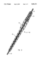
- FIG. 5 is a partially cut-away view taken along lines 5--5 of FIG. 4;
- FIG. 6. is an axial cross-sectional view taken along lines 6--6 of FIG. 5.
- the present invention is directed to a handpiece for use in connection with a surgical laser optical fiber terminating in an orbicular shaped contact tip, and an assembly of such a handpiece and fiber.
- FIG. 1 depicts one presently preferred embodiment of an optical fiber assembly, shown generally at 10, which includes a dressed optical fiber 12 and a handpiece 14.
- Handpiece 14 advantageously has a handle portion 16 having a diameter and a length suitable for comfortable use by a surgeon. A diameter of about 10 millimeters and a length of about 750 millimeters (about 3 inches) has been found adequate for most applications. Handle portion 16 must also be constructed of a material having sufficient strength to withstand the forces imposed by a surgeon's hand during use of the optical fiber assembly 10.
- the embodiment of FIG. 1 utilizes a handle portion 16 formed from a relatively rigid plastic material. As illustrated in FIG. 1, handle portion 16 is advantageously provided with ridges 18 in order to minimize the possibility of slippage as the surgeon manipulates the optical fiber assembly 10 during a surgical procedure.
- Extended portion 20 is preferably formed of a strong and relatively rigid material, such as stainless steel. This construction permits the application of force at the handle portion to be transmitted to the operating tip of the surgical laser. This is very useful not only during operation of the laser, at which time the application of mechanical force can substantially assist the surgeon in completing a surgical procedure, but also is of great value during insertion of the tip of the surgical laser past the various ligaments, tendons, and the like, which frequently overlie a surgical site.
- Extended portion 20 can be of any suitable length and diameter.
- the preferred length of the embodiment of FIG. 1, however, is about 17.78 centimeters (7 inches) for typical orthopedic procedures.
- the preferred outer diameter of the extended portion is about 2.11 millimeters in the illustrated embodiment, thereby facilitating relatively easy insertion and manipulation of the distal end of the optical fiber assembly within a surgical site.
- the inner diameter of the extended portion is preferably selected so as to hold the dressed optical fiber 12 within extended portion 20 in a loose friction fit.
- the distal tip of optical fiber assembly 10 is preferably formed into a generally spherical shape, sometimes referred to as being "orbicular.”
- Dressing 24 is preferably removed from the distal end portion of dressed optical fiber 12, leaving a short length of fiber 26 exposed.
- the presently preferred optical fiber 26 has a diameter of 1000 microns, although it will be readily appreciated by one of ordinary skill in the art that larger or smaller fibers could be used without departing from the spirit of the invention disclosed herein.
- the diameter of the orbicular tip 22 of the embodiment illustrated in FIG. 2 is preferably about 1200 microns.
- the proximal portion of orbicular tip 22 in the illustrated embodiment is partially retracted into extended portion 20. This configuration protects the tip from stresses which could break it off from the end of fiber 26.
- the embodiment of FIGS. 1 and 2 is adapted to virtually eliminate any possibility of breaking the orbicular tip off of fiber 26, while leaving the distal portion of orbicular tip 22 unobstructed for use in surgical procedures.
- the outside of the distal end of extended portion 20 is preferably chamfered, shown at 28 in FIG. 2.
- chamfering in the manner illustrated makes easier the insertion of the tip of optical fiber assembly 10 through and around various tissues during placement and manipulation of the assembly.
- collar 36 provides increased support at this juncture. If fitted tightly around the dressed optical fiber, collar 36 can also assist in affixing handpiece 14 to fiber 12, thereby helping maintain the proper orientation of orbicular tip 22 at the end of extended portion 20.
- the optical fiber assembly 10 of FIG. 1 is useful in any surgical procedure wherein cutting is to be accomplished at the very tip of the fiber.
- a suitable connector assembly 38 is used to interconnect the proximal end of the fiber optic 26 to a laser source (not shown).
- An incision is made at an appropriate location, such as at a knee joint, and the distal tip of the optical fiber assembly of the present invention is inserted through the incision.
- the tip is then manipulated around the various tendons and ligaments in order to reach, for example, a damaged piece of cartilage at a bone surface which requires repair,
- the present invention permits the surgeon to exercise great control over the placement of the surgical laser tip, and even the application of substantial force, without the risk that the tip will be broken off inside the patient.
- a source of liquid is injected into the surgical site under great pressure.
- This liquid serves two purposes. First, a significant amount of heat energy is generated during operation of the laser. Flushing the surgical site with a continuous flow of liquid serves to cool the surgical site, thereby preventing the temperature from climbing too high, and hence damaging healthy tissue at the surgical site. Second, injecting fluid into the surgical site under pressure serves to separate the overlying skin from underlying bone, muscle, tendons, and the like, thereby making easier the task of manipulating the tip of the surgical laser within the surgical field.
- Introducer 30 may advantageously be provided that significantly reduces this leakage problem, and also facilitates insertion of the optical fiber assembly through in incision site.
- Introducer 30 is preferably formed in two parts, a leading portion 32 and a trailing portion 34.
- leading portion 32 is formed from a semirigid plastic material. It has an inside diameter slightly greater than the extended portion 20 of handpiece 14, thereby permitting easy movement along the length of extended portion 20.
- Trailing portion 34 is preferably formed from a more elastic material, and is sized so as to fit in a relatively loose friction fit with extended portion 20 so that the introducer will remain in place unless some force is applied, whereupon the introducer will slide along the length of extended portion 20 of the handpiece.
- introducer 30 is preferably tapered so as to facilitate insertion thereof through an incision.
- introducer is advanced to the distal end of the optical fiber assembly, or even slightly past the end.
- the introducer is pushed through the incision, which should be small enough so that the introducer substantially plugs the incision opening when inserted.
- the extended portion is advanced to the incision site, and surgery is commenced.
- the relatively tight fit between the introducer and the incision on the outside, and the introducer and the extended portion of the handpiece on the inside substantially seals off any significant loss of cooling liquid. In cases where the introducer is unwanted, it is easily removed by simply sliding it off the end of the optical fiber assembly.
- FIG. 4 Another embodiment of the present invention is illustrated in FIG. 4. This embodiment not only depicts a second presently preferred embodiment of an optical fiber assembly in accordance with the present invention, but also demonstrates several of the types of changes which may be made without departing from the spirit and essential teachings of the invention. It should be understood, however, that other changes might also be made within the scope of the present invention.
- FIG. 4 illustrates an optical fiber assembly 110 comprised of an optical fiber 112 and a handpiece 114.
- Handpiece 114 includes a handle portion 116 and an extended portion 120.
- Handle portion 116 is preferably provided with ridges 118, and is sized and shaped for comfortable use by a surgeon.
- the presently preferred material for the handpiece of FIG. 4 is plastic, although it will be appreciated that stainless steel or other materials could be used.
- extended portion 120 may taper from a larger, and hence stronger, diameter 140 near the handle portion, to a narrower, and hence more easily inserted, diameter 142 near the tip of the optical fiber assembly.
- a narrow diameter at the tip also facilitates ease of vision at the surgical site.
- FIG. 6 illustrates the preferred situation wherein dressing 124 fits snugly within the narrower diameter portion 142 of extended portion 120. This construction serves the dual function of assisting to retain the fiber within the handpiece 114, and also supports the working end of tile fiber optic.
- the proximal end of handpiece is preferably provided with a collar 136 to secure handpiece 114 to the dressed optical fiber 112 and to protect optical fiber 112 from damage at the point where it enters the handpiece.
- FIGS. 4-6 utilizes a larger orbicular tip 122 than the tip of FIGS. 1-3.
- fiber optic 126 is 1000 microns in diameter, and the orbicular tip 122 is preferably 2000 microns in diameter, or even larger.
- Such a large tip is particularly susceptible to breakage, however, and breakage has been a significant problem prior to introduction of the present invention.
- the possibility of breakage of a large diameter tip 122 is minimized by retracting the tip against the end of extended portion 120 so that the tip is supported.
- the inner diameter of the distal opening of extended portion 120 is chamfered 144 so as to follow the contours of orbicular tip 122. This configuration further supports orbicular tip 122, and serves to center the tip without scoring it.
- FIG. 5 also illustrates that it may be advantageous in some circumstances to provide a bend 146 near the end of extended portion 120. Such a bend is useful because force applied by a surgeon manipulating the handle portion 116 is more easily directed away from the axis of handle portion 116. This can provide increased leverage and otherwise facilitate the performance of some types of surgical procedures.
Abstract
Description
Claims (10)
Priority Applications (1)
| Application Number | Priority Date | Filing Date | Title |
|---|---|---|---|
| US08/185,686 US5401271A (en) | 1992-02-12 | 1994-01-24 | Apparatus for supporting an orbicularly tipped surgical laser fiber |
Applications Claiming Priority (2)
| Application Number | Priority Date | Filing Date | Title |
|---|---|---|---|
| US07/835,196 US5282798A (en) | 1992-02-12 | 1992-02-12 | Apparatus for supporting an orbicularly tipped surgical laser fiber |
| US08/185,686 US5401271A (en) | 1992-02-12 | 1994-01-24 | Apparatus for supporting an orbicularly tipped surgical laser fiber |
Related Parent Applications (1)
| Application Number | Title | Priority Date | Filing Date |
|---|---|---|---|
| US07/835,196 Continuation US5282798A (en) | 1992-02-12 | 1992-02-12 | Apparatus for supporting an orbicularly tipped surgical laser fiber |
Publications (1)
| Publication Number | Publication Date |
|---|---|
| US5401271A true US5401271A (en) | 1995-03-28 |
Family
ID=25268886
Family Applications (2)
| Application Number | Title | Priority Date | Filing Date |
|---|---|---|---|
| US07/835,196 Expired - Lifetime US5282798A (en) | 1992-02-12 | 1992-02-12 | Apparatus for supporting an orbicularly tipped surgical laser fiber |
| US08/185,686 Expired - Fee Related US5401271A (en) | 1992-02-12 | 1994-01-24 | Apparatus for supporting an orbicularly tipped surgical laser fiber |
Family Applications Before (1)
| Application Number | Title | Priority Date | Filing Date |
|---|---|---|---|
| US07/835,196 Expired - Lifetime US5282798A (en) | 1992-02-12 | 1992-02-12 | Apparatus for supporting an orbicularly tipped surgical laser fiber |
Country Status (1)
| Country | Link |
|---|---|
| US (2) | US5282798A (en) |
Cited By (4)
| Publication number | Priority date | Publication date | Assignee | Title |
|---|---|---|---|---|
| US5897551A (en) * | 1990-03-23 | 1999-04-27 | Myriadlase, Inc. | Medical device for applying high energy light and heat for gynecological sterilization procedures |
| WO2002009609A1 (en) * | 2000-07-31 | 2002-02-07 | Brookhaven Science Associates | Slender tip laser scalpel |
| WO2002087457A1 (en) * | 2001-04-26 | 2002-11-07 | Ethicon Endo-Surgery, Inc. | Medical laser fiber optic cable having improved treatment indicators for bph surgery |
| US20040138761A1 (en) * | 2001-08-27 | 2004-07-15 | Stack Richard S. | Satiation devices and methods |
Families Citing this family (44)
| Publication number | Priority date | Publication date | Assignee | Title |
|---|---|---|---|---|
| US5282798A (en) * | 1992-02-12 | 1994-02-01 | Heraeus Surgical, Inc. | Apparatus for supporting an orbicularly tipped surgical laser fiber |
| US5755850A (en) * | 1992-09-24 | 1998-05-26 | Iowa State University Research Foundation | Method of making a surgical laser fiber from a monolithic silica titania glass rod |
| US5531739A (en) * | 1994-09-23 | 1996-07-02 | Coherent, Inc. | Method of treating veins |
| US5630809A (en) * | 1994-12-19 | 1997-05-20 | Connor; Christopher S. | Intraocular slit illuminator and method therefor |
| US5571099A (en) * | 1995-05-09 | 1996-11-05 | Pioneer Optics Company | Side firing probe |
| FR2734468B1 (en) * | 1995-05-22 | 1997-12-19 | Choukroun Pierre Louis | INSTRUMENT INTENDED FOR PER-OPERATIVE EXPLORATION AND EXTRACTION OF VARICES USING TRANSILLUMINATION OF VESSELS THROUGH TISSUES USING FIBER OPTIC WITH LATERAL DIFFUSION |
| US5868734A (en) * | 1995-11-29 | 1999-02-09 | Iowa State University Research Foundation, Inc. | Methods of using silica-titania clad fibers |
| IT1286551B1 (en) * | 1996-02-13 | 1998-07-15 | El En S R L | DEVICE AND METHOD FOR THE ELIMINATION OF ADIPOSE LAYERS THROUGH LASER ENERGY |
| US7655002B2 (en) * | 1996-03-21 | 2010-02-02 | Second Sight Laser Technologies, Inc. | Lenticular refractive surgery of presbyopia, other refractive errors, and cataract retardation |
| US6464693B1 (en) * | 2000-03-06 | 2002-10-15 | Plc Medical Systems, Inc. | Myocardial revascularization |
| US7238180B2 (en) * | 2003-10-30 | 2007-07-03 | Medicalcv Inc. | Guided ablation with end-fire fiber |
| EP1680039A1 (en) * | 2003-10-30 | 2006-07-19 | Medical Cv, Inc. | Apparatus and method for laser treatment |
| US7232437B2 (en) * | 2003-10-30 | 2007-06-19 | Medical Cv, Inc. | Assessment of lesion transmurality |
| US7238179B2 (en) * | 2003-10-30 | 2007-07-03 | Medical Cv, Inc. | Apparatus and method for guided ablation treatment |
| US20070073277A1 (en) * | 2005-09-16 | 2007-03-29 | Medicalcv, Inc. | Controlled guided ablation treatment |
| US20070073281A1 (en) * | 2005-09-16 | 2007-03-29 | Medicalcv, Inc. | Guided ablation with motion control |
| US20070073280A1 (en) * | 2005-09-16 | 2007-03-29 | Medicalcv, Inc. | End-fire guided ablation |
| US9545338B2 (en) * | 2006-01-20 | 2017-01-17 | Lensar, Llc. | System and method for improving the accommodative amplitude and increasing the refractive power of the human lens with a laser |
| US8262646B2 (en) | 2006-01-20 | 2012-09-11 | Lensar, Inc. | System and method for providing the shaped structural weakening of the human lens with a laser |
| US9889043B2 (en) * | 2006-01-20 | 2018-02-13 | Lensar, Inc. | System and apparatus for delivering a laser beam to the lens of an eye |
| US10842675B2 (en) * | 2006-01-20 | 2020-11-24 | Lensar, Inc. | System and method for treating the structure of the human lens with a laser |
| US7726320B2 (en) | 2006-10-18 | 2010-06-01 | R. J. Reynolds Tobacco Company | Tobacco-containing smoking article |
| ITFI20070221A1 (en) * | 2007-10-05 | 2009-04-06 | El En Spa | "DEVICE FOR USING ALSO A SINGLE USE OF AN OPTICAL FIBER FOR INVASIVE TREATMENT WITH LASER SURGERY IN THE HUMAN BODY" |
| US8480659B2 (en) | 2008-07-25 | 2013-07-09 | Lensar, Inc. | Method and system for removal and replacement of lens material from the lens of an eye |
| US20100022996A1 (en) * | 2008-07-25 | 2010-01-28 | Frey Rudolph W | Method and system for creating a bubble shield for laser lens procedures |
| US8500723B2 (en) * | 2008-07-25 | 2013-08-06 | Lensar, Inc. | Liquid filled index matching device for ophthalmic laser procedures |
| US8617146B2 (en) | 2009-07-24 | 2013-12-31 | Lensar, Inc. | Laser system and method for correction of induced astigmatism |
| CN102625685B (en) * | 2009-07-24 | 2015-11-25 | 能斯雅有限公司 | For the liquid storage interface equipment of ophthalmology laser surgery |
| EP2456384B1 (en) * | 2009-07-24 | 2023-09-20 | LENSAR, Inc. | System for providing laser shot patterns to the lens of an eye |
| US8758332B2 (en) * | 2009-07-24 | 2014-06-24 | Lensar, Inc. | Laser system and method for performing and sealing corneal incisions in the eye |
| EP2456385B1 (en) * | 2009-07-24 | 2015-07-22 | Lensar, Inc. | System for performing ladar assisted procedures on the lens of an eye |
| US8382745B2 (en) * | 2009-07-24 | 2013-02-26 | Lensar, Inc. | Laser system and method for astigmatic corrections in association with cataract treatment |
| WO2011094678A1 (en) | 2010-02-01 | 2011-08-04 | Lensar, Inc. | Purkinjie image-based alignment of suction ring in ophthalmic applications |
| WO2011094666A1 (en) * | 2010-02-01 | 2011-08-04 | Lensar, Inc. | Placido ring measurement of astigmatism axis and laser marking of astigmatism axis |
| US8757147B2 (en) | 2010-05-15 | 2014-06-24 | Minusa Holdings Llc | Personal vaporizing inhaler with internal light source |
| US11344683B2 (en) | 2010-05-15 | 2022-05-31 | Rai Strategic Holdings, Inc. | Vaporizer related systems, methods, and apparatus |
| USD695408S1 (en) | 2010-10-15 | 2013-12-10 | Lensar, Inc. | Laser system for treatment of the eye |
| USD694890S1 (en) | 2010-10-15 | 2013-12-03 | Lensar, Inc. | Laser system for treatment of the eye |
| CN106974614B (en) | 2010-10-15 | 2019-04-26 | 雷萨公司 | The system and method for the scan control illumination of the structure of inside of eye |
| US10463541B2 (en) | 2011-03-25 | 2019-11-05 | Lensar, Inc. | System and method for correcting astigmatism using multiple paired arcuate laser generated corneal incisions |
| US9078473B2 (en) | 2011-08-09 | 2015-07-14 | R.J. Reynolds Tobacco Company | Smoking articles and use thereof for yielding inhalation materials |
| US9393154B2 (en) | 2011-10-28 | 2016-07-19 | Raymond I Myers | Laser methods for creating an antioxidant sink in the crystalline lens for the maintenance of eye health and physiology and slowing presbyopia development |
| US9839238B2 (en) | 2014-02-28 | 2017-12-12 | Rai Strategic Holdings, Inc. | Control body for an electronic smoking article |
| US10034494B2 (en) | 2015-09-15 | 2018-07-31 | Rai Strategic Holdings, Inc. | Reservoir for aerosol delivery devices |
Citations (11)
| Publication number | Priority date | Publication date | Assignee | Title |
|---|---|---|---|---|
| US3865113A (en) * | 1972-10-17 | 1975-02-11 | Laser Ind Ltd | Laser device particularly useful as surgical scalpel |
| US4537193A (en) * | 1982-10-28 | 1985-08-27 | Hgm, Inc. | Laser endocoagulator apparatus |
| US4538609A (en) * | 1981-07-07 | 1985-09-03 | Sumitomo Electric Industries, Ltd. | Manipulator for laser knife |
| US4629450A (en) * | 1984-05-09 | 1986-12-16 | Terumo Corporation | Catheter introducing instrument |
| US4671273A (en) * | 1984-03-19 | 1987-06-09 | Lindsey Ernest J | Laser hand piece, for use in opthalmic, plastic, and ear, nose, and throat surgery |
| US4674499A (en) * | 1980-12-08 | 1987-06-23 | Pao David S C | Coaxial bipolar probe |
| US4693244A (en) * | 1984-05-22 | 1987-09-15 | Surgical Laser Technologies, Inc. | Medical and surgical laser probe I |
| US4950267A (en) * | 1987-11-27 | 1990-08-21 | Olympus Optical Co., Ltd. | Laser beam treatment device for an endoscope |
| US4966587A (en) * | 1988-04-29 | 1990-10-30 | Rainer Baumgart | Medical intromission kit |
| WO1991002562A1 (en) * | 1989-08-17 | 1991-03-07 | Surgical Laser Products, Inc. | Integral end structure for medical laser waveguide |
| US5282798A (en) * | 1992-02-12 | 1994-02-01 | Heraeus Surgical, Inc. | Apparatus for supporting an orbicularly tipped surgical laser fiber |
-
1992
- 1992-02-12 US US07/835,196 patent/US5282798A/en not_active Expired - Lifetime
-
1994
- 1994-01-24 US US08/185,686 patent/US5401271A/en not_active Expired - Fee Related
Patent Citations (11)
| Publication number | Priority date | Publication date | Assignee | Title |
|---|---|---|---|---|
| US3865113A (en) * | 1972-10-17 | 1975-02-11 | Laser Ind Ltd | Laser device particularly useful as surgical scalpel |
| US4674499A (en) * | 1980-12-08 | 1987-06-23 | Pao David S C | Coaxial bipolar probe |
| US4538609A (en) * | 1981-07-07 | 1985-09-03 | Sumitomo Electric Industries, Ltd. | Manipulator for laser knife |
| US4537193A (en) * | 1982-10-28 | 1985-08-27 | Hgm, Inc. | Laser endocoagulator apparatus |
| US4671273A (en) * | 1984-03-19 | 1987-06-09 | Lindsey Ernest J | Laser hand piece, for use in opthalmic, plastic, and ear, nose, and throat surgery |
| US4629450A (en) * | 1984-05-09 | 1986-12-16 | Terumo Corporation | Catheter introducing instrument |
| US4693244A (en) * | 1984-05-22 | 1987-09-15 | Surgical Laser Technologies, Inc. | Medical and surgical laser probe I |
| US4950267A (en) * | 1987-11-27 | 1990-08-21 | Olympus Optical Co., Ltd. | Laser beam treatment device for an endoscope |
| US4966587A (en) * | 1988-04-29 | 1990-10-30 | Rainer Baumgart | Medical intromission kit |
| WO1991002562A1 (en) * | 1989-08-17 | 1991-03-07 | Surgical Laser Products, Inc. | Integral end structure for medical laser waveguide |
| US5282798A (en) * | 1992-02-12 | 1994-02-01 | Heraeus Surgical, Inc. | Apparatus for supporting an orbicularly tipped surgical laser fiber |
Cited By (4)
| Publication number | Priority date | Publication date | Assignee | Title |
|---|---|---|---|---|
| US5897551A (en) * | 1990-03-23 | 1999-04-27 | Myriadlase, Inc. | Medical device for applying high energy light and heat for gynecological sterilization procedures |
| WO2002009609A1 (en) * | 2000-07-31 | 2002-02-07 | Brookhaven Science Associates | Slender tip laser scalpel |
| WO2002087457A1 (en) * | 2001-04-26 | 2002-11-07 | Ethicon Endo-Surgery, Inc. | Medical laser fiber optic cable having improved treatment indicators for bph surgery |
| US20040138761A1 (en) * | 2001-08-27 | 2004-07-15 | Stack Richard S. | Satiation devices and methods |
Also Published As
| Publication number | Publication date |
|---|---|
| US5282798A (en) | 1994-02-01 |
Similar Documents
| Publication | Publication Date | Title |
|---|---|---|
| US5401271A (en) | Apparatus for supporting an orbicularly tipped surgical laser fiber | |
| US5476461A (en) | Endoscopic light delivery system | |
| CA2193981C (en) | Self-centering valvulotome | |
| US6102905A (en) | Phototherapy device including housing for an optical element and method of making | |
| US6322499B1 (en) | Pivotal and illuminated saphenous vein retractor | |
| US20170231649A1 (en) | Medical systems and related methods | |
| US6652547B2 (en) | Apparatus and method of removing occlusions using ultrasonic medical device operating in a transverse mode | |
| AU694776B2 (en) | Apparatus and method for interstitial laser treatment | |
| US6574401B2 (en) | Optical fiber-handpiece combination for medical laser treatments | |
| US5944713A (en) | Method of treating a body cavity using an endoscopic surgical laser | |
| US9216049B2 (en) | Systems and methods for implant removal | |
| AU643889B2 (en) | Laser video endoscope | |
| US20040167503A1 (en) | Malleable surgical ablation instruments | |
| US5304172A (en) | Fiber optic probe | |
| US20090287197A1 (en) | Side-firing laser fiber with internal bent fiber and related methods | |
| AU2002235463A1 (en) | Method of removing occlusions using ultrasonic medical device operating in a transverse mode | |
| US20090287196A1 (en) | Laser energy devices and methods for soft tissue removal | |
| US20170042618A1 (en) | Disposable sleeve for protecting surgical laser delivery fiber assembly, and laser delivery fiber with metal tip | |
| US10842587B2 (en) | Method for minimally invasive surgery using therapeutic ultrasound to treat spine and orthopedic diseases, injuries and deformities | |
| US5549600A (en) | Surgical laser probe with thermal cutting | |
| IL154120A (en) | System and method for pulverizing stones and for scar removal in soft tissues | |
| CA2045064A1 (en) | Prosthetic joint replacement procedure using excimer laser | |
| Buehler et al. | Polymethylmethacrylate removal from the femur using a crescentic window technique | |
| US20100292681A1 (en) | Device for the use, also single use, of an optical fiber for invasive surgical laser treatment in the human body | |
| Ulrich et al. | A micromanipulator to aid microsurgical removal of intracranial tumours with the Nd-YAG laser |
Legal Events
| Date | Code | Title | Description |
|---|---|---|---|
| CC | Certificate of correction | ||
| AS | Assignment |
Owner name: HERAEUS SURGICAL, INC., FORMERLY KNOWN AS HERAEUS Free format text: ASSIGNMENT OF ASSIGNORS INTEREST;ASSIGNOR:HERAEUS SYSTEMS, INC., FORMERLY KNOWN AS HERAEUS LASERSONICS, INC., THEN KNOWN AS HERAEUS SURGICAL, INC.;REEL/FRAME:008077/0679 Effective date: 19960809 |
|
| AS | Assignment |
Owner name: LASERSCOPE, CALIFORNIA Free format text: MERGER;ASSIGNOR:HERAEUS SURGICAL, INC.;REEL/FRAME:008401/0392 Effective date: 19961206 |
|
| AS | Assignment |
Owner name: LASERSCOPE, CALIFORNIA Free format text: ASSIGNMENT OF ASSIGNORS INTEREST;ASSIGNOR:HERAEUS SURGICAL, INC.;REEL/FRAME:008454/0751 Effective date: 19960301 |
|
| AS | Assignment |
Owner name: SURGIMEDICS, INC., TEXAS Free format text: ASSIGNMENT OF ASSIGNORS INTEREST;ASSIGNOR:LASERSCOPE;REEL/FRAME:008709/0679 Effective date: 19970814 |
|
| FEPP | Fee payment procedure |
Free format text: PAYOR NUMBER ASSIGNED (ORIGINAL EVENT CODE: ASPN); ENTITY STATUS OF PATENT OWNER: LARGE ENTITY |
|
| REMI | Maintenance fee reminder mailed | ||
| FEPP | Fee payment procedure |
Free format text: PAYER NUMBER DE-ASSIGNED (ORIGINAL EVENT CODE: RMPN); ENTITY STATUS OF PATENT OWNER: LARGE ENTITY Free format text: PAYOR NUMBER ASSIGNED (ORIGINAL EVENT CODE: ASPN); ENTITY STATUS OF PATENT OWNER: LARGE ENTITY |
|
| LAPS | Lapse for failure to pay maintenance fees | ||
| FP | Lapsed due to failure to pay maintenance fee |
Effective date: 19990328 |
|
| AS | Assignment |
Owner name: SILICON VALLEY BANK, CALIFORNIA Free format text: SECURITY INTEREST;ASSIGNOR:LASERSCOPE;REEL/FRAME:010404/0394 Effective date: 19991129 |
|
| STCH | Information on status: patent discontinuation |
Free format text: PATENT EXPIRED DUE TO NONPAYMENT OF MAINTENANCE FEES UNDER 37 CFR 1.362 |