US5418875A - Adapter for optical connector having float-type sleeve holder and panel fitting for mounting the same - Google Patents
Adapter for optical connector having float-type sleeve holder and panel fitting for mounting the same Download PDFInfo
- Publication number
- US5418875A US5418875A US08/114,959 US11495993A US5418875A US 5418875 A US5418875 A US 5418875A US 11495993 A US11495993 A US 11495993A US 5418875 A US5418875 A US 5418875A
- Authority
- US
- United States
- Prior art keywords
- adapter
- panel
- fitting
- sleeve holder
- sleeve
- Prior art date
- Legal status (The legal status is an assumption and is not a legal conclusion. Google has not performed a legal analysis and makes no representation as to the accuracy of the status listed.)
- Expired - Fee Related
Links
- 230000003287 optical effect Effects 0.000 title claims abstract description 123
- 230000000295 complement effect Effects 0.000 claims description 12
- 230000003014 reinforcing effect Effects 0.000 claims description 8
- 210000002105 tongue Anatomy 0.000 claims 1
- 239000013307 optical fiber Substances 0.000 description 29
- 238000003466 welding Methods 0.000 description 5
- 238000004891 communication Methods 0.000 description 3
- 230000005540 biological transmission Effects 0.000 description 2
- 238000006073 displacement reaction Methods 0.000 description 2
- 239000000835 fiber Substances 0.000 description 2
- 238000003780 insertion Methods 0.000 description 2
- 230000037431 insertion Effects 0.000 description 2
- 238000000034 method Methods 0.000 description 2
- 229920003002 synthetic resin Polymers 0.000 description 2
- 239000000057 synthetic resin Substances 0.000 description 2
- 239000000463 material Substances 0.000 description 1
- 230000013011 mating Effects 0.000 description 1
- 238000012986 modification Methods 0.000 description 1
- 230000004048 modification Effects 0.000 description 1
- 230000002093 peripheral effect Effects 0.000 description 1
- 238000000926 separation method Methods 0.000 description 1
- 238000005476 soldering Methods 0.000 description 1
Images


Classifications
-
- G—PHYSICS
- G02—OPTICS
- G02B—OPTICAL ELEMENTS, SYSTEMS OR APPARATUS
- G02B6/00—Light guides; Structural details of arrangements comprising light guides and other optical elements, e.g. couplings
- G02B6/24—Coupling light guides
- G02B6/36—Mechanical coupling means
- G02B6/38—Mechanical coupling means having fibre to fibre mating means
- G02B6/3807—Dismountable connectors, i.e. comprising plugs
- G02B6/3897—Connectors fixed to housings, casing, frames or circuit boards
-
- G—PHYSICS
- G02—OPTICS
- G02B—OPTICAL ELEMENTS, SYSTEMS OR APPARATUS
- G02B6/00—Light guides; Structural details of arrangements comprising light guides and other optical elements, e.g. couplings
- G02B6/24—Coupling light guides
- G02B6/36—Mechanical coupling means
- G02B6/38—Mechanical coupling means having fibre to fibre mating means
- G02B6/3807—Dismountable connectors, i.e. comprising plugs
- G02B6/381—Dismountable connectors, i.e. comprising plugs of the ferrule type, e.g. fibre ends embedded in ferrules, connecting a pair of fibres
- G02B6/3825—Dismountable connectors, i.e. comprising plugs of the ferrule type, e.g. fibre ends embedded in ferrules, connecting a pair of fibres with an intermediate part, e.g. adapter, receptacle, linking two plugs
-
- G—PHYSICS
- G02—OPTICS
- G02B—OPTICAL ELEMENTS, SYSTEMS OR APPARATUS
- G02B6/00—Light guides; Structural details of arrangements comprising light guides and other optical elements, e.g. couplings
- G02B6/24—Coupling light guides
- G02B6/36—Mechanical coupling means
- G02B6/38—Mechanical coupling means having fibre to fibre mating means
- G02B6/3807—Dismountable connectors, i.e. comprising plugs
- G02B6/3873—Connectors using guide surfaces for aligning ferrule ends, e.g. tubes, sleeves, V-grooves, rods, pins, balls
- G02B6/3874—Connectors using guide surfaces for aligning ferrule ends, e.g. tubes, sleeves, V-grooves, rods, pins, balls using tubes, sleeves to align ferrules
- G02B6/3875—Floatingly supported sleeves
-
- G—PHYSICS
- G02—OPTICS
- G02B—OPTICAL ELEMENTS, SYSTEMS OR APPARATUS
- G02B6/00—Light guides; Structural details of arrangements comprising light guides and other optical elements, e.g. couplings
- G02B6/24—Coupling light guides
- G02B6/36—Mechanical coupling means
- G02B6/38—Mechanical coupling means having fibre to fibre mating means
- G02B6/3807—Dismountable connectors, i.e. comprising plugs
- G02B6/3898—Tools, e.g. handheld; Tuning wrenches; Jigs used with connectors, e.g. for extracting, removing or inserting in a panel, for engaging or coupling connectors, for assembling or disassembling components within the connector, for applying clips to hold two connectors together or for crimping
Definitions
- the present invention relates to an adapter for the optical connector for connecting optical fibers and, in particular, to an adapter for the optical connector comprising a pair of adapter elements which face to each other and a sleeve holder having an alignment sleeve therein, which is disposed between the adapter elements and a panel fitting for securing the adapter to a panel for wiring optical fibers of communication lines by a single operation.
- Optical connectors are adapted to connect optical fibers by positioning the optical fibers in the center of cylindrical ferrules and inserting the ferrules into a hollow cylindrical alignment sleeve having precisely manufactured inner diameter to abut the terminal of the ferrule on the terminal of the other ferrule.
- the alignment sleeve has been heretofore loosely fitted in a pair of sleeve holders which are identical in shape.
- the sleeve holders are not press fitted or not bonded to each other, but may be slightly moved independently of each other and is loosely fitted in a pair of housings.
- the housings are secured to each other by various methods such as screwing,caulking, ultrasonic welding to form an adapter for the optical connector. Examples of the securing methods are as follows:
- FIGS. 29(a) and 29(b) show an adapter for the optical connector which connects a pair of optical fibers by conventional screwing.
- the adapter 10 has a pair of housings 11. Each housing 11 has a flange 11a adjacent to the abut face thereof. The flange 11a of one housing 11 is formed with a screw through-hole and the flange 11a of the other housing 11 is formed with a threaded hole. Both housings are fastened to each other by two screws 12.
- a sleeve holder 13 is loosely fitted in each of tile housings 11.
- An alignment sleeve 14 extends through a pair of the sleeve holder 13.
- the alignment sleeve 14 is formed with a fine slit(not shown) which extends in an axial direction.
- the ferrules of the plugs which are attached to the terminals of the optical fibers inserted into the alignment sleeve 14 from the opposite sides thereof.
- a clearance 15 is provided between the sleeve holders 13 and the alignment sleeve 14. Accordingly, even if the ferrules are inserted into the alignment sleeve 13 in a misalignment manner, the alignment sleeve 14 can bring two ferrules into an alignment relation within the clearance 15.
- a reinforcing member (not shown) which is called as plug housing is generally provided along the periphery of the ferrule in order to prevent the misalignment of the ferrules from occurring in the above mentioned adapter. Even if a torsional force which is normal to the axis of the plug is applied to the plug, the force could be absorbed by the pair of housings 11 to some extent. Even if a force which is larger to tilt the ferrules is applied, the alignment sleeve 14 and the ferrules could be correspondingly displaced within the clearance 15. This maintains the contact between the terminals of the optical fibers so that any losses of light will not take place.
- the above mentioned adapter 10 for the optical connector can be mounted on an external device such as a panel P for wiring optical fibers of communication lines and the like by means of screws which are screwed into screw holes best shown in FIG. 29(a) where screws 12 are not shown.
- FIGS. 30(a) and 30(b) show an adapter for the optical connector for connecting a pair of optical fibers which is assembled by conventional caulking.
- the adapter 20 includes a pair of housings 21.
- Each housing 21 has a flange 21a adjacent to the abut face which abuts on the abut face of the other housing 21.
- the flange 21a of each housing 21 is formed with a through-hole 21b through which a caulking ring extends.
- a spot facing 21c is formed in the vicinity of the exit of the caulking ring through-hole 21b.
- the caulking ring 22 has a flange at only one end as shown in FIGS. 32(a) and 32(b).
- the caulking ring 22 which is shown in FIGS. 32(a) and 32(b) is inserted into the aligned caulking ring through-holes 21b of the flanges 21a which abut to each other as shown in FIG. 30(b) and then the ring 22 is caulked. This causes both housings 21 to be fastened to each other.
- the sleeve holders 23 and the alignment sleeve 24 are fitted to the pair of housings 21 generally similarly to the sleeve holders 13 and the alignment sleeve 14 shown in FIG. 29(a).
- the above mentioned adapter 20 for the optical fiber connector is mounted on a panel by means of panel fitting 25 with springs 25a, which are adapted into the opposite sides of either housing 21.
- FIGS. 33(a) to 33(c) show an adapter for the optical connector which is assembled by ultrasonic welding.
- the adapter 30 has a pair of housings 31.
- Each housing 31 has flanges 31a adjacent to the abut face which abuts on face of the other housing 31.
- the flanges 31a of each housing 31 are formed with screw through holes 31b to which screws are inserted for securing the adapter to the panel P.
- the abut faces of the flanges 31a are formed with various concaves and convexes which facilitate precision positioning and connection of both housings 31 by ultrasonic welding.
- the sleeve holder 33 and the alignment sleeve 34 are substantially identical in structure to the sleeve holders 13 and the alignment sleeve 14 shown in FIGS. 29(a) and 29(b), respectively and are fitted in the pair of housings 31 in the same manner as the holders 13 and the sleeve 14.
- the sleeve holders 33 are loosely fitted in the housings 31 and the alignment sleeve 34 is inserted into a pair of sleeve holder so that it extends therethrough. Then, the abut faces of the pair of housings 31 are exposed to ultrasonic waves to be welded.
- the adapter 30 is mounted on a panel P by means of screws (not shown) which extend through screw holes 31b which are formed through the flanges 31a of the housing 31.
- FIGS. 34(a), 34(b) and FIG. 35 Other structures for mounting an adapter for the optical connector on an external device such as a panel for wiring optical fibers of communication lines are shown in FIGS. 34(a), 34(b) and FIG. 35.
- the adapter 40 has engaging recess 41c extending from the upper faces 41a of the housings 41 to the both sides 41b.
- a panel fitting 42 having an external shape which is complementary to the engaging recess 41c is fitted therein.
- the panel P is sandwiched between the flanges 41d of the housing 41 and the spring piece 42a of the panel fitting 42 so that the adapter 40 is secured to the panel P.
- FIG. 35 shows a panel fitting for securing an adapter to a circuit board type panel P.
- the optical connectors are adapted to connect a pair of optical fibers which are positioned in both sides of the panel P.
- FIG. 35 a pair of optical fibers which are positioned in one side of a panel P are connected by the optical fiber connector.
- a panel fitting 46 has an L-shape.
- An upright portion 46a of the fitting 46 is secured to an adapter 45 by fastening means 47.
- a base portion 46b is secured to the panel P by screwing or soldering.
- any conventional adapters require a special tool or facility to secure a pair of housings. Some of them require additional parts for securing the adapter.
- the adapters which are screwed require screws which are turned by screw drivers.
- the adapters which are caulked require caulking rings and caulking is carried out by a press and a caulking jig.
- Ultrasonic welding requires an expensive ultrasonic wave generator and a positioning jig. In any cases, it takes an extended period of time to complete a housing securing working.
- the size of the whole adapter is large and the size of the lateral section which is normal to the axial direction is about 1.5 to 2 times as large as that of the adapter having no flanges.
- the pair of housings are secured to each other so that they will not be displaced. Since the pair of sleeve holders in the housings are independent of each other, they are mounted in such a manner that displacement between them may slightly occur.
- the adapters shown in FIGS. 29 to 34 have flanges for securing a pair of housings. When these adapters are inserted through the panels for mounting, the flanges are brought into an abutment on one side of a panel and are secured thereto by screwing or using panel fittings 25 and 42 shown in FIGS. 30 and 34, respectively. Since the flanges are larger than the panel fittings, the mounting density does not increase.
- the conventional adapters as shown in FIG. 35 are to be secured to the panel P, screws holes of flanges are also used for securing it to the panel fitting which is to be mounted on the panel as shown in FIG. 35. In this case, the flanges are large in size, resulting in a large mounting space.
- an adapter for an optical connector including first and second identical or non-identical adapter elements which are opposed to each other and a sleeve holder having an alignment sleeve therein which is sandwiched between both adapter elements, wherein each of adapter elements has engaging means which is snap-engaged with that of the other adapter element for securing both adapter elements.
- an adapter for an optical connector for securing first and second adapter elements in an opposing relationship, wherein the abut faces of both adapter elements are formed with press fit holes, said adapter elements being linked to each other by inserting reinforcing pins into the opposing press fit holes.
- an adapter for an optical connector including first and second adapter elements which are opposed to each other and a sleeve holder having an alignment sleeve therein which is sandwiched therebetween, wherein each adapter element has a seat which is in contact with part of the sleeve holder for sandwiching said sleeve holder between the seats, the sleeve holder has a pair of metallic sleeve holder elements, one of the sleeve holder elements being press fitted to the other sleeve holder element so that it will not be moved relative to the other sleeve holder element, the sleeve holder has on the periphery thereof in the intermediate position along the length thereof a flange which is complimentary in shape with the seat of each adapter element.
- an adapter for an optical connector which is secured to a panel by means of panel fitting in which said adapter has projections for securing the panel fitting on opposite two sides of the adapter main body which are normal to the faces on which openings are formed.
- a panel fitting for securing an adapter for an optical connector to a panel having an opening to which the adapter for the optical connector is inserted for mounting in which said panel fitting has a pair of reversed U-shaped plate members which are combined to sandwich the adapter; and each plate member including securing means for holding and securing the adapter and securing portions which are secured to the panel.
- a panel fitting for securing an adapter for an optical connector on a surface of the panel comprising: holding means for holding and securing the adapter; and securing portions disposed at one ends thereof which are secured to the panel.
- an adapter for an optical connector comprising a versatile securing means to which either of the panel fittings, a panel fitting which is inserted into the panel and secured thereto or a panel fitting which is secured to a surface of a panel can be secured.
- the pair of the adapter elements are assembled and secured.
- the engaging means are snap engaged with each other merely by facing and moving a pair of opposite adapter elements close to each other. This causes the adapter for the optical connector to be easily and firmly assembled and secured to each other, resulting in a remarkable reduction in assembly time.
- the reinforcing pin is inserted into press fit holes which are formed on the abut faces of the first and second adapter elements.
- Most of the adapter elements are generally made of a synthetic resin. If the strength of securing the first and second adapter elements by snap engagement is insufficient, reinforcing pins compensates for the strength. Combination of snap engagement and the linkage by the reinforcing pins enables the pair of adapter elements to be positively secured.
- the sleeve holder having the alignment sleeve is movably sandwiched between the pair of the adapter elements. Accordingly, the torsional force applied to the plug will not be directly applied to the alignment sleeve and the ferrule. Since the sleeve holder are tilted to follow the movement of the plug, the alignment sleeve and the ferrules positioned in the sleeve holder are less influenced.
- the pair of the sleeve holder elements which form an outer shell of the sleeve holder are secured so that they are not moved to each other, the clearance between the sleeve holder and the alignment sleeve will not become small. Accordingly, even if the ferrules are tilted in a given range, contact between the terminals of the optical fibers and alignment of the axes of the ferrules is maintained. This enables the optical fibers to be connected to each other without attenuating the transmission of light in the position of the adapter.
- the adapter main body is formed with projections for securing the panel fitting on two sides which are normal to faces where openings are formed.
- the adapter can be secured to or inserted therethrough and secured thereto by fitting the panel fitting to the projections.
- the adapter is sandwiched between a pair of reversed U-shaped plate members of the panel fitting and is secured to the panel fitting by securing means. Accordingly, the adapter is firmly secured to the panel fitting.
- Two opposite sides of the panel fitting secured to the periphery of the adapter are provided with projections and spring pieces or screw holes, by which the adapter is firmly secured to the panel.
- the adapter is sandwiched and secured by a panel fitting comprising a pair of reversed U-shaped member, or alternatively press-inserted or engaged and secured by a panel fitting comprising two L-shaped members.
- the securing portion of the panel fitting for the panel is provided with the spring hooks which can be elastically inserted and secured to the mounting hole of the panel or screw holes.
- the adapter can be secured to the surface of the panel by the spring hooks or screws extending through the screw holes.
- the adapter is formed on two sides with projections in one or two positions. If the projection is provided in one position, the projection has channels on both sides. This enables either of the panel fittings according to the fifth and sixth aspects to be mounted on one adapter of the optical connector.
- FIGS. 1(a) and 1(b) are an exploded perspective view of one embodiment of an adapter for the optical connector of the present invention and a perspective view showing an adapter for the optical connector which has been assembled, respectively;
- FIG. 2 is a schematic front elevational view partly in section showing the adapter of optical connector comprising a pair of adapter elements which are secured to each other by means of reinforcing pins;
- FIGS. 3(a), 3(b), 3(c) and 3(d) are plan, front, rear and right side elevational views, respectively, showing an adapter element which is part of the adapter of FIGS. 1(a) and 1(b);
- FIG. 4 is a longitudinal sectional view taken along the line A--A in FIG. 1(b);
- FIG. 5 is an exploded perspective view showing another embodiment of the adapter for the optical connector of the present invention.
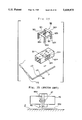
- FIG. 6 is a plan view showing a further embodiment of the adapter for the optical connector of the present invention.
- FIG. 7 is a plan view showing a further embodiment of the adapter for the optical connector of the present invention.
- FIG. 8 is a front view half in section showing a sleeve holder shown in FIG. 1(a) and 1(b);
- FIG. 9 is an exploded perspective view of a panel fitting for the present invention which is used for securing the adapter of the optical connector to the panel;
- FIG. 10 is a perspective view showing the panel fitting of FIG. 9 which is secured to the adapter for the optical connector;
- FIG. 11 is an elevational view showing the adapter for the optical connector which is secured to the panel by means of the panel fitting which is shown in FIGS. 9 and 10;
- FIG. 12 is a plan view of the adapter for the optical connector shown in FIG. 11;
- FIG. 13(a) is an exploded perspective view showing another panel fitting of the present invention which is used for securing the adapter for the optical connector to the panel;
- FIG. 13(b) is a perspective view showing the panel fitting of FIG. 13(a) which is secured to the adapter for the
- FIG. 14 is a perspective view showing a further embodiment of a which is used for securing the adapter for the optical connector to the panel;
- FIG. 15 is an exploded perspective view showing a further embodiment of the panel fitting of the present invention which is used for securing the adapter for the optical connector to the panel;
- FIG. 16 is a perspective view showing the panel fitting of FIG. 15 which is secured to the adapter for the optical connector;
- FIG. 17 is a perspective view showing a further embodiment of the panel fitting of the present invention and the manner in which a plug is inserted into the connector by using a plug inserter/remover;
- FIG. 18 is a longitudinal sectional view showing an embodiment of the assembled panel fitting and the adapter for the optical connector
- FIG. 19 is a longitudinal sectional view showing a further embodiment of the assembled panel fitting and the adapter for the optical connector
- FIG. 20 is an exploded perspective view showing a further embodiment of the panel fitting of the present invention which is used for securing the adapter for the optical connector to the panel;
- FIG. 21 is a perspective view showing the panel fitting of FIG. 20 which is secured to the adapter for the optical connector;
- FIG. 22 is a sectional view showing the adapter for the optical connector which is secured to the panel by means of the panel fitting of FIG. 21;
- FIG. 23 is an exploded perspective view showing a further embodiment of the panel fitting of the present invention which is used for securing the adapter for the optical connector to the panel;
- FIG. 24 is a sectional view showing the adapter for the optical connector which is secured to the panel by means of the panel fitting of FIG. 23;
- FIG. 25 is an exploded perspective view showing a further embodiment of the panel fitting of the present invention which is used for securing the adapter for the optical connector to the panel;
- FIG. 26 is an exploded perspective view showing a further embodiment of the panel fitting of the present invention which is used for securing the adapter for the optical connector to the panel;
- FIG. 27 is a perspective view showing a way in which the panel fitting of the present invention is used.
- FIG. 28 is a perspective view showing another way in which the panel fitting of the present invention is used.
- FIGS. 29(a) and 29(b) are plan view and a front view half in section, respectively, showing an adapter for the optical connector which is assembled by conventional screwing for connecting a pair of optical fibers;
- FIGS. 30(a) and 30(b) are plan view and a front view half in section, respectively, showing an adapter for the optical connector which is assembled by conventional caulking for connecting a pair of optical fibers;
- FIGS. 31(a) and 31(b ) are plan and longitudinal sectional views, respectively, showing the periphery of the flanges of the housings which are used in the adapter of FIG. 30;
- FIGS. 32(a) and 32(b) are plan and half sectional and front view, respectively, showing a caulking ring which is used in the adapter of FIG. 30.
- FIGS. 33(a) to 33(c) are plan, front view half in section showing an adapter for the optical connector which is assembled by conventional ultrasonic welding, and a bottom view showing an abutting surface of a housing, respectively;
- FIGS. 34(a) and 34(b) are perspective and elevational views, respectively, showing another structure for securing the adapter for the optical connector to an optical fiber wiring panel;
- FIG. 35 is a perspective view showing a further structure for securing the adapter for the optical connector to an optical fiber wiring panel.
- FIGS. 1(a) and 1(b) there are shown an exploded perspective view of an embodiment of an adapter for the optical connector of the present invention and a perspective view of the adapter of FIG. 1(a) which has been assembled.
- the adapter for the optical connector is of the type which connects a pair of optical fiber terminals in with each other.
- the adapter generally comprises a metallic sleeve holder 50, and a pair of adapter elements 60 made of synthetic resin.
- the sleeve holder 50 is loosely sandwiched between the adapter elements 60.
- holes 60a are formed on the abut faces of the first and second adapter elements 60. Both adapter elements may be linked to each other by pressure inserting metallic reinforcing pins 68 into opposing holes 60a. This provides a sufficient linkage strength when both adapter elements 60 are secured to each other by a snap engaging means which will be described hereafter. This pin and hole linking structure is effective particularly when the snap engaging means can not be provided with a sufficient structural strength.
- the elements could be linked to each other by only the pressure insertion of the metallic pressure insertion pins into the holes and snap engaging means may be structually omitted.
- each of the adapter elements 60 includes a housing 61 having a hollow rectangular tube-like shape.
- the housing 61 is formed therein with a space 61a to which a plug which will be attached to the terminal of the optical fibers is inserted.
- the housing 61 has two pairs of opposing sides 61c and 61d which are perpendicular to the abut face 6lb which will abut upon that of the other opposing housing 61.
- Each of the sides 61c is formed with a leaf elastic engaging piece 62 which projects in an inserting direction toward the opposite housing 61.
- Each of the sides 61c is formed with a recess 63 which accepts the elastic engaging piece 62 of the other adapter element 60.
- the elastic engaging piece 62 has a shape which is complementary to that of the recess 63. Accordingly, when the elastic engaging piece 62 of one of the adapter elements 60 is inserted into the recess 63 of the other adapter element 60, the piece 62 is flush with the corresponding side of the other element.
- This structure enables the pair of the adapter elements to eliminate a play in a direction normal to the inserting direction when the elastic engaging piece 62 of one adapter element 60 is inserted into the recess 63 of the other adapter element 60.
- the elastic engaging piece 62 is formed with a square-shaped engaging recess 62a in the vicinity of the front end thereof and the recess 63 is formed on the bottom thereof with an engaging protuberance 63a which will be inserted in the square engaging recess 62a of the elastic engaging piece 62.
- the ferrules of plugs attached to the terminals of optical fibers are generally pressed at a force of 6N (0.6 kgf) per ferrule by means of spring.
- the terminals of the fibers can be brought into firm contact with each other also in this case.
- the dimensions such as length and thickness of the leaf elastic engaging piece 62 are chosen depending upon its material so that the piece 62 can be elastically deformed beyond the engaging protuberance 63a of the recess 63 without being broken.
- the adapter element 60 is further formed with a leaf elastic engaging piece 64 which projects from the other side 61d in an inserting direction and the other adapting element 60 is formed on the corresponding side 61d thereof with a recess 65 to which the elastic engaging piece 64 of the adapter 60 is fitted.
- the recess 65 and the elastic engaging piece 64 are respectively formed with an engaging recess 65a and an engaging protuberance 64a, which engages with each other when both adapter elements 60 are inserted to each other.
- Each of the sides 61d is formed with a pair of ribs 67 on two positions thereof for engaging with a panel fitting which will be described hereafter.
- the abut faces of the engaging recess 65a and the engaging protuberance 64a which are in contact with each other are slightly inclined at an angle ⁇ in a biting direction with respect to a face normal to the surface of the elastic engaging piece 64 as illustrated in FIG. 4 in an exaggerated manner. This prevents the engaging protuberance 64a from disengaging from the engaging recess 65a since the engaging protuberance 64a will bite the contact face of the engaging recess 65a even if a force will act on the pair of the adapter elements 60 to separate them away from each other once the engaging protuberance 64a has been engaged with the engaging recess 65a.
- connection between the elastic engaging piece 64 and the housing 61 is positioned on the more inner side of the housing 61 in comparison with the elastic engaging piece 62. Accordingly, the length of the elastic engaging piece 64 which extends beyond the abut face 61b is about half of the elastic engaging piece 62.
- the recess 65 and the elastic engaging piece 64 on the respective sides 61d are provided to make the connection of the pair of adapter elements more firm even when the adapter is made more compact and may be in the various shapes other than the illustrated shape.
- the abut face 61b of the housing 61 is provided with a pair of stepped and circle seats 66 which extends into the inside of the housing 61.
- FIG. 5 there is shown another embodiment of an adapter for the optical connector of the present invention.
- the adapter for the optical connector in this embodiment is adapted to connect two pairs of optical fibers with each other.
- Each of the adapter element 70 has a rectangular tube-like housing 71 and is formed therein in a parallel relationship two spaces 71a into which two plugs attached to optical fiber terminals are inserted, respectively.
- the housing 71 has a pair of opposite sides 71c and a pair of opposite sides 71d which are normal to an abut face 71b which will abut on an abut face 71b of the other housing 71.
- Each side 71c is formed with two leaf elastic engaging pieces 72 which project in an inserting direction toward the opposite housing 71 in a parallel relationship with each other.
- One of the elastic engaging pieces 72 is shifted in a downward or thickness direction by a thickness of the piece 72 relative to the other elastic engaging piece 72.
- Each side 71a is formed on the upper and lower surfaces thereof with two recesses 73 which accepts elastic engaging pieces 72 of the other adapter element 70 which are formed in parallel relationship. Since the two elastic engaging pieces 72 are shifted in a depth direction, two recesses are correspondingly shifted.
- the recess 73 on one housing 71 is complimentary with the elastic engaging piece 72 of the other housing 71 in shape.
- an outer side elastic engaging piece 72 of one adapter element 70 is inserted into the upper recess 73 of the other adapter element 70, the upper sides 71c of the housings 71 are flush with each other.
- the outer side elastic engaging piece 72 is formed with a square shaped engaging recess 72a in the vicinity of the front end thereof.
- the upper recess 73 is formed on the bottom thereof with an engaging protuberance 73a which will engaged with the engaging recess 72a of the outer side elastic engaging piece 72 of the opposite adapter element 70.
- the inner side elastic engaging piece 72 is formed with a square shaped engaging protuberance 72b in the vicinity of the tip end thereof.
- the lower recess 73 is formed with an engaging recess 73b which will be engaged with the square shaped elastic engaging protuberance 72b of the inner side elastic engaging piece 72 of the other adapter element 70.
- the engaging recesses 72a are engage with the engaging protuberance 73a and the engaging protuberance 72b are engaged with the engaging recesses 73b in total 8 positions when a pair of adapter elements 70 are inserted to each other.
- Each of the sides 71d is formed in one position with a projection 74 for engaging a panel fitting which will be described hereafter.
- Each projection 74 is formed with a channel 74a in the side apart from the mating side 71b. Total 4 channels 74a are formed on both sides 71d of the housing 71.
- FIGS. 6 and 7 a further embodiment of an adapter for the optical connector which connects 8 pairs of optical fibers.
- the adapter shown in FIGS. 6 and 7 is substantially identical with the adapter shown in FIGS. 1 and 5 except that the former has a repeated pattern of the latter in a width direction.
- FIG. 8 The sleeve holder 50 shown in FIG. 1 is illustrated in detail.
- the sleeve holder 50 generally comprises an alignment sleeve 54 and a pair of sleeve holder elements 53 into which the alignment sleeve 54 is loosely fitted with a slight clearance 57.
- the sleeve holder 50 is formed with a stepped flange 56 along the periphery thereof in an intermediate position along the length thereof.
- the stepped flange 56 is complementary with the pair of the stepped circle seats 66 formed in the inside of each housing 61, Accordingly, when the pair of the adapter elements 60 are inserted to each other, the sleeve holder 50 is loosely fitted between the stepped seats 66 as shown in FIG. 4.
- ferrules which are inserted into the sleeve holder 50 is tilted, they could be moved in the clearance between the alignment sleeve 54 and the sleeve holder 53 so that separation and misalignment between the terminals of the ferrules can be prevented, If a torsional force is applied upon the plug in a direction normal to the axial direction thereof, the sleeve holder can follow the tilting of the plug since the sleeve holder 50 is loosely fitted in the adapter elements
- Such a structure is effective particularly for adapters for high density mountable and small size optical connector in which a large clearance can not be provided between the alignment sleeve and the sleeve holder.
- FIGS. 9 to 19 show a panel fitting 82 for inserting and securing an adapter for the optical connector to an opening formed in a panel (hereinafter referred to as "an insert type panel fitting")
- FIGS. 20 to 26 show a panel fitting 92 for securing an adapter for the optical connector to a surface of a panel. (hereinafter referred to as "a surface mount type panel fitting").
- the adapters are classified into two types; the first type is an adapter having on one side thereof one engaging projection such as the engaging projection 74 shown in FIGS. 5 to 7, the engaging projection such as engaging projection 81b and the engaging projection 91a shown in FIGS. 20 to 24 and the second type is an adapter on one side having two projections such as the engaging projections 67 shown in FIGS. 1 to 3 and the engaging projections 81b shown in FIG. 19 and the engaging projections 91a shown in FIG. 26.
- the first type is an adapter having on one side thereof one engaging projection such as the engaging projection 74 shown in FIGS. 5 to 7, the engaging projection such as engaging projection 81b and the engaging projection 91a shown in FIGS. 20 to 24
- the second type is an adapter on one side having two projections such as the engaging projections 67 shown in FIGS. 1 to 3 and the engaging projections 81b shown in FIG. 19 and the engaging projections 91a shown in FIG. 26.
- the adapter for the optical connector (hereinafter referred to as "adapter body") of one kind can be secured to the panel in both manners of mounting, i. e. an insert mounting and a surface mounting.
- the present invention has an advantage that the adapter body has versatility by provision of such projection(s) on the side of the adapter.
- This panel fitting is used for optical connector adapters which connect a pair of optical fibers which are positioned on both sides of a panel which is in an erecting position.
- FIGS. 9 to 12 there is shown an embodiment of such a panel fitting.
- the panel fitting 82 comprises a pair of plate members 82a which sandwich an adapter 81 therebetween.
- the plate members 82a are identical with each other in shape and dimension.
- Each plate member 82a comprises a base 82b which faces an upper or lower side of the adapter 81 and a pair of sides 82c which are formed integrally with both edges of the base 82b.
- the base 82b has two aligned projections 82d which abut on the side P1 of a panel P, and a wide spring piece 82e which is formed in a position opposite to the projections 82d and abuts on the opposite side P2 of the panel P.
- the spacing B between the projections 82d and the spring piece 82e is slightly larger than the thickness A of the panel P (refer to FIGS. 11 and 12).
- the sides 82c are formed with fitting recesses 82f for receiving rectangular engaging projections 81b on opposite two sides of the adapter 81.
- the fitting recesses 82f are rectangular holes which are complimentary with the rectangular engaging projections 81b formed on the sides of the adapter 81. Accordingly, if the reversed U-shaped plate members 82a are pressed into the upper and lower surfaces of the adapter 81, a pair of sides 82c are elastically expanded outwardly and then the engaging projections 81b of the adapter 81 are fitted into the fitting recesses 82f and the sides 82c are returned inwardly to original positions.
- each side 82c is formed with a projection 82i on the distal end thereof and the base 82b is formed in corresponding position with a hole 82j for receiving the projection 82i. Since the projection 82i is fitted into the hole 82j when the upper and lower plate members 82a are inserted to each other, movement of each plate member in an X direction in FIG. 9 is restricted. Accordingly, the plate members 82a are firmly secured to the adapter 81.
- a torsional force that is, a moment (in a direction of M in FIG. 10) is applied to the adapter 81, the force is absorbed by the insert portion between the projection 82i and the hole 82j.
- the force which is directly applied to the adapter 81 advantageously becomes less.
- the engaging projection 81b may be press fitted into the fitting recess 82f.
- the projections 82d of the base 82b and the spring piece 82e are formed by cutting and erecting part of the plate member 82a.
- the projections 82d are projected substantially normal to the plate member 82a.
- the spring piece 82e extends from the plate member 82a outwardly in an inclined manner and elastically abuts upon the other face P2 of the panel P.
- FIGS. 15 and 16 there is shown an alternative of a panel fitting for inserting into and securing the adapter of the present invention to a panel.
- each plate member 82a is formed on one side 82c with an engaging recess 82f which is identical with that of the foregoing embodiment and is formed on the other side 82c with a pair of hooking pawls 82g for elastically holding the both edges of the engaging projections 81b of the adapter 81.
- the pair of hooking pawls 82g are formed by cutting fine slits in the side 82c and are elastically held from the side 82c in a cantilever manner.
- the plate member 82a in FIG. 15 can be firmly secured to the adapter 81. If the plate member 82a can be firmly secured to the adapter 81 against the moment M, the projection 82i and holes 82j may be omitted.
- FIG. 17 there is shown a further embodiment of the panel fitting of the present invention.
- the illustrated panel fitting 82 is substantially identical with the panel fitting shown in FIGS. 15 and 16 except that a number of grooves 82k are formed along the edge of the plate member 82a. Accordingly, the same or similar components are represented by the same reference numerals.
- the panel fitting 82 is used in combination with a plug inserter/remover 83 having a pair of guides 83a.
- the pair of guides 83a of the plug inserter remover 83 is inserted into a predetermined groove 82k of the panel fitting 82 to link therewith. Thereafter, a main body 83b of the inserter/remover 83 which holds the plug 84 is slid to a predetermined position of a pair of elastic pawls of the adapter. This causes a pair of elastic pawls to snap engage with engaging portions 84a formed on the opposite sides of the plug 84 so that the plug 84 is linked to the adapter.
- the pair of the guides 83a of the plug inserter/remover 83 are inserted into the grooves 82k in position of the panel fitting 82 to link therewith similarly to mounting and thereafter the unloaded main body 83 is slid to the positions of a given pair of elastic pawls of the adapter.
- a pair of fingers (not shown) provided on the plug inserter remover 83 are brought into an engagement with engaging holes 84c formed on the sides of the sliding frame 84b of the plug 84.
- Removal of the plug inserter remover 83 from the adapter causes the sliding frame 84b to move relative to the plug to expand the pair of the elastic pawls of the adapter for disengaging with the engaging portions 84a formed on the opposite sides of the plug 84. In this state, the plug inserter remover 83 is removed to separate the plug 84 away from the adapter.
- FIGS. 18 and 19 there are schematically shown two structures for fitting a pair of plate members 82a to the adapter 81.
- FIG. 18 shows a structure which is adopted in the embodiments shown in FIGS. 9 to 17.
- An engaging projection 81 is provided on each side of the adapter 81, which is fitted to fitting recesses 82f of the overlapped sides 82c of the pair of plate members 82a. Accordingly, the pair of plates 82a are secured to the adapter 81 in a staggered manner.
- FIG. 19 shows a structure which is adopted in the embodiment of FIG. 2 (the panel fitting is not illustrated) in which two engaging projections 81b are provided on each side of the adapter 81.
- the sides of each panel plates 82a are fitted to the corresponding engaging projections 81b therefor, respectively.
- a panel fitting for securing an adapter for the optical connector to a surface of a panel (a surface mount type panel fitting) will be described with reference to FIGS. 20 to 26.
- the panel fitting 92 comprises a pair of reversed U-shaped members 92a which are identical in shape, A pair of elastic legs 92b of each reversed U-shaped member 92a is formed with a hooking pawl 92c for elastically holding two lower opposite corners of the engaging projection 91a formed on the side of the adapter 91.
- the engaging projections 91a formed on the sides of the adapter 91 are engaged with and secured to the reversed U-shaped member 92a by means of the inner peripheral wall of the reversed U-shaped member 92a and the pair of the hooking pawls 92c.
- the engaging projection 91a formed on the side of the adapter 91 is identical in shape with the engaging projection 81b shown in FIGS. 9 and 13.
- the engaging projections 81b are formed with two channels 91c along the outer vertical sides thereof. Since the panel fitting 92 is inserted into the channels 91c and secured thereto, the panel fitting 92 will not be disengaged with the adapter 91.
- each reversed U-shaped member 92a The pair of elastic legs 92b of each reversed U-shaped member 92a are formed at the lower ends with hooking pawls 92d which are hooked on the lower side P3 of the panel P when the legs 92b are inserted into mounting holes 93 formed through the panel P.
- the panel P is gripped between the lower inclined faces 92e of hooking pawls 92c and hooking pawls 92d formed at the pair of elastic legs 92b so that the panel fitting 92 is firmly secured to the panel P.
- reversed U-shaped members 92a are lowered along the sides of the adapter 91.
- the lower inclined sides 92e of the hooking pawls 92c formed on the reversed U-shaped member 92a are lowered along the channels 91c on both sides of the engaging projections 91a formed on each side of the adapter 91.
- This causes the pair of the elastic legs 92b of the reversed U-shaped member 92a to expand outwardly and then to return to initial positions inwardly after fitting of the hooking pawls 92c to the lower corners of the engaging projections 91a.
- the adapter 91 is thus firmly secured to the lower corners of the panel fitting 92.
- the hooking pawls 92d formed at the lower ends of the elastic legs 92b can be hooked on the lower side P3 of the panel P by inserting the hooking pawls 92d into mounting holes 93 formed through the panel P.
- FIGS. 23 and 24 there is shown a further embodiment of a panel fitting for securing the adapter 91 on a surface of a panel.
- a reversed U-shaped member 92a which forms such a panel fitting 92 is different from the panel fitting 92 shown in FIGS. 20 to 22 in that the member is formed at the lower ends of a pair of elastic legs 92b with fixing plates 92f each having a screw hole 92g in lieu of hooking pawls 92d.
- Such panel fitting 92 is secured to the panel P by means of screws 94 or rivets and the like.
- FIG. 25 there is shown a further embodiment of a panel fitting for securing the adapter 91 to a surface of a panel.
- a reversed U-shaped member 92a which forms such a panel fitting 92 is different from the panel fitting 92 shown in FIGS. 19 to 21 in that the member 92a is formed on the upper edge with a pair of U-bent lips 92h.
- the U-bent lips 92h are pressure-fitted into a pair of engaging recesses 91b which are formed along the side edge on the upper face of the adapter 91. This causes the reversed U-shaped member 92a to be firmly secured to the adapter 91.
- FIG. 26 there is shown a further embodiment of panel fitting.
- the panel fitting 92 comprises a pair of reserved U-shaped members 92a having an identical shape and a pair of linking members 92i and a linking member 92j which link the reversed U-shaped members 92a.
- the adapter 91 is formed on opposite sides with engaging projections 91a corresponding to the engaging projections 67 of FIG. 1(b).
- the panel fitting 92 is pressed upon the adapter 91. This causes the reversed U-shaped member 92a to elastically expand so that the linking members 92j are inserted into spaces 91m between the engaging projections 91a of the adapter 9l. Thus, the panel fitting 92 is firmly secured to the adapter 91.
- the hooking pawls 92d formed at the lower ends of the elastic legs 92b can be hooked on the lower surface P3 by inserting the hooking panels 92d into mounting holes 93 formed through the panel P. This firmly secures an assembly of the panel fitting 92 and the adapter 91 to the panel P.
- Either of the plate members 82a shown in FIGS. 9 to 14 and the reversed U-shaped members 92a shown in FIGS. 20 to 26 can be secured to the same adapters (the adapter 81 shown in FIGS. 9 to 14 and adapter 91 shown in FIG. 20 to 23) to be mounted on the panel.
- the adapter of the present invention can be mounted on a panel at a high density since the adapter main body has no flange even if a panel fitting i,s secured to the adapter.
- adapter 91 Mounting of adapter 91 on a panel in a longitudinal directions as shown in FIG. 27 and high density mounting of a plurality of adapter 91 as shown in FIG. 28 is possible since the adapter 91 has a high versatility and high density mounting is possible.
Abstract
Description
Claims (27)
Applications Claiming Priority (6)
| Application Number | Priority Date | Filing Date | Title |
|---|---|---|---|
| JP1992068546U JP2589357Y2 (en) | 1992-09-04 | 1992-09-04 | Mounting bracket for optical connector adapter |
| JP4-263155 | 1992-09-04 | ||
| JP6854592U JP2565420Y2 (en) | 1992-09-04 | 1992-09-04 | Optical connector adapter panel mounting bracket |
| JP4-068545U | 1992-09-04 | ||
| JP4-068546U | 1992-09-04 | ||
| JP04263155A JP3107256B2 (en) | 1992-09-04 | 1992-09-04 | Optical connector adapter |
Publications (1)
| Publication Number | Publication Date |
|---|---|
| US5418875A true US5418875A (en) | 1995-05-23 |
Family
ID=27299777
Family Applications (1)
| Application Number | Title | Priority Date | Filing Date |
|---|---|---|---|
| US08/114,959 Expired - Fee Related US5418875A (en) | 1992-09-04 | 1993-09-01 | Adapter for optical connector having float-type sleeve holder and panel fitting for mounting the same |
Country Status (2)
| Country | Link |
|---|---|
| US (1) | US5418875A (en) |
| DE (1) | DE4329824B4 (en) |
Cited By (50)
| Publication number | Priority date | Publication date | Assignee | Title |
|---|---|---|---|---|
| US5930425A (en) * | 1998-04-21 | 1999-07-27 | Lucent Technologies Inc. | High density coupling module |
| US6004145A (en) * | 1998-09-14 | 1999-12-21 | Dicon (S) Pte Ltd. | Cable-to-board arrangements for enhanced RF shielding |
| EP1004911A1 (en) * | 1998-11-23 | 2000-05-31 | Diamond SA | Socket for an optical fibre plug |
| US6076975A (en) * | 1998-10-15 | 2000-06-20 | Molex Incorporated | Fiber optic connector assembly |
| US6240229B1 (en) | 1998-12-21 | 2001-05-29 | Molex Incorporated | Connector assembly |
| US6431762B1 (en) * | 1999-04-09 | 2002-08-13 | Seiko Instruments Inc. | Optical connector adapter |
| US20030072536A1 (en) * | 2001-10-17 | 2003-04-17 | Michitomo Shibutani | Optical connector system |
| US20030075355A1 (en) * | 2000-12-26 | 2003-04-24 | Anderson Gene R. | An apparatus and method of using flexible printed circuit board in optical transceiver device |
| WO2003054607A2 (en) * | 2001-12-20 | 2003-07-03 | Molex Incorporated | An adapter system for fiber optic connectors |
| US20040146253A1 (en) * | 2003-01-28 | 2004-07-29 | Wang Charlie X. | Method and apparatus for parallel optical transceiver module assembly |
| US6799902B2 (en) | 2000-12-26 | 2004-10-05 | Emcore Corporation | Optoelectronic mounting structure |
| US20050018972A1 (en) * | 2000-12-26 | 2005-01-27 | Anderson Gene R. | Housing and mounting structure |
| US6905260B2 (en) | 2000-12-26 | 2005-06-14 | Emcore Corporation | Method and apparatus for coupling optical elements to optoelectronic devices for manufacturing optical transceiver modules |
| EP0768547B1 (en) * | 1995-10-12 | 2005-12-28 | Lucent Technologies Inc. | Jack receptacle for an optical connector |
| US7021836B2 (en) | 2000-12-26 | 2006-04-04 | Emcore Corporation | Attenuator and conditioner |
| US20070165984A1 (en) * | 2006-01-13 | 2007-07-19 | Suncall Corporation | Optical adaptor mounting metal fittings and an optical adaptor |
| US20070204660A1 (en) * | 2006-03-01 | 2007-09-06 | Nissan Motor Co., Ltd. | Engaging and fixing structure and engaging and fixing method |
| US20080273837A1 (en) * | 2007-05-04 | 2008-11-06 | Mark Margolin | Super miniature, single fiber optical interconnect system with parallel slider push-push type insertion/withdrawal mechanism and method for using same |
| US20090046981A1 (en) * | 2007-08-13 | 2009-02-19 | Illum Technologies, Inc. | High density fiber optic interconnect system with push-release mechanism and method for using same |
| EP1978386A3 (en) * | 2007-04-03 | 2009-03-11 | Diamond SA | Coupling unit for a connector |
| US20100322576A1 (en) * | 2009-06-19 | 2010-12-23 | Rhoney Brian K | Fiber Optic Module Assembly Having Improved Finger Access and Labeling Indicia |
| US20110044583A1 (en) * | 2009-08-24 | 2011-02-24 | Panduit Corp. | Fiber optic adapter with enhanced alignment |
| US20110155345A1 (en) * | 2009-12-25 | 2011-06-30 | Hong Fu Jin Precision Industry (Shenzhen) Co., Ltd | Mounting apparatus for heat dissipating member |
| US20110229087A1 (en) * | 2010-03-19 | 2011-09-22 | Joseph Todd Cody | Fiber Optic Interface Device With Bent Optical Path |
| WO2011116163A1 (en) * | 2010-03-19 | 2011-09-22 | Corning Incorporated | Small-form-factor fiber optic interface assemblies for electronic devices |
| US20120008902A1 (en) * | 2010-07-07 | 2012-01-12 | Hon Hai Precision Industry Co., Ltd. | Optical fiber connector |
| EP2700309A1 (en) | 2002-03-26 | 2014-02-26 | Anthrogenesis Corporation | Collagen biofabric and methods of preparation and use therefor |
| US9529162B2 (en) | 2012-10-09 | 2016-12-27 | Corning Optical Communications LLC | Optical fiber connectors and methods of forming optical fiber connectors |
| US10073225B2 (en) | 2016-04-19 | 2018-09-11 | The Siemon Company | Telecommunications connector mounting clip |
| CN109193283A (en) * | 2018-07-16 | 2019-01-11 | 安费诺精密连接器(深圳)有限公司 | A kind of adapter |
| WO2019190616A1 (en) * | 2018-03-28 | 2019-10-03 | Senko Advanced Components, Inc. | Ultra-small form factor optical connector and adapter |
| US10700479B1 (en) | 2019-04-30 | 2020-06-30 | Paul Wesley Smith | Cable adapter panel retention clip |
| US10705300B2 (en) | 2017-07-14 | 2020-07-07 | Senko Advanced Components, Inc. | Small form factor fiber optic connector with multi-purpose boot assembly |
| US10838152B2 (en) | 2017-11-17 | 2020-11-17 | Senko Advanced Components, Inc. | Ultra-small form factor optical connector having dual alignment keys |
| US10859778B2 (en) | 2017-07-14 | 2020-12-08 | Senko Advanced Components, Inc. | Ultra-small form factor optical connectors used as part of a reconfigurable outer housing |
| US10866371B2 (en) | 2016-06-28 | 2020-12-15 | Senko Advanced Components, Inc. | Adapter system for multi-fiber mechanical transfer type ferrule |
| US20210008940A1 (en) * | 2017-07-07 | 2021-01-14 | Volvo Truck Corporation | Load sensor arrangement for a vehicle axle |
| US10921531B2 (en) | 2018-09-12 | 2021-02-16 | Senko Advanced Components, Inc. | LC type connector with push/pull assembly for releasing connector from a receptacle using a cable boot |
| US10921530B2 (en) | 2018-09-12 | 2021-02-16 | Senko Advanced Components, Inc. | LC type connector with push/pull assembly for releasing connector from a receptacle using a cable boot |
| US11002923B2 (en) | 2017-11-21 | 2021-05-11 | Senko Advanced Components, Inc. | Fiber optic connector with cable boot release having a two-piece clip assembly |
| WO2020181106A3 (en) * | 2019-03-05 | 2021-06-03 | Senko Advanced Components, Inc | Bifurcated housing for securing one or more fiber optic adapter assemblies therein |
| US11073664B2 (en) | 2018-08-13 | 2021-07-27 | Senko Advanced Components, Inc. | Cable boot assembly for releasing fiber optic connector from a receptacle |
| US11086087B2 (en) | 2018-09-12 | 2021-08-10 | Senko Advanced Components, Inc. | LC type connector with clip-on push/pull tab for releasing connector from a receptacle using a cable boot |
| US11112566B2 (en) | 2018-03-19 | 2021-09-07 | Senko Advanced Components, Inc. | Removal tool for removing a plural of micro optical connectors from an adapter interface |
| US11175464B2 (en) | 2018-11-25 | 2021-11-16 | Senko Advanced Components, Inc. | Open ended spring body for use in an optical fiber connector |
| US11314024B2 (en) | 2019-06-13 | 2022-04-26 | Senko Advanced Components, Inc. | Lever actuated latch arm for releasing a fiber optic connector from a receptacle port and method of use |
| US11340406B2 (en) | 2019-04-19 | 2022-05-24 | Senko Advanced Components, Inc. | Small form factor fiber optic connector with resilient latching mechanism for securing within a hook-less receptacle |
| CN114966992A (en) * | 2022-02-25 | 2022-08-30 | 李健衍 | Buckled optical fiber adapter and using method thereof |
| US11806831B2 (en) | 2018-11-21 | 2023-11-07 | Senko Advanced Components, Inc. | Fixture and method for polishing fiber optic connector ferrules |
| US11822133B2 (en) | 2017-07-14 | 2023-11-21 | Senko Advanced Components, Inc. | Ultra-small form factor optical connector and adapter |
Families Citing this family (3)
| Publication number | Priority date | Publication date | Assignee | Title |
|---|---|---|---|---|
| NL9401073A (en) * | 1994-06-28 | 1996-02-01 | Framatome Connectors Belgium | Connector assembly. |
| CA2171494A1 (en) * | 1995-03-22 | 1996-09-23 | Arthur Wallace Carlisle | Standard connector (sc) -to-duplex connector adapter assembly constructed with snap-together parts |
| EP0974854B1 (en) * | 1998-07-21 | 2010-01-27 | Diamond SA | Optical module for an optical plug connection |
Citations (4)
| Publication number | Priority date | Publication date | Assignee | Title |
|---|---|---|---|---|
| US4699458A (en) * | 1983-03-10 | 1987-10-13 | Allied Corporation | Fiber optic connector |
| US4895425A (en) * | 1988-02-26 | 1990-01-23 | Nippon Telegraph And Telephone Corporation | Plug-in optical fiber connector |
| US4936662A (en) * | 1989-02-10 | 1990-06-26 | Minnesota Mining And Manufacturing Company | Optical fiber connector |
| US5121454A (en) * | 1989-11-24 | 1992-06-09 | Nippon Telegraph And Telephone Corporation | Optical connector |
Family Cites Families (3)
| Publication number | Priority date | Publication date | Assignee | Title |
|---|---|---|---|---|
| US5082344A (en) * | 1990-03-09 | 1992-01-21 | Mulholland Denis G | Adapter assembly with improved receptacle for a push-pull coupling type of optical fiber connector |
| DE69116019T2 (en) * | 1990-07-27 | 1996-08-22 | Whitaker Corp | Glass fiber connector for wall penetration |
| US5212754A (en) * | 1991-12-27 | 1993-05-18 | At&T Bell Laboratories | Optical laser connector |
-
1993
- 1993-09-01 US US08/114,959 patent/US5418875A/en not_active Expired - Fee Related
- 1993-09-03 DE DE4329824A patent/DE4329824B4/en not_active Expired - Lifetime
Patent Citations (4)
| Publication number | Priority date | Publication date | Assignee | Title |
|---|---|---|---|---|
| US4699458A (en) * | 1983-03-10 | 1987-10-13 | Allied Corporation | Fiber optic connector |
| US4895425A (en) * | 1988-02-26 | 1990-01-23 | Nippon Telegraph And Telephone Corporation | Plug-in optical fiber connector |
| US4936662A (en) * | 1989-02-10 | 1990-06-26 | Minnesota Mining And Manufacturing Company | Optical fiber connector |
| US5121454A (en) * | 1989-11-24 | 1992-06-09 | Nippon Telegraph And Telephone Corporation | Optical connector |
Non-Patent Citations (1)
| Title |
|---|
| Japanese Information Standard, F04 Type Connectors for Optical Fiber Cords, 1990, Japanese Standards Association. * |
Cited By (85)
| Publication number | Priority date | Publication date | Assignee | Title |
|---|---|---|---|---|
| EP0768547B1 (en) * | 1995-10-12 | 2005-12-28 | Lucent Technologies Inc. | Jack receptacle for an optical connector |
| US5930425A (en) * | 1998-04-21 | 1999-07-27 | Lucent Technologies Inc. | High density coupling module |
| EP0952471A1 (en) * | 1998-04-21 | 1999-10-27 | Lucent Technologies Inc. | High density coupling module |
| US6004145A (en) * | 1998-09-14 | 1999-12-21 | Dicon (S) Pte Ltd. | Cable-to-board arrangements for enhanced RF shielding |
| US6076975A (en) * | 1998-10-15 | 2000-06-20 | Molex Incorporated | Fiber optic connector assembly |
| SG79279A1 (en) * | 1998-10-15 | 2001-03-20 | Molex Inc | Fiber optic connector assembly |
| EP1004911A1 (en) * | 1998-11-23 | 2000-05-31 | Diamond SA | Socket for an optical fibre plug |
| US6240229B1 (en) | 1998-12-21 | 2001-05-29 | Molex Incorporated | Connector assembly |
| US6431762B1 (en) * | 1999-04-09 | 2002-08-13 | Seiko Instruments Inc. | Optical connector adapter |
| US20030075355A1 (en) * | 2000-12-26 | 2003-04-24 | Anderson Gene R. | An apparatus and method of using flexible printed circuit board in optical transceiver device |
| US7021836B2 (en) | 2000-12-26 | 2006-04-04 | Emcore Corporation | Attenuator and conditioner |
| US6799902B2 (en) | 2000-12-26 | 2004-10-05 | Emcore Corporation | Optoelectronic mounting structure |
| US6905260B2 (en) | 2000-12-26 | 2005-06-14 | Emcore Corporation | Method and apparatus for coupling optical elements to optoelectronic devices for manufacturing optical transceiver modules |
| US20050018972A1 (en) * | 2000-12-26 | 2005-01-27 | Anderson Gene R. | Housing and mounting structure |
| EP1310812A2 (en) * | 2001-10-17 | 2003-05-14 | Hirose Electric Co., Ltd. | Optical connector system |
| EP1310812A3 (en) * | 2001-10-17 | 2004-05-19 | Hirose Electric Co., Ltd. | Optical connector system |
| US6918702B2 (en) | 2001-10-17 | 2005-07-19 | Hirose Electric Co., Ltd. | Optical connector system |
| US20030072536A1 (en) * | 2001-10-17 | 2003-04-17 | Michitomo Shibutani | Optical connector system |
| WO2003054607A3 (en) * | 2001-12-20 | 2003-10-30 | Molex Inc | An adapter system for fiber optic connectors |
| WO2003054607A2 (en) * | 2001-12-20 | 2003-07-03 | Molex Incorporated | An adapter system for fiber optic connectors |
| CN1306301C (en) * | 2001-12-20 | 2007-03-21 | 莫列斯公司 | An adapter system for fiber optic connectors |
| EP2700309A1 (en) | 2002-03-26 | 2014-02-26 | Anthrogenesis Corporation | Collagen biofabric and methods of preparation and use therefor |
| EP3412322A1 (en) | 2002-03-26 | 2018-12-12 | Celularity, Inc. | Collagen biofabric and methods of preparation and use therefor |
| EP2702871A1 (en) | 2002-03-26 | 2014-03-05 | Anthrogenesis Corporation | Collagen biofabric and methods of preparation and use therefor |
| US20040146253A1 (en) * | 2003-01-28 | 2004-07-29 | Wang Charlie X. | Method and apparatus for parallel optical transceiver module assembly |
| US20070165984A1 (en) * | 2006-01-13 | 2007-07-19 | Suncall Corporation | Optical adaptor mounting metal fittings and an optical adaptor |
| US7384200B2 (en) * | 2006-01-13 | 2008-06-10 | Suncall Corporation | Optical adaptor mounting metal fittings and an optical adaptor |
| US20070204660A1 (en) * | 2006-03-01 | 2007-09-06 | Nissan Motor Co., Ltd. | Engaging and fixing structure and engaging and fixing method |
| US20090174201A1 (en) * | 2006-03-01 | 2009-07-09 | Nissan Motor Co., Ltd. | Engaging and fixing structure and engaging and fixing method |
| US8118337B2 (en) * | 2006-03-01 | 2012-02-21 | Nissan Motor Co., Ltd. | Engaging and fixing structure |
| US8020905B2 (en) * | 2006-03-01 | 2011-09-20 | Nissan Motor Co., Ltd. | Engaging and fixing structure and engaging and fixing method |
| EP1978386A3 (en) * | 2007-04-03 | 2009-03-11 | Diamond SA | Coupling unit for a connector |
| US7806599B2 (en) | 2007-05-04 | 2010-10-05 | Illum Technologies, Inc. | Super miniature, single fiber optical interconnect system with parallel slider push-push type insertion/withdrawal mechanism and method for using same |
| US20080273837A1 (en) * | 2007-05-04 | 2008-11-06 | Mark Margolin | Super miniature, single fiber optical interconnect system with parallel slider push-push type insertion/withdrawal mechanism and method for using same |
| US7717625B2 (en) | 2007-08-13 | 2010-05-18 | Illum Technologies, Inc. | High density fiber optic interconnect system with push-release mechanism and method for using same |
| US20090046981A1 (en) * | 2007-08-13 | 2009-02-19 | Illum Technologies, Inc. | High density fiber optic interconnect system with push-release mechanism and method for using same |
| US20100322576A1 (en) * | 2009-06-19 | 2010-12-23 | Rhoney Brian K | Fiber Optic Module Assembly Having Improved Finger Access and Labeling Indicia |
| US9891387B2 (en) | 2009-08-24 | 2018-02-13 | Panduit Corp. | Fiber optic adapter with enhanced alignment |
| US9720183B2 (en) * | 2009-08-24 | 2017-08-01 | Panduit Corp. | Fiber optic adapter with enhanced alignment |
| US20110044583A1 (en) * | 2009-08-24 | 2011-02-24 | Panduit Corp. | Fiber optic adapter with enhanced alignment |
| CN102483496A (en) * | 2009-08-24 | 2012-05-30 | 泛达公司 | Fiber optic adapter with enhanced alignment |
| CN102483496B (en) * | 2009-08-24 | 2015-05-20 | 泛达公司 | Fiber optic adapter with enhanced alignment |
| US20110155345A1 (en) * | 2009-12-25 | 2011-06-30 | Hong Fu Jin Precision Industry (Shenzhen) Co., Ltd | Mounting apparatus for heat dissipating member |
| US8523458B2 (en) | 2010-03-19 | 2013-09-03 | Corning Incorporated | Fiber optic interface device with bent optical path |
| WO2011116163A1 (en) * | 2010-03-19 | 2011-09-22 | Corning Incorporated | Small-form-factor fiber optic interface assemblies for electronic devices |
| US20110229087A1 (en) * | 2010-03-19 | 2011-09-22 | Joseph Todd Cody | Fiber Optic Interface Device With Bent Optical Path |
| US8622632B2 (en) | 2010-03-19 | 2014-01-07 | Corning Incorporated | Small-form-factor fiber optic interface assemblies for electronic devices having a circuit board |
| US8371762B2 (en) * | 2010-07-07 | 2013-02-12 | Hon Hai Precision Industry Co., Ltd. | Optical fiber connector with resisting blocks |
| US20120008902A1 (en) * | 2010-07-07 | 2012-01-12 | Hon Hai Precision Industry Co., Ltd. | Optical fiber connector |
| US9529162B2 (en) | 2012-10-09 | 2016-12-27 | Corning Optical Communications LLC | Optical fiber connectors and methods of forming optical fiber connectors |
| US10073225B2 (en) | 2016-04-19 | 2018-09-11 | The Siemon Company | Telecommunications connector mounting clip |
| US10866371B2 (en) | 2016-06-28 | 2020-12-15 | Senko Advanced Components, Inc. | Adapter system for multi-fiber mechanical transfer type ferrule |
| US20210008940A1 (en) * | 2017-07-07 | 2021-01-14 | Volvo Truck Corporation | Load sensor arrangement for a vehicle axle |
| US11061190B2 (en) | 2017-07-14 | 2021-07-13 | Senko Advanced Components, Inc. | Small form factor fiber optic connector with multi-purpose boot assembly |
| US11487067B2 (en) | 2017-07-14 | 2022-11-01 | Senko Advanced Components, Inc. | Ultra-small form factor optical connectors |
| US11474315B2 (en) | 2017-07-14 | 2022-10-18 | Senko Advanced Components, Inc. | Ultra-small form factor optical connectors used as part of a reconfigurable outer housing |
| US11307369B2 (en) | 2017-07-14 | 2022-04-19 | Senko Advanced Components, Inc. | Ultra-small form factor optical connectors used as part of a reconfigurable outer housing |
| US10859778B2 (en) | 2017-07-14 | 2020-12-08 | Senko Advanced Components, Inc. | Ultra-small form factor optical connectors used as part of a reconfigurable outer housing |
| US11822133B2 (en) | 2017-07-14 | 2023-11-21 | Senko Advanced Components, Inc. | Ultra-small form factor optical connector and adapter |
| US11280972B2 (en) | 2017-07-14 | 2022-03-22 | Senko Advanced Components, Inc. | Ultra-small form factor optical connectors used as part of a reconfigurable outer housing |
| US11809006B2 (en) | 2017-07-14 | 2023-11-07 | Senko Advanced Components, Inc. | Ultra-small form factor optical connectors used as part of a reconfigurable outer housing |
| US10705300B2 (en) | 2017-07-14 | 2020-07-07 | Senko Advanced Components, Inc. | Small form factor fiber optic connector with multi-purpose boot assembly |
| US11169338B2 (en) | 2017-07-14 | 2021-11-09 | Senko Advanced Components, Inc. | Ultra-small form factor optical connectors |
| US11585989B2 (en) | 2017-07-14 | 2023-02-21 | Senko Advanced Components, Inc. | Small form factor fiber optic connector with multi-purpose boot |
| US11340413B2 (en) | 2017-07-14 | 2022-05-24 | Senko Advanced Components, Inc. | Ultra-small form factor optical connectors used as part of a reconfigurable outer housing |
| US10718911B2 (en) | 2017-08-24 | 2020-07-21 | Senko Advanced Components, Inc. | Ultra-small form factor optical connectors using a push-pull boot receptacle release |
| US10838152B2 (en) | 2017-11-17 | 2020-11-17 | Senko Advanced Components, Inc. | Ultra-small form factor optical connector having dual alignment keys |
| US11002923B2 (en) | 2017-11-21 | 2021-05-11 | Senko Advanced Components, Inc. | Fiber optic connector with cable boot release having a two-piece clip assembly |
| US11480741B2 (en) | 2017-11-21 | 2022-10-25 | Senko Advanced Components, Inc. | Fiber optic connector with cable boot release |
| US11112566B2 (en) | 2018-03-19 | 2021-09-07 | Senko Advanced Components, Inc. | Removal tool for removing a plural of micro optical connectors from an adapter interface |
| WO2019190616A1 (en) * | 2018-03-28 | 2019-10-03 | Senko Advanced Components, Inc. | Ultra-small form factor optical connector and adapter |
| CN109193283A (en) * | 2018-07-16 | 2019-01-11 | 安费诺精密连接器(深圳)有限公司 | A kind of adapter |
| US11073664B2 (en) | 2018-08-13 | 2021-07-27 | Senko Advanced Components, Inc. | Cable boot assembly for releasing fiber optic connector from a receptacle |
| US10921530B2 (en) | 2018-09-12 | 2021-02-16 | Senko Advanced Components, Inc. | LC type connector with push/pull assembly for releasing connector from a receptacle using a cable boot |
| US11086087B2 (en) | 2018-09-12 | 2021-08-10 | Senko Advanced Components, Inc. | LC type connector with clip-on push/pull tab for releasing connector from a receptacle using a cable boot |
| US11500164B2 (en) | 2018-09-12 | 2022-11-15 | Senko Advanced Components, Inc. | LC type connector with push/pull assembly for releasing connector from a receptacle using a cable boot |
| US10921531B2 (en) | 2018-09-12 | 2021-02-16 | Senko Advanced Components, Inc. | LC type connector with push/pull assembly for releasing connector from a receptacle using a cable boot |
| US11806831B2 (en) | 2018-11-21 | 2023-11-07 | Senko Advanced Components, Inc. | Fixture and method for polishing fiber optic connector ferrules |
| US11175464B2 (en) | 2018-11-25 | 2021-11-16 | Senko Advanced Components, Inc. | Open ended spring body for use in an optical fiber connector |
| WO2020181106A3 (en) * | 2019-03-05 | 2021-06-03 | Senko Advanced Components, Inc | Bifurcated housing for securing one or more fiber optic adapter assemblies therein |
| US11340406B2 (en) | 2019-04-19 | 2022-05-24 | Senko Advanced Components, Inc. | Small form factor fiber optic connector with resilient latching mechanism for securing within a hook-less receptacle |
| US10700479B1 (en) | 2019-04-30 | 2020-06-30 | Paul Wesley Smith | Cable adapter panel retention clip |
| US11314024B2 (en) | 2019-06-13 | 2022-04-26 | Senko Advanced Components, Inc. | Lever actuated latch arm for releasing a fiber optic connector from a receptacle port and method of use |
| CN114966992A (en) * | 2022-02-25 | 2022-08-30 | 李健衍 | Buckled optical fiber adapter and using method thereof |
| CN114966992B (en) * | 2022-02-25 | 2024-03-22 | 李健衍 | Buckled optical fiber adapter and application method thereof |
Also Published As
| Publication number | Publication date |
|---|---|
| DE4329824A1 (en) | 1994-03-17 |
| DE4329824B4 (en) | 2004-02-12 |
Similar Documents
| Publication | Publication Date | Title |
|---|---|---|
| US5418875A (en) | Adapter for optical connector having float-type sleeve holder and panel fitting for mounting the same | |
| US5263871A (en) | Device for interconnecting connectors | |
| EP0961362B1 (en) | Connector mounting structure | |
| CN101048686B (en) | Connector panel mount system | |
| US5484223A (en) | Double terminal stop connector | |
| EP0468671A1 (en) | Fiber optic interconnect for wall outlet | |
| EP2105773B1 (en) | Optical connector | |
| EP1418649B1 (en) | A connector | |
| US5334041A (en) | Device for detachably coupling first and second halves of electric connector | |
| JP3462096B2 (en) | Board connector | |
| US5069639A (en) | Metal terminal retaining mechanism for connector | |
| US6554482B1 (en) | Adapter system for fiber optic connectors | |
| CA2537354A1 (en) | Optical connector | |
| EP0304028A2 (en) | Connector socket with a switch | |
| KR100262773B1 (en) | Optical fiber cable connector | |
| US5205759A (en) | Mount for a plug/socket combination | |
| JP3107256B2 (en) | Optical connector adapter | |
| US6382842B1 (en) | Plug-in optical connector with wrong plugging prevention key | |
| CN220381319U (en) | Optical fiber adapter module and optical fiber adapter | |
| JP6499004B2 (en) | Optical connector plug rattling mechanism | |
| JP2000150071A (en) | Connector for circuit board | |
| WO2023021858A1 (en) | Connector | |
| GB2274218A (en) | Mounting electrical accessories in panels | |
| JPH11271569A (en) | Adapter for optical connector | |
| JPH0625814U (en) | Optical connector adapter mounting bracket |
Legal Events
| Date | Code | Title | Description |
|---|---|---|---|
| AS | Assignment |
Owner name: HONDA TSUSHIN KOGO CO., LTD., JAPAN Free format text: ASSIGNMENT OF ASSIGNORS INTEREST;ASSIGNORS:NAKANO, TOSHIAKI;OKAMURA, HIROMASA;IWANO, SHINICHI;AND OTHERS;REEL/FRAME:007318/0190;SIGNING DATES FROM 19930802 TO 19930831 Owner name: SANWA DENKI KOGYO CO., LTD., JAPAN Free format text: ASSIGNMENT OF ASSIGNORS INTEREST;ASSIGNORS:NAKANO, TOSHIAKI;OKAMURA, HIROMASA;IWANO, SHINICHI;AND OTHERS;REEL/FRAME:007318/0190;SIGNING DATES FROM 19930802 TO 19930831 Owner name: HIROSE ELECTRIC CO., LTD., JAPAN Free format text: ASSIGNMENT OF ASSIGNORS INTEREST;ASSIGNORS:NAKANO, TOSHIAKI;OKAMURA, HIROMASA;IWANO, SHINICHI;AND OTHERS;REEL/FRAME:007318/0190;SIGNING DATES FROM 19930802 TO 19930831 Owner name: NIPPON TELEGRAPH AND TELEPHONE, JAPAN Free format text: ASSIGNMENT OF ASSIGNORS INTEREST;ASSIGNORS:NAKANO, TOSHIAKI;OKAMURA, HIROMASA;IWANO, SHINICHI;AND OTHERS;REEL/FRAME:007318/0190;SIGNING DATES FROM 19930802 TO 19930831 |
|
| CC | Certificate of correction | ||
| FEPP | Fee payment procedure |
Free format text: PAYOR NUMBER ASSIGNED (ORIGINAL EVENT CODE: ASPN); ENTITY STATUS OF PATENT OWNER: LARGE ENTITY |
|
| FPAY | Fee payment |
Year of fee payment: 4 |
|
| FEPP | Fee payment procedure |
Free format text: PAYER NUMBER DE-ASSIGNED (ORIGINAL EVENT CODE: RMPN); ENTITY STATUS OF PATENT OWNER: LARGE ENTITY Free format text: PAYOR NUMBER ASSIGNED (ORIGINAL EVENT CODE: ASPN); ENTITY STATUS OF PATENT OWNER: LARGE ENTITY |
|
| FPAY | Fee payment |
Year of fee payment: 8 |
|
| FEPP | Fee payment procedure |
Free format text: PAYER NUMBER DE-ASSIGNED (ORIGINAL EVENT CODE: RMPN); ENTITY STATUS OF PATENT OWNER: LARGE ENTITY Free format text: PAYOR NUMBER ASSIGNED (ORIGINAL EVENT CODE: ASPN); ENTITY STATUS OF PATENT OWNER: LARGE ENTITY |
|
| REMI | Maintenance fee reminder mailed | ||
| LAPS | Lapse for failure to pay maintenance fees | ||
| STCH | Information on status: patent discontinuation |
Free format text: PATENT EXPIRED DUE TO NONPAYMENT OF MAINTENANCE FEES UNDER 37 CFR 1.362 |
|
| FP | Lapsed due to failure to pay maintenance fee |
Effective date: 20070523 |