US5443449A - Cholangiography catheter - Google Patents
Cholangiography catheter Download PDFInfo
- Publication number
- US5443449A US5443449A US08/080,972 US8097293A US5443449A US 5443449 A US5443449 A US 5443449A US 8097293 A US8097293 A US 8097293A US 5443449 A US5443449 A US 5443449A
- Authority
- US
- United States
- Prior art keywords
- catheter
- conduit
- tube
- occlusion
- profile state
- Prior art date
- Legal status (The legal status is an assumption and is not a legal conclusion. Google has not performed a legal analysis and makes no representation as to the accuracy of the status listed.)
- Expired - Lifetime
Links
- 238000013189 cholangiography Methods 0.000 title claims description 9
- 238000003780 insertion Methods 0.000 claims abstract description 15
- 230000037431 insertion Effects 0.000 claims abstract description 15
- 238000004873 anchoring Methods 0.000 claims description 40
- 239000012530 fluid Substances 0.000 claims description 18
- 238000000034 method Methods 0.000 claims description 18
- 238000001802 infusion Methods 0.000 claims description 13
- 238000002347 injection Methods 0.000 claims description 6
- 239000007924 injection Substances 0.000 claims description 6
- 230000000750 progressive effect Effects 0.000 claims description 6
- 238000007789 sealing Methods 0.000 claims description 6
- 230000005012 migration Effects 0.000 claims description 2
- 238000013508 migration Methods 0.000 claims description 2
- 230000004888 barrier function Effects 0.000 claims 1
- 239000012528 membrane Substances 0.000 claims 1
- 210000003811 finger Anatomy 0.000 description 37
- 210000000232 gallbladder Anatomy 0.000 description 16
- 208000001130 gallstones Diseases 0.000 description 13
- 210000000941 bile Anatomy 0.000 description 12
- 201000001883 cholelithiasis Diseases 0.000 description 11
- 210000001096 cystic duct Anatomy 0.000 description 11
- 210000001953 common bile duct Anatomy 0.000 description 8
- 239000004575 stone Substances 0.000 description 8
- 210000003813 thumb Anatomy 0.000 description 7
- 230000015572 biosynthetic process Effects 0.000 description 5
- HVYWMOMLDIMFJA-DPAQBDIFSA-N cholesterol Chemical compound C1C=C2C[C@@H](O)CC[C@]2(C)[C@@H]2[C@@H]1[C@@H]1CC[C@H]([C@H](C)CCCC(C)C)[C@@]1(C)CC2 HVYWMOMLDIMFJA-DPAQBDIFSA-N 0.000 description 5
- 210000003445 biliary tract Anatomy 0.000 description 4
- 210000001198 duodenum Anatomy 0.000 description 4
- 210000004185 liver Anatomy 0.000 description 4
- 230000007246 mechanism Effects 0.000 description 4
- 210000000056 organ Anatomy 0.000 description 4
- 238000002583 angiography Methods 0.000 description 3
- 230000008901 benefit Effects 0.000 description 3
- 210000000013 bile duct Anatomy 0.000 description 3
- 235000012000 cholesterol Nutrition 0.000 description 3
- 230000029087 digestion Effects 0.000 description 3
- 238000012800 visualization Methods 0.000 description 3
- 206010023126 Jaundice Diseases 0.000 description 2
- 239000003833 bile salt Substances 0.000 description 2
- 229940093761 bile salts Drugs 0.000 description 2
- 238000002192 cholecystectomy Methods 0.000 description 2
- 210000003459 common hepatic duct Anatomy 0.000 description 2
- 239000012141 concentrate Substances 0.000 description 2
- 230000002401 inhibitory effect Effects 0.000 description 2
- 239000000463 material Substances 0.000 description 2
- 210000000496 pancreas Anatomy 0.000 description 2
- 229910001220 stainless steel Inorganic materials 0.000 description 2
- 239000010935 stainless steel Substances 0.000 description 2
- 239000000126 substance Substances 0.000 description 2
- 241000490025 Schefflera digitata Species 0.000 description 1
- 230000003187 abdominal effect Effects 0.000 description 1
- 239000002253 acid Substances 0.000 description 1
- 150000007513 acids Chemical class 0.000 description 1
- 238000004026 adhesive bonding Methods 0.000 description 1
- 239000008280 blood Substances 0.000 description 1
- 210000004369 blood Anatomy 0.000 description 1
- 210000004027 cell Anatomy 0.000 description 1
- 230000008859 change Effects 0.000 description 1
- 150000001841 cholesterols Chemical class 0.000 description 1
- 239000000470 constituent Substances 0.000 description 1
- 238000010276 construction Methods 0.000 description 1
- 230000000593 degrading effect Effects 0.000 description 1
- 230000001079 digestive effect Effects 0.000 description 1
- 210000002249 digestive system Anatomy 0.000 description 1
- 230000009429 distress Effects 0.000 description 1
- 230000000694 effects Effects 0.000 description 1
- 229920001971 elastomer Polymers 0.000 description 1
- 239000000806 elastomer Substances 0.000 description 1
- 235000013305 food Nutrition 0.000 description 1
- 235000011389 fruit/vegetable juice Nutrition 0.000 description 1
- 208000014674 injury Diseases 0.000 description 1
- 210000000936 intestine Anatomy 0.000 description 1
- 210000005229 liver cell Anatomy 0.000 description 1
- 230000013011 mating Effects 0.000 description 1
- 239000000203 mixture Substances 0.000 description 1
- 210000003205 muscle Anatomy 0.000 description 1
- 210000001819 pancreatic juice Anatomy 0.000 description 1
- 150000003904 phospholipids Chemical class 0.000 description 1
- 229920003023 plastic Polymers 0.000 description 1
- 239000004033 plastic Substances 0.000 description 1
- 229920000728 polyester Polymers 0.000 description 1
- 229920005644 polyethylene terephthalate glycol copolymer Polymers 0.000 description 1
- 229920000642 polymer Polymers 0.000 description 1
- 230000008569 process Effects 0.000 description 1
- 210000005070 sphincter Anatomy 0.000 description 1
- 238000001356 surgical procedure Methods 0.000 description 1
- 230000008733 trauma Effects 0.000 description 1
- 238000004383 yellowing Methods 0.000 description 1
Images


Classifications
-
- A—HUMAN NECESSITIES
- A61—MEDICAL OR VETERINARY SCIENCE; HYGIENE
- A61M—DEVICES FOR INTRODUCING MEDIA INTO, OR ONTO, THE BODY; DEVICES FOR TRANSDUCING BODY MEDIA OR FOR TAKING MEDIA FROM THE BODY; DEVICES FOR PRODUCING OR ENDING SLEEP OR STUPOR
- A61M25/00—Catheters; Hollow probes
- A61M25/01—Introducing, guiding, advancing, emplacing or holding catheters
- A61M25/02—Holding devices, e.g. on the body
- A61M25/04—Holding devices, e.g. on the body in the body, e.g. expansible
Definitions
- Angiography procedures in general require a device for introducing a radiopaque fluid into a body conduit. Radioscopic visualization of this fluid in the conduit provides a picture of the interior shape of the conduit and, more importantly, a view of any obstructions which may be occluding the conduit. This process is particularly important in a procedure which is commonly referred to as cholangiography where the bile ducts are infused with the radiopaque fluid to show obstructions such as gallstones.
- gallstones are of mixed composition, their most common constituent appears to be cholesterol. Under normal circumstances this cholesterol is prevented from flowing out of the body by a delicate balance of bile salts and phospholipids. However, change in this balance can produce a increase in cholesterol and a decrease in bile salts; this generally leads to formation of the gallstones.
- Biliary obstruction due to stones is one of the more common causes of jaundice. Any obstruction of the bile duct causes the bile to back up in the biliary tree eventually making it impossible for the liver cells to secrete bile. Thus the bile builds up and the substances which produce the bile begin to collect in the blood stream. This eventually results in the yellowing which characterizes jaundice.
- gallstones most commonly form in the gall bladder, it is sometimes desirable to sacrifice the normal function of the gall bladder (to collect and concentrate the bile) in favor of removing this stone-producing organ.
- cystic duct which connects the gall bladder to the common bile duct, is ligated and the gall bladder is removed from the body along with any stones in the gall bladder.
- this procedure requires that the physician also view the system of ducts, commonly referred to as the biliary tree, for any stones which may have already migrated from the gall bladder.
- a cholangiography catheter is inserted through an incision in the cystic duct.
- the radiopaque fluid is injected through the catheter into the cystic duct and on to the biliary tree.
- a staple or ligating loop is typically applied between the point of incision and the distal injection port of the catheter.
- This initial staple is loosely applied before the catheter is inserted and the catheter is moved through the duct and the loose staple. Then a second staple is applied tightly around the duct and the catheter. It requires a high degree of skill to apply the initial staple tight enough to obstruct the duct but loose enough to permit insertion of the catheter. It takes even more skill to tighten the second staple sufficiently to occlude the duct around the catheter but loose enough to avoid collapsing the catheter prior to injection of the fluid.
- an angiography catheter having an elongate catheter body extending from a proximal end to a distal end, and an overlying elastomeric sleeve at the distal end of the catheter. Means is provided beneath the sleeve for expanding the sleeve radially outwardly into sealing and anchoring contact with the interior surface of the body conduit.
- the angiography catheter includes an inner tube extending axially from the proximal end to the distal end of the catheter. The radiopaque fluid is injectable through this inner tube.
- An outer sheath closely overlies this inner tube and extends from a proximal thumb tab to the distal end of the catheter.
- the outer tube is provided with axial slits which divide the tube circumferentially into a plurality of fingers.
- the outer tube is bonded to the inner tube distally of these fingers.
- An elastomeric sleeve is positioned over the fingers and moved radially outwardly when the outer tube is slid distally along the inner tube. This movement is created by the user's operation of the thumb tab. As the fingers expand radially outwardly, they press the elastomeric sleeve against the inner surface of the body conduit forming a seal within the conduit.
- these fingers are constructed to form a seal having a small area of contact with the body conduit. This construction insures that the force applied by the fingers creates a relatively high pressure against the wall of the conduit. This also tends to anchor the catheter for injection of the infusate. With the fingers disposed in the expanded state, the elastomeric sleeve forms a seal and anchors the catheter to prevent retrograde flow of the radiopaque fluid.
- an infusion catheter is provided with a proximal end and a distal end, and is adapted for insertion into a body conduit and operable to occlude the body conduit.
- the catheter includes a catheter body disposed along a longitudinal axis and having an outer surface. Means is disposed in proximity to the distal end of the catheter and has a low profile state for facilitating insertion into the body cavity and a high profile state for facilitating occlusion of the body conduit.
- An elastomeric sleeve is disposed in circumferential relationship with the facilitating means and forms a continuous surface which extends increasingly radially with progressive positions along the axis of the catheter.
- an infusion device for directing an infusate into a body conduit.
- the device includes a catheter body having walls defining a central conduit extending along the longitudinal axis, and an exit port extending from the central conduit through the walls of the catheter body.
- An elastomeric sleeve is disposed proximally of the exit port with a first end of the sleeve attached to proximal portions of the catheter body and a second end of the sleeve attached to distal portions of the catheter body.
- Means is disposed between the proximal portions and the distal portions for expanding the sleeve radially outwardly to form a circular seal with the body conduit.
- Means is also provided for injecting the infusate through the catheter body and the exit port into the body.
- a catheter having a longitudinal configuration and walls defining a lumen extending from the proximal end of the catheter to the distal end of the catheter.
- the catheter includes and occlusion device at the distal end which is operable to expand from a low profile state to a high profile state.
- the method provides for inserting into the body cavity the distal end of the catheter including the occlusion device in its low profile state. Then, the occlusion device can be operated to expand to the high profile state wherein it contacts the body conduit interiorly to form the occluding seal. Finally, the fluid can be injected through the catheter into the body cavity with the seal inhibiting retrograde flow of the fluid.
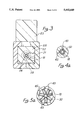
- FIG. 1 is a side elevation view in axial cross-section of a preferred embodiment of the catheter of the present invention with its distal tip operatively disposed in a low profile state in a conduit;
- FIG. 2 is an axial cross-section view similar to FIG. 1 and illustrating the distal tip operatively disposed in an expanded state in the conduit;
- FIG. 3 is a cross-section view taken along lines 3--3 of FIG. 1;
- FIG. 3a is a radial cross-section view taken along lines 3a--3a of FIG. 1;
- FIG. 4 is an enlarged axial cross-section view illustrating the distal tip in its collapsed, low-profile state
- FIG. 4a is a radial cross-section view taken along lines 4a--4a of FIG. 4;
- FIG. 5 is an enlarged axial cross-section view of the distal tip illustrated in its expanded, occlusion state
- FIG. 5a is a radial cross-section view taken along lines 5a-5a of FIG. 5;
- FIG. 6 is a perspective view of the abdominal organs including the liver and gall bladder, and illustrating a preferred method for using the catheter of the present invention.
- FIG. 1 An occlusion catheter is illustrated in FIG. 1 and designated generally by the reference numeral 10.
- the catheter 10 has a longitudinal configuration and extends from a proximal end 12 to a distal end 14.
- the catheter 10 is generally representative of any longitudinal device having near its distal end 14 a section which is expandable from a low profile state to a high profile state.
- the low profile state facilitates insertion of the distal end 14 into a conduit while the high profile state facilitates formation of an occlusive seal with the walls of the conduit.
- This concept is particularly advantageous with respect to surgical devices, such as the catheter 10, wherein the distal end 14 can be inserted through an incision into a body orifice, passage or other conduit 15, and expanded to occlude that conduit.
- the catheter 10 includes an expandable tip section 16 disposed at the distal end 14 of the catheter 10.
- the tip section 16 is defined generally with respect to a longitudinal axis 17, and includes a central element having the configuration of a rod or tube 18.
- the central element has an outer surface 21, and an inner surface 23 which defines a central lumen 25.
- the tube 18 has a rigid configuration and is formed from stainless steel.
- An outer tube 27 is disposed in overlying and circumferential relationship with respect to the inner tube 18.
- the tube 27 has an outer surface 30 and an inner surface 32 which is slidable relative to the outer surface 21 of the tube 18. That is to say, if the central tube 18 is stationary, the outer tube 27 is movable outside the inner tube 18; or, in the alternative, if the outer tube 27 is stationary, the inner tube 18 is movable inside the outer tube 27.
- portions of the outer tube 27 define at least two opposing slots or slits 34, 36 which extend entirely through the outer tube 27 from the outer surface 30 to the inner surface 32.
- These slits 34, 36 are preferably straight and aligned with at least a component in the longitudinal direction.
- the slits 34, 36 can be transverse (but not perpendicular) to the axis 17, or parallel to the axis 17 as in the illustrated embodiment.
- the slits 34, 36 extend from a proximal section 38 of the outer tube 27 to a distal section 41 of the outer tube 27.
- the slits 34, 36 are representative of a plurality of such slits that define at least two fingers 43 which are disposed radially with respect to each other around the outer tube 27 and extend between the proximal section 38 and a distal section 41 of the tube 27.
- there are seven fingers 43 which are individually disposed to extend parallel to the axis 17 and collectively disposed at equal angles of about 51° around the circumference of the outer tube 27.
- the relatively slidable characteristics of the tubes 18, 27 are preserved along the entire catheter 10 except at a location which is distal of the fingers 43.
- the outer tube 27 is fixed to the inner tube 18 at the distal section 41. But proximally of the distal section 41, the tubes 18, 27 are free to slide relative to each other. With this structural configuration, relative movement of the tubes 18, 27 proximally of the distal section 41 results in the radial expansion and collapse of the fingers 43.
- the outer tube 27 functions as a catheter body and the inner rod or tube 18 engages the catheter body distally of the fingers 43 to expand the fingers 43 radially outwardly into circumferential proximity with the body conduit 15.
- the fingers 43 are radially collapsed as illustrated in FIGS. 1 and 4, while in the high profile state the fingers 43 are radially expanded as illustrated in FIGS. 2 and 5.
- the fingers 43 diverge as they expand radially. This divergence tends to create a space (shown generally at 45 in FIG. 5a) between adjacent fingers 43, a space which increases toward the outermost diameter of the expanded fingers 43. While the expanded fingers in this state provide suitable means for anchoring the catheter 10, these spaces 45 prohibit any appreciable degree of occlusion.
- an elastomeric sleeve 50 can be provided for disposition over the fingers 43. As the fingers 43 expand, the elastomeric sleeve 50 also expands providing a continuous surface 52 (best shown in FIG. 5) which faces distally of the catheter 10. In a preferred embodiment, this surface 52 is concave and extends increasingly radially with progressive proximal positions along the axis 17 of the catheter 10.
- the outer surface 30 of the fingers 43 can be bonded or otherwise fixed to the inner surface of the sleeve 50, this is not the case in a preferred embodiment where the fingers 43 are free to slide on the inner surface of the sleeve 50.
- the sleeve 50 need only be sealed to the outer surface 30 at the proximal section 38 and the distal section 41.
- the sleeve 50 can fully enclose the distal end of the catheter 10.
- the sleeve 50 also form a central lumen 54 at the distal end of the catheter 10. This will enable a user to dispense a fluid, such as an injectate, from the catheter 10 through the central lumen 25 of the tube 18, and the central lumen 54 of the sleeve 50 into the conduit 15.
- the sleeve 50 can be disposed to cover the fingers 43 so that expansion of the fingers 43 will carry the sleeve 50 radially outwardly into engagement with the walls of the conduit 15. Then, when the fingers 43 are radially expanded, the sleeve 50 is also expanded and forms the continuous surface 52 which occludes or otherwise blocks the conduit 15. Thus the sleeve 50 provides means for closing the spaces 45 which develop as the fingers 43 diverge in their radial expansion.
- the elastomeric characteristics of the sleeve 50 can be extended beyond the distal end of the tube 18 to form a nose or soft tip 56 at the distal end of the catheter 10.
- This soft tip 56 will reduce any trauma which may result from insertion of the catheter 10 into the conduit 15. In such an embodiment the central lumen 54 would extend through the tip 56.
- various mechanisms can be used to move the distal section 41 relative to the proximal section 38 and thereby expand and collapse the fingers 43.
- This mechanism would also expand and collapse the elastomeric sleeve 50 in an embodiment wherein the sealing function was desired in addition to the anchoring function.
- FIGS. 1 and 2 One such mechanism is illustrated in FIGS. 1 and 2, and includes a housing 61 disposed around an axis 63 which may be different than the axis 17.
- a bend 65 in the catheter 10 so that the axis 63 is disposed at an angle, such as 20°, to the axis 17
- This bend 65 will tend to be fixed in the inner tube 18 which will have a higher degree of rigidity than the outer tube 27 in the embodiment of FIG. 1. Nevertheless, the bend 65 will also occur in the outer tube 27 in spite of the flexibility it will require to slide freely over the tube 18 and around the bend 65 to the proximal section 38.
- Both the inner tube 18 and the outer tube 27 extend into the housing 61.
- the tube 18 projects proximally of the tube 27 and is bonded to a bushing 67 having a radial flange 70 which is received in a radial recess 72 formed by the housing 61.
- the bushing 67 retains the inner tube 18 in an axially fixed relationship with respect to the housing 61.
- An infusion tube 74 can be connected to either the tube 18 or the bushing 67 to accommodate the injection of an infusate, typically through a stopcock 76, into the central lumen 25 of the inner tube 18. In the illustrated embodiment, this infusate flows through the central lumen 25 and through the nose 56 of the sleeve 50 to exit the catheter 10 distally of the occlusive seal formed between the catheter 10 and the conduit 15.
- a subassembly 81 Distally of the bushing 67 in the illustrated embodiment is a subassembly 81 which is fixed to the outer tube 27 but which is movable axially of the housing 61 and therefore the inner tube 18.
- This subassembly 81 includes a thumb tab 83 which is disposed exteriorly of the housing 61, and tube engagement portions 85 which are disposed interiorly of the housing 61.
- the subassembly 81 provides means disposed proximally of the tip section 16 for changing the fingers 43 and sleeve 50 between the low profile state and the high profile state.
- the subassembly 81 is adapted to be slidably mounted to extend through a slot 90 in a wall 92 of the housing 61.
- This wall 92 is configured to extend between opposing flanges 94, 96 of the subassembly 81.
- the wall 92 is provided with transverse recesses or notches shown generally at 98, and the flange 96 is provided with at least one mating tooth 101 to form a ratchet or detent between the subassembly 81 and the housing 61.
- the tube engagement portions 85 it is the purpose of the tube engagement portions 85 to provide a fixed relationship with the outer tube 27 while facilitating a sliding or otherwise movable relationship with the inner tube 18.
- these functions are achieved by a (FIG. 3) distal flange 105 and a proximal flange 107.
- the flange 107 extends transverse to the axis 63 and defines an axial slot 112 which provides a snap fit with the outer tube 27, but a sliding relationship with the inner tube 18.
- the proximal flange 107 also extends transverse of the axis 63 in a generally parallel relationship with the flange 105.
- the flange 107 can also be provided with an axial slot 114 (FIG. 3a) in this case the slot 114 is sized to provide a snap fit with the inner tube 18.
- the flanges 105 and 107 be fixed relative to the outer tube 27. This can be accomplished by gluing or otherwise bonding the outer surface 30 to the flange 107. Another way of accomplishing this objective is to provide a bushing 118 which is bonded to the outer tube 27 between the flanges 105, 107. This bushing 118 provides the outer tube 27 with an increased radius proximally of the flange 105 and distally of the flange 107. If the axial slot 112 in the flange 105 is sized to accommodate only the diameter of the tube 27, then the bushing 118 will inhibit any distal movement of the outer tube 27 relative to the thumb tab 83. Similarly, if the axial slot 114 in the flange 107 is appropriately sized to accommodate only the diameter of the inner tube 18, both the outer tube 27 and the bushing 118 will inhibit any proximal movement of the tube 27 relative to the thumb tab 83.
- the catheter 10 can be adapted for occluding any orifice or body conduit, it is particularly useful in a procedure referred to as cholangiography. This procedure is one of several surgical operations which address the dramatic problems which can result from the formation and migration of gallstones emanating from the gall bladder.
- various body organs including a liver 121, pancreas 123, and duodenum 125, are illustrated relative to a gall bladder 127 which is the organ of origin for gallstones 130.
- a gall bladder 127 which is the organ of origin for gallstones 130.
- One of the purposes associated with the pancreas 123 and the liver 121 is to create acids and other fluids which facilitate the digestion of food in the duodenum 125.
- bile is created between the cells of the liver 121. This bile is collected in the branches of hepatic ducts 132,134, and conducted through a common bile duct 136 into the duodenum 125.
- a sphincter muscle controls the flow of bile and pancreatic juices into the intestine.
- the valve closes causing the bile to back up in the common bile duct 136 and to flow into the gall bladder 127. It is the purpose of the gall bladder 127 to collect and concentrate this bile and to introduce it through a cystic duct 138 back into the common bile duct 136 when it is required for digestion.
- gallstones 130 One of the factors contributing to the formation of gallstones 130 is the general imbalance in this chemical, digestive system. These gallstones 130 tend to migrate into and ultimately occlude the cystic duct 138 and common bile duct 136. This has the dramatic effect of at least partially degrading the important digestive functions associated with the bile.
- the gall bladder 127 is sacrificed in favor of inhibiting the formation of gallstones 130.
- This procedure which ultimately requires removal of the gall bladder 127 has the attendant advantage of also removing any gallstones 130 which reside in the bladder 127. While this part of the procedure addresses the bladder 127 and the stone 130 contained therein, it is of course desirable to consider the possibility that there may be stones which have already migrated into the cystic duct 138 or the common bile duct 136.
- this entire procedure is begun by creating an incision 143 in the cystic duct 138 and introducing a cholangiography catheter, such as the catheter 10, through the incision 143 with the tip section 16 directed toward the common duct 136.
- a cholangiography catheter such as the catheter 10
- the incision 143 can be formed with only a minimal size.
- the thumb tab 83 can be operated to move the proximal section 38 relative to the distal section 40. This will expand the fingers 43 and force the elastomeric sleeve 50 into both anchoring and sealing engagement with the interior surface of the duct 138. This procedure effectively occludes the duct 138 proximally of the nose 56 of the catheter 10.
- An injectate such as radiopaque dye
- Appropriate visualization of this dye will highlight the location of any gallstones 130 in these ducts 132-138, and facilitate their removal in accordance with conventional procedures.
- the cystic duct 138 can be ligated or otherwise occluded, for example by application of a staple distally of the nose 56.
- the fingers 43 and sleeve 150 can then be collapsed to the low profile state and the catheter 10 removed through the incision 143.
- the gall bladder 130 is fully incised and removed from the body.
- both the anchoring and sealing functions associated with the fingers 43 and sleeve 50 are of particular importance to this invention. Both of these functions can be enhanced by reducing the area of contact between the sleeve 50 and the conduit 15.
- the seal has a circular configuration with a radial dimension greater than the normal inner diameter of the body conduit, but a longitudinal dimension less than this radial dimension. This provides a reduced area of contact between the sleeve 50 and the body conduit 15 so that the radial forces exerted by the fingers 43 can create an effective sealing pressure against the body conduit.
- the fingers 43 are expandable to a diameter such as 4 mm. As these fingers 43 contact the conduit 15, they form a circular seal which may have a dimension such as 1 mm measured along the axis 17.
- the subassembly 81 for operating the fingers 43 can be otherwise configured to provide for the relative movement between the inner tube 18 and the outer tube 27.
- the outer tube 27 can be held stationary while the engagement portions 85 of the subassembly 81 extend through in the outer tube 27 to engage the inner tube 18.
- operation of the thumb tab 83 moves the inner tube 18 within the stationary outer tube 27.
- the outer tube 27 would hold the proximal portions 38 stationary while the movable inner tube 18 would move the distal portions 41 to collapse and expand the fingers 43.
- the preferred embodiment requires an inner tube 18 which is relatively flexible.
- This tube 18 can be formed from a co-polyester manufactured by Eastman Plastics and marketed under the trademark KODAR PETG.
- the outer tube 27 can be formed from a rigid material such as stainless steel.
- the elastomeric sleeve 50 in this preferred embodiment is manufactured from a thermal set elastomer such as C-flex® manufactured by Concept Polymers Inc. of Clearwater, Fla.
- the inner tube has an outside diameter of about 0.035 inches and an inside diameter of about 0.023 inches.
- the overlying outer tube 27 has an inside diameter of about 0.037 inches. Its outer diameter extends to about 0.050 inches and provides a snug fit with the sleeve 50 which has an outer diameter of about 0.083 inches.
- catheter 10 has been discussed with reference to preferred embodiments which are particularly useful in a cholangiography procedure, it will be apparent that this occlusion catheter can be otherwise embodied to facilitate insertion into, movement through, anchoring within and occlusion of a body orifice or conduit.
- Various mechanisms for operating the tip section 16 between a collapse and expanded state will also be apparent. All of these variations are deemed to be within the scope of this invention which should be determined not merely by reviewing the discussed and illustrated embodiments, but rather by considering the full extent of the following claims.
Abstract
Description
Claims (29)
Priority Applications (1)
| Application Number | Priority Date | Filing Date | Title |
|---|---|---|---|
| US08/080,972 US5443449A (en) | 1991-03-01 | 1993-06-22 | Cholangiography catheter |
Applications Claiming Priority (2)
| Application Number | Priority Date | Filing Date | Title |
|---|---|---|---|
| US66406791A | 1991-03-01 | 1991-03-01 | |
| US08/080,972 US5443449A (en) | 1991-03-01 | 1993-06-22 | Cholangiography catheter |
Related Parent Applications (1)
| Application Number | Title | Priority Date | Filing Date |
|---|---|---|---|
| US66406791A Continuation | 1991-03-01 | 1991-03-01 |
Publications (1)
| Publication Number | Publication Date |
|---|---|
| US5443449A true US5443449A (en) | 1995-08-22 |
Family
ID=24664385
Family Applications (1)
| Application Number | Title | Priority Date | Filing Date |
|---|---|---|---|
| US08/080,972 Expired - Lifetime US5443449A (en) | 1991-03-01 | 1993-06-22 | Cholangiography catheter |
Country Status (6)
| Country | Link |
|---|---|
| US (1) | US5443449A (en) |
| EP (1) | EP0573591B1 (en) |
| JP (1) | JPH06508769A (en) |
| CA (1) | CA2103592A1 (en) |
| DE (1) | DE69222933T2 (en) |
| WO (1) | WO1992015358A1 (en) |
Cited By (102)
| Publication number | Priority date | Publication date | Assignee | Title |
|---|---|---|---|---|
| US5766203A (en) * | 1995-07-20 | 1998-06-16 | Intelliwire, Inc. | Sheath with expandable distal extremity and balloon catheters and stents for use therewith and method |
| US5954745A (en) * | 1997-05-16 | 1999-09-21 | Gertler; Jonathan | Catheter-filter set having a compliant seal |
| WO1999048550A1 (en) * | 1998-03-27 | 1999-09-30 | Desai Jawahar M | Catheter for media injection |
| US20020077596A1 (en) * | 1997-05-12 | 2002-06-20 | Embol-X, Inc. | Perfusion shunt apparatus and method |
| US6451041B1 (en) | 1996-02-29 | 2002-09-17 | Stephen P. Moenning | Apparatus for protecting a port site opening in the wall of a body cavity and reducing electrosurgical injuries |
| US6461346B1 (en) | 1990-08-29 | 2002-10-08 | Applied Medical Resources Corp. | Sealing occlusion catheter and method of using same |
| US6599299B2 (en) | 2001-06-26 | 2003-07-29 | Leonard S. Schultz | Device and method for body lumen occlusion |
| US20030163114A1 (en) * | 2002-02-26 | 2003-08-28 | Gershowitz Arthur D. | Retrograde cannula having manually retractable sealing member |
| US6620129B2 (en) * | 2001-07-09 | 2003-09-16 | Eric C. Stecker | Enlargeable multifunctional devices |
| US20050004504A1 (en) * | 2003-06-24 | 2005-01-06 | Frye Mark R. | Catheter for extracorporeal treatment |
| US20050119617A1 (en) * | 2001-07-09 | 2005-06-02 | Stecker Eric C. | Multifunctional devices |
| US20050148929A1 (en) * | 2003-11-17 | 2005-07-07 | Bruce Gingles | Catheter with centering wire |
| US20060058598A1 (en) * | 2004-09-14 | 2006-03-16 | Richard Esposito | Catheter having anchoring and stabilizing devices |
| US20060270989A1 (en) * | 2005-05-27 | 2006-11-30 | Mcmichael Donald J | Gastric fastening system |
| US20070078386A1 (en) * | 2005-08-30 | 2007-04-05 | Cytyc Corporation | Movable anchoring catheter |
| US20070161958A1 (en) * | 2006-01-10 | 2007-07-12 | Glenn Bradley J | Stabilized implantable vascular access port |
| US20070179456A1 (en) * | 2006-01-30 | 2007-08-02 | Glenn Bradley J | Bone supported vascular access port |
| US20070232997A1 (en) * | 2006-03-31 | 2007-10-04 | Glenn Bradley J | Subcutaneous catheter retainer |
| US20080097491A1 (en) * | 2006-08-28 | 2008-04-24 | Fred Gobel | Tissue to tissue anchoring device and method of using the same |
| US20080103480A1 (en) * | 2006-10-26 | 2008-05-01 | Cook Critical Care Incorporated | Catheter port configuration |
| US20080121553A1 (en) * | 2006-08-28 | 2008-05-29 | Fred Gobel | Percutaneous gastrointestinal anchoring kit |
| US20080249509A1 (en) * | 2007-04-05 | 2008-10-09 | Glenn Bradley J | Stabilized elongate implantable vascular access device |
| US20090054826A1 (en) * | 2007-08-21 | 2009-02-26 | Cook Critical Care Incorporated | Multi-lumen catheter |
| US20090093765A1 (en) * | 2007-10-09 | 2009-04-09 | Glenn Bradley J | Enhanced stability implantable medical device |
| US20090143713A1 (en) * | 2007-11-30 | 2009-06-04 | Jacques Van Dam | Biliary Shunts, Delivery Systems, Methods of Using the Same and Kits Therefor |
| US20090143637A1 (en) * | 1998-04-24 | 2009-06-04 | Ams Research Corporation | Methods and Apparatus for Correction of Urinary and Gynecological Pathologies, including Treatment of Male Incontinence, and Female Cystocele |
| US7549200B2 (en) | 2005-05-27 | 2009-06-23 | Kimberly-Clark Worldwide, Inc. | Clamp for flexible tube |
| US20090204081A1 (en) * | 2008-02-13 | 2009-08-13 | Depuy Mitek, Inc. | Compression expanded cannula |
| US20100145285A1 (en) * | 2008-12-09 | 2010-06-10 | Cook Critical Care, Incorporated | Multi-lumen catheter configuration |
| US20110024025A1 (en) * | 1998-06-12 | 2011-02-03 | Target Therapeutics, Inc. | Catheter With Knit Section |
| US20110054381A1 (en) * | 2009-05-29 | 2011-03-03 | Jacques Van Dam | Biliary shunts, delivery systems, and methods of using the same |
| US20110137225A1 (en) * | 2009-12-04 | 2011-06-09 | Cook Critical Care Incorporated | Multi-lumen catheter |
| US8002729B2 (en) | 2007-08-21 | 2011-08-23 | Cook Medical Technologies Llc | Multi-lumen catheter assembly |
| US8182528B2 (en) | 2003-12-23 | 2012-05-22 | Sadra Medical, Inc. | Locking heart valve anchor |
| US8231670B2 (en) | 2003-12-23 | 2012-07-31 | Sadra Medical, Inc. | Repositionable heart valve and method |
| US8246678B2 (en) | 2003-12-23 | 2012-08-21 | Sadra Medicl, Inc. | Methods and apparatus for endovascularly replacing a patient's heart valve |
| US8252052B2 (en) | 2003-12-23 | 2012-08-28 | Sadra Medical, Inc. | Methods and apparatus for endovascularly replacing a patient's heart valve |
| US8328868B2 (en) | 2004-11-05 | 2012-12-11 | Sadra Medical, Inc. | Medical devices and delivery systems for delivering medical devices |
| US8343213B2 (en) | 2003-12-23 | 2013-01-01 | Sadra Medical, Inc. | Leaflet engagement elements and methods for use thereof |
| US8579962B2 (en) | 2003-12-23 | 2013-11-12 | Sadra Medical, Inc. | Methods and apparatus for performing valvuloplasty |
| ES2432845A1 (en) * | 2012-06-05 | 2013-12-05 | Universidad De Málaga | Intraoperative cholangiography cannula (Machine-translation by Google Translate, not legally binding) |
| US8603160B2 (en) | 2003-12-23 | 2013-12-10 | Sadra Medical, Inc. | Method of using a retrievable heart valve anchor with a sheath |
| US8623076B2 (en) | 2003-12-23 | 2014-01-07 | Sadra Medical, Inc. | Low profile heart valve and delivery system |
| US8668733B2 (en) | 2004-06-16 | 2014-03-11 | Sadra Medical, Inc. | Everting heart valve |
| US8828078B2 (en) | 2003-12-23 | 2014-09-09 | Sadra Medical, Inc. | Methods and apparatus for endovascular heart valve replacement comprising tissue grasping elements |
| US8840663B2 (en) | 2003-12-23 | 2014-09-23 | Sadra Medical, Inc. | Repositionable heart valve method |
| US8858620B2 (en) | 2003-12-23 | 2014-10-14 | Sadra Medical Inc. | Methods and apparatus for endovascularly replacing a heart valve |
| US8894703B2 (en) | 2003-12-23 | 2014-11-25 | Sadra Medical, Inc. | Systems and methods for delivering a medical implant |
| US8998976B2 (en) | 2011-07-12 | 2015-04-07 | Boston Scientific Scimed, Inc. | Coupling system for medical devices |
| US9005273B2 (en) | 2003-12-23 | 2015-04-14 | Sadra Medical, Inc. | Assessing the location and performance of replacement heart valves |
| US9011521B2 (en) | 2003-12-23 | 2015-04-21 | Sadra Medical, Inc. | Methods and apparatus for endovascularly replacing a patient's heart valve |
| US20150306350A1 (en) * | 2013-01-18 | 2015-10-29 | Sri International | Anchoring Nerve Block Catheter |
| US9248253B2 (en) | 2007-08-21 | 2016-02-02 | Cook Medical Technologies Llc | Winged catheter assembly |
| US9370421B2 (en) | 2011-12-03 | 2016-06-21 | Boston Scientific Scimed, Inc. | Medical device handle |
| US9415225B2 (en) | 2005-04-25 | 2016-08-16 | Cardiac Pacemakers, Inc. | Method and apparatus for pacing during revascularization |
| US9526609B2 (en) | 2003-12-23 | 2016-12-27 | Boston Scientific Scimed, Inc. | Methods and apparatus for endovascularly replacing a patient's heart valve |
| US9788942B2 (en) | 2015-02-03 | 2017-10-17 | Boston Scientific Scimed Inc. | Prosthetic heart valve having tubular seal |
| US20170325938A1 (en) | 2016-05-16 | 2017-11-16 | Boston Scientific Scimed, Inc. | Replacement heart valve implant with invertible leaflets |
| US9861477B2 (en) | 2015-01-26 | 2018-01-09 | Boston Scientific Scimed Inc. | Prosthetic heart valve square leaflet-leaflet stitch |
| US9901445B2 (en) | 2014-11-21 | 2018-02-27 | Boston Scientific Scimed, Inc. | Valve locking mechanism |
| US10080652B2 (en) | 2015-03-13 | 2018-09-25 | Boston Scientific Scimed, Inc. | Prosthetic heart valve having an improved tubular seal |
| US10136991B2 (en) | 2015-08-12 | 2018-11-27 | Boston Scientific Scimed Inc. | Replacement heart valve implant |
| US10172708B2 (en) | 2012-01-25 | 2019-01-08 | Boston Scientific Scimed, Inc. | Valve assembly with a bioabsorbable gasket and a replaceable valve implant |
| US10179041B2 (en) | 2015-08-12 | 2019-01-15 | Boston Scientific Scimed Icn. | Pinless release mechanism |
| US10195392B2 (en) | 2015-07-02 | 2019-02-05 | Boston Scientific Scimed, Inc. | Clip-on catheter |
| US10201418B2 (en) | 2010-09-10 | 2019-02-12 | Symetis, SA | Valve replacement devices, delivery device for a valve replacement device and method of production of a valve replacement device |
| US10201417B2 (en) | 2015-02-03 | 2019-02-12 | Boston Scientific Scimed Inc. | Prosthetic heart valve having tubular seal |
| US10258465B2 (en) | 2003-12-23 | 2019-04-16 | Boston Scientific Scimed Inc. | Methods and apparatus for endovascular heart valve replacement comprising tissue grasping elements |
| US10278805B2 (en) | 2000-08-18 | 2019-05-07 | Atritech, Inc. | Expandable implant devices for filtering blood flow from atrial appendages |
| US10285809B2 (en) | 2015-03-06 | 2019-05-14 | Boston Scientific Scimed Inc. | TAVI anchoring assist device |
| US10299922B2 (en) | 2005-12-22 | 2019-05-28 | Symetis Sa | Stent-valves for valve replacement and associated methods and systems for surgery |
| US10335277B2 (en) | 2015-07-02 | 2019-07-02 | Boston Scientific Scimed Inc. | Adjustable nosecone |
| US10342660B2 (en) | 2016-02-02 | 2019-07-09 | Boston Scientific Inc. | Tensioned sheathing aids |
| US10426617B2 (en) | 2015-03-06 | 2019-10-01 | Boston Scientific Scimed, Inc. | Low profile valve locking mechanism and commissure assembly |
| US10449043B2 (en) | 2015-01-16 | 2019-10-22 | Boston Scientific Scimed, Inc. | Displacement based lock and release mechanism |
| US10555809B2 (en) | 2012-06-19 | 2020-02-11 | Boston Scientific Scimed, Inc. | Replacement heart valve |
| US10583005B2 (en) | 2016-05-13 | 2020-03-10 | Boston Scientific Scimed, Inc. | Medical device handle |
| US10828154B2 (en) | 2017-06-08 | 2020-11-10 | Boston Scientific Scimed, Inc. | Heart valve implant commissure support structure |
| US10898325B2 (en) | 2017-08-01 | 2021-01-26 | Boston Scientific Scimed, Inc. | Medical implant locking mechanism |
| US10939996B2 (en) | 2017-08-16 | 2021-03-09 | Boston Scientific Scimed, Inc. | Replacement heart valve commissure assembly |
| US10993805B2 (en) | 2008-02-26 | 2021-05-04 | Jenavalve Technology, Inc. | Stent for the positioning and anchoring of a valvular prosthesis in an implantation site in the heart of a patient |
| US11065138B2 (en) | 2016-05-13 | 2021-07-20 | Jenavalve Technology, Inc. | Heart valve prosthesis delivery system and method for delivery of heart valve prosthesis with introducer sheath and loading system |
| US11147668B2 (en) | 2018-02-07 | 2021-10-19 | Boston Scientific Scimed, Inc. | Medical device delivery system with alignment feature |
| US11185405B2 (en) | 2013-08-30 | 2021-11-30 | Jenavalve Technology, Inc. | Radially collapsible frame for a prosthetic valve and method for manufacturing such a frame |
| US11191641B2 (en) | 2018-01-19 | 2021-12-07 | Boston Scientific Scimed, Inc. | Inductance mode deployment sensors for transcatheter valve system |
| US11197754B2 (en) | 2017-01-27 | 2021-12-14 | Jenavalve Technology, Inc. | Heart valve mimicry |
| US11229517B2 (en) | 2018-05-15 | 2022-01-25 | Boston Scientific Scimed, Inc. | Replacement heart valve commissure assembly |
| US11241312B2 (en) | 2018-12-10 | 2022-02-08 | Boston Scientific Scimed, Inc. | Medical device delivery system including a resistance member |
| US11241310B2 (en) | 2018-06-13 | 2022-02-08 | Boston Scientific Scimed, Inc. | Replacement heart valve delivery device |
| US11246625B2 (en) | 2018-01-19 | 2022-02-15 | Boston Scientific Scimed, Inc. | Medical device delivery system with feedback loop |
| US11278398B2 (en) | 2003-12-23 | 2022-03-22 | Boston Scientific Scimed, Inc. | Methods and apparatus for endovascular heart valve replacement comprising tissue grasping elements |
| US11285002B2 (en) | 2003-12-23 | 2022-03-29 | Boston Scientific Scimed, Inc. | Methods and apparatus for endovascularly replacing a heart valve |
| US11337800B2 (en) | 2015-05-01 | 2022-05-24 | Jenavalve Technology, Inc. | Device and method with reduced pacemaker rate in heart valve replacement |
| WO2022119906A1 (en) * | 2020-12-01 | 2022-06-09 | Becton, Dickinson And Company | Catheter delivery device to facilitate blood draw |
| US11357624B2 (en) | 2007-04-13 | 2022-06-14 | Jenavalve Technology, Inc. | Medical device for treating a heart valve insufficiency |
| US11439732B2 (en) | 2018-02-26 | 2022-09-13 | Boston Scientific Scimed, Inc. | Embedded radiopaque marker in adaptive seal |
| US11439504B2 (en) | 2019-05-10 | 2022-09-13 | Boston Scientific Scimed, Inc. | Replacement heart valve with improved cusp washout and reduced loading |
| US11517431B2 (en) | 2005-01-20 | 2022-12-06 | Jenavalve Technology, Inc. | Catheter system for implantation of prosthetic heart valves |
| US11564794B2 (en) | 2008-02-26 | 2023-01-31 | Jenavalve Technology, Inc. | Stent for the positioning and anchoring of a valvular prosthesis in an implantation site in the heart of a patient |
| US11589981B2 (en) | 2010-05-25 | 2023-02-28 | Jenavalve Technology, Inc. | Prosthetic heart valve and transcatheter delivered endoprosthesis comprising a prosthetic heart valve and a stent |
| US11771544B2 (en) | 2011-05-05 | 2023-10-03 | Symetis Sa | Method and apparatus for compressing/loading stent-valves |
| US11877751B2 (en) | 2019-08-29 | 2024-01-23 | Emory University | Methods and devices configured to prevent aspiration |
Families Citing this family (2)
| Publication number | Priority date | Publication date | Assignee | Title |
|---|---|---|---|---|
| US5456667A (en) * | 1993-05-20 | 1995-10-10 | Advanced Cardiovascular Systems, Inc. | Temporary stenting catheter with one-piece expandable segment |
| WO1996020750A1 (en) * | 1995-01-04 | 1996-07-11 | Medtronic, Inc. | Improved method of soft tip forming |
Citations (16)
| Publication number | Priority date | Publication date | Assignee | Title |
|---|---|---|---|---|
| US3397699A (en) * | 1966-05-05 | 1968-08-20 | Gerald C. Kohl | Retaining catheter having resiliently biased wing flanges |
| US3568659A (en) * | 1968-09-24 | 1971-03-09 | James N Karnegis | Disposable percutaneous intracardiac pump and method of pumping blood |
| US4043338A (en) * | 1973-04-30 | 1977-08-23 | Ortho Pharmaceutical Corporation | Pharmaceutical formulation applicator device |
| US4263917A (en) * | 1979-04-06 | 1981-04-28 | Moss James P | Method of sealing bile duct during cholangiography |
| US4516578A (en) * | 1982-09-30 | 1985-05-14 | Luther Shuffield | Rectal device and method of inserting same |
| US4572186A (en) * | 1983-12-07 | 1986-02-25 | Cordis Corporation | Vessel dilation |
| US4699611A (en) * | 1985-04-19 | 1987-10-13 | C. R. Bard, Inc. | Biliary stent introducer |
| US4723549A (en) * | 1986-09-18 | 1988-02-09 | Wholey Mark H | Method and apparatus for dilating blood vessels |
| US4779611A (en) * | 1987-02-24 | 1988-10-25 | Grooters Ronald K | Disposable surgical scope guide |
| US4861337A (en) * | 1988-03-02 | 1989-08-29 | Sherwood Medical Company | Collapsible urethral catheter |
| DE3818279A1 (en) * | 1988-05-30 | 1989-12-14 | Friedhelm Dr Brassel | Auxiliary device and method of fastening detachable balloons on the tip of microcatheters |
| US4919651A (en) * | 1988-04-15 | 1990-04-24 | Santa Barbara Medical Foundation Clinic | Catheter having a double lumen and a balloon and method of using the same for controlled operative cholangiography |
| US5049131A (en) * | 1989-05-31 | 1991-09-17 | Ashridge Ag | Balloon catheter |
| US5053009A (en) * | 1989-04-07 | 1991-10-01 | Renate Dunsch-Herzberg | Drainage and instrument duct for the arthroscopy |
| US5071429A (en) * | 1990-08-24 | 1991-12-10 | Medical Engineering Corporation | Method for inserting a balloon catheter through an endoscope |
| US5073166A (en) * | 1989-02-15 | 1991-12-17 | Medical Innovations Corporation | Method and apparatus for emplacement of a gastrostomy catheter |
-
1992
- 1992-02-25 EP EP92908105A patent/EP0573591B1/en not_active Expired - Lifetime
- 1992-02-25 CA CA002103592A patent/CA2103592A1/en not_active Abandoned
- 1992-02-25 WO PCT/US1992/001460 patent/WO1992015358A1/en active IP Right Grant
- 1992-02-25 JP JP4508195A patent/JPH06508769A/en active Pending
- 1992-02-25 DE DE69222933T patent/DE69222933T2/en not_active Expired - Lifetime
-
1993
- 1993-06-22 US US08/080,972 patent/US5443449A/en not_active Expired - Lifetime
Patent Citations (16)
| Publication number | Priority date | Publication date | Assignee | Title |
|---|---|---|---|---|
| US3397699A (en) * | 1966-05-05 | 1968-08-20 | Gerald C. Kohl | Retaining catheter having resiliently biased wing flanges |
| US3568659A (en) * | 1968-09-24 | 1971-03-09 | James N Karnegis | Disposable percutaneous intracardiac pump and method of pumping blood |
| US4043338A (en) * | 1973-04-30 | 1977-08-23 | Ortho Pharmaceutical Corporation | Pharmaceutical formulation applicator device |
| US4263917A (en) * | 1979-04-06 | 1981-04-28 | Moss James P | Method of sealing bile duct during cholangiography |
| US4516578A (en) * | 1982-09-30 | 1985-05-14 | Luther Shuffield | Rectal device and method of inserting same |
| US4572186A (en) * | 1983-12-07 | 1986-02-25 | Cordis Corporation | Vessel dilation |
| US4699611A (en) * | 1985-04-19 | 1987-10-13 | C. R. Bard, Inc. | Biliary stent introducer |
| US4723549A (en) * | 1986-09-18 | 1988-02-09 | Wholey Mark H | Method and apparatus for dilating blood vessels |
| US4779611A (en) * | 1987-02-24 | 1988-10-25 | Grooters Ronald K | Disposable surgical scope guide |
| US4861337A (en) * | 1988-03-02 | 1989-08-29 | Sherwood Medical Company | Collapsible urethral catheter |
| US4919651A (en) * | 1988-04-15 | 1990-04-24 | Santa Barbara Medical Foundation Clinic | Catheter having a double lumen and a balloon and method of using the same for controlled operative cholangiography |
| DE3818279A1 (en) * | 1988-05-30 | 1989-12-14 | Friedhelm Dr Brassel | Auxiliary device and method of fastening detachable balloons on the tip of microcatheters |
| US5073166A (en) * | 1989-02-15 | 1991-12-17 | Medical Innovations Corporation | Method and apparatus for emplacement of a gastrostomy catheter |
| US5053009A (en) * | 1989-04-07 | 1991-10-01 | Renate Dunsch-Herzberg | Drainage and instrument duct for the arthroscopy |
| US5049131A (en) * | 1989-05-31 | 1991-09-17 | Ashridge Ag | Balloon catheter |
| US5071429A (en) * | 1990-08-24 | 1991-12-10 | Medical Engineering Corporation | Method for inserting a balloon catheter through an endoscope |
Cited By (178)
| Publication number | Priority date | Publication date | Assignee | Title |
|---|---|---|---|---|
| US6461346B1 (en) | 1990-08-29 | 2002-10-08 | Applied Medical Resources Corp. | Sealing occlusion catheter and method of using same |
| US6052612A (en) * | 1995-06-07 | 2000-04-18 | Desai; Jawahar M. | Catheter for media injection |
| US6701180B1 (en) | 1995-06-07 | 2004-03-02 | Jawahar M. Desai | Catheter for media injection |
| US20090048511A1 (en) * | 1995-06-07 | 2009-02-19 | Desai Jawahar M | Catheter For Media Injection |
| US5766203A (en) * | 1995-07-20 | 1998-06-16 | Intelliwire, Inc. | Sheath with expandable distal extremity and balloon catheters and stents for use therewith and method |
| US6451041B1 (en) | 1996-02-29 | 2002-09-17 | Stephen P. Moenning | Apparatus for protecting a port site opening in the wall of a body cavity and reducing electrosurgical injuries |
| US20020193806A1 (en) * | 1996-02-29 | 2002-12-19 | Stephen P. Moenning | Apparatus and procedure for protecting a port site opening in the wall of a body cavity and reducing electrosurgical injuries |
| US20020077596A1 (en) * | 1997-05-12 | 2002-06-20 | Embol-X, Inc. | Perfusion shunt apparatus and method |
| US5954745A (en) * | 1997-05-16 | 1999-09-21 | Gertler; Jonathan | Catheter-filter set having a compliant seal |
| WO1999048550A1 (en) * | 1998-03-27 | 1999-09-30 | Desai Jawahar M | Catheter for media injection |
| US20090143637A1 (en) * | 1998-04-24 | 2009-06-04 | Ams Research Corporation | Methods and Apparatus for Correction of Urinary and Gynecological Pathologies, including Treatment of Male Incontinence, and Female Cystocele |
| US8162814B2 (en) * | 1998-04-24 | 2012-04-24 | Ams Research Corporation | Methods and apparatus for correction of urinary and gynecological pathologies, including treatment of male incontinence, and female cystocele |
| US20110024025A1 (en) * | 1998-06-12 | 2011-02-03 | Target Therapeutics, Inc. | Catheter With Knit Section |
| US8181324B2 (en) | 1998-06-12 | 2012-05-22 | Target Therapeutics, Inc. | Catheter with knit section |
| US10278805B2 (en) | 2000-08-18 | 2019-05-07 | Atritech, Inc. | Expandable implant devices for filtering blood flow from atrial appendages |
| US20040073317A1 (en) * | 2001-06-26 | 2004-04-15 | Schultz Leonard S. | Device and method for body lumen occlusion |
| US6599299B2 (en) | 2001-06-26 | 2003-07-29 | Leonard S. Schultz | Device and method for body lumen occlusion |
| US20050119617A1 (en) * | 2001-07-09 | 2005-06-02 | Stecker Eric C. | Multifunctional devices |
| US20040097877A1 (en) * | 2001-07-09 | 2004-05-20 | Stecker Eric C. | Enlargeable multifunctional devices |
| US6620129B2 (en) * | 2001-07-09 | 2003-09-16 | Eric C. Stecker | Enlargeable multifunctional devices |
| US6918888B2 (en) * | 2002-02-26 | 2005-07-19 | Terumo Cardiovascular Systems | Retrograde cannula having manually retractable sealing member |
| US20040199111A1 (en) * | 2002-02-26 | 2004-10-07 | Terumo Cardiovascular Systems Corporation | Retrograde cannula having manually retractable sealing member |
| US20030163114A1 (en) * | 2002-02-26 | 2003-08-28 | Gershowitz Arthur D. | Retrograde cannula having manually retractable sealing member |
| US20050004504A1 (en) * | 2003-06-24 | 2005-01-06 | Frye Mark R. | Catheter for extracorporeal treatment |
| US20050148929A1 (en) * | 2003-11-17 | 2005-07-07 | Bruce Gingles | Catheter with centering wire |
| US7922687B2 (en) | 2003-11-17 | 2011-04-12 | Cook Medical Technologies Llc | Catheter with centering wire |
| US10426608B2 (en) | 2003-12-23 | 2019-10-01 | Boston Scientific Scimed, Inc. | Repositionable heart valve |
| US9585750B2 (en) | 2003-12-23 | 2017-03-07 | Boston Scientific Scimed, Inc. | Methods and apparatus for endovascularly replacing a patient's heart valve |
| US11696825B2 (en) | 2003-12-23 | 2023-07-11 | Boston Scientific Scimed, Inc. | Replacement valve and anchor |
| US9308085B2 (en) | 2003-12-23 | 2016-04-12 | Boston Scientific Scimed, Inc. | Repositionable heart valve and method |
| US9320599B2 (en) | 2003-12-23 | 2016-04-26 | Boston Scientific Scimed, Inc. | Methods and apparatus for endovascularly replacing a heart valve |
| US11285002B2 (en) | 2003-12-23 | 2022-03-29 | Boston Scientific Scimed, Inc. | Methods and apparatus for endovascularly replacing a heart valve |
| US11278398B2 (en) | 2003-12-23 | 2022-03-22 | Boston Scientific Scimed, Inc. | Methods and apparatus for endovascular heart valve replacement comprising tissue grasping elements |
| US11185408B2 (en) | 2003-12-23 | 2021-11-30 | Boston Scientific Scimed, Inc. | Methods and apparatus for endovascular heart valve replacement comprising tissue grasping elements |
| US10925724B2 (en) | 2003-12-23 | 2021-02-23 | Boston Scientific Scimed, Inc. | Replacement valve and anchor |
| US10716663B2 (en) | 2003-12-23 | 2020-07-21 | Boston Scientific Scimed, Inc. | Methods and apparatus for performing valvuloplasty |
| US9011521B2 (en) | 2003-12-23 | 2015-04-21 | Sadra Medical, Inc. | Methods and apparatus for endovascularly replacing a patient's heart valve |
| US10478289B2 (en) | 2003-12-23 | 2019-11-19 | Boston Scientific Scimed, Inc. | Replacement valve and anchor |
| US9005273B2 (en) | 2003-12-23 | 2015-04-14 | Sadra Medical, Inc. | Assessing the location and performance of replacement heart valves |
| US10413409B2 (en) | 2003-12-23 | 2019-09-17 | Boston Scientific Scimed, Inc. | Systems and methods for delivering a medical implant |
| US10413412B2 (en) | 2003-12-23 | 2019-09-17 | Boston Scientific Scimed, Inc. | Methods and apparatus for endovascularly replacing a heart valve |
| US9358110B2 (en) | 2003-12-23 | 2016-06-07 | Boston Scientific Scimed, Inc. | Medical devices and delivery systems for delivering medical devices |
| US10357359B2 (en) | 2003-12-23 | 2019-07-23 | Boston Scientific Scimed Inc | Methods and apparatus for endovascularly replacing a patient's heart valve |
| US10335273B2 (en) | 2003-12-23 | 2019-07-02 | Boston Scientific Scimed Inc. | Leaflet engagement elements and methods for use thereof |
| US10314695B2 (en) | 2003-12-23 | 2019-06-11 | Boston Scientific Scimed Inc. | Methods and apparatus for endovascular heart valve replacement comprising tissue grasping elements |
| US10258465B2 (en) | 2003-12-23 | 2019-04-16 | Boston Scientific Scimed Inc. | Methods and apparatus for endovascular heart valve replacement comprising tissue grasping elements |
| US10206774B2 (en) | 2003-12-23 | 2019-02-19 | Boston Scientific Scimed Inc. | Low profile heart valve and delivery system |
| US9956075B2 (en) | 2003-12-23 | 2018-05-01 | Boston Scientific Scimed Inc. | Methods and apparatus for endovascularly replacing a heart valve |
| US9872768B2 (en) | 2003-12-23 | 2018-01-23 | Boston Scientific Scimed, Inc. | Medical devices and delivery systems for delivering medical devices |
| US9861476B2 (en) | 2003-12-23 | 2018-01-09 | Boston Scientific Scimed Inc. | Leaflet engagement elements and methods for use thereof |
| US8894703B2 (en) | 2003-12-23 | 2014-11-25 | Sadra Medical, Inc. | Systems and methods for delivering a medical implant |
| US8182528B2 (en) | 2003-12-23 | 2012-05-22 | Sadra Medical, Inc. | Locking heart valve anchor |
| US9585749B2 (en) | 2003-12-23 | 2017-03-07 | Boston Scientific Scimed, Inc. | Replacement heart valve assembly |
| US9277991B2 (en) | 2003-12-23 | 2016-03-08 | Boston Scientific Scimed, Inc. | Low profile heart valve and delivery system |
| US8231670B2 (en) | 2003-12-23 | 2012-07-31 | Sadra Medical, Inc. | Repositionable heart valve and method |
| US8246678B2 (en) | 2003-12-23 | 2012-08-21 | Sadra Medicl, Inc. | Methods and apparatus for endovascularly replacing a patient's heart valve |
| US8252052B2 (en) | 2003-12-23 | 2012-08-28 | Sadra Medical, Inc. | Methods and apparatus for endovascularly replacing a patient's heart valve |
| US9532872B2 (en) | 2003-12-23 | 2017-01-03 | Boston Scientific Scimed, Inc. | Systems and methods for delivering a medical implant |
| US8858620B2 (en) | 2003-12-23 | 2014-10-14 | Sadra Medical Inc. | Methods and apparatus for endovascularly replacing a heart valve |
| US8343213B2 (en) | 2003-12-23 | 2013-01-01 | Sadra Medical, Inc. | Leaflet engagement elements and methods for use thereof |
| US9526609B2 (en) | 2003-12-23 | 2016-12-27 | Boston Scientific Scimed, Inc. | Methods and apparatus for endovascularly replacing a patient's heart valve |
| US9393113B2 (en) | 2003-12-23 | 2016-07-19 | Boston Scientific Scimed Inc. | Retrievable heart valve anchor and method |
| US8579962B2 (en) | 2003-12-23 | 2013-11-12 | Sadra Medical, Inc. | Methods and apparatus for performing valvuloplasty |
| US9358106B2 (en) | 2003-12-23 | 2016-06-07 | Boston Scientific Scimed Inc. | Methods and apparatus for performing valvuloplasty |
| US8603160B2 (en) | 2003-12-23 | 2013-12-10 | Sadra Medical, Inc. | Method of using a retrievable heart valve anchor with a sheath |
| US8840663B2 (en) | 2003-12-23 | 2014-09-23 | Sadra Medical, Inc. | Repositionable heart valve method |
| US8623076B2 (en) | 2003-12-23 | 2014-01-07 | Sadra Medical, Inc. | Low profile heart valve and delivery system |
| US8623078B2 (en) | 2003-12-23 | 2014-01-07 | Sadra Medical, Inc. | Replacement valve and anchor |
| US8840662B2 (en) | 2003-12-23 | 2014-09-23 | Sadra Medical, Inc. | Repositionable heart valve and method |
| US8828078B2 (en) | 2003-12-23 | 2014-09-09 | Sadra Medical, Inc. | Methods and apparatus for endovascular heart valve replacement comprising tissue grasping elements |
| US8668733B2 (en) | 2004-06-16 | 2014-03-11 | Sadra Medical, Inc. | Everting heart valve |
| US9744035B2 (en) | 2004-06-16 | 2017-08-29 | Boston Scientific Scimed, Inc. | Everting heart valve |
| US8992608B2 (en) | 2004-06-16 | 2015-03-31 | Sadra Medical, Inc. | Everting heart valve |
| US11484405B2 (en) | 2004-06-16 | 2022-11-01 | Boston Scientific Scimed, Inc. | Everting heart valve |
| US7753906B2 (en) | 2004-09-14 | 2010-07-13 | Richard Esposito | Catheter having anchoring and stabilizing devices |
| US20060058598A1 (en) * | 2004-09-14 | 2006-03-16 | Richard Esposito | Catheter having anchoring and stabilizing devices |
| US8617236B2 (en) | 2004-11-05 | 2013-12-31 | Sadra Medical, Inc. | Medical devices and delivery systems for delivering medical devices |
| US8328868B2 (en) | 2004-11-05 | 2012-12-11 | Sadra Medical, Inc. | Medical devices and delivery systems for delivering medical devices |
| US10531952B2 (en) | 2004-11-05 | 2020-01-14 | Boston Scientific Scimed, Inc. | Medical devices and delivery systems for delivering medical devices |
| US11517431B2 (en) | 2005-01-20 | 2022-12-06 | Jenavalve Technology, Inc. | Catheter system for implantation of prosthetic heart valves |
| US9649495B2 (en) | 2005-04-25 | 2017-05-16 | Cardiac Pacemakers, Inc. | Method and apparatus for pacing during revascularization |
| US9415225B2 (en) | 2005-04-25 | 2016-08-16 | Cardiac Pacemakers, Inc. | Method and apparatus for pacing during revascularization |
| US10549101B2 (en) | 2005-04-25 | 2020-02-04 | Cardiac Pacemakers, Inc. | Method and apparatus for pacing during revascularization |
| US20060270989A1 (en) * | 2005-05-27 | 2006-11-30 | Mcmichael Donald J | Gastric fastening system |
| US7549200B2 (en) | 2005-05-27 | 2009-06-23 | Kimberly-Clark Worldwide, Inc. | Clamp for flexible tube |
| US20070078386A1 (en) * | 2005-08-30 | 2007-04-05 | Cytyc Corporation | Movable anchoring catheter |
| US10299922B2 (en) | 2005-12-22 | 2019-05-28 | Symetis Sa | Stent-valves for valve replacement and associated methods and systems for surgery |
| US10314701B2 (en) | 2005-12-22 | 2019-06-11 | Symetis Sa | Stent-valves for valve replacement and associated methods and systems for surgery |
| US8282610B1 (en) | 2006-01-10 | 2012-10-09 | Stealth Therapeutics, Inc. | Stabilized implantable vascular access port |
| US7708722B2 (en) | 2006-01-10 | 2010-05-04 | Stealth Therapeutics, Inc. | Stabilized implantable vascular access port |
| US20070161958A1 (en) * | 2006-01-10 | 2007-07-12 | Glenn Bradley J | Stabilized implantable vascular access port |
| US7608065B2 (en) | 2006-01-30 | 2009-10-27 | Glenn Bradley J | Bone supported vascular access port |
| US20070179456A1 (en) * | 2006-01-30 | 2007-08-02 | Glenn Bradley J | Bone supported vascular access port |
| US9138563B2 (en) * | 2006-03-31 | 2015-09-22 | Stealth Therapeutics, Inc. | Subcutaneous catheter retainer |
| US20070232997A1 (en) * | 2006-03-31 | 2007-10-04 | Glenn Bradley J | Subcutaneous catheter retainer |
| US7582098B2 (en) | 2006-08-28 | 2009-09-01 | Kimberly-Clark Wolrdwide, Inc. | Percutaneous gastrointestinal anchoring kit |
| US20080121553A1 (en) * | 2006-08-28 | 2008-05-29 | Fred Gobel | Percutaneous gastrointestinal anchoring kit |
| US20080097491A1 (en) * | 2006-08-28 | 2008-04-24 | Fred Gobel | Tissue to tissue anchoring device and method of using the same |
| US20080103480A1 (en) * | 2006-10-26 | 2008-05-01 | Cook Critical Care Incorporated | Catheter port configuration |
| US8545434B2 (en) | 2006-10-26 | 2013-10-01 | Cook Medical Technology LLC | Catheter port configuration |
| US8083723B2 (en) | 2007-04-05 | 2011-12-27 | Stealth Therapeutics, Inc. | Stabilized elongate implantable vascular access device |
| US20080249509A1 (en) * | 2007-04-05 | 2008-10-09 | Glenn Bradley J | Stabilized elongate implantable vascular access device |
| US11357624B2 (en) | 2007-04-13 | 2022-06-14 | Jenavalve Technology, Inc. | Medical device for treating a heart valve insufficiency |
| US20090054826A1 (en) * | 2007-08-21 | 2009-02-26 | Cook Critical Care Incorporated | Multi-lumen catheter |
| US8002729B2 (en) | 2007-08-21 | 2011-08-23 | Cook Medical Technologies Llc | Multi-lumen catheter assembly |
| US9248253B2 (en) | 2007-08-21 | 2016-02-02 | Cook Medical Technologies Llc | Winged catheter assembly |
| US7753868B2 (en) | 2007-08-21 | 2010-07-13 | Cook Critical Care Incorporated | Multi-lumen catheter |
| US20090093765A1 (en) * | 2007-10-09 | 2009-04-09 | Glenn Bradley J | Enhanced stability implantable medical device |
| US8209015B2 (en) | 2007-10-09 | 2012-06-26 | Stealth Therapeutics, Inc. | Enhanced stability implantable medical device |
| US20090143759A1 (en) * | 2007-11-30 | 2009-06-04 | Jacques Van Dam | Methods, Devices, Kits and Systems for Defunctionalizing the Cystic Duct |
| US20110071350A1 (en) * | 2007-11-30 | 2011-03-24 | Jacques Van Dam | Applicator for endoscopic treatment of biliary disease |
| US9486219B2 (en) | 2007-11-30 | 2016-11-08 | Treus Medical, Inc. | Biliary shunts, delivery systems, methods of using the same and kits therefor |
| US20090143713A1 (en) * | 2007-11-30 | 2009-06-04 | Jacques Van Dam | Biliary Shunts, Delivery Systems, Methods of Using the Same and Kits Therefor |
| US9282968B2 (en) | 2007-11-30 | 2016-03-15 | Treus Medical, Inc. | Applicator for endoscopic treatment of biliary disease |
| US20090204081A1 (en) * | 2008-02-13 | 2009-08-13 | Depuy Mitek, Inc. | Compression expanded cannula |
| US9161747B2 (en) | 2008-02-13 | 2015-10-20 | Depuy Mitek, Llc | Compression expanded cannula |
| US11154398B2 (en) | 2008-02-26 | 2021-10-26 | JenaValve Technology. Inc. | Stent for the positioning and anchoring of a valvular prosthesis in an implantation site in the heart of a patient |
| US11564794B2 (en) | 2008-02-26 | 2023-01-31 | Jenavalve Technology, Inc. | Stent for the positioning and anchoring of a valvular prosthesis in an implantation site in the heart of a patient |
| US10993805B2 (en) | 2008-02-26 | 2021-05-04 | Jenavalve Technology, Inc. | Stent for the positioning and anchoring of a valvular prosthesis in an implantation site in the heart of a patient |
| US20100145285A1 (en) * | 2008-12-09 | 2010-06-10 | Cook Critical Care, Incorporated | Multi-lumen catheter configuration |
| US9901347B2 (en) | 2009-05-29 | 2018-02-27 | Terus Medical, Inc. | Biliary shunts, delivery systems, and methods of using the same |
| US20110054381A1 (en) * | 2009-05-29 | 2011-03-03 | Jacques Van Dam | Biliary shunts, delivery systems, and methods of using the same |
| US20110137225A1 (en) * | 2009-12-04 | 2011-06-09 | Cook Critical Care Incorporated | Multi-lumen catheter |
| US8496607B2 (en) | 2009-12-04 | 2013-07-30 | Cook Medical Technologies Llc | Multi-lumen catheter |
| US9192710B2 (en) | 2009-12-04 | 2015-11-24 | Cook Medical Technologies Llc | Multi-lumen catheter |
| US11589981B2 (en) | 2010-05-25 | 2023-02-28 | Jenavalve Technology, Inc. | Prosthetic heart valve and transcatheter delivered endoprosthesis comprising a prosthetic heart valve and a stent |
| US10869760B2 (en) | 2010-09-10 | 2020-12-22 | Symetis Sa | Valve replacement devices, delivery device for a valve replacement device and method of production of a valve replacement device |
| US10201418B2 (en) | 2010-09-10 | 2019-02-12 | Symetis, SA | Valve replacement devices, delivery device for a valve replacement device and method of production of a valve replacement device |
| US11771544B2 (en) | 2011-05-05 | 2023-10-03 | Symetis Sa | Method and apparatus for compressing/loading stent-valves |
| US8998976B2 (en) | 2011-07-12 | 2015-04-07 | Boston Scientific Scimed, Inc. | Coupling system for medical devices |
| US9370421B2 (en) | 2011-12-03 | 2016-06-21 | Boston Scientific Scimed, Inc. | Medical device handle |
| US10172708B2 (en) | 2012-01-25 | 2019-01-08 | Boston Scientific Scimed, Inc. | Valve assembly with a bioabsorbable gasket and a replaceable valve implant |
| ES2432845A1 (en) * | 2012-06-05 | 2013-12-05 | Universidad De Málaga | Intraoperative cholangiography cannula (Machine-translation by Google Translate, not legally binding) |
| US11382739B2 (en) | 2012-06-19 | 2022-07-12 | Boston Scientific Scimed, Inc. | Replacement heart valve |
| US10555809B2 (en) | 2012-06-19 | 2020-02-11 | Boston Scientific Scimed, Inc. | Replacement heart valve |
| CN105073173A (en) * | 2013-01-18 | 2015-11-18 | 思研(Sri)国际顾问与咨询公司 | Anchoring nerve block catheter |
| US9511206B2 (en) * | 2013-01-18 | 2016-12-06 | Sri International | Anchoring nerve block catheter |
| AU2014207334B2 (en) * | 2013-01-18 | 2016-09-08 | Chunyuan Qiu | Anchoring nerve block catheter |
| US20150306350A1 (en) * | 2013-01-18 | 2015-10-29 | Sri International | Anchoring Nerve Block Catheter |
| CN105073173B (en) * | 2013-01-18 | 2017-05-10 | 斯坦福国际研究院 | Anchoring nerve block catheter |
| US11185405B2 (en) | 2013-08-30 | 2021-11-30 | Jenavalve Technology, Inc. | Radially collapsible frame for a prosthetic valve and method for manufacturing such a frame |
| US9901445B2 (en) | 2014-11-21 | 2018-02-27 | Boston Scientific Scimed, Inc. | Valve locking mechanism |
| US10449043B2 (en) | 2015-01-16 | 2019-10-22 | Boston Scientific Scimed, Inc. | Displacement based lock and release mechanism |
| US9861477B2 (en) | 2015-01-26 | 2018-01-09 | Boston Scientific Scimed Inc. | Prosthetic heart valve square leaflet-leaflet stitch |
| US9788942B2 (en) | 2015-02-03 | 2017-10-17 | Boston Scientific Scimed Inc. | Prosthetic heart valve having tubular seal |
| US10201417B2 (en) | 2015-02-03 | 2019-02-12 | Boston Scientific Scimed Inc. | Prosthetic heart valve having tubular seal |
| US10285809B2 (en) | 2015-03-06 | 2019-05-14 | Boston Scientific Scimed Inc. | TAVI anchoring assist device |
| US10426617B2 (en) | 2015-03-06 | 2019-10-01 | Boston Scientific Scimed, Inc. | Low profile valve locking mechanism and commissure assembly |
| US10080652B2 (en) | 2015-03-13 | 2018-09-25 | Boston Scientific Scimed, Inc. | Prosthetic heart valve having an improved tubular seal |
| US11065113B2 (en) | 2015-03-13 | 2021-07-20 | Boston Scientific Scimed, Inc. | Prosthetic heart valve having an improved tubular seal |
| US11337800B2 (en) | 2015-05-01 | 2022-05-24 | Jenavalve Technology, Inc. | Device and method with reduced pacemaker rate in heart valve replacement |
| US10195392B2 (en) | 2015-07-02 | 2019-02-05 | Boston Scientific Scimed, Inc. | Clip-on catheter |
| US10335277B2 (en) | 2015-07-02 | 2019-07-02 | Boston Scientific Scimed Inc. | Adjustable nosecone |
| US11730595B2 (en) | 2015-07-02 | 2023-08-22 | Boston Scientific Scimed, Inc. | Adjustable nosecone |
| US10136991B2 (en) | 2015-08-12 | 2018-11-27 | Boston Scientific Scimed Inc. | Replacement heart valve implant |
| US10856973B2 (en) | 2015-08-12 | 2020-12-08 | Boston Scientific Scimed, Inc. | Replacement heart valve implant |
| US10179041B2 (en) | 2015-08-12 | 2019-01-15 | Boston Scientific Scimed Icn. | Pinless release mechanism |
| US10342660B2 (en) | 2016-02-02 | 2019-07-09 | Boston Scientific Inc. | Tensioned sheathing aids |
| US10583005B2 (en) | 2016-05-13 | 2020-03-10 | Boston Scientific Scimed, Inc. | Medical device handle |
| US11065138B2 (en) | 2016-05-13 | 2021-07-20 | Jenavalve Technology, Inc. | Heart valve prosthesis delivery system and method for delivery of heart valve prosthesis with introducer sheath and loading system |
| US11382742B2 (en) | 2016-05-13 | 2022-07-12 | Boston Scientific Scimed, Inc. | Medical device handle |
| US10201416B2 (en) | 2016-05-16 | 2019-02-12 | Boston Scientific Scimed, Inc. | Replacement heart valve implant with invertible leaflets |
| US10709552B2 (en) | 2016-05-16 | 2020-07-14 | Boston Scientific Scimed, Inc. | Replacement heart valve implant with invertible leaflets |
| US20170325938A1 (en) | 2016-05-16 | 2017-11-16 | Boston Scientific Scimed, Inc. | Replacement heart valve implant with invertible leaflets |
| US11197754B2 (en) | 2017-01-27 | 2021-12-14 | Jenavalve Technology, Inc. | Heart valve mimicry |
| US10828154B2 (en) | 2017-06-08 | 2020-11-10 | Boston Scientific Scimed, Inc. | Heart valve implant commissure support structure |
| US10898325B2 (en) | 2017-08-01 | 2021-01-26 | Boston Scientific Scimed, Inc. | Medical implant locking mechanism |
| US10939996B2 (en) | 2017-08-16 | 2021-03-09 | Boston Scientific Scimed, Inc. | Replacement heart valve commissure assembly |
| US11246625B2 (en) | 2018-01-19 | 2022-02-15 | Boston Scientific Scimed, Inc. | Medical device delivery system with feedback loop |
| US11191641B2 (en) | 2018-01-19 | 2021-12-07 | Boston Scientific Scimed, Inc. | Inductance mode deployment sensors for transcatheter valve system |
| US11147668B2 (en) | 2018-02-07 | 2021-10-19 | Boston Scientific Scimed, Inc. | Medical device delivery system with alignment feature |
| US11439732B2 (en) | 2018-02-26 | 2022-09-13 | Boston Scientific Scimed, Inc. | Embedded radiopaque marker in adaptive seal |
| US11229517B2 (en) | 2018-05-15 | 2022-01-25 | Boston Scientific Scimed, Inc. | Replacement heart valve commissure assembly |
| US11241310B2 (en) | 2018-06-13 | 2022-02-08 | Boston Scientific Scimed, Inc. | Replacement heart valve delivery device |
| US11241312B2 (en) | 2018-12-10 | 2022-02-08 | Boston Scientific Scimed, Inc. | Medical device delivery system including a resistance member |
| US11439504B2 (en) | 2019-05-10 | 2022-09-13 | Boston Scientific Scimed, Inc. | Replacement heart valve with improved cusp washout and reduced loading |
| US11877751B2 (en) | 2019-08-29 | 2024-01-23 | Emory University | Methods and devices configured to prevent aspiration |
| WO2022119906A1 (en) * | 2020-12-01 | 2022-06-09 | Becton, Dickinson And Company | Catheter delivery device to facilitate blood draw |
Also Published As
| Publication number | Publication date |
|---|---|
| JPH06508769A (en) | 1994-10-06 |
| DE69222933T2 (en) | 1998-04-02 |
| WO1992015358A1 (en) | 1992-09-17 |
| EP0573591B1 (en) | 1997-10-29 |
| EP0573591A4 (en) | 1994-03-23 |
| DE69222933D1 (en) | 1997-12-04 |
| CA2103592A1 (en) | 1992-09-02 |
| EP0573591A1 (en) | 1993-12-15 |
Similar Documents
| Publication | Publication Date | Title |
|---|---|---|
| US5443449A (en) | Cholangiography catheter | |
| AU622897B2 (en) | Variable shaped catheter system and method for catheterization | |
| US6423034B2 (en) | Endoscopic infusion needle having dual distal stops | |
| US5146925A (en) | Cholangiocatheter and delivery system | |
| US8066674B2 (en) | Catheter introducer system | |
| US5599305A (en) | Large-diameter introducer sheath having hemostasis valve and removable steering mechanism | |
| US8262622B2 (en) | Surgical gel seal | |
| US4983167A (en) | Balloon catheters | |
| US5090958A (en) | Balloon catheters | |
| US4753637A (en) | Catheter having means for controlling the insertion depth | |
| US20050119682A1 (en) | Vascular exclusion catheter | |
| US20060195135A1 (en) | Pass-through catheter | |
| JP2003521270A (en) | Percutaneous tissue tract occlusion assemblies and methods | |
| JP2002505927A (en) | Hemostatic valve assembly with guide wire seal | |
| JP2009142665A (en) | Valve device | |
| JPH1157012A (en) | Catheter assembly | |
| WO1999016368A1 (en) | Introducer and perfusion cannula | |
| KR102528954B1 (en) | Inlet sheath for vascular access | |
| JP2021530262A (en) | Balloon catheter assembly for inserting and placing therapeutic devices within the vasculature | |
| JP2002505920A (en) | Hemostatic valve assembly with guide wire seal | |
| JP4106115B2 (en) | Balloon catheter | |
| US9707325B2 (en) | Drainage system with occlusion member | |
| JP2001104485A (en) | Occlusion catheter for aorta ascendens | |
| EP1022032A2 (en) | Percutaneous catheter for infusing drugs into a human body | |
| RU2000105333A (en) | DEVICE FOR CORONARY CORRECTRIC BYPASSING ON A REDUCING HEART |
Legal Events
| Date | Code | Title | Description |
|---|---|---|---|
| STPP | Information on status: patent application and granting procedure in general |
Free format text: APPLICATION UNDERGOING PREEXAM PROCESSING |
|
| AS | Assignment |
Owner name: APPLIED MEDICAL RESOURCES CORPORATION, CALIFORNIA Free format text: MERGER;ASSIGNOR:APPLIED UROLOGY, INC.;REEL/FRAME:007467/0705 Effective date: 19930105 |
|
| FEPP | Fee payment procedure |
Free format text: PAYOR NUMBER ASSIGNED (ORIGINAL EVENT CODE: ASPN); ENTITY STATUS OF PATENT OWNER: LARGE ENTITY |
|
| FPAY | Fee payment |
Year of fee payment: 4 |
|
| REMI | Maintenance fee reminder mailed | ||
| FPAY | Fee payment |
Year of fee payment: 8 |
|
| SULP | Surcharge for late payment |
Year of fee payment: 7 |
|
| FEPP | Fee payment procedure |
Free format text: PAT HOLDER NO LONGER CLAIMS SMALL ENTITY STATUS, ENTITY STATUS SET TO UNDISCOUNTED (ORIGINAL EVENT CODE: STOL); ENTITY STATUS OF PATENT OWNER: LARGE ENTITY |
|
| FPAY | Fee payment |
Year of fee payment: 12 |
|
| AS | Assignment |
Owner name: CITIBANK, N.A., TEXAS Free format text: SECURITY AGREEMENT;ASSIGNOR:APPLIED MEDICAL RESOURCES CORPORATION;REEL/FRAME:028115/0276 Effective date: 20120417 |
|
| AS | Assignment |
Owner name: APPLIED MEDICAL RESOURCES CORPORATION, CALIFORNIA Free format text: RELEASE BY SECURED PARTY;ASSIGNOR:CITIBANK N.A., AS ADMINISTRATIVE AGENT;REEL/FRAME:066795/0595 Effective date: 20240129 |