US5447149A - Adjustable position fixing apparatus for instrument and the like - Google Patents
Adjustable position fixing apparatus for instrument and the like Download PDFInfo
- Publication number
- US5447149A US5447149A US08/126,598 US12659893A US5447149A US 5447149 A US5447149 A US 5447149A US 12659893 A US12659893 A US 12659893A US 5447149 A US5447149 A US 5447149A
- Authority
- US
- United States
- Prior art keywords
- rod
- housing
- instrument
- bendable arm
- tensionable element
- Prior art date
- Legal status (The legal status is an assumption and is not a legal conclusion. Google has not performed a legal analysis and makes no representation as to the accuracy of the status listed.)
- Expired - Fee Related
Links
Images

Classifications
-
- F—MECHANICAL ENGINEERING; LIGHTING; HEATING; WEAPONS; BLASTING
- F16—ENGINEERING ELEMENTS AND UNITS; GENERAL MEASURES FOR PRODUCING AND MAINTAINING EFFECTIVE FUNCTIONING OF MACHINES OR INSTALLATIONS; THERMAL INSULATION IN GENERAL
- F16M—FRAMES, CASINGS OR BEDS OF ENGINES, MACHINES OR APPARATUS, NOT SPECIFIC TO ENGINES, MACHINES OR APPARATUS PROVIDED FOR ELSEWHERE; STANDS; SUPPORTS
- F16M11/00—Stands or trestles as supports for apparatus or articles placed thereon Stands for scientific apparatus such as gravitational force meters
- F16M11/02—Heads
- F16M11/04—Means for attachment of apparatus; Means allowing adjustment of the apparatus relatively to the stand
- F16M11/06—Means for attachment of apparatus; Means allowing adjustment of the apparatus relatively to the stand allowing pivoting
- F16M11/12—Means for attachment of apparatus; Means allowing adjustment of the apparatus relatively to the stand allowing pivoting in more than one direction
- F16M11/14—Means for attachment of apparatus; Means allowing adjustment of the apparatus relatively to the stand allowing pivoting in more than one direction with ball-joint
-
- A—HUMAN NECESSITIES
- A61—MEDICAL OR VETERINARY SCIENCE; HYGIENE
- A61B—DIAGNOSIS; SURGERY; IDENTIFICATION
- A61B1/00—Instruments for performing medical examinations of the interior of cavities or tubes of the body by visual or photographical inspection, e.g. endoscopes; Illuminating arrangements therefor
- A61B1/00147—Holding or positioning arrangements
- A61B1/00149—Holding or positioning arrangements using articulated arms
-
- A—HUMAN NECESSITIES
- A61—MEDICAL OR VETERINARY SCIENCE; HYGIENE
- A61B—DIAGNOSIS; SURGERY; IDENTIFICATION
- A61B90/00—Instruments, implements or accessories specially adapted for surgery or diagnosis and not covered by any of the groups A61B1/00 - A61B50/00, e.g. for luxation treatment or for protecting wound edges
- A61B90/50—Supports for surgical instruments, e.g. articulated arms
-
- F—MECHANICAL ENGINEERING; LIGHTING; HEATING; WEAPONS; BLASTING
- F16—ENGINEERING ELEMENTS AND UNITS; GENERAL MEASURES FOR PRODUCING AND MAINTAINING EFFECTIVE FUNCTIONING OF MACHINES OR INSTALLATIONS; THERMAL INSULATION IN GENERAL
- F16M—FRAMES, CASINGS OR BEDS OF ENGINES, MACHINES OR APPARATUS, NOT SPECIFIC TO ENGINES, MACHINES OR APPARATUS PROVIDED FOR ELSEWHERE; STANDS; SUPPORTS
- F16M11/00—Stands or trestles as supports for apparatus or articles placed thereon Stands for scientific apparatus such as gravitational force meters
- F16M11/20—Undercarriages with or without wheels
- F16M11/2007—Undercarriages with or without wheels comprising means allowing pivoting adjustment
- F16M11/2035—Undercarriages with or without wheels comprising means allowing pivoting adjustment in more than one direction
- F16M11/2078—Undercarriages with or without wheels comprising means allowing pivoting adjustment in more than one direction with ball-joint
-
- F—MECHANICAL ENGINEERING; LIGHTING; HEATING; WEAPONS; BLASTING
- F16—ENGINEERING ELEMENTS AND UNITS; GENERAL MEASURES FOR PRODUCING AND MAINTAINING EFFECTIVE FUNCTIONING OF MACHINES OR INSTALLATIONS; THERMAL INSULATION IN GENERAL
- F16M—FRAMES, CASINGS OR BEDS OF ENGINES, MACHINES OR APPARATUS, NOT SPECIFIC TO ENGINES, MACHINES OR APPARATUS PROVIDED FOR ELSEWHERE; STANDS; SUPPORTS
- F16M11/00—Stands or trestles as supports for apparatus or articles placed thereon Stands for scientific apparatus such as gravitational force meters
- F16M11/20—Undercarriages with or without wheels
- F16M11/24—Undercarriages with or without wheels changeable in height or length of legs, also for transport only, e.g. by means of tubes screwed into each other
- F16M11/40—Undercarriages with or without wheels changeable in height or length of legs, also for transport only, e.g. by means of tubes screwed into each other by means of coilable or bendable legs or spiral shaped legs
-
- F—MECHANICAL ENGINEERING; LIGHTING; HEATING; WEAPONS; BLASTING
- F16—ENGINEERING ELEMENTS AND UNITS; GENERAL MEASURES FOR PRODUCING AND MAINTAINING EFFECTIVE FUNCTIONING OF MACHINES OR INSTALLATIONS; THERMAL INSULATION IN GENERAL
- F16M—FRAMES, CASINGS OR BEDS OF ENGINES, MACHINES OR APPARATUS, NOT SPECIFIC TO ENGINES, MACHINES OR APPARATUS PROVIDED FOR ELSEWHERE; STANDS; SUPPORTS
- F16M13/00—Other supports for positioning apparatus or articles; Means for steadying hand-held apparatus or articles
- F16M13/02—Other supports for positioning apparatus or articles; Means for steadying hand-held apparatus or articles for supporting on, or attaching to, an object, e.g. tree, gate, window-frame, cycle
-
- A—HUMAN NECESSITIES
- A61—MEDICAL OR VETERINARY SCIENCE; HYGIENE
- A61B—DIAGNOSIS; SURGERY; IDENTIFICATION
- A61B17/00—Surgical instruments, devices or methods, e.g. tourniquets
- A61B17/00234—Surgical instruments, devices or methods, e.g. tourniquets for minimally invasive surgery
-
- A—HUMAN NECESSITIES
- A61—MEDICAL OR VETERINARY SCIENCE; HYGIENE
- A61B—DIAGNOSIS; SURGERY; IDENTIFICATION
- A61B17/00—Surgical instruments, devices or methods, e.g. tourniquets
- A61B2017/00535—Surgical instruments, devices or methods, e.g. tourniquets pneumatically or hydraulically operated
-
- A—HUMAN NECESSITIES
- A61—MEDICAL OR VETERINARY SCIENCE; HYGIENE
- A61B—DIAGNOSIS; SURGERY; IDENTIFICATION
- A61B17/00—Surgical instruments, devices or methods, e.g. tourniquets
- A61B17/28—Surgical forceps
- A61B17/29—Forceps for use in minimally invasive surgery
- A61B2017/2901—Details of shaft
- A61B2017/2905—Details of shaft flexible
-
- A—HUMAN NECESSITIES
- A61—MEDICAL OR VETERINARY SCIENCE; HYGIENE
- A61B—DIAGNOSIS; SURGERY; IDENTIFICATION
- A61B90/00—Instruments, implements or accessories specially adapted for surgery or diagnosis and not covered by any of the groups A61B1/00 - A61B50/00, e.g. for luxation treatment or for protecting wound edges
- A61B90/50—Supports for surgical instruments, e.g. articulated arms
- A61B2090/508—Supports for surgical instruments, e.g. articulated arms with releasable brake mechanisms
Definitions
- This invention relates to an adjustable position fixing apparatus for fixing an instrument and the like in a desired spatial position.
- a brain spatula fixing device used for maintaining an opening condition of a cutout-head portion in a brain surgery operation for the purpose of obtaining an operating space.
- this conventional brain spatula fixing device connected pieces, through which a wire extends, are disposed between a brain spatula supporting portion at a distal end thereof and an operating portion thereof.
- One end of the wire is attached to the brain spatula supporting portion, and the other end is attached to an eccentric end of a retainer element fixedly mounted on a handle shaft.
- the operating portion is fixedly secured to a head holder and an arm by means of a C-clamp, and the handle is rotated, while pressing the operating portion, with the brain spatula supporting portion at the distal end held in a desired position, such that the wire is tensioned in order to fix the brain spatula in a desired spatial position.
- this conventional brain spatula fixing apparatus has the following drawbacks. That is, since it is required to rotate the handle, while pressing the operating portion, with the brain spatula supporting portion kept held in a desired position, it is difficult to perform these procedures only by its operator. Moreover, since it is designed such that the eccentric end of the retainer element is rotated in accordance with the rotation of the handle in order to cause the wire to be tensioned, a strong force for rotating the handle is required. Accordingly, there is a possibility that the brain spatula supporting portion (namely the brain spatula) tends to move during the rotational operation of the handle. This is of course very dangerous for a surgical operation.
- an adjustable position fixing apparatus for an instrument and the like comprising a cylinder communicating with a pressure fluid supplying machine, such as a compressor, through switch means, a mount member for mounting an instrument and the like thereon, an adjustable bending arm portion through which a linear element such as a wire extends, the arm portion being disposed between the cylinder and the mount member over an entire area or a part thereof, one end of the linear element being attached to a reciprocating rod of the cylinder and the other end being attached to the mount member.
- a pressure fluid supplying machine such as a compressor
- a mount member for mounting an instrument and the like thereon
- an adjustable bending arm portion through which a linear element such as a wire extends
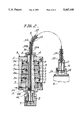
- FIG. 1 is an overall view of a first embodiment
- FIG. 2 is an enlarged vertical cross-sectional view of an important part of FIG. 1;
- FIG. 3 is an overall view of a second embodiment.
- An adjustable position fixing apparatus represented by reference numeral A in the drawings comprises a cylinder D communicating with a pressure fluid supplying machine C, such as a compressor, a pressure pump and the like, through a switching device B, an adjustable bending arm portion E, and a mount member G for an instrument F such as an endoscope or the like.
- a pressure fluid supplying machine C such as a compressor, a pressure pump and the like
- the cylinder D has a hollow interior closed by upper and lower cover plates 1 and 1. This hollow interior is divided, by two partition walls 2, 2, into three parts to define hollow chambers 3, 3.
- a reciprocating rod 4 is disposed within the cylinder D such that the rod 4 extends through the respective hollow chambers 3, 3 and also through the upper and lower cover plates 1, 1.
- Pistons 5, 5 are fixed to the reciprocating rod 4 such that they are located respectively in the hollow chambers 3, 3.
- a spring 6 is provided between the lower cover plate 1 and one of the pistons 5 in its biased condition.
- a flow channel 4a is formed longitudinally in the reciprocating rod 4 such that the channel 4a communicates with spaces 3a, 3a formed respectively between the pistons 5, 5 and the upper cover plate 1 and respective partition walls 2, 2.
- the flow channel 4a is in communication with a supply port 1a which is formed in the lower cover plate 1 and connected to the switching device B and pressure fluid supplying machine C.
- the reciprocating rod 4 is provided at its lower end with a female-threaded portion 4c which is in communication with a through-hole 4b extending in the reciprocating direction.
- An adjustment handle 8 retaining an attachment 7 is in threaded engagement with the female-threaded portion 4c.
- a receiving seat 9 is fixedly secured to an upper surface of the upper cover plate 1 of the cylinder D.
- the adjustable arm portion E is mounted on the receiving seat 9.
- the adjustable arm portion E is composed of a plurality of pieces 10.
- One end face of each piece 10 is defined as a convexly curved round surface 10a, and the other end face is defined as a concavely curved round surface 10b.
- Each piece 10 is further provided therein with a through-hole 11 opening to the end faces.
- the pieces 10 are interconnected one after another such that the convexly curved round surface 10a of one piece is in contact with the concavely curved round surface 10b of its adjacent piece.
- That piece 10 located at one end of the connected pieces 10 is in abutment relation to the receiving seat 9 of the cylinder D, while another that piece 10 located at the other end of the connected pieces 10 is in abutment relation to a receiving seat 12 which is firmly secured to the mount member G.
- the mount member G is provided with a mounting portion 13 for the instrument F such as an endoscope.
- An attachment 14 is retained by the mount member G.
- One end of a linear member 15 such as a wire is attached to the attachment 14 on the side of the mount member G.
- the linear member 15 extends through the through-holes 11 of the respective interconnected pieces 10, 10, a through-hole 9a of the receiving seat 9, and further through the through-hole 4b of the reciprocating rod 4.
- the other end of the linear member 15 is attached to the attachment 7 retained by the adjustment handle 8.
- the cylinder D is fixedly secured to a support table H such as an operation bed.
- the illustrated pedal type switching device B is turned on by a foot to supply a pressure fluid from the pressure fluid supplying machine to the respective spaces 3a, 3a via the supply port 1a of the cylinder D and the flow channel 4a of the reciprocating rod 4, so that the respective pistons 5, 5 are pressed down against the bias of the spring 6, thereby lowering the reciprocating rod 4 to pull the attachment 7 of the adjustment handle 8 to cause the linear element 15 to be tensioned.
- the switching device B For removing the fixed condition of the instrument F, the switching device B is turned off to cut off the supply of the pressure fluid. As a result, the spring 6 within the cylinder D pushes up the piston 5 to return the reciprocating rod 4. By doing this, the tension of the linear element 14 is slightly loosened to release the pressure contacting condition of the respective pieces 10, so that the mount member G is allowed to move freely.
- the adjustment handle 8 threadedly engaged with the lower end of the reciprocating rod 4 is rotated to adjust the degree of tension of the linear element 15 during the position fixing operation.
- the instrument mounted on the mount member can be fixed in a desired spatial position merely by turning on/off the switching device with one foot or one hand, it is very convenient in view of use.
- An adjustable position fixing apparatus A' of a second embodiment shown in FIG. 3 has a generally same construction as the first embodiment mentioned above.
- a stationary arm portion J and an adjustable arm portion D' are disposed between a cylinder D' firmly secured to a supporting table H' and a mount member G' on which an instrument F' is mounted.
- the cylinder D' is in communication with a pressure fluid supplying machine C' through a switching device B'.
- the cylinder D' is provided with a cylindrical stationary arm portion J erected from its upper surface. This stationary arm portion J is provided at its distal end with a receiving seat 9'.
- An adjustable arm portion E' composed of a plurality of pieces 10', 10' as in the first embodiment is disposed between the receiving seat 9' and a receiving seat 12' of the mount member G'.
- a linear element 15' extends through the stationary arm portion J and adjustable arm portion E' with its one end attached to a reciprocating rod 4' which is disposed within the cylinder D' and with its other end attached to the mount member G'. The operation is the same as the first embodiment.
- the instrument F' which is mounted on the mount member G', can of course be adjustably fixed to a desired spatial position. Furthermore, it is not essential that the interior of the cylinder is divided into three parts as in the first embodiment as long as a desired tension of the linear member can be obtained.
Abstract
Description
Claims (8)
Applications Claiming Priority (2)
| Application Number | Priority Date | Filing Date | Title |
|---|---|---|---|
| JP1993014922U JP2501030Y2 (en) | 1993-03-29 | 1993-03-29 | Flexible position fixing device for equipment |
| JP5-014922 | 1993-03-29 |
Publications (1)
| Publication Number | Publication Date |
|---|---|
| US5447149A true US5447149A (en) | 1995-09-05 |
Family
ID=11874457
Family Applications (1)
| Application Number | Title | Priority Date | Filing Date |
|---|---|---|---|
| US08/126,598 Expired - Fee Related US5447149A (en) | 1993-03-29 | 1993-08-25 | Adjustable position fixing apparatus for instrument and the like |
Country Status (4)
| Country | Link |
|---|---|
| US (1) | US5447149A (en) |
| JP (1) | JP2501030Y2 (en) |
| DE (1) | DE4409427A1 (en) |
| FR (1) | FR2702952A1 (en) |
Cited By (45)
| Publication number | Priority date | Publication date | Assignee | Title |
|---|---|---|---|---|
| WO1997004713A1 (en) * | 1995-07-26 | 1997-02-13 | Graphic Controls Corporation | Laparoscopic scope manipulator |
| WO1998049944A1 (en) * | 1997-05-02 | 1998-11-12 | Pilling Weck Incorporated | Adjustable supporting bracket having plural ball and socket joints |
| EP0987986A1 (en) * | 1997-06-11 | 2000-03-29 | Endius Incorporated | Surgical instrument |
| US6079681A (en) * | 1997-09-26 | 2000-06-27 | Picker International, Inc. | MR compatible neurosurgical positioning apparatus |
| US6165123A (en) * | 1997-08-27 | 2000-12-26 | Pinotage Llc | Controllable multi-directional positioning system |
| US6213940B1 (en) | 1996-04-26 | 2001-04-10 | United States Surgical Corporation | Surgical retractor including coil spring suture mount |
| US20020016527A1 (en) * | 1999-04-15 | 2002-02-07 | Hancock Andrew H. | Apparatus and methods for off-pump cardiac surgery |
| US6345793B1 (en) * | 2000-05-18 | 2002-02-12 | Carl Mauro | Flexible rotatable handle for transmitting tension, compression and torque forces |
| US20020077532A1 (en) * | 1999-04-15 | 2002-06-20 | Gannoe James R. | Apparatus and methods for cardiac surgery |
| US20020087048A1 (en) * | 1998-02-24 | 2002-07-04 | Brock David L. | Flexible instrument |
| US20020087148A1 (en) * | 1998-02-24 | 2002-07-04 | Brock David L. | Flexible instrument |
| US20020087166A1 (en) * | 1998-02-24 | 2002-07-04 | Brock David L. | Flexible instrument |
| US20020087049A1 (en) * | 1998-02-24 | 2002-07-04 | Brock David L. | Flexible instrument |
| US20020128662A1 (en) * | 1998-02-24 | 2002-09-12 | Brock David L. | Surgical instrument |
| US20020143319A1 (en) * | 1998-02-24 | 2002-10-03 | Brock David L. | Interchangeable surgical instrument |
| US6520495B1 (en) | 2002-01-24 | 2003-02-18 | Christopher La Mendola | Clamping device with flexible arm |
| US6565508B2 (en) | 1998-01-23 | 2003-05-20 | United States Surgical Corporation | Surgical instrument |
| US6632170B1 (en) | 2000-11-27 | 2003-10-14 | Biomec Inc. | Articulated arm for holding surgical instruments |
| US6716163B2 (en) * | 2000-11-21 | 2004-04-06 | Nabil L. Muhanna | Surgical instrument holder |
| US20040149874A1 (en) * | 2003-01-09 | 2004-08-05 | The Johns Hopkins University | Medical imaging environment compatible positioning arm |
| US20040186353A1 (en) * | 2001-08-10 | 2004-09-23 | Palermo Thomas J | Vascular retractor and methods of using same |
| US20040193146A1 (en) * | 2001-02-15 | 2004-09-30 | Endo Via Medical, Inc. | Robotically controlled surgical instruments |
| US6860878B2 (en) | 1998-02-24 | 2005-03-01 | Endovia Medical Inc. | Interchangeable instrument |
| US20050216033A1 (en) * | 2001-02-15 | 2005-09-29 | Endo Via Medical Inc. | Robotically controlled medical instrument with a flexible section |
| US6983930B1 (en) | 2004-10-28 | 2006-01-10 | Christopher Louis La Mendola | Clamping device with flexible arm |
| US20060259018A1 (en) * | 2005-04-28 | 2006-11-16 | Alexander Shilkrut | Device for holding a medical instrument |
| US20070129634A1 (en) * | 2005-10-17 | 2007-06-07 | Hickey Katherine M | Biomedical positioning and stabilization system |
| US20070233052A1 (en) * | 1998-02-24 | 2007-10-04 | Hansen Medical, Inc. | Interchangeable surgical instrument |
| US20080047064A1 (en) * | 2006-08-02 | 2008-02-28 | Theran Michael E | Surgical equipment supporting frames and attachments for same |
| US20080308688A1 (en) * | 2007-06-13 | 2008-12-18 | Kaycell Dillard | Urological Instrument Mounting Device |
| US20090149702A1 (en) * | 2007-12-07 | 2009-06-11 | Olympus Medical Systems Corp. | Holding cable, and observation apparatus and endoscope apparatus including holding cable |
| US7713190B2 (en) | 1998-02-24 | 2010-05-11 | Hansen Medical, Inc. | Flexible instrument |
| US7727185B2 (en) | 2001-02-15 | 2010-06-01 | Hansen Medical, Inc. | Coaxial catheter system |
| US7744530B2 (en) | 1998-01-23 | 2010-06-29 | Tyco Healthcare Group Lp | Surgical instrument holder |
| US7775972B2 (en) | 1998-02-24 | 2010-08-17 | Hansen Medical, Inc. | Flexible instrument |
| US7789875B2 (en) | 1998-02-24 | 2010-09-07 | Hansen Medical, Inc. | Surgical instruments |
| US7901399B2 (en) | 1998-02-24 | 2011-03-08 | Hansen Medical, Inc. | Interchangeable surgical instrument |
| US8303576B2 (en) | 1998-02-24 | 2012-11-06 | Hansen Medical, Inc. | Interchangeable surgical instrument |
| US8414505B1 (en) | 2001-02-15 | 2013-04-09 | Hansen Medical, Inc. | Catheter driver system |
| US8414598B2 (en) | 1998-02-24 | 2013-04-09 | Hansen Medical, Inc. | Flexible instrument |
| CN108463186A (en) * | 2015-10-26 | 2018-08-28 | 纽韦弗医疗设备公司 | Equipment for fixing medical treatment device and its correlation technique |
| US10368951B2 (en) | 2005-03-04 | 2019-08-06 | Auris Health, Inc. | Robotic catheter system and methods |
| US10716623B2 (en) | 2016-05-05 | 2020-07-21 | Covidien Lp | Bronchoscope coupler |
| EP3815740A4 (en) * | 2018-06-29 | 2022-03-23 | Sekisui Chemical Co., Ltd. | Plasma irradiation apparatus |
| US11419518B2 (en) | 2011-07-29 | 2022-08-23 | Auris Health, Inc. | Apparatus and methods for fiber integration and registration |
Families Citing this family (1)
| Publication number | Priority date | Publication date | Assignee | Title |
|---|---|---|---|---|
| CN109528148B (en) * | 2019-01-22 | 2023-09-26 | 绵阳美科电子设备有限责任公司 | Single swing rod endoscope clamping device |
Citations (8)
| Publication number | Priority date | Publication date | Assignee | Title |
|---|---|---|---|---|
| US3096962A (en) * | 1960-02-04 | 1963-07-09 | Meijs Pieter Johannes | Locking device for a measuring apparatus or the like |
| US3858578A (en) * | 1974-01-21 | 1975-01-07 | Pravel Wilson & Matthews | Surgical retaining device |
| US4143652A (en) * | 1976-01-29 | 1979-03-13 | Hans Meier | Surgical retaining device |
| US4457300A (en) * | 1982-06-07 | 1984-07-03 | Ohio Medical Instrument Co., Inc. | Surgical retractor |
| US4573452A (en) * | 1984-07-12 | 1986-03-04 | Greenberg I Melvin | Surgical holder for a laparoscope or the like |
| US4867404A (en) * | 1988-05-16 | 1989-09-19 | The United States Of America As Represented By The Department Of Health And Human Services | Flexible holder for a cystoscope or the like |
| US5201325A (en) * | 1989-09-01 | 1993-04-13 | Andronic Devices Ltd. | Advanced surgical retractor |
| US5284130A (en) * | 1992-06-03 | 1994-02-08 | Ratliff Jack L | Surgical instrument positioning and securing apparatus |
Family Cites Families (6)
| Publication number | Priority date | Publication date | Assignee | Title |
|---|---|---|---|---|
| DE7524814U (en) * | 1975-11-20 | Aesculap Werke Ag | Holding device for medical instruments | |
| DE1962805A1 (en) * | 1968-12-28 | 1970-08-20 | Taketoshi Mitsui | Measuring device stand |
| DE3304070A1 (en) * | 1983-02-07 | 1984-08-09 | Rheinmetall GmbH, 4000 Düsseldorf | SENSOR CARRIER |
| GB2166190A (en) * | 1984-07-06 | 1986-04-30 | Microsurgical Administrative S | Clamping arrangements |
| DE3620969A1 (en) * | 1985-06-24 | 1987-01-02 | Canon Kk | PRECISION FEED MECHANISM |
| DE3632355A1 (en) * | 1986-09-24 | 1988-04-07 | Duerkoppwerke | Pressure-medium-actuated multi-position cylinder |
-
1993
- 1993-03-29 JP JP1993014922U patent/JP2501030Y2/en not_active Expired - Lifetime
- 1993-08-25 US US08/126,598 patent/US5447149A/en not_active Expired - Fee Related
-
1994
- 1994-03-18 DE DE4409427A patent/DE4409427A1/en not_active Withdrawn
- 1994-03-25 FR FR9403514A patent/FR2702952A1/en active Pending
Patent Citations (8)
| Publication number | Priority date | Publication date | Assignee | Title |
|---|---|---|---|---|
| US3096962A (en) * | 1960-02-04 | 1963-07-09 | Meijs Pieter Johannes | Locking device for a measuring apparatus or the like |
| US3858578A (en) * | 1974-01-21 | 1975-01-07 | Pravel Wilson & Matthews | Surgical retaining device |
| US4143652A (en) * | 1976-01-29 | 1979-03-13 | Hans Meier | Surgical retaining device |
| US4457300A (en) * | 1982-06-07 | 1984-07-03 | Ohio Medical Instrument Co., Inc. | Surgical retractor |
| US4573452A (en) * | 1984-07-12 | 1986-03-04 | Greenberg I Melvin | Surgical holder for a laparoscope or the like |
| US4867404A (en) * | 1988-05-16 | 1989-09-19 | The United States Of America As Represented By The Department Of Health And Human Services | Flexible holder for a cystoscope or the like |
| US5201325A (en) * | 1989-09-01 | 1993-04-13 | Andronic Devices Ltd. | Advanced surgical retractor |
| US5284130A (en) * | 1992-06-03 | 1994-02-08 | Ratliff Jack L | Surgical instrument positioning and securing apparatus |
Cited By (81)
| Publication number | Priority date | Publication date | Assignee | Title |
|---|---|---|---|---|
| WO1997004713A1 (en) * | 1995-07-26 | 1997-02-13 | Graphic Controls Corporation | Laparoscopic scope manipulator |
| US5785643A (en) * | 1995-07-26 | 1998-07-28 | Jim Lynn | Laparoscopic scope manipulator |
| US6733445B2 (en) * | 1996-04-26 | 2004-05-11 | United States Surgical Corporation | Surgical retractor |
| US6537212B2 (en) | 1996-04-26 | 2003-03-25 | United States Surgical Corporation | Surgical retractor |
| US6213940B1 (en) | 1996-04-26 | 2001-04-10 | United States Surgical Corporation | Surgical retractor including coil spring suture mount |
| WO1998049944A1 (en) * | 1997-05-02 | 1998-11-12 | Pilling Weck Incorporated | Adjustable supporting bracket having plural ball and socket joints |
| US5899425A (en) * | 1997-05-02 | 1999-05-04 | Medtronic, Inc. | Adjustable supporting bracket having plural ball and socket joints |
| EP0987986A1 (en) * | 1997-06-11 | 2000-03-29 | Endius Incorporated | Surgical instrument |
| EP0987986A4 (en) * | 1997-06-11 | 2001-01-31 | Endius Inc | Surgical instrument |
| US6165123A (en) * | 1997-08-27 | 2000-12-26 | Pinotage Llc | Controllable multi-directional positioning system |
| US6079681A (en) * | 1997-09-26 | 2000-06-27 | Picker International, Inc. | MR compatible neurosurgical positioning apparatus |
| US7744530B2 (en) | 1998-01-23 | 2010-06-29 | Tyco Healthcare Group Lp | Surgical instrument holder |
| US6565508B2 (en) | 1998-01-23 | 2003-05-20 | United States Surgical Corporation | Surgical instrument |
| US20070233052A1 (en) * | 1998-02-24 | 2007-10-04 | Hansen Medical, Inc. | Interchangeable surgical instrument |
| US7931586B2 (en) | 1998-02-24 | 2011-04-26 | Hansen Medical, Inc. | Flexible instrument |
| US20020087169A1 (en) * | 1998-02-24 | 2002-07-04 | Brock David L. | Flexible instrument |
| US20020087049A1 (en) * | 1998-02-24 | 2002-07-04 | Brock David L. | Flexible instrument |
| US20020128662A1 (en) * | 1998-02-24 | 2002-09-12 | Brock David L. | Surgical instrument |
| US20020128633A1 (en) * | 1998-02-24 | 2002-09-12 | Brock David L. | Surgical instrument |
| US20020143319A1 (en) * | 1998-02-24 | 2002-10-03 | Brock David L. | Interchangeable surgical instrument |
| US8414598B2 (en) | 1998-02-24 | 2013-04-09 | Hansen Medical, Inc. | Flexible instrument |
| US20030050649A1 (en) * | 1998-02-24 | 2003-03-13 | Brock David L. | Surgical instrument |
| US20020087148A1 (en) * | 1998-02-24 | 2002-07-04 | Brock David L. | Flexible instrument |
| US20020087048A1 (en) * | 1998-02-24 | 2002-07-04 | Brock David L. | Flexible instrument |
| US7604642B2 (en) | 1998-02-24 | 2009-10-20 | Hansen Medical, Inc. | Interchangeable instrument |
| US7758569B2 (en) | 1998-02-24 | 2010-07-20 | Hansen Medical, Inc. | Interchangeable surgical instrument |
| US7775972B2 (en) | 1998-02-24 | 2010-08-17 | Hansen Medical, Inc. | Flexible instrument |
| US8303576B2 (en) | 1998-02-24 | 2012-11-06 | Hansen Medical, Inc. | Interchangeable surgical instrument |
| US8114097B2 (en) | 1998-02-24 | 2012-02-14 | Hansen Medical, Inc. | Flexible instrument |
| US20020087166A1 (en) * | 1998-02-24 | 2002-07-04 | Brock David L. | Flexible instrument |
| US7713190B2 (en) | 1998-02-24 | 2010-05-11 | Hansen Medical, Inc. | Flexible instrument |
| US6860878B2 (en) | 1998-02-24 | 2005-03-01 | Endovia Medical Inc. | Interchangeable instrument |
| US7371210B2 (en) | 1998-02-24 | 2008-05-13 | Hansen Medical, Inc. | Flexible instrument |
| US6949106B2 (en) | 1998-02-24 | 2005-09-27 | Endovia Medical, Inc. | Surgical instrument |
| US7918861B2 (en) | 1998-02-24 | 2011-04-05 | Hansen Medical, Inc. | Flexible instrument |
| US7905828B2 (en) | 1998-02-24 | 2011-03-15 | Hansen Medical, Inc. | Flexible instrument |
| US7789875B2 (en) | 1998-02-24 | 2010-09-07 | Hansen Medical, Inc. | Surgical instruments |
| US7090683B2 (en) | 1998-02-24 | 2006-08-15 | Hansen Medical, Inc. | Flexible instrument |
| US7901399B2 (en) | 1998-02-24 | 2011-03-08 | Hansen Medical, Inc. | Interchangeable surgical instrument |
| US7169141B2 (en) | 1998-02-24 | 2007-01-30 | Hansen Medical, Inc. | Surgical instrument |
| US7867241B2 (en) | 1998-02-24 | 2011-01-11 | Hansen Medical, Inc. | Flexible instrument |
| US7297142B2 (en) | 1998-02-24 | 2007-11-20 | Hansen Medical, Inc. | Interchangeable surgical instrument |
| US6994669B1 (en) | 1999-04-15 | 2006-02-07 | Heartport, Inc. | Apparatus and method for cardiac surgery |
| US6939297B2 (en) * | 1999-04-15 | 2005-09-06 | Heartport, Inc. | Apparatus and methods for cardiac surgery |
| US20020077532A1 (en) * | 1999-04-15 | 2002-06-20 | Gannoe James R. | Apparatus and methods for cardiac surgery |
| US20020016527A1 (en) * | 1999-04-15 | 2002-02-07 | Hancock Andrew H. | Apparatus and methods for off-pump cardiac surgery |
| US6345793B1 (en) * | 2000-05-18 | 2002-02-12 | Carl Mauro | Flexible rotatable handle for transmitting tension, compression and torque forces |
| US6716163B2 (en) * | 2000-11-21 | 2004-04-06 | Nabil L. Muhanna | Surgical instrument holder |
| US6632170B1 (en) | 2000-11-27 | 2003-10-14 | Biomec Inc. | Articulated arm for holding surgical instruments |
| US20040193146A1 (en) * | 2001-02-15 | 2004-09-30 | Endo Via Medical, Inc. | Robotically controlled surgical instruments |
| US8414505B1 (en) | 2001-02-15 | 2013-04-09 | Hansen Medical, Inc. | Catheter driver system |
| US7699835B2 (en) | 2001-02-15 | 2010-04-20 | Hansen Medical, Inc. | Robotically controlled surgical instruments |
| US7608083B2 (en) | 2001-02-15 | 2009-10-27 | Hansen Medical, Inc. | Robotically controlled medical instrument with a flexible section |
| US7727185B2 (en) | 2001-02-15 | 2010-06-01 | Hansen Medical, Inc. | Coaxial catheter system |
| US10695536B2 (en) | 2001-02-15 | 2020-06-30 | Auris Health, Inc. | Catheter driver system |
| US7744608B2 (en) | 2001-02-15 | 2010-06-29 | Hansen Medical, Inc. | Robotically controlled medical instrument |
| US8603068B2 (en) | 2001-02-15 | 2013-12-10 | Hansen Medical Inc. | Coaxial catheter system |
| US7766894B2 (en) | 2001-02-15 | 2010-08-03 | Hansen Medical, Inc. | Coaxial catheter system |
| US20080177284A1 (en) * | 2001-02-15 | 2008-07-24 | Hansen Medical, Inc. | Robotically controlled medical instrument |
| US8187229B2 (en) | 2001-02-15 | 2012-05-29 | Hansen Medical, Inc. | Coaxial catheter system |
| US7819884B2 (en) | 2001-02-15 | 2010-10-26 | Hansen Medical, Inc. | Robotically controlled medical instrument |
| US7854738B2 (en) | 2001-02-15 | 2010-12-21 | Hansen Medical, Inc. | Robotically controlled medical instrument |
| US7955316B2 (en) | 2001-02-15 | 2011-06-07 | Han Sen Medical, Inc. | Coaxial catheter system |
| US20050216033A1 (en) * | 2001-02-15 | 2005-09-29 | Endo Via Medical Inc. | Robotically controlled medical instrument with a flexible section |
| US20040186353A1 (en) * | 2001-08-10 | 2004-09-23 | Palermo Thomas J | Vascular retractor and methods of using same |
| US6520495B1 (en) | 2002-01-24 | 2003-02-18 | Christopher La Mendola | Clamping device with flexible arm |
| US20040149874A1 (en) * | 2003-01-09 | 2004-08-05 | The Johns Hopkins University | Medical imaging environment compatible positioning arm |
| US6857609B2 (en) * | 2003-01-09 | 2005-02-22 | The Johns Hopkins University | Medical imaging environment compatible positioning arm |
| US6983930B1 (en) | 2004-10-28 | 2006-01-10 | Christopher Louis La Mendola | Clamping device with flexible arm |
| US10368951B2 (en) | 2005-03-04 | 2019-08-06 | Auris Health, Inc. | Robotic catheter system and methods |
| US20060259018A1 (en) * | 2005-04-28 | 2006-11-16 | Alexander Shilkrut | Device for holding a medical instrument |
| US20070129634A1 (en) * | 2005-10-17 | 2007-06-07 | Hickey Katherine M | Biomedical positioning and stabilization system |
| US20080047064A1 (en) * | 2006-08-02 | 2008-02-28 | Theran Michael E | Surgical equipment supporting frames and attachments for same |
| US20080308688A1 (en) * | 2007-06-13 | 2008-12-18 | Kaycell Dillard | Urological Instrument Mounting Device |
| US7637466B2 (en) | 2007-06-13 | 2009-12-29 | Kaycell Dillard | Urological instrument mounting device |
| US20090149702A1 (en) * | 2007-12-07 | 2009-06-11 | Olympus Medical Systems Corp. | Holding cable, and observation apparatus and endoscope apparatus including holding cable |
| US11419518B2 (en) | 2011-07-29 | 2022-08-23 | Auris Health, Inc. | Apparatus and methods for fiber integration and registration |
| CN108463186A (en) * | 2015-10-26 | 2018-08-28 | 纽韦弗医疗设备公司 | Equipment for fixing medical treatment device and its correlation technique |
| US10716623B2 (en) | 2016-05-05 | 2020-07-21 | Covidien Lp | Bronchoscope coupler |
| USD916279S1 (en) | 2016-05-05 | 2021-04-13 | Covidien Lp | Bronchoscope coupler |
| EP3815740A4 (en) * | 2018-06-29 | 2022-03-23 | Sekisui Chemical Co., Ltd. | Plasma irradiation apparatus |
Also Published As
| Publication number | Publication date |
|---|---|
| DE4409427A1 (en) | 1994-10-06 |
| FR2702952A1 (en) | 1994-09-30 |
| JPH0674111U (en) | 1994-10-21 |
| JP2501030Y2 (en) | 1996-06-12 |
Similar Documents
| Publication | Publication Date | Title |
|---|---|---|
| US5447149A (en) | Adjustable position fixing apparatus for instrument and the like | |
| US3858578A (en) | Surgical retaining device | |
| CN101849132B (en) | Connection appliance | |
| US4865484A (en) | Single release, multiple axis coupling | |
| US8216245B2 (en) | Apparatus and method for applying sustained tension on a tether | |
| BRPI0900301B1 (en) | FIXING INSTRUMENT | |
| US5314440A (en) | Microsurgical scissor apparatus | |
| US5282409A (en) | Device for securing blades on perforation and cutting cylinders for graphic arts machinery | |
| US8328813B2 (en) | Pneumatic instrument for tissue removal | |
| EP0636226A1 (en) | Movable supporting arm | |
| JPH03118053A (en) | Controlled pressure-applying system for tissue | |
| CA2029492A1 (en) | Appliance support | |
| US4060869A (en) | Apparatus for form fitting shoes and boots | |
| EP0959720B1 (en) | Hydraulic lifting-lowering-system for a working table, a couch or lying furniture or another heavy object | |
| US4825741A (en) | Reciprocatory machine tool | |
| US6508811B2 (en) | Fastening element for a medical instrument and such medical instrument | |
| KR200208164Y1 (en) | Central lubricator with adjustable actuator | |
| DE59608048D1 (en) | Clamping element | |
| CA2248983C (en) | Hydraulic lifting-lowering-system for a working table, a couch or lying furniture or another heavy object | |
| CN213607397U (en) | Double-fold eyelid operation instrument | |
| JP2591628B2 (en) | Surgical cutter | |
| RU95107016A (en) | DEVICE FOR ENDOSURGICAL MANIPULATIONS | |
| JPS59214537A (en) | Sliding device for carriage | |
| KR940009532A (en) | Capacity Variable Slope Compressor | |
| ATE42385T1 (en) | CONTROL DEVICE AND PRESSURE ADJUSTMENT UNIT FOR THESE. |
Legal Events
| Date | Code | Title | Description |
|---|---|---|---|
| AS | Assignment |
Owner name: KABUSHIKI KAISHA EIER, JAPAN Free format text: ASSIGNMENT OF ASSIGNORS INTEREST;ASSIGNORS:KIKAWADA, TORU;KAWAI, MINORU;REEL/FRAME:006715/0814 Effective date: 19930715 |
|
| FEPP | Fee payment procedure |
Free format text: PAT HLDR NO LONGER CLAIMS SMALL ENT STAT AS SMALL BUSINESS (ORIGINAL EVENT CODE: LSM2); ENTITY STATUS OF PATENT OWNER: LARGE ENTITY |
|
| FPAY | Fee payment |
Year of fee payment: 4 |
|
| REMI | Maintenance fee reminder mailed | ||
| LAPS | Lapse for failure to pay maintenance fees | ||
| STCH | Information on status: patent discontinuation |
Free format text: PATENT EXPIRED DUE TO NONPAYMENT OF MAINTENANCE FEES UNDER 37 CFR 1.362 |
|
| FP | Lapsed due to failure to pay maintenance fee |
Effective date: 20030905 |