US5449569A - Fluid depolarized battery with improved automatic valve - Google Patents
Fluid depolarized battery with improved automatic valve Download PDFInfo
- Publication number
- US5449569A US5449569A US08/183,651 US18365194A US5449569A US 5449569 A US5449569 A US 5449569A US 18365194 A US18365194 A US 18365194A US 5449569 A US5449569 A US 5449569A
- Authority
- US
- United States
- Prior art keywords
- battery
- fluid
- valve
- cell
- valve means
- Prior art date
- Legal status (The legal status is an assumption and is not a legal conclusion. Google has not performed a legal analysis and makes no representation as to the accuracy of the status listed.)
- Expired - Lifetime
Links
Images


Classifications
-
- F—MECHANICAL ENGINEERING; LIGHTING; HEATING; WEAPONS; BLASTING
- F15—FLUID-PRESSURE ACTUATORS; HYDRAULICS OR PNEUMATICS IN GENERAL
- F15C—FLUID-CIRCUIT ELEMENTS PREDOMINANTLY USED FOR COMPUTING OR CONTROL PURPOSES
- F15C5/00—Manufacture of fluid circuit elements; Manufacture of assemblages of such elements integrated circuits
-
- H—ELECTRICITY
- H01—ELECTRIC ELEMENTS
- H01M—PROCESSES OR MEANS, e.g. BATTERIES, FOR THE DIRECT CONVERSION OF CHEMICAL ENERGY INTO ELECTRICAL ENERGY
- H01M12/00—Hybrid cells; Manufacture thereof
- H01M12/04—Hybrid cells; Manufacture thereof composed of a half-cell of the fuel-cell type and of a half-cell of the primary-cell type
- H01M12/06—Hybrid cells; Manufacture thereof composed of a half-cell of the fuel-cell type and of a half-cell of the primary-cell type with one metallic and one gaseous electrode
-
- H—ELECTRICITY
- H01—ELECTRIC ELEMENTS
- H01M—PROCESSES OR MEANS, e.g. BATTERIES, FOR THE DIRECT CONVERSION OF CHEMICAL ENERGY INTO ELECTRICAL ENERGY
- H01M50/00—Constructional details or processes of manufacture of the non-active parts of electrochemical cells other than fuel cells, e.g. hybrid cells
- H01M50/30—Arrangements for facilitating escape of gases
- H01M50/317—Re-sealable arrangements
-
- H—ELECTRICITY
- H01—ELECTRIC ELEMENTS
- H01M—PROCESSES OR MEANS, e.g. BATTERIES, FOR THE DIRECT CONVERSION OF CHEMICAL ENERGY INTO ELECTRICAL ENERGY
- H01M50/00—Constructional details or processes of manufacture of the non-active parts of electrochemical cells other than fuel cells, e.g. hybrid cells
- H01M50/30—Arrangements for facilitating escape of gases
- H01M50/375—Vent means sensitive to or responsive to temperature
-
- H—ELECTRICITY
- H01—ELECTRIC ELEMENTS
- H01M—PROCESSES OR MEANS, e.g. BATTERIES, FOR THE DIRECT CONVERSION OF CHEMICAL ENERGY INTO ELECTRICAL ENERGY
- H01M50/00—Constructional details or processes of manufacture of the non-active parts of electrochemical cells other than fuel cells, e.g. hybrid cells
- H01M50/50—Current conducting connections for cells or batteries
- H01M50/572—Means for preventing undesired use or discharge
- H01M50/574—Devices or arrangements for the interruption of current
- H01M50/583—Devices or arrangements for the interruption of current in response to current, e.g. fuses
-
- H—ELECTRICITY
- H01—ELECTRIC ELEMENTS
- H01M—PROCESSES OR MEANS, e.g. BATTERIES, FOR THE DIRECT CONVERSION OF CHEMICAL ENERGY INTO ELECTRICAL ENERGY
- H01M6/00—Primary cells; Manufacture thereof
- H01M6/04—Cells with aqueous electrolyte
- H01M6/06—Dry cells, i.e. cells wherein the electrolyte is rendered non-fluid
- H01M6/10—Dry cells, i.e. cells wherein the electrolyte is rendered non-fluid with wound or folded electrodes
- H01M6/103—Cells with electrode of only one polarity being folded or wound
-
- H—ELECTRICITY
- H01—ELECTRIC ELEMENTS
- H01M—PROCESSES OR MEANS, e.g. BATTERIES, FOR THE DIRECT CONVERSION OF CHEMICAL ENERGY INTO ELECTRICAL ENERGY
- H01M6/00—Primary cells; Manufacture thereof
- H01M6/50—Methods or arrangements for servicing or maintenance, e.g. for maintaining operating temperature
-
- H—ELECTRICITY
- H01—ELECTRIC ELEMENTS
- H01M—PROCESSES OR MEANS, e.g. BATTERIES, FOR THE DIRECT CONVERSION OF CHEMICAL ENERGY INTO ELECTRICAL ENERGY
- H01M10/00—Secondary cells; Manufacture thereof
- H01M10/05—Accumulators with non-aqueous electrolyte
-
- H—ELECTRICITY
- H01—ELECTRIC ELEMENTS
- H01M—PROCESSES OR MEANS, e.g. BATTERIES, FOR THE DIRECT CONVERSION OF CHEMICAL ENERGY INTO ELECTRICAL ENERGY
- H01M10/00—Secondary cells; Manufacture thereof
- H01M10/05—Accumulators with non-aqueous electrolyte
- H01M10/052—Li-accumulators
-
- H—ELECTRICITY
- H01—ELECTRIC ELEMENTS
- H01M—PROCESSES OR MEANS, e.g. BATTERIES, FOR THE DIRECT CONVERSION OF CHEMICAL ENERGY INTO ELECTRICAL ENERGY
- H01M2200/00—Safety devices for primary or secondary batteries
- H01M2200/10—Temperature sensitive devices
-
- H—ELECTRICITY
- H01—ELECTRIC ELEMENTS
- H01M—PROCESSES OR MEANS, e.g. BATTERIES, FOR THE DIRECT CONVERSION OF CHEMICAL ENERGY INTO ELECTRICAL ENERGY
- H01M50/00—Constructional details or processes of manufacture of the non-active parts of electrochemical cells other than fuel cells, e.g. hybrid cells
- H01M50/10—Primary casings, jackets or wrappings of a single cell or a single battery
- H01M50/116—Primary casings, jackets or wrappings of a single cell or a single battery characterised by the material
- H01M50/117—Inorganic material
- H01M50/119—Metals
-
- H—ELECTRICITY
- H01—ELECTRIC ELEMENTS
- H01M—PROCESSES OR MEANS, e.g. BATTERIES, FOR THE DIRECT CONVERSION OF CHEMICAL ENERGY INTO ELECTRICAL ENERGY
- H01M6/00—Primary cells; Manufacture thereof
- H01M6/14—Cells with non-aqueous electrolyte
- H01M6/16—Cells with non-aqueous electrolyte with organic electrolyte
-
- Y—GENERAL TAGGING OF NEW TECHNOLOGICAL DEVELOPMENTS; GENERAL TAGGING OF CROSS-SECTIONAL TECHNOLOGIES SPANNING OVER SEVERAL SECTIONS OF THE IPC; TECHNICAL SUBJECTS COVERED BY FORMER USPC CROSS-REFERENCE ART COLLECTIONS [XRACs] AND DIGESTS
- Y02—TECHNOLOGIES OR APPLICATIONS FOR MITIGATION OR ADAPTATION AGAINST CLIMATE CHANGE
- Y02E—REDUCTION OF GREENHOUSE GAS [GHG] EMISSIONS, RELATED TO ENERGY GENERATION, TRANSMISSION OR DISTRIBUTION
- Y02E60/00—Enabling technologies; Technologies with a potential or indirect contribution to GHG emissions mitigation
- Y02E60/10—Energy storage using batteries
Definitions
- This invention relates to an electrical appliance especially adapted to an improved fluid depolarized electrochemical battery comprising at least one cell, particularly those consuming oxygen from the air.
- An efficient semiconductor microactuator (a valve-on-a-chip) is placed on the case of an electrical appliance or within a sealed battery (a battery including at least one cell) so that the semiconductor microactuator is the sole means of entry of fluid depolarizer, most often air, to the battery, permitting the battery to operate when the battery is supplying electrical current to a load.
- the invention also encompasses micromachining a valve mechanism. The invention excludes-fluid depolarizer and impurities when the battery is not supplying electrical current to an electrical load to prevent the battery from discharging and losing power capacity while not in use.
- the semiconductor microactuator on the battery will break down in such a way when the battery "leaks" to minimize the damage to the device the battery is operating.
- the semiconductor microactuator acts as a pressure relief valve.
- the semiconductor microactuator may also be designed to act more optimally as a safety pressure valve or as a fuse.
- the electrical appliance and battery is rechargeable and this invention covers the combination with a recharger and with a control device to maximize the charge.
- Fluid depolarized cells exist in many types and varieties. The most common in commercial use today are metal-air depolarized cells to which this invention relates are described in McArthur et al., U.S. Pat. No. 4,547,438, Oct. 15, 1985, Zupanic, U.S. Pat. No. 4,529,673, Jul. 16, 1985, Mathews et al., U.S. Pat. No. 4,177,327, and literature cited in those patents.
- the principal advantage of zinc-air cells is that higher energy density, i.e., watts per unit of mass, can be achieved using oxygen in the air, or other Gas, as a "fluid" cathode material.
- oxygen in the air, or other Gas as a "fluid" cathode material.
- a cell of a given standard size can contain much more anode and electrolyte volume because the oxygen reactant is "stored" outside in the atmosphere. This is useful in small devices such as hearing aids, and also useful in larger cells, such as flashlight "D” or “C” cells, or in the largest of batteries such as in an electric car where much power is needed, but space used takes away from space for other uses.
- a cellular or portable phone is a good use.
- the same principle applies for a cell in which a liquid, including seawater, is a reactant, particularly for an underwater application.
- the General design and technical aspects of the cell, in a typical cell (or combination of cells, referred to as a battery) are well-known in the literature, are more specifically described in pending Application 07/886,513, now U.S. Pat. No. 5,304,431, and are described in Schumm, Jr., "Batteries," Encyclopedia of Physical Science and Technology, vol. 2, p. 387, 390, 396-97 (Academic Press, Inc. 1987)
- the metals which can be used include, for example, lead, calcium, beryllium, and lithium and alloys and mixtures of those elements.
- the use of the word "air” is employed for convenience to mean an oxygen source, which source could thus be other gas mixtures including oxygen.
- Excluding fluids and depolarizing gas prevents the cell from degrading through several processes of corrosion, moisture change and impurity entry which: a) shorten the "shelf” or storage life of the cell when it is not in use, and b) necessitate more frequent changes of the cell in an electrically powered device. Since a common use for this type of cell is for a hearing aid, it is commercially useful not to have to change the battery so frequently.
- Another common use for the cell is in a buoy at sea; exclusion of the humid, salty sea air when the cell is not operating and reduction of the frequency in changing the cell, or cells in a battery, save much labor and money.
- the control of the passage of water vapor by the valve prevents the cell from swelling or otherwise being damaged, and prevents dehydration of the cell while not operating. Also, carbon dioxide, which degrades the performance of the cell, is precluded from entering the cell when the cell is not operating.
- a more primitive approach which is effective before the cell is operated is to place a sealing tab or plug on the cell (like a pull-tab on a soda can) to be removed when the cell is put in service, admitting oxygen to the assembly.
- the sealing tab or plug in combination with an airtight assembly at least prevents the deactivation of the zinc from external sources before use (while on the "shelf"), but once activated by removing the tab, small cells must be used completely within 1 to 3 months, or the cell will have self-discharged or dried out with no useful power remaining. If the cell is operated continuously, this "once-opened/always-opened" characteristic makes little difference, but since most electrical devices are at least occasionally turned off for a period of time, a recloseable valve is important to protect the cell from degradation during that time.
- That position requires either 1) a significant loss of dimension in the length of the cell, if the cell is a cylinder, 2) a reduction in the available space of a cylindrical cell by creation of a cavity in the side of the cell, or 3) a reduction in the height of the cell to accommodate the vent cover and heating apparatus.
- a typical hearing aid battery is 1.16 centimeters ("cm.") in diameter and 0.42 cm. to 0.54 cm. thick
- a typical size "C” flashlight battery is 2.6 cm. in diameter and 5 cm. high
- a typical size “D” flashlight battery is 3.4 cm. in diameter and 6.0 centimeters high
- the valve-on-a-chip is 0.4 cm. ⁇ 0.4 cm. ⁇ 0.1 cm. in total size).
- the present invention uses significantly less space and is therefore suited to a single small cell configuration, or small electrical appliance configuration and avoids the loss in energy density either because of lower power drain or less space consumed or both.
- the present invention is intended to be used, which was not disclosed in the prior art, to act as a pressure relief valve because the cover is to the exterior of the inlet to the interior of the appliance or the cell or battery so that a plug or flap is not "trapped” against the outside container of the cell or battery.
- another objective not disclosed or intended in the prior art is to use corrosive fluid, if the semiconductor microactuator is mounted on the battery, or the inlet to the battery is juxtaposed to the valve mounted on the electrical appliance so that when the battery "leaks", the leaking fluid clogs or distorts the semiconductor microactuator and causes the cell to cease to function generally by oxygen deprivation, although it may also occur by damaging the heating element which opens the semiconductor microactuator. This more reliably causes the battery to cease to operate when it is leaking than did the devices in the prior art.
- the difficulty has been to produce a combination that preserves the energy density of the cell or electrical appliance and at the same time provides a cell that can be "dropped into” a device and function automatically to preclude fluid and impurity entry while the cell and device are not operating.
- a pressure relief characteristic and “shutdown" of the cell on malfunction or “leakage” would be helpful, but all of these functions together have not been achieved in the prior art.
- This invention overcomes the power and space requirements by using the new combination of an automatic valve of different materials and size, preferably a small electronic semiconductor microactuator, a "valve-on-a-chip", after the art of J. H. Jerman, U.S. Pat. No. 5,069,419, Dec. 3, 1991, J. H. Jerman, U.S. Pat. No. 5,271,597, Dec. 21, 1993, W. America, U.S. Pat. No. 4,969,938, Nov. 13, 1990, or a "Fluistor” semiconductor microactuator, described in Instruments and Apparatus News [IAN], October, 1993, p. 47, and Electronic Design, Nov. 1, 1993 p.
- valve-on-a-chip in conjunction with a sealed fluid depolarized electrochemical cell, especially a zinc-air cell, or mounted on an electrical appliance in such conjunction.
- the sole means of entry of depolarizing fluid is through the valve-on-a-chip.
- the combination produces a new and commercially useful invention by employing recent advances in semiconductor and micromachining technology that were not previously commercially available or invented.
- the invention contemplates the use of at least two layers, one of metal and one of semiconductor material, juxtaposed to each other.
- the invention further contemplates a modified valve design, using a grid structure inside the valve, or using the valve to power a slide or flex a grid, particularly in combination with the liquid propelled thermally responsive semiconductor microactuators.
- valve is mounted on the sealed case of the appliance, or on a sealed compartment containing the cell, and is connected in series with a switch, the valve may be "purchased once" with the electrical appliance, and an existing cell without a semiconductor microactuator used.
- the slide or grid mechanism described herein has special advantages for higher fluid flow applications, particularly for liquids which have lower aperture diffusion rates for a given volume.
- valve and cell combination works is that when the electrical device the cell is powering is "turned on”, the consequent closing of the operating circuit causes the valve to open, admitting gas, normally air, to the cell.
- the valve closes, precluding entry or exit of fluids or other impurities.
- the valve does not close as quickly as it opens, but this time is not significant compared to the many hours of time when exposure to the air would be typically closed off, and has the additional advantage of preventing "chatter", or unnecessary vibration, in certain applications.
- This valve has the additional advantage that it is conducive to a pressure relief characteristic which continues to be usable as a vent closure after relief of the pressure.
- the primary object of this invention is to combine a new type of valve with an electrical appliance or a fluid depolarized battery or cell to extend the life of the battery while preserving the energy density of the battery.
- the preferred embodiment uses a micromachined electrically activated, thermally responsive semiconductor microactuator. Impurities and depolarizing gas are excluded from the electrical appliance or battery while it is off, and when a circuit containing the battery is activated, the semiconductor microactuator opens and the battery operates.
- the primary characteristic of the combination that achieves these objectives is the self-contained, normally closed aspect with the activation internal to the valve and adjacent to the valve opening.
- the valve is solely activated internally by the closing of an electrical circuit containing the valve and is not physically actuated by any means external to the valve such as an external solenoid or magnet, external mechanical or electromechanical device, physical connection with a switch or an external heating element unless mounted on the electrical appliance itself, in which case the operating switch for the appliance activates the valve and appliance simultaneously.
- the invention can be optimized to the operational voltage or amperage of the electrical load powered by the apparatus.
- the desired voltage is less than the standard electric potential output of a zinc-air cell, and the internal resistance of the valve mechanism and a shunt resistance can reduce the voltage to a desired level.
- the resistance may be a thin film resistance deposited on the semiconductor microactuator depending on the operational characteristics desired.
- the invention is directed to a power supply in an electrical appliance composed of single cells and in batteries of cells.
- the invention is first directed to a the combination in a single cell with an electrothermally responsive valve and a resistance in parallel with such a valve that cooperate together to achieve certain energy density and performance characteristics.
- the invention is also directed to the combination of a battery or cell and the process of placing an electrothermally responsive valve in combination with the battery or cell.
- the invention is also directed to the combination of a particular type of electrothermally responsive valve: a semiconductor microactuator in a battery or cell.
- the invention is also directed to the method of regulating fluid flow in a battery.
- the invention is also directed to mounting the electrothermally responsive valve on an appliance so that standard zinc-air cells are protected and the valve cost is only paid once in connection with the manufacture of the electrical appliance structure and not for each cell or battery.
- valve can also be designed to release pressure at specified levels by varying the diaphragm characteristics.
- the cell may be "dropped-in" to existing applications without need for modification of existing electrical devices which the invention will power.
- the appliance may be modified, and standard cells used.
- the invention also may be modified to function as a fuse at a pre-determined setting.
- the invention has another objective of rechargeability and claims are directed to use with a recharger and facilities for optimizing recharge.
- Another objective is the use of the semiconductor actuator in combination with the invention to control the circulation of electrolyte fluid.
- a further objective is use of the semiconductor microactuator as a facility for varying the rate of admission of depolarizing fluid to the appliance or cell.
- FIG. 1(a) and (b) are schematic presentations of an automatic self-contained semiconductor actuator valve-on-a-chip 1(a ); the valve-on-a-chip in FIG. 1(b) is particularly modified for this application with an adjusted or special resistor on the chip to carry the main current or a resistor in parallel with the chip circuit depending on the application, current requirements and the battery configuration.
- FIG. 2 diagrammatically illustrates a miniature metal-air cell with a valve-on-a-chip to control air entry.
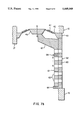
- FIG. 3 diagrammatically illustrates a larger cylindrical metal-air cell with a valve-on-a-chip to control air entry.
- FIG. 4 diagrammatically illustrates the incorporation of a valve-on-a-chip in or on the battery case to control air access to a multiple cell battery contained in the case.
- FIGS. 5 diagrammatically illustrates the contrast between the cross section of the shunt resistance added to identical FIGS. 5(a) and 1(a) and seen in FIG. 1(b) and the reduced cross-section FIGS. 5(b).
- FIG. 6 schematically illustrates the addition of a microprocessor for control purposes in series with an electrical switch.
- FIG. 7(a) diagrammatically illustrates a sliding aperture mechanism linked to a deflecting diaphragm in the closed position and FIG. 7(b) illustrates the same sliding aperture mechanism linked to a deflected diaphragm in the open position.
- FIGS. 1(a) and (b) and FIG. 2 most easily illustrate the principles of the invention.
- the invention is readily adaptable to the family of gas depolarized electrochemical cells, most of which are described in McArthur et al., U.S. Pat. No. 4,547,438, Oct. 15, 1985, Zupanic, U.S. Pat. No. 4,529,673, Jul. 16, 1985, Mathews et al., U.S. Pat. No. 4,177,327, and in literature cited in those patents.
- battery includes an array of electrochemical cells, whether connected in series or parallel, or an individual cell, unless the term cell is employed, in which case, the term battery used in the same phrase does not include an individual cell.
- This invention is useful in a one cell application.
- This invention overcomes the power and space deficiencies associated with prior art devices by using the new combination of an automatic valve made of different materials and of much smaller size through micromachining techniques, preferably a small electronic semiconductor microactuator, a "valve-on-a-chip", after the art of J. H. Jerman, U.S. Pat. No. 5,069,419, Dec. 3, 1991, J. H. Jerman, U.S. Pat. No. 5,271,597, Dec. 21, 1993, or W. America, U.S. Pat. No. 4,969,938, Nov. 13, 1990, and a "Fluistor” semiconductor microactuator, described in Instruments and Apparatus News [IAN], October, 1993, p. 47, and Electronic Design, Nov. 1, 1993 p. 34, in conjunction with a sealed fluid depolarized electrochemical cell, especially a zinc-air cell.
- the sole means of entry of depolarizing fluid is through the valve-on-a-chip.
- valves useful in this invention is broader than the Jerman or America art or the "Fluistor” semiconductor microactuator because the self-contained, micromachined valve essential to this invention can include modifications of the Jerman or America art.
- the expression "electrically activated, thermally responsive valve” therefore includes the Jerman art and like valves that include and importantly contain a cantilever deformable element.
- An alternative design in this class of electrically activated, thermally responsive valves is a valve that contains juxtaposed members secured at each of their correspondent ends which members are made of materials of different thermal expansion coefficients. When one of these elements is heated, preferably the member flexing more rapidly on application of heat, the member bends and opens a gap between the members to admit fluid.
- the term electrically activated, thermally responsive valve excludes any valve or actuator which does not contain, at least partially, the deformable element since the efficiencies of the invention cannot be obtained absent some containment. Containing the deformable element achieves comparable performance to the Jerman art which has solely transnational displacement of its deformable member as the diaphragm heating varies, which means that the valve-on-a-chip is substantially or completely non-rotational and has little or no transverse movement in the direction of flow of the depolarizing fluid, which minimizes the space usage.
- This invention also proposes a significant of each of those valves by using plates of grids, preferably with diamond shaped apertures.
- the two plates of grids when flat against each other, permit no fluid flow, but when one (or both) is flexed, the apertures allow much more fluid flow than a plate or other occlusion device covering an inlet to a valve.
- FIG. 1(a) has a perspective view of a self-contained micromachined, metal-semiconductor bilayer-actuated diaphragm valve described as a semiconductor microactuator after the art of H. Jerman, U.S. Pat. No. 5,069,419, Dec. 3, 1991 and as further described in marketing materials of the assignee of said patent, I.C. Sensors, Inc. which materials are entitled Electrically-Activated, Normally-Closed Diaphragm Valves by J. H. Jerman, the inventor of the valve-on-a-chip.
- the semiconductor microactuator pictured in FIG. 1 is approximately 4 millimeters square and 1 millimeter thick with the diaphragm 2.5 millimeters in diameter.
- a micromachined silicon valve body (36) contains a port (37) (normally the outlet port to what will be the interior of the battery), a valve seat (38), and a port (39) (normally the inlet port from the ambient atmosphere outside the battery) with that valve body mated to another micromachined silicon body (43) with a resistance heated diaphragm (40), and a metallized area (41) which is the resistance area for heating the diaphragm.
- An additional resistance if one is added, is connected to two valve terminals (44) and (45).
- a similar assembly in FIG. 1(b) to that portrayed in FIG. 1(a) has a shunt resistance element (42) added to the chip as shown to make the device more functional for situations where the battery current needed for the apparatus to be powered is greater than could be delivered through the semiconductor microactuator absent a shunt resistor.
- a thin film resistance element between the terminals could be added to the chip as shown, physically or by depositing metallized material on the semiconductor microactuator, to make the device more functional in its valve-function-only configuration.
- a resistance element of optimized value and power capacity, normally between 0.05 and 1 ohms, which resistance is much less than the internal resistance of the semiconductor microactuator, could be wired in parallel with the semiconductor microactuator as an alternative design, especially for larger battery configurations.
- America art may be similarly located in the cell or battery as the Jerman art in the prior drawing and the following drawings and vice-versa.
- the key is that there be a series connection of the valve with the cell and that the inlet of the valve correspond with the inlet of the cell and the outlet of the valve when operating admit depolarizing fluid into the cell.
- an exemplary very small gas depolarized electrochemical cell such as for a hearing aid, is comprised of a zinc anode mixture (1) disposed adjacent to and in electrical contact with a cover (2) (which is shown in FIG. 2 as being round but which can be any shape and which will be negatively charged in this embodiment), which zinc anode mixture (1) is one of the electrodes of the cell.
- a container (11) corresponding in shape to the shape of the cover (2) (which cover will be positively charged in this embodiment) surrounds a gasket (3) disposed on the inside edge of the container (11), both of which surround the cover (2), so that the gasket (3) seals the cell and separates the negatively polarized cover (2) from the positively polarized container (11).
- Another gasket (4) is disposed on the inside corner of the container (11) to locally isolate the active cathode (7) from the inside of the container (11) so that electrical output is forced to pass through the series connected semiconductor microactuator which is mounted inside the cavity (10) of the container (11), the active cathode (7) being a porous cathode layer with a conductive metal mesh or screen in it and being one of the electrodes of the cell.
- Said gasket (4) is also disposed on the inside corner of the container to hold adjacent to the active cathode (7) a separator (8) disposed between the zinc anode mixture (1) and the active cathode (7) to prevent the zinc anode mixture from contacting the active cathode, and further to hold adjacent to the active cathode in successive layers beginning adjacent to the active cathode, an electrolyte-proof membrane (5) made of a material such as Teflon (Dupont Trademark), a porous gas diffusion pad and spacer (6) with a cavity (10) in it in which to place the semiconductor microactuator, which cavity is aligned with an air inlet (9) (an aperture in the container (11)) so that the entry of air through the aperture (9) in the container (11) is controlled by the semiconductor microactuator, disposed on the inside surface of the container (11) with its inlet (39) over the aperture (9) in the container (11).
- an electrolyte-proof membrane (5) made of a material such as Teflon (D
- a gas permeable, electrolyte impermeable membrane (5) is disposed between the porous cathode layer (7) and the porous gas diffusion pad and spacer (6), which membrane (5) is made of a material such as the product polytetraflouroethylene (such as that sold as Teflon (trademark of Dupont Corporation)).
- a semiconductor microactuator is disposed on the inside surface of the container (11) in the earlier mentioned cavity in the porous gas diffusion pad and spacer (6) so that the sole means of gas communication from the exterior of the battery to the interior is through the air inlet into and through the semiconductor microactuator through the gas permeable membrane (5) to the porous cathode layer (7). Electrical connections are made from the terminals (44) and (45) of the semiconductor microactuator to the conductive member of the cathode layer (7) and to the container (11). A resistance (a thin film resistance is shown as (42)) is attached to the terminals to be in parallel with the metallized area (1). Although not shown in the figure, if a lower output of current from the battery is needed, a resistance in series with the semiconductor microactuator may be connected between the terminals of the semiconductor microactuator and the container (11).
- the closing of the circuit containing the load causes current to pass through the semiconductor microactuator, causing it to open, gas (e.g. air) to be admitted, and the gas depolarized electrochemical cell to power the apparatus containing the circuit.
- gas e.g. air
- the semiconductor microactuator functions so that when it is closed the interior of the cell is effectively sealed from the ambient, and when it is open, gas communication from the ambient to the interior of the cell case is permitted.
- the previous embodiment has the semiconductor microactuator connected between the container and the active cathode (7) which is one of the electrodes of the cell; in the next embodiment, the connection is made between the electrode of opposite polarity, the zinc anode mixture, and the container.
- FIG. 3 illustrates another preferred embodiment where the semiconductor microactuator is disposed in a larger cylindrical cell.
- the shape could also be prismatic.
- Such a cylindrical cell is comprised of a container (12) which will be negatively charged, which container (12) is round and is shaped like a shallow pan, and has a circumferential edge upturned at a right angle and then bent again at a right angle to form a second circumferential edge parallel to and outward from the center of the container. Apertures (16) are penetrated through the first upturned circumferential edge.
- An insulating cap (14) is placed adjacent to and centered on such container which cap is contained partially by such upturned circumferential edge.
- a solid contact member (13) is seated in such cap.
- the solid contact member passes through the cell seal structure to a corrosion resistant conducting collector (25) in electrical contact with the zinc anode mixture (23).
- the solid contact member (13), the corrosion resistant conducting collector (25) and the zinc anode mixture (23) form one electrode of the cell.
- a semiconductor microactuator (15) as illustrated in FIG. 1 is disposed in the corner of such container, the semiconductor microactuator being electrically connected between the solid contact member of negative polarity (13) and the container (12). Adjacent to the second outer circumferential edge of the container (12) are superposed two insulating Gaskets (18) on top of and beneath such outer circumferential edge.
- the Gasket (18) on top of the second outer circumferential edge insulates an inside structural bracing member (17) adjacent to it, which inside structural bracing member holds the solid contact member (13) in a centered position.
- the structural bracing member (17) has an inlet in it to admit depolarizing Gas to the interior of the cell over which inlet is disposed the semiconductor microactuator between the container (12) and the inside structural bracing member (1).
- the semiconductor microactuator is the only means of air access to the active portion of the cell.
- the conducting collector (25) is cylindrical and one end is seated on and attached to the solid contact member (13).
- a zinc anode mixture (23) contained within in a separator member (21) which is shaped like an open ended cylinder with the open end sealed to the edge of the sealing member (20).
- a porous cathode mixture (24) which is electrically conductive, has appropriate catalysts such as manganese dioxide, and has binders in it.
- the porous cathode mixture is contained within a corrosion resistant can (26) made of corrosion resistant metal or other material with conducting properties which can is shaped like an open-ended cylinder.
- the open end of the can (26) has a lip bent to the center of its cylindrical shape, which lip is sealed to the gasket (18) beneath the second outer circumferential edge of the container (12) and thus encloses the contents of the cell.
- a positive contact piece (27) is superposed over the closed end of the can.
- the positive contact piece (27), the can (26), and the porous cathode mixture are the electrode of the cell with opposite polarity to the electrode which includes the zinc anode mixture.
- a decorative label (22) surrounds the outside of the can (26) except on the end where the positive contact piece (27) covers the can.
- FIG. 4 shows a third embodiment comprised of an airtight non-polarized case (28) surrounding a set of connected cells (29) with apertures (30) on cells (29), having two electrodes in each cell, one of which is a positive pole connection member (32).
- the cells in this FIG. 4 are connected in series with intercell connectors (31).
- a semiconductor microactuator (33) is disposed inside the surface of the case as over an inlet (35) in the case (28) and electrically connected and disposed between at least one negative terminal of the cells (29) and the negative terminal (34) of the battery assembly.
- the inlet may have a semipermeable membrane such as Teflon (Trademark of Dupont Co.) placed to prevent non-gaseous material from entering the case (28).
- the cells may be connected in series as shown, or in parallel or some permutation thereof.
- the semiconductor microactuator when the semiconductor microactuator is in the closed position, the interior of the battery case is effectively sealed from the ambient, and when the semiconductor microactuator is in the open position, gas communication from the ambient to the interior of the battery case and into the cells is permitted.
- the cells are internally linked in series, positive to negative pole with the "end" cells having the external electrodes.
- the group of cells is sealed so that air can only enter through the vent holes.
- microprocessor chip which has voltage sensing and current sensing characteristics, and in response to either or both of those characteristics can vary the power supplied to the valve-on-a-chip, particularly to the resistance means in the valve-on-a-chip, further refinements in optimizing or regulating fluid flow can be obtained.
- Such a microprocessor chip is optimally placed in the cell adjacent to the valve-on-a-chip connected by leads to the valve-on-a-chip and container and the conductive member of the cathode layer, or placed inside the airtight non-polarized case near a terminal and the semiconductor microactuator and can be connected as shown in FIG. 6.
- FIG. 6 illustrates a load (51) connected in series with a switch (52), control mechanism (48) and a battery (49).
- the control mechanism (48) has voltage sensing and current sensing characteristics and can be a microprocessor chip which responds to voltage and current characteristics. In response to those characteristics, the control mechanism (48) can vary the power supplied to the valve-on-a-chip, particularly to the resistance in the valve-on-a-chip. By so doing, refinements in optimizing or regulating fluid flow through the actuator (in this case using the valve-on-a-chip) can be used to alter the fluid flow into the battery (49) or alternatively, to another battery.
- the actuator may actually be situated on the case and controlled by a mechanism in series or partial parallel with the battery group inside the case.
- the control and actuator mechanism can be used to optimize the load level in between subarrays of one cell or multiple cells in a battery as well as optimize recharging and discharge.
- the actuator could also be situated on the appliance and any number of permutations of array and in conjunction with a control circuit utilized.
- FIGS. 7(a) and 7(b) illustrate the principle. One face part is displaced across the other to open a plurality of holes rather than only one hole. Thus if the sliding faces are mounted in the side of a battery, a battery case or a battery compartment, much more area for fluid flow and diffusion would be made available with the small movement of the valve face. Almost any material with adequate engineering properties such as strength and corrosion resistance could be used for the slide and portion of the valve assembly.
- valve fixed part 60 is placed and sealed in an opening in container 12 and has ports or ruled openings in its face as well as guides 64 attached to hold the sliding portion 61 of the valve which sliding portion has ports or ruled openings 63 offset from those of fixed part 60 when the value is closed as shown.
- FIG. 7(a) the valve is observed in the closed position with diaphragm 40, metallic strip 41 and silicon valve body 43 attached between container part 12 and internal structural part 17.
- Valve fixed part 60 is placed and sealed in an opening in container 12 and has ports or ruled openings in its face as well as guides 64 attached to hold the sliding portion 61 of the valve which sliding portion has ports or ruled openings 63 offset from those of fixed part 60 when the value is closed as shown.
- valve is shown in the open position with diaphragm 42 bowed upward to accommodate the expansion caused by heating hence lifting the attachment part 46 pulling sliding part 61 up and causing the ports or ruled openings 63 to coincide with the ports or ruled openings 63 in fixed part 60 thus allowing outside fluid to enter the battery or battery case or battery compartment depending on the nature of container 12.
- the current carrying capacity of the resistors or the shunt circuit must be designed to fail at the desired electrical current level.
- the material chosen for the shunt or resistors will be from among possible metals or semiconductor materials such as mentioned above to yield the optimum balance of operating resistance considered against the desired failure upon overheating caused by the undesired or higher current level.
- the valve body or the shunt could also be insulated to increase the heating effect so that less current was required to cause failure. Since the resistors driving the bilayer deformation are higher in value, it is anticipated that in most cases the shunt circuit will be the fuse element intended to fail.
- the shunt resistance (42) can have a reduced cross-section portion (47) to achieve the fuse characteristic.
- the semiconductor actuator shown in FIG. 1 will function as a pressure relief device when pressure is placed on the outlet (37) side against the diaphragm.
- the semiconductor microactuator to function as a vent at a predetermined pressure it is necessary to make the semiconductor microactuator so that the desired vent pressure equals the sum of the pressure required to overcome the partial pressure of the depolarizing fluid (e.g. oxygen of the air) plus the built-in closure force in the semiconductor microactuator diaphragm on the area of the valve seat.
- the depolarizing fluid e.g. oxygen of the air
- the desired vent pressure equals the sum of the pressure required to overcome the partial pressure of the depolarizing fluid (e.g. oxygen of the air) plus the built-in closure force in the semiconductor microactuator diaphragm on the area of the valve seat.
- valve-on-a-chip For a valve-on-a-chip with a 5 micron aluminum thickness of the diaphragm and an 8 micron silicon layer, and a valve seat diameter of 400 microns, the most likely opening pressure is that required to overcome the 3 psi partial pressure of oxygen in the air if the valve-on-a-chip is employed on a metal-air battery. At a sacrifice in power required to open it, the valve-on-a-chip can be designed to require greater pressure to open.
- the above reference from I.C. Sensors, Inc. implies that for the same valve-on-a-chip the spring constant is approximately 160 dynes per micron. Referring to FIG.
- either or both the valve boss (46) and the valve seat (38) can be made so interference of these parts and deformation of the diaphragm (40) occurs when the valve-on-a-chip is assembled. Then more pressure, i.e., 160 dynes per micron of deformation during assembly, will be required to open the valve-on-a-chip to relieve the built-in pressure of the valve body.
- the deflection of this particular valve on a chip for a 50° C. temperature rise is 27.3 microns.
- the maximum bent pressure before release must overcome the 3200 dynes force (to achieve unloading of the diaphragm (40)), and the effect of the partial pressure of the depolarizing fluid (3 psi for oxygen in air). Since the area of the valve opening is only 0.0016 cm 2 , the pressure in the cell must be about 3200 dynes/0.1 cm 2 or 2,000,000 dynes/cm 2 (29 psi). Thus, the total vent opening pressure would be 32 psi.
- valve boss (46) or the valve seat (38) Any value between three and 32 psi could be achieved by making either or both the valve boss (46) or the valve seat (38) with more or less height for interference on assembly. Since cells of this type usually are designed with a low vent pressure for safety reasons, this range covers most designs typically required.
- the use of an additional layer, or circular web of material on the deformable element in the semiconductor microactuator or changing the thickness of the deformable element will accomplish the fine tuning of the pressure relief characteristic.
- the change in the construction of the moving or flexing element to accomplish the pressure relief characteristic may necessitate slight relocation or change to the placement of the heating element so that upon electrothermal actuation, the necessary fluid flow of depolarizing agent to the battery is maintained.
- valve function will be destroyed breaking the electrical circuit if the valve on a chip is in series with the power device, or precluding further admission of oxygen, eventually eliminating the power capacity of the cell or cells. Further, leakage from malfunction of the cell or battery of cells will damage the opening function of the valve-on-a-chip, minimizing damage to the apparatus powered by the cell or battery of cells. Under such circumstances, the semiconductor microactuator would act as a safety device.
- the valve-on-a-chip can be very small (4 mm. ⁇ 4 mm. ⁇ 1 mm.) and thus uses very little space and can be literally "tucked” into the cell without having to alter the exterior of the cell so radically as to require redesign of the devices that the fluid depolarized cells typically operate.
- the preferred embodiment of the invention uses a valve that has solely transnational displacement of its deformable member as the diaphragm heating varies, which means that the valve-on-a-chip is substantially or completely irrotational and has little or no transverse movement in the direction of flow of the depolarizing fluid, which minimizes the space usage.
- the semiconductor microactuator is a miniature valve literally contained in a device the size of an integrated circuit "chip".
- the semiconductor microactuator When power is supplied to the semiconductor microactuator, the semiconductor microactuator opens and allows fluid to pass while consuming little power of the cell and with minimal movement.
- the valve-on-a-chip is available for a variety of operating conditions, namely different flows and different power applications.
- the art disclosed below related to adding a resistor or resistance in parallel to the semiconductor actuator valve which gives the valve even broader use and more flexibility in this invention.
- valve-on-a-chip The dimensions of the valve-on-a-chip are approximately 4 mm ⁇ 4 mm ⁇ 1 mm. The thinnest portion of the valve-on-a-chip is perpendicular to the direction of air flow into the cell. This enables the valve-on-a-chip to be smallest in the most critical dimension to reduce space consumption in the cell and to be mounted on the exterior or interior surface of the cell container almost as if a thick paint chip is placed flat on the cell surface.
- the degree of opening of the semiconductor microactuator could be controlled by a small computer, microprocessor or other means and then the semiconductor microactuator used as a regulator of reactant air, cooling air, electrolyte circulation or other fluid flows.
- each cell delivers about 1.4 volts, in series, two cells deliver 2.8 volts etc. Because this may be above the preferred ambient operating voltage of the device being powered, a shunt resistor and the internal resistance of the semiconductor microactuator may be designed to slightly reduce the ambient operating voltage delivered by the cell. If a multiplicity of cells is connected in parallel internally and the valve-on-a-chip is connected in series with a parallel cell combination, the cells will deliver the same voltage, but more amperage or current. If the current is above the rated capacity of the semiconductor microactuator, the semiconductor microactuator must be protected.
- One way to do this is by mounting the semiconductor microactuator on the surface of the cell inside a battery of cells, connecting the semiconductor microactuator so that it is in series with a single cell added for the purpose or by inserting a low resistance shunt circuit by or on the chip to divide the current flow between the semiconductor microactuator and the shunt resistor improving the overall function of the invention.
- Another way to accomplish this in an array of cells in a battery, with or without a shunt resistor is to connect the semiconductor microactuator by one of its terminals to the critical dimension to reduce space consumption in the cell and to be mounted on the exterior or interior surface of the cell container almost as if a thick paint chip is placed flat on the cell surface.
- the degree of opening of the semiconductor microactuator could be controlled by a small computer, microprocessor or other means and then the semiconductor microactuator used as a regulator of reactant air, cooling air, electrolyte circulation or other fluid flows.
- each cell delivers about 1.4 volts, in series, two cells deliver 2.8 volts etc. Because this may be above the preferred ambient operating voltage of the device being powered, a shunt resistor and the internal resistance of the semiconductor microactuator may be designed to slightly reduce the ambient operating voltage delivered by the cell. If a multiplicity of cells is connected in parallel internally and the valve-on-a-chip is connected in series with a parallel cell combination, the cells will deliver the same voltage, but more amperage or current. If the current is above the rated capacity of the semiconductor microactuator, the semiconductor microactuator must be protected.
- One way to do this is by mounting the semiconductor microactuator on the surface of the cell inside a battery of cells, connecting the semiconductor microactuator so that it is in series with a single cell added for the purpose or by inserting a low resistance shunt circuit by or on the chip to divide the current flow between the semiconductor microactuator and the shunt resistor improving the overall function of the invention.
- Another way to accomplish this in an array of cells in a battery, with or without a shunt resistor is to connect the semiconductor microactuator by one of its terminals to the electrode of a single cell as before, but the other semiconductor microactuator terminal would be connected to the parallel combination of the cells.
- the semiconductor microactuator would still be disposed to admit air to all of the cells on the external casing of the Group of cells. More than one semiconductor microactuator can be disposed and connected for each cell, or subgroup of cells in a battery depending on the use and power being delivered.
Abstract
Description
Claims (34)
Priority Applications (3)
| Application Number | Priority Date | Filing Date | Title |
|---|---|---|---|
| US08/183,651 US5449569A (en) | 1992-05-20 | 1994-01-19 | Fluid depolarized battery with improved automatic valve |
| US08/440,079 US5541016A (en) | 1992-05-20 | 1995-05-12 | Electrical appliance with automatic valve especially for fluid depolarized electrochemical battery |
| US08/681,764 US5837394A (en) | 1992-05-20 | 1996-07-29 | Electric appliance and fluid depolarized cell with low parasitic usage microactuated valve |
Applications Claiming Priority (3)
| Application Number | Priority Date | Filing Date | Title |
|---|---|---|---|
| US07/886,513 US5304431A (en) | 1992-05-20 | 1992-05-20 | Fluid depolarized electrochemical battery with automatic valve |
| US88672592A | 1992-05-21 | 1992-05-21 | |
| US08/183,651 US5449569A (en) | 1992-05-20 | 1994-01-19 | Fluid depolarized battery with improved automatic valve |
Related Parent Applications (2)
| Application Number | Title | Priority Date | Filing Date |
|---|---|---|---|
| US07/886,513 Continuation-In-Part US5304431A (en) | 1992-05-20 | 1992-05-20 | Fluid depolarized electrochemical battery with automatic valve |
| US88672592A Continuation-In-Part | 1992-05-20 | 1992-05-21 |
Related Child Applications (2)
| Application Number | Title | Priority Date | Filing Date |
|---|---|---|---|
| US08/440,079 Division US5541016A (en) | 1992-05-20 | 1995-05-12 | Electrical appliance with automatic valve especially for fluid depolarized electrochemical battery |
| US08/440,079 Continuation-In-Part US5541016A (en) | 1992-05-20 | 1995-05-12 | Electrical appliance with automatic valve especially for fluid depolarized electrochemical battery |
Publications (1)
| Publication Number | Publication Date |
|---|---|
| US5449569A true US5449569A (en) | 1995-09-12 |
Family
ID=27128801
Family Applications (1)
| Application Number | Title | Priority Date | Filing Date |
|---|---|---|---|
| US08/183,651 Expired - Lifetime US5449569A (en) | 1992-05-20 | 1994-01-19 | Fluid depolarized battery with improved automatic valve |
Country Status (1)
| Country | Link |
|---|---|
| US (1) | US5449569A (en) |
Cited By (32)
| Publication number | Priority date | Publication date | Assignee | Title |
|---|---|---|---|---|
| US5541016A (en) * | 1992-05-20 | 1996-07-30 | Schumm, Jr.; Brooke | Electrical appliance with automatic valve especially for fluid depolarized electrochemical battery |
| US5984859A (en) * | 1993-01-25 | 1999-11-16 | Lesinski; S. George | Implantable auditory system components and system |
| US6074775A (en) * | 1998-04-02 | 2000-06-13 | The Procter & Gamble Company | Battery having a built-in controller |
| WO2000036696A1 (en) * | 1998-12-18 | 2000-06-22 | Aer Energy Resources, Inc. | Air manager systems for metal-air batteries utilizing a diaphragm or bellows |
| US6118248A (en) * | 1998-04-02 | 2000-09-12 | The Procter & Gamble Company | Battery having a built-in controller to extend battery service run time |
| US6163131A (en) * | 1998-04-02 | 2000-12-19 | The Procter & Gamble Company | Battery having a built-in controller |
| WO2001009520A1 (en) | 1999-07-30 | 2001-02-08 | The Board Of Trustees Of The University Of Illinois | Microvalve for controlling fluid flow |
| US6198250B1 (en) | 1998-04-02 | 2001-03-06 | The Procter & Gamble Company | Primary battery having a built-in controller to extend battery run time |
| US6261709B1 (en) * | 1998-03-06 | 2001-07-17 | Rayovac Corporation | Air depolarized electrochemical cell having mass-control chamber in anode |
| US6368738B1 (en) | 1998-03-06 | 2002-04-09 | Rayovac Corporation | Air depolarized electrochemical cell |
| US6660418B1 (en) | 1998-06-15 | 2003-12-09 | Aer Energy Resources, Inc. | Electrical device with removable enclosure for electrochemical cell |
| US20040081328A1 (en) * | 1996-03-14 | 2004-04-29 | Sarnoff Corporation | Hearing aid |
| US6759159B1 (en) | 2000-06-14 | 2004-07-06 | The Gillette Company | Synthetic jet for admitting and expelling reactant air |
| US20040159813A1 (en) * | 1999-07-30 | 2004-08-19 | The Procter & Gamble Company | Microvalve for controlling fluid flow |
| US6824915B1 (en) | 2000-06-12 | 2004-11-30 | The Gillette Company | Air managing systems and methods for gas depolarized power supplies utilizing a diaphragm |
| US6835491B2 (en) | 1998-04-02 | 2004-12-28 | The Board Of Trustees Of The University Of Illinois | Battery having a built-in controller |
| US20050016605A1 (en) * | 1999-07-30 | 2005-01-27 | Sherman Faiz Feisal | Microvalve for controlling fluid flow |
| US20080085443A1 (en) * | 2006-04-11 | 2008-04-10 | Somerville John M | Fluid Manager Including a Lever and a Battery Including the Same |
| US20080096074A1 (en) * | 2006-10-23 | 2008-04-24 | Eveready Battery Company, Inc. | Electrochemical air cell batteries with air flow channels |
| US7378168B2 (en) | 2004-10-29 | 2008-05-27 | Eveready Battery Company, Inc. | Fluid regulating microvalve assembly for fluid consuming cells |
| US20080254345A1 (en) * | 2007-04-11 | 2008-10-16 | Broburg Gregory W | Battery and fluid regulating system having chassis with molded electronics |
| US20080254340A1 (en) * | 2007-04-11 | 2008-10-16 | Blakey David M | Battery having fluid regulator with pressure equalization |
| US20080254346A1 (en) * | 2007-04-11 | 2008-10-16 | Burstall Oliver W | Battery having fluid regulator with rotating valve |
| US20080254330A1 (en) * | 2007-04-11 | 2008-10-16 | Jones Steven D | Battery fluid manager using shape memory alloy components with different actuation temperatures |
| US7866342B2 (en) | 2002-12-18 | 2011-01-11 | Vapor Technologies, Inc. | Valve component for faucet |
| US7866343B2 (en) | 2002-12-18 | 2011-01-11 | Masco Corporation Of Indiana | Faucet |
| US8123967B2 (en) | 2005-08-01 | 2012-02-28 | Vapor Technologies Inc. | Method of producing an article having patterned decorative coating |
| US8220489B2 (en) | 2002-12-18 | 2012-07-17 | Vapor Technologies Inc. | Faucet with wear-resistant valve component |
| US8329357B2 (en) | 2007-09-24 | 2012-12-11 | Eveready Battery Company, Inc. | Battery having fluid manager and sliding valve with friction reduction members |
| WO2013119834A1 (en) * | 2012-02-10 | 2013-08-15 | Northeastern University | Sealable microvalve that can be repeatedly opened and sealed |
| US8555921B2 (en) | 2002-12-18 | 2013-10-15 | Vapor Technologies Inc. | Faucet component with coating |
| CN103794747A (en) * | 2012-11-05 | 2014-05-14 | 九能京通(天津)新能源科技有限公司 | Zinc air battery monomer connection structure |
Citations (17)
| Publication number | Priority date | Publication date | Assignee | Title |
|---|---|---|---|---|
| US2468430A (en) * | 1943-04-12 | 1949-04-26 | Hartford Nat Bank & Trust Co | Casing with pushbutton valve for air depolarized cells |
| US3746580A (en) * | 1971-08-19 | 1973-07-17 | Esb Inc | Gas depolarizable galvanic cell |
| US4011366A (en) * | 1975-05-22 | 1977-03-08 | United Kingdom Atomic Energy Authority | Electric cells |
| US4035552A (en) * | 1976-07-23 | 1977-07-12 | Gte Laboratories Incorporated | Electrochemical cell |
| US4039728A (en) * | 1974-08-10 | 1977-08-02 | Institut Francais Du Petrole | Automatic device for opening and closing the comburent inlet and outlet ports of a fuel cell |
| US4074022A (en) * | 1975-11-21 | 1978-02-14 | Saft-Societe Des Accumulateurs Fixes Et De Traction | Casing of an electric cell |
| US4177327A (en) * | 1978-11-20 | 1979-12-04 | P. R. Mallory & Co. Inc. | Metal-air battery having electrically operated air access vent cover |
| US4189526A (en) * | 1978-05-05 | 1980-02-19 | Gould Inc. | Metal/oxygen cells and method for optimizing the active life properties thereof |
| US4529673A (en) * | 1982-07-30 | 1985-07-16 | Union Carbide Corporation | Electrochemical cell having a safety vent closure |
| US4547438A (en) * | 1984-12-18 | 1985-10-15 | Duracell Inc. | Battery assembly |
| US4894295A (en) * | 1988-09-14 | 1990-01-16 | Cheiky Michael C | Metal-alloy air battery |
| US4913983A (en) * | 1988-09-13 | 1990-04-03 | Dreisbach Electromotive, Inc. | Metal-air battery power supply |
| US5069419A (en) * | 1989-06-23 | 1991-12-03 | Ic Sensors Inc. | Semiconductor microactuator |
| US5158838A (en) * | 1989-03-06 | 1992-10-27 | Oddvar Bjordal | Method for preventing formation of calcareous deposits on seawater battery cathodes |
| US5258239A (en) * | 1992-04-22 | 1993-11-02 | Brother Kogyo Kabushiki Kaisha | Metal-air cell having a piezoelectric air-supply pump |
| US5271597A (en) * | 1992-05-29 | 1993-12-21 | Ic Sensors, Inc. | Bimetallic diaphragm with split hinge for microactuator |
| US5304431A (en) * | 1992-05-20 | 1994-04-19 | Schumm Jr Brooke | Fluid depolarized electrochemical battery with automatic valve |
-
1994
- 1994-01-19 US US08/183,651 patent/US5449569A/en not_active Expired - Lifetime
Patent Citations (17)
| Publication number | Priority date | Publication date | Assignee | Title |
|---|---|---|---|---|
| US2468430A (en) * | 1943-04-12 | 1949-04-26 | Hartford Nat Bank & Trust Co | Casing with pushbutton valve for air depolarized cells |
| US3746580A (en) * | 1971-08-19 | 1973-07-17 | Esb Inc | Gas depolarizable galvanic cell |
| US4039728A (en) * | 1974-08-10 | 1977-08-02 | Institut Francais Du Petrole | Automatic device for opening and closing the comburent inlet and outlet ports of a fuel cell |
| US4011366A (en) * | 1975-05-22 | 1977-03-08 | United Kingdom Atomic Energy Authority | Electric cells |
| US4074022A (en) * | 1975-11-21 | 1978-02-14 | Saft-Societe Des Accumulateurs Fixes Et De Traction | Casing of an electric cell |
| US4035552A (en) * | 1976-07-23 | 1977-07-12 | Gte Laboratories Incorporated | Electrochemical cell |
| US4189526A (en) * | 1978-05-05 | 1980-02-19 | Gould Inc. | Metal/oxygen cells and method for optimizing the active life properties thereof |
| US4177327A (en) * | 1978-11-20 | 1979-12-04 | P. R. Mallory & Co. Inc. | Metal-air battery having electrically operated air access vent cover |
| US4529673A (en) * | 1982-07-30 | 1985-07-16 | Union Carbide Corporation | Electrochemical cell having a safety vent closure |
| US4547438A (en) * | 1984-12-18 | 1985-10-15 | Duracell Inc. | Battery assembly |
| US4913983A (en) * | 1988-09-13 | 1990-04-03 | Dreisbach Electromotive, Inc. | Metal-air battery power supply |
| US4894295A (en) * | 1988-09-14 | 1990-01-16 | Cheiky Michael C | Metal-alloy air battery |
| US5158838A (en) * | 1989-03-06 | 1992-10-27 | Oddvar Bjordal | Method for preventing formation of calcareous deposits on seawater battery cathodes |
| US5069419A (en) * | 1989-06-23 | 1991-12-03 | Ic Sensors Inc. | Semiconductor microactuator |
| US5258239A (en) * | 1992-04-22 | 1993-11-02 | Brother Kogyo Kabushiki Kaisha | Metal-air cell having a piezoelectric air-supply pump |
| US5304431A (en) * | 1992-05-20 | 1994-04-19 | Schumm Jr Brooke | Fluid depolarized electrochemical battery with automatic valve |
| US5271597A (en) * | 1992-05-29 | 1993-12-21 | Ic Sensors, Inc. | Bimetallic diaphragm with split hinge for microactuator |
Non-Patent Citations (15)
| Title |
|---|
| "Electrothermal Actuators Vie with Electromagnets and Solenoids", Product Engineering, Oct. 1975, pp. 19-21. |
| "Relay has no Coil-Actuators Heated to Open/Close Contacts", Automation, Aug. 1975, p. 17. |
| Electronic Design, Nov. 1, 1993, p. 34. * |
| Electrothermal Actuators Vie with Electromagnets and Solenoids , Product Engineering, Oct. 1975, pp. 19 21. * |
| I.C. Sensors Marketing Literature and Product Catalog, Mar. 1992 title: Electrically Activated, Normally Closed Diaphragm Valves. * |
| I.C. Sensors Marketing Literature and Product Catalog, Mar. 1992--title: Electrically Activated, Normally Closed Diaphragm Valves. |
| Instruments and Apparatus News [IAN], Oct. 1993, p. 47. |
| Instruments and Apparatus News IAN , Oct. 1993, p. 47. * |
| Power Sources 4, Research and Development in Non Mechanical Elect. Power Sources, Proceedings of the 8th International Symposium held at Brighton, Sep. 1972, E. by D H Collins, (Oriel Press). * |
| Power Sources 4, Research and Development in Non-Mechanical Elect. Power Sources, Proceedings of the 8th International Symposium held at Brighton, Sep. 1972, E. by D H Collins, (Oriel Press). |
| Relay has no Coil Actuators Heated to Open/Close Contacts , Automation, Aug. 1975, p. 17. * |
| Schumm, Jr., "Batteries", Encyclopedia of Physical Sciences and Technology, vol. 2, pp. 387, 396-397 (Academic Press 1987) p. 390 (month n/a). |
| Schumm, Jr., Batteries , Encyclopedia of Physical Sciences and Technology, vol. 2, pp. 387, 396 397 (Academic Press 1987) p. 390 (month n/a). * |
| Tuck, Modern Battery Technology, Ellis Horwood Series in Applied Sciences and Industrial Technology (London N.Y. 1991) pp. 126, 128, 129, 135 138, 161 162, 166 167, 187 188. (month n/a). * |
| Tuck, Modern Battery Technology, Ellis Horwood Series in Applied Sciences and Industrial Technology (London N.Y. 1991) pp. 126, 128, 129, 135-138, 161-162, 166-167, 187-188. (month n/a). |
Cited By (64)
| Publication number | Priority date | Publication date | Assignee | Title |
|---|---|---|---|---|
| US5541016A (en) * | 1992-05-20 | 1996-07-30 | Schumm, Jr.; Brooke | Electrical appliance with automatic valve especially for fluid depolarized electrochemical battery |
| US5984859A (en) * | 1993-01-25 | 1999-11-16 | Lesinski; S. George | Implantable auditory system components and system |
| US7987977B2 (en) * | 1996-03-14 | 2011-08-02 | Sarnoff Corporation | Hearing aid package |
| US7536023B2 (en) | 1996-03-14 | 2009-05-19 | Sarnoff Corporation | Hearing aid |
| US20040240695A1 (en) * | 1996-03-14 | 2004-12-02 | Sarnoff Corporation | Hearing aid |
| US20040081328A1 (en) * | 1996-03-14 | 2004-04-29 | Sarnoff Corporation | Hearing aid |
| US6261709B1 (en) * | 1998-03-06 | 2001-07-17 | Rayovac Corporation | Air depolarized electrochemical cell having mass-control chamber in anode |
| US6368738B1 (en) | 1998-03-06 | 2002-04-09 | Rayovac Corporation | Air depolarized electrochemical cell |
| US6835491B2 (en) | 1998-04-02 | 2004-12-28 | The Board Of Trustees Of The University Of Illinois | Battery having a built-in controller |
| US6198250B1 (en) | 1998-04-02 | 2001-03-06 | The Procter & Gamble Company | Primary battery having a built-in controller to extend battery run time |
| US6118248A (en) * | 1998-04-02 | 2000-09-12 | The Procter & Gamble Company | Battery having a built-in controller to extend battery service run time |
| US6074775A (en) * | 1998-04-02 | 2000-06-13 | The Procter & Gamble Company | Battery having a built-in controller |
| US6163131A (en) * | 1998-04-02 | 2000-12-19 | The Procter & Gamble Company | Battery having a built-in controller |
| US6660418B1 (en) | 1998-06-15 | 2003-12-09 | Aer Energy Resources, Inc. | Electrical device with removable enclosure for electrochemical cell |
| US6475658B1 (en) | 1998-12-18 | 2002-11-05 | Aer Energy Resources, Inc. | Air manager systems for batteries utilizing a diaphragm or bellows |
| WO2000036696A1 (en) * | 1998-12-18 | 2000-06-22 | Aer Energy Resources, Inc. | Air manager systems for metal-air batteries utilizing a diaphragm or bellows |
| WO2001009520A1 (en) | 1999-07-30 | 2001-02-08 | The Board Of Trustees Of The University Of Illinois | Microvalve for controlling fluid flow |
| US20040159813A1 (en) * | 1999-07-30 | 2004-08-19 | The Procter & Gamble Company | Microvalve for controlling fluid flow |
| WO2001009521A1 (en) | 1999-07-30 | 2001-02-08 | The Procter & Gamble Company | Microvalve for controlling fluid flow |
| US20050016605A1 (en) * | 1999-07-30 | 2005-01-27 | Sherman Faiz Feisal | Microvalve for controlling fluid flow |
| US6887615B1 (en) | 1999-07-30 | 2005-05-03 | The Procter & Gamble Company | Microvalve for controlling fluid flow |
| US6935609B2 (en) | 1999-07-30 | 2005-08-30 | The Procter & Gamble Company | Microvalve for controlling fluid flow |
| US20050211313A1 (en) * | 1999-07-30 | 2005-09-29 | The Procter & Gamble Company | Microvalve for controlling fluid flow |
| US6962170B1 (en) | 1999-07-30 | 2005-11-08 | The Procter & Gamble Company | Microvalve for controlling fluid flow |
| US6981520B2 (en) | 1999-07-30 | 2006-01-03 | The Procter & Gamble Company | Microvalve for controlling fluid flow |
| US7066205B2 (en) | 1999-07-30 | 2006-06-27 | The Procter & Gamble Company | Microvalve for controlling fluid flow |
| US6824915B1 (en) | 2000-06-12 | 2004-11-30 | The Gillette Company | Air managing systems and methods for gas depolarized power supplies utilizing a diaphragm |
| US6759159B1 (en) | 2000-06-14 | 2004-07-06 | The Gillette Company | Synthetic jet for admitting and expelling reactant air |
| US9388910B2 (en) | 2002-12-18 | 2016-07-12 | Delta Faucet Company | Faucet component with coating |
| US8555921B2 (en) | 2002-12-18 | 2013-10-15 | Vapor Technologies Inc. | Faucet component with coating |
| US8220489B2 (en) | 2002-12-18 | 2012-07-17 | Vapor Technologies Inc. | Faucet with wear-resistant valve component |
| US8118055B2 (en) | 2002-12-18 | 2012-02-21 | Vapor Technologies Inc. | Valve component for faucet |
| US9909677B2 (en) | 2002-12-18 | 2018-03-06 | Delta Faucet Company | Faucet component with coating |
| US7866343B2 (en) | 2002-12-18 | 2011-01-11 | Masco Corporation Of Indiana | Faucet |
| US7866342B2 (en) | 2002-12-18 | 2011-01-11 | Vapor Technologies, Inc. | Valve component for faucet |
| US7378168B2 (en) | 2004-10-29 | 2008-05-27 | Eveready Battery Company, Inc. | Fluid regulating microvalve assembly for fluid consuming cells |
| US8123967B2 (en) | 2005-08-01 | 2012-02-28 | Vapor Technologies Inc. | Method of producing an article having patterned decorative coating |
| US20080096069A1 (en) * | 2006-04-11 | 2008-04-24 | Bailey John C | Fluid Manager Using Two Shape Memory Alloy Components and a Battery Including the Same |
| US20080090135A1 (en) * | 2006-04-11 | 2008-04-17 | Wu James X | Fluid Manager Including Electrical Contacts and a Battery Including the Same |
| US20080085443A1 (en) * | 2006-04-11 | 2008-04-10 | Somerville John M | Fluid Manager Including a Lever and a Battery Including the Same |
| US20080085444A1 (en) * | 2006-04-11 | 2008-04-10 | Langan Richard A | Battery Including a Fluid Manager Mounted Internal to Cell |
| US20080085436A1 (en) * | 2006-04-11 | 2008-04-10 | Langan Richard A | Fluid Manager Having a Chassis-Mounted Actuator and a Battery Including the Same |
| US7732088B2 (en) | 2006-04-11 | 2010-06-08 | Eveready Battery Company, Inc. | Fluid manager including a lever and a battery including the same |
| US20080096067A1 (en) * | 2006-04-11 | 2008-04-24 | Langan Richard A | Battery Including a Fluid Manager |
| US7740976B2 (en) | 2006-04-11 | 2010-06-22 | Eveready Battery Company, Inc. | Fluid manager having a chassis-mounted actuator and a battery including the same |
| US20080096082A1 (en) * | 2006-04-11 | 2008-04-24 | Langan Richard A | Battery Including a Fluid Manager Mounted External to Cell |
| US7833650B2 (en) | 2006-04-11 | 2010-11-16 | Eveready Battery Company, Inc. | Battery including a fluid manager |
| US7837744B2 (en) | 2006-04-11 | 2010-11-23 | Eveready Battery Company, Inc. | Battery including a fluid manager mounted internal to cell |
| US7855006B2 (en) | 2006-04-11 | 2010-12-21 | Eveready Battery Company, Inc. | Fluid manager including electrical contacts and a battery including the same |
| US7858226B2 (en) | 2006-04-11 | 2010-12-28 | Eveready Battery Company, Inc. | Battery including a fluid manager mounted external to cell |
| US7972718B2 (en) | 2006-04-11 | 2011-07-05 | Eveready Battery Company, Inc. | Fluid manager using two shape memory alloy components and a battery including the same |
| US20080096074A1 (en) * | 2006-10-23 | 2008-04-24 | Eveready Battery Company, Inc. | Electrochemical air cell batteries with air flow channels |
| US7618739B2 (en) | 2007-04-11 | 2009-11-17 | Eveready Battery Co., Inc. | Battery and fluid regulating system having chassis with molded electronics |
| US20080254340A1 (en) * | 2007-04-11 | 2008-10-16 | Blakey David M | Battery having fluid regulator with pressure equalization |
| US7833649B2 (en) | 2007-04-11 | 2010-11-16 | Eveready Battery Company, Inc. | Battery fluid manager using shape memory alloy components with different actuation temperatures |
| US7732089B2 (en) | 2007-04-11 | 2010-06-08 | Eveready Battery Company, Inc. | Battery having fluid regulator with rotating valve |
| US20080254330A1 (en) * | 2007-04-11 | 2008-10-16 | Jones Steven D | Battery fluid manager using shape memory alloy components with different actuation temperatures |
| US20080254345A1 (en) * | 2007-04-11 | 2008-10-16 | Broburg Gregory W | Battery and fluid regulating system having chassis with molded electronics |
| US20080254346A1 (en) * | 2007-04-11 | 2008-10-16 | Burstall Oliver W | Battery having fluid regulator with rotating valve |
| US7632585B2 (en) | 2007-04-11 | 2009-12-15 | Eveready Battery Co., Inc. | Battery having fluid regulator with pressure equalization |
| US8329357B2 (en) | 2007-09-24 | 2012-12-11 | Eveready Battery Company, Inc. | Battery having fluid manager and sliding valve with friction reduction members |
| US9546743B2 (en) | 2012-02-10 | 2017-01-17 | Northeastern University | Sealable microvalve that can be repeatedly opened and sealed |
| WO2013119834A1 (en) * | 2012-02-10 | 2013-08-15 | Northeastern University | Sealable microvalve that can be repeatedly opened and sealed |
| CN103794747A (en) * | 2012-11-05 | 2014-05-14 | 九能京通(天津)新能源科技有限公司 | Zinc air battery monomer connection structure |
Similar Documents
| Publication | Publication Date | Title |
|---|---|---|
| US5449569A (en) | Fluid depolarized battery with improved automatic valve | |
| US5304431A (en) | Fluid depolarized electrochemical battery with automatic valve | |
| US5541016A (en) | Electrical appliance with automatic valve especially for fluid depolarized electrochemical battery | |
| US5837394A (en) | Electric appliance and fluid depolarized cell with low parasitic usage microactuated valve | |
| US6962170B1 (en) | Microvalve for controlling fluid flow | |
| JP4391016B2 (en) | Current breaker for electrochemical battery | |
| EP2135322B1 (en) | Battery fluid manager using shape memory alloy components with different actuation temperatures | |
| EP2156509B1 (en) | A battery having fluid regulator with rotating valve | |
| KR20090032028A (en) | Battery including a fluid manager mounted external to cell | |
| WO2001009520A1 (en) | Microvalve for controlling fluid flow | |
| JP2002515164A (en) | Small battery battery | |
| US4957830A (en) | Rechargeable metal oxide-hydrogen battery | |
| JP2008519398A (en) | Fluid-regulated microvalve assembly for fluid-consuming batteries | |
| US5171647A (en) | Hydrogen containment cover assembly for sealing the cell can of a rechargeable electrochemical hydrogen storage cell | |
| US20110269030A1 (en) | Oxygen-Consuming Battery with Improved High Rate Capability | |
| EP2143165A1 (en) | Battery having fluid regulator with pressure equalization | |
| EP2198473A1 (en) | Battery having fluid manager and sliding valve with friction reduction members | |
| JP2002324564A (en) | Fuel cell device and control method therefor | |
| US20120208102A1 (en) | Fluid regulating microvalve assembly for fluid consuming cells with spring-like shape-retaining aperture cover | |
| US7914936B2 (en) | Fuel cell system | |
| US6893771B2 (en) | Battery assembly | |
| KR20030032540A (en) | Safety valve device and secondary battery applying such | |
| KR101130097B1 (en) | Electric energy storage device having safety device | |
| JP3527548B2 (en) | Safety device for secondary battery and non-aqueous electrolyte secondary battery with safety device | |
| JP3539620B2 (en) | Rechargeable battery |
Legal Events
| Date | Code | Title | Description |
|---|---|---|---|
| STCF | Information on status: patent grant |
Free format text: PATENTED CASE |
|
| AS | Assignment |
Owner name: SCHUMM, ELIZABETH, OHIO Free format text: ASSIGNMENT OF ASSIGNORS INTEREST;ASSIGNOR:SCHUMM JR., BROOKE;REEL/FRAME:009306/0771 Effective date: 19980706 Owner name: SCHUMM, ELIZABETH, OHIO Free format text: SECURITY INTEREST;ASSIGNORS:SCHUMM, BROOKE III;SCHUMM, KARI J.;REEL/FRAME:009342/0089 Effective date: 19980706 Owner name: SCHUMM, BROOKE JR., OHIO Free format text: SECURITY INTEREST;ASSIGNORS:SCHUMM, BROOKE III;SCHUMM, KARI J.;REEL/FRAME:009342/0089 Effective date: 19980706 Owner name: SCHUMM JR., BROOKE, OHIO Free format text: ASSIGNMENT OF ASSIGNORS INTEREST;ASSIGNOR:SCHUMM JR., BROOKE;REEL/FRAME:009306/0771 Effective date: 19980706 Owner name: SCHUMM III, BROOKE, MARYLAND Free format text: ASSIGNMENT OF ASSIGNORS INTEREST;ASSIGNOR:SCHUMM JR., BROOKE;REEL/FRAME:009306/0771 Effective date: 19980706 Owner name: SCHUMM, KARI J., MARYLAND Free format text: ASSIGNMENT OF ASSIGNORS INTEREST;ASSIGNOR:SCHUMM JR., BROOKE;REEL/FRAME:009306/0771 Effective date: 19980706 |
|
| FPAY | Fee payment |
Year of fee payment: 4 |
|
| REMI | Maintenance fee reminder mailed | ||
| FPAY | Fee payment |
Year of fee payment: 8 |
|
| SULP | Surcharge for late payment |
Year of fee payment: 7 |
|
| AS | Assignment |
Owner name: EVEREADY BATTERY COMPANY, INC., MISSOURI Free format text: ASSIGNMENT OF ASSIGNORS INTEREST;ASSIGNORS:SCHUMM, BROOKE JR.;SCHUMM, ELIZABETH;SCHUMM, BROOKE III;AND OTHERS;REEL/FRAME:017262/0732 Effective date: 20060208 |
|
| FEPP | Fee payment procedure |
Free format text: PAT HOLDER NO LONGER CLAIMS SMALL ENTITY STATUS, ENTITY STATUS SET TO UNDISCOUNTED (ORIGINAL EVENT CODE: STOL); ENTITY STATUS OF PATENT OWNER: LARGE ENTITY |
|
| FEPP | Fee payment procedure |
Free format text: ENTITY STATUS SET TO UNDISCOUNTED (ORIGINAL EVENT CODE: BIG.); ENTITY STATUS OF PATENT OWNER: LARGE ENTITY |
|
| FPAY | Fee payment |
Year of fee payment: 12 |
|
| AS | Assignment |
Owner name: SCHUMM, BROOKE, III, MARYLAND Free format text: ASSIGNMENT OF ASSIGNORS INTEREST;ASSIGNOR:EVEREADY BATTERY COMPANY, INC.;REEL/FRAME:024785/0995 Effective date: 20100722 Owner name: SCHUMM, KARI J, MARYLAND Free format text: ASSIGNMENT OF ASSIGNORS INTEREST;ASSIGNOR:EVEREADY BATTERY COMPANY, INC.;REEL/FRAME:024785/0995 Effective date: 20100722 Owner name: SCHUMM, BROOKE, JR, OHIO Free format text: ASSIGNMENT OF ASSIGNORS INTEREST;ASSIGNOR:EVEREADY BATTERY COMPANY, INC.;REEL/FRAME:024785/0995 Effective date: 20100722 Owner name: SCHUMM, ELIZABETH, OHIO Free format text: ASSIGNMENT OF ASSIGNORS INTEREST;ASSIGNOR:EVEREADY BATTERY COMPANY, INC.;REEL/FRAME:024785/0995 Effective date: 20100722 |