US5458371A - Crimp-formed joint housings for air bag inflators - Google Patents
Crimp-formed joint housings for air bag inflators Download PDFInfo
- Publication number
- US5458371A US5458371A US08/330,344 US33034494A US5458371A US 5458371 A US5458371 A US 5458371A US 33034494 A US33034494 A US 33034494A US 5458371 A US5458371 A US 5458371A
- Authority
- US
- United States
- Prior art keywords
- side wall
- housing
- ignition
- wall
- annular
- Prior art date
- Legal status (The legal status is an assumption and is not a legal conclusion. Google has not performed a legal analysis and makes no representation as to the accuracy of the status listed.)
- Expired - Lifetime
Links
Images

Classifications
-
- B—PERFORMING OPERATIONS; TRANSPORTING
- B60—VEHICLES IN GENERAL
- B60R—VEHICLES, VEHICLE FITTINGS, OR VEHICLE PARTS, NOT OTHERWISE PROVIDED FOR
- B60R21/00—Arrangements or fittings on vehicles for protecting or preventing injuries to occupants or pedestrians in case of accidents or other traffic risks
- B60R21/02—Occupant safety arrangements or fittings, e.g. crash pads
- B60R21/16—Inflatable occupant restraints or confinements designed to inflate upon impact or impending impact, e.g. air bags
- B60R21/26—Inflatable occupant restraints or confinements designed to inflate upon impact or impending impact, e.g. air bags characterised by the inflation fluid source or means to control inflation fluid flow
- B60R21/264—Inflatable occupant restraints or confinements designed to inflate upon impact or impending impact, e.g. air bags characterised by the inflation fluid source or means to control inflation fluid flow using instantaneous generation of gas, e.g. pyrotechnic
- B60R21/2644—Inflatable occupant restraints or confinements designed to inflate upon impact or impending impact, e.g. air bags characterised by the inflation fluid source or means to control inflation fluid flow using instantaneous generation of gas, e.g. pyrotechnic using only solid reacting substances, e.g. pellets, powder
Definitions
- the present invention relates to air bag inflators having a housing or canister with crimp-formed joints.
- the air bag inflator having a unique housing or canister construction of the present invention employs at least one pair of concentric, crimped-formed joints formed between at least one of a pair of inner and outer side walls and at least one of a pair of opposite end walls to join the side walls and end walls together.
- U.S. Pat. No. 4,116,466 discloses an air bag inflator employing a threaded connecting joint between a pair of opposite housing sections.
- U.S. Pat. No. 4,131,299 discloses a gas generator utilizing a housing having a threaded interconnection between opposite housing wall portions and a threaded closure cap for a central ignition chamber.
- U.S. Pat. No. 4,370,930 discloses an end cap for a propellent container which has a rolled, crimped-edge for joining the cap to the end of a hollow canister.
- 4,530,516 discloses a reduced-weight, air bag inflator housing, having a hollow steel center ring member and a separate retaining ring for holding the stamping formed pressure containment components in place.
- U.S. Pat. No. 4,734,265 discloses a gas generator for safety belt tightening equipment wherein an ignition plug is held in place by a crimped or press fitted section of a housing wall section.
- U.S. Pat. No. 5,139,280 discloses a cold-gas, pyrotechnic generator including a cover and base that are friction welded together.
- U.S. Pat. No. 5,275,431 discloses an air bag inflator assembly wherein a support plate is provided with a retainer crimped to a component of an inflator canister for securing the inflator canister in place.
- Another object of the present invention is to provide a new and improved air bag inflator housing which utilizes crimp-formed flanges for simplifying the forming operations needed to create the basic parts of an inflator housing and eliminate more expensive metal forgings.
- Another object of the present invention is to provide a new and improved air bag inflator housing which utilizes a central tie element of machined or forged construction which functions to contain an initiator and a secondary ignition system, and which secondarily functions as a structural reinforcement enclosure mechanism for an outer envelope of the whole container.
- Another object of the present invention is to provide a new and improved automotive air bag inflator having an internal squib integrated into a wall structure of an inflator housing.
- Still another object of the present invention is to provide a new and improved inflator housing which utilizes crimped joints between side walls and end walls of the housing.
- Yet another object of the present invention is to provide a new and improved air bag inflator housing having only a pair of side walls and utilizing crimped joints between the side walls and end walls to define an inner central ignition chamber and a surrounding outer combustion/filter chamber.
- Another object of the present invention is to provide a new and improved air bag inflator housing having crimped joints between end walls and side walls and utilizing compressible seal rings for preventing filter blow-by during the combustion process and providing a hermetic seal against the outside environment.
- Yet another object of the present invention is to provide a new and improved air bag inflator housing which minimizes the number of hermetic or air-tight seals that are required and utilizing pressure-crimped joints between inner and outer side walls and opposite end walls.
- a new and improved diffuser housing for an air bag inflator including concentric inner and outer side walls and a pair of opposite end walls joined therewith to form a sealed enclosure for containing solid gas generant material and an ignition system therefor.
- the inner side wall forms a central ignition chamber for containing an ignition squib and ignition enhancing material and has a plurality of ignition ports in communication with a combination combustion and filter-containing chamber surrounding and formed around the ignition chamber for holding gas generant material and a filter.
- the outer side wall has a plurality of gas discharging, diffuser ports for directing the gas generated in the inflator housing to rapidly inflate an associated air bag.
- the inner side wall and the outer side wall are joined to at least one of the end walls for sealing and closing the housing by means of a crimp-formed joint.
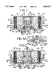
- FIG. 1 is a diametrical cross-sectional view of a new and improved air bag inflator and housing constructed in accordance with the features of the present invention
- FIG. 2 is a diametrical cross-sectional view of another embodiment of a new and improved air bag inflator and housing constructed in accordance with the features of the present invention
- FIG. 3 is a diametrical cross-sectional view of yet another embodiment of a new and improved air bag inflator and housing constructed in accordance with the features of the present invention
- FIG. 3A is a fragmentary portion of a diametrical cross-sectional view of the air bag inflator and housing of FIG. 3 employing a modified adapter and means of securing the adapter in place in accordance with the present invention
- FIG. 4 is a diametrical cross-sectional view of still another embodiment of a new and improved air bag inflator and housing constructed in accordance with the features of the present invention.
- Inflator 100 includes a housing or canister 102 formed of metal such as aluminum or steel sheet or plate material having an upper, inverted cup-shaped diffuser cover 104 and a generally circular, annular base 106 having a central opening 107 formed thereon and joined to form a sealed enclosure or housing for containing a quantity of solid, gas generant material 108 in the form of pellets or wafers which rapidly combust to provide a necessary volume of inflation gas for deployment of an air bag in communication with the inflator 100.
- a housing or canister 102 formed of metal such as aluminum or steel sheet or plate material having an upper, inverted cup-shaped diffuser cover 104 and a generally circular, annular base 106 having a central opening 107 formed thereon and joined to form a sealed enclosure or housing for containing a quantity of solid, gas generant material 108 in the form of pellets or wafers which rapidly combust to provide a necessary volume of inflation gas for deployment of an air bag in communication with the inflator 100.
- the diffuser cover 104 includes a circular top wall 110 and an integral, downwardly depending, cylindrical outer side wall 112 having a radially outwardly extending mounting flange 114 secured thereto for mounting of the inflator 100 in a steering wheel hub assembly of a motor vehicle.
- the cylindrical outer wall 112 and the circular top wall 110 may be formed of sheet aluminum or steel in a spin-forming or deep draw operation, and the outer side wall 112 is provided with a plurality of gas discharge ports 116 arranged around the periphery for directing the gas generated in the housing 102 outwardly into an air bag (not shown) as indicated by the radially extending arrows A.
- the inflator 100 also includes a centrally disposed, cylindrical inner side wall 120 in coaxial alignment with the outer side wall 112.
- the inner side wall 120 has an upper end joined to the interior surface of the top wall 110 by an annular weld 122 which may be formed in a spin type inertia welding operation or other joining method.
- the inner side wall 120 forms a centrally disposed, ignition chamber 124 for containing an ignition squib 126 and a charge 128 of an ignition-enhancing material contained within an igniter cup 129 positioned in the upper end portion of the chamber.
- the ignition squib 126 is electrically activated and includes a pair of electrical terminals 126a for connection to an electrical activation system of a motor vehicle.
- the inner side wall 120 is formed with a plurality of ignition ports 130 in direct communication between the ignition chamber 124 and an outer, surrounding, annular, combination combustion and filter-containing chamber 132.
- the gas generant material 108 is arranged in an annular mass and is encircled by an annular filter 134 mounted adjacent the inside surface of the outer side wall 112.
- the ignition chamber wall ports 130 direct hot combustion products from the ignition squib 126 and the ignition enhancing material 128 into the annulus of gas generant pellets 108 as indicated by the arrows B.
- annular filters 134 may be utilized; and in general, the filter includes a large area, cylindrically-shaped, inner face for receiving hot combustion products generated in the housing 102 and an outer surface in facing confrontation with the diffuser discharge ports 116.
- the diffuser ports 116 are sealed off against the entry of outside contaminants during the life of the inflator 100 before activation by means of an adhesive aluminum foil sealing tape 136, which is readily ruptured by gas pressure when activation of the inflator 100 to fill an associated air bag takes place.
- Upper and lower annular end surfaces of the filter 134 are sealed against the underside of the top wall 110 and the upper surface of the base wall 106, respectively, by a pair of resilient, annular, sealing ring gaskets 138 and 140 in order to prevent blow-by of the hot gases around the upper and lower ends of the filter 134.
- the sealing rings 138 and 140 ensure good filtering action by containing the gas flow within the available flow cross-section of the filter 134 until reaching the diffuser wall ports 116.
- a lower end portion 120a of the cylindrical inner side wall 120 is adapted to be crimp-formed over against an adjacent inner edge portion 106a around a central opening 107 in the annular circular base 106 during final assembly of the inflator.
- a lower end portion 112a of the outer cylindrical side wall 112 is designed to be crimped over to establish a crimp-formed joint against an outer peripheral edge portion 106b of the circular base wall 106 to complete the sealing or closing of the canister 102 after all of the internal components have been inserted. Crimping of the outer side wall 112a against the base wall edge portion 106b applies compression against the ring seals 138 and 140 on upper and lower end faces of the filter 134 to provide positive sealing against gas blow-by.
- An adapter plug 142 formed of metal holds and supports electrically activated ignition squib 126 and the plug is seated in place to close the lower end of the ignition chamber 124.
- the squib 126 is secured to the adapter 142 by crimping an open upper end portion 142a over against the upper surface of the squib 126 as shown by the arrows C and in solid lines in FIG. 1.
- the adapter body 142 includes an outwardly extending, radially disposed lower end flange 142b which abuts the crimped-over, lower end segment 120a of the inner side wall 120 when the adapter is inserted into place in the lower end portion of the central ignition chamber 124.
- the adapter 142 is provided with a washer-like mounting plate 144 at the lower end which is secured to the base wall 106 by an annular weld 146 to complete the final assembly of the enclosure or diffuser housing 102.
- a hermetic, resilient, sealing ring or gasket 148 of elastomeric material is disposed between an outer portion of the adapter flange 142b, and confronting the portions of the crimped-over lower end portion 120a of the inner side wall 120 and a surface portion of the base plate 106.
- the use of forming procedures in crimping over the lower end portion 120a of the inner side wall 120 against the edge portion 106a around the central opening 107 of the base wall 106 and the crimping over of the lower end portion 112a of the cylindrical outer side wall 112 against the outer edge peripheral portion 106b of the base 106 greatly facilitates the rapid assembly of the air bag inflator 100 and allows the use of relatively lower cost sheet material of aluminum or steel instead of more expensive cast or forged structures.
- the crimp-forming operations used in joining the inner and outer side walls 120 and 112, respectively, to the base wall 106 provides positive compression on the blow-by seals 138 and 140 acting on the filter 134.
- Inflator 200 includes a housing or canister 202 formed of metal such as aluminum or steel sheet or plate material having an upper, inverted cup-shaped diffuser cover 204 and a generally circular, annular base 206 having a central opening 207 and joined to form a sealed enclosure or housing for containing a quantity of solid, gas generant material 208 in the form of pellets or wafers, which rapidly combust to provide a necessary volume of inflation gas for deployment of an air bag in communication with the inflator 200.
- a housing or canister 202 formed of metal such as aluminum or steel sheet or plate material having an upper, inverted cup-shaped diffuser cover 204 and a generally circular, annular base 206 having a central opening 207 and joined to form a sealed enclosure or housing for containing a quantity of solid, gas generant material 208 in the form of pellets or wafers, which rapidly combust to provide a necessary volume of inflation gas for deployment of an air bag in communication with the inflator 200.
- the diffuser cover 204 includes a circular top wall 210 and an integral, downwardly depending, cylindrical outer side wall 212 having a radially outwardly extending mounting flange 214 secured thereto for mounting of the inflator 200 in a steering wheel hub assembly of a motor vehicle.
- the cylindrical outer side wall 212 and the circular top wall 210 may be formed by forging.
- the outer side wall 212 is provided with a plurality of gas discharge ports 216 for directing the gas generated in the housing 202 outwardly into an air bag (not shown) as indicated by the radially extending arrows A.
- the inflator 200 also includes a centrally disposed, integrally formed cylindrical inner side wall 220 in coaxial alignment with the outer side wall 212.
- the inner side wall 220 has an upper end integrally forged to join the interior surface of the top wall 210.
- the inner side wall 220 forms a centrally disposed, cylindrically-shaped ignition chamber 224 for containing an ignition squib 226 and a charge 228 of an ignition-enhancing material contained within a cup 229 mounted in the upper end portion of the chamber and held in place by a spring washer 231.
- the ignition squib 226 is electrically activated and includes a pair of dependent electrical terminals 226a for connection to an electrical activation system of a motor vehicle.
- the inner side wall 220 is formed with a plurality of ignition ports 230 in direct communication between the ignition chamber 224 and an outer, surrounding, annular, combination combustion and filter-containing chamber 232.
- the gas generant material 208 is arranged in an annular mass and is encircled by an annular filter 234 mounted adjacent the inside surface of the outer side wall 212.
- the ignition chamber wall ports 230 direct hot combustion products from the ignition squib 226 and the ignition enhancing material 228 into the gas generant pellets 208 as indicated by the arrows B.
- annular filters 234 may be utilized; and in general, the filter includes a large area, cylindrically-shaped, inner face for receiving hot combustion products generated in the housing 202 and an outer surface in facing confrontation with the diffuser discharge ports 216.
- the diffuser ports 216 are sealed off against the entry of outside contaminants during the life of the inflator 200 before activation by means of an adhesive aluminum foil sealing tape 236, which is readily ruptured by gas pressure when activation of the inflator 200 to fill an associated air bag takes place.
- Upper and lower annular end surfaces of the filter 234 are sealed against the underside of the top wall 210 and the upper surface of the base wall 206, respectively, by a pair of resilient, annular, sealing ring gaskets 238 and 240 in order to prevent blow-by of the hot gases around the upper and lower ends of the filter 234.
- the sealing rings 238 and 240 ensure good filtering action by containing the gas flow within the available flow cross-section of the filter 234 until reaching the diffuser wall ports 216.
- a lower end portion 220a of the cylindrical inner side wall 220 is crimp-formed over and against an adjacent inner edge portion 206a around a central opening 207 in the annular circular base 206.
- the joint is established in a crimp-forming operation.
- a lower end portion 212a of the outer cylindrical side wall 212 is designed to be crimped over to establish a crimp-formed joint against an outer peripheral edge portion 206b of the circular base wall 206 to complete the sealing or closing of the canister 202 after all of the internal components have been inserted. Crimping of the outer side wall 212a against the base wall edge portion 206b applies compression against the ring seals 238 and 240 on upper and lower end faces of the filter 234 to provide positive sealing against gas blow-by.
- An adapter plug 242 formed of metal holds and supports an electrically activated ignition squib 226 and the plug is seated in place to close the lower end of the ignition chamber 224.
- the squib 226 may be integrally molded into place in the adapter plug 242 with the electrical terminals 226a extending downwardly.
- the adapter plug 242 includes an outwardly extending, radially disposed, lower end flange 242b which abuts the crimped-over, lower end segment 220a of the inner side wall 220 when the adapter is inserted into place in the lower end portion of the central ignition chamber 224.
- the adapter 242 is provided with a washer-like mounting plate 244 at the lower end which is secured to the base wall 206 by an annular weld 246 to complete the assembly of the enclosure or diffuser housing 202.
- a hermetic, resilient, sealing ring or gasket 248 of elastomeric material is disposed between an outer portion of the adapter flange 242b, and confronting the portions of the crimped-over lower end portion 220a of the inner side wall 220 and an outer surface portion of the base plate 206.
- a thin holding cover 249 of annular shape may be inserted between the lower ring seal 240 and the inner side wall 220.
- the use of forming procedures in crimping over the lower end portion 220a of the inner side wall 220 against the edge portion 206a around the central opening 207 of the base wall 206 and the crimping over of the lower end portion 212a of the cylindrical outer side wall 212 against the outer edge peripheral portion 206b of the base 206 greatly facilitates the rapid assembly of the air bag inflator 200 and allows the use of relatively lower cost sheet material of aluminum or steel for the base 206.
- the crimp-forming operations used in joining the inner and outer side walls 220 and 212, respectively, to the base wall 206 provides positive compression on the blow-by seals 238 and 240 at opposite end faces of the filter 234.
- Inflator 300 includes a housing or canister 302 formed of sheet metal such as aluminum or steel having an upper, inverted cup-shaped diffuser cover 304 and a generally circular, annular base 306 joined to form a sealed enclosure or housing for containing a quantity of solid, gas generant material 308 in the form of pellets or wafers.
- the gas generant material 308 is adapted to rapidly combust to provide a necessary volume of inflation gas for deployment of an air bag in communication with the inflator 300.
- the diffuser cover 304 includes a circular top wall 310 having a central aperture 311 therein.
- An integral, downwardly depending, cylindrical outer side wall 312 joins the outer peripheral edge of the top wall.
- a radially outwardly extending mounting flange 314 is secured to the outer side wall 312 for mounting of the inflator 300 in a steering wheel hub assembly (not shown) of a motor vehicle.
- the cylindrical outer side wall 312 and the circular top wall 310 may be formed of sheet aluminum or steel in a spin-forming or deep draw operation, and the outer side wall 312 is provided with a plurality of gas discharge ports 316 for directing the gas generated in the housing 302 outwardly into an air bag (not shown) as indicated by the radially extending arrows A.
- the inflator 300 includes a cylindrical ignition chamber 324 which is formed by a rivet-like forged member 325 having a circular top wall 327 with an outer edge portion 327a facing a circular edge portion 311a on the upper surface of the top wall 310 around the central opening 311.
- An annular sealing gasket 329 is placed between the edge portions 327a and 311a to provide an airtight hermetic seal.
- an outer edge of the top wall 327 may be welded to the depressed circular edge portion 311a of the top wall 310 with an annular weld 333 forming a hermetic seal.
- annular weld 335 (dotted lines) such as a laser weld or shot weld may be provided between the edge portions 311a and 327a to provide a hermetic seal in lieu of the gasket 329.
- the member 325 includes an integral, inner side wall 320 in coaxial alignment with the outer side wall 312 extending downwardly from the underside of the top wall 327.
- the ignition chamber 324 contains an ignition squib integrally molded in an adapter 342 at the lower end portion and a charge of an ignition-enhancing material 328 contained within an igniter cup 349 positioned in an upper end portion and secured in place after insertion by an upset ring 331 formed on the inside wall surface of the inner side wall 320.
- the ignition squib is electrically activated and includes a pair of dependent electrical terminals 326a for connection to an electrical activation system of a motor vehicle.
- the inner side wall 320 is formed with a plurality of ignition ports 330 in direct communication between the ignition chamber 324 and an outer, surrounding, annular, combination combustion and filter-containing chamber 332.
- the gas generant material 308 is arranged in an annular mass and is encircled by an annular filter 334 mounted adjacent the inside surface of the outer side wall 312.
- the ignition chamber wall ports 330 direct hot combustion products from the ignition squib 326 and the ignition enhancing material 328 into the annulus of gas generant pellets 308 as indicated by the arrows B when the inflator 300 is activated.
- annular filters 334 may be utilized.
- the filter includes a large-sized area of cylindrical shape forming an inlet side or inner face for receiving hot combustion products generated in the housing 302.
- a cylindrical outer face of the filter 334 is positioned in facing confrontation with the diffuser discharge ports 316.
- the diffuser ports 316 are sealed off against the entry of outside contaminants during the life of the inflator 300 before activation by means of an adhesive aluminum or metallized foil sealing tape 336, which is readily ruptured by gas pressure when activation of the inflator 300 takes place.
- Upper and lower annular end surfaces of the filter 334 are sealed against the underside of the top wall 310 and the upper surface of the base wall 306, respectively, by a pair of resilient, annular, sealing ring gaskets 338 and 340 in order to prevent blow-by of the hot gases around the upper and lower ends of the filter 334.
- the sealing rings 338 and 340 ensure good filtering action by containing the gas flow within the available flow cross-section of the filter 334 until reaching the diffuser wall ports 316.
- a lower end portion 320a of the cylindrical inner side wall 320 is adapted to be crimp-formed over against an adjacent inner edge portion 306a around a central opening 307 in the annular circular base 306.
- the central openings 311 and 307 in the respective top wall 310 and base 306 are in coaxial alignment and equal in diameter to accommodate the inner side wall 320 of the forged member 325 which extends through the openings.
- a sealing gasket 339 may be provided between the crimped-over lower end portion 320a of the inner side wall 320 and the edge portion 306a of the base wall 306 around the central opening 307.
- annular welds like the welds 333 and 335 may be utilized to provide a hermetic seal between the edge portions 306a and 320a.
- the joint between the edge portions 306a and 320a is established in a crimp-forming operation.
- a flanged plug 342 containing the electrically activated ignition squib is seated in place to close the lower end of the ignition chamber 324 during final assembly.
- the plug 342 is secured in place by a crimp-forming operation to provide an inwardly directed upset ring 320b which bears against a shoulder 342a on the plug.
- the adapter plug 342 is provided with a seal ring 343 which bears against the inner side wall 320 when the squib containing adapter 342 is inserted into place in the lower end portion of the central ignition chamber 324 to provide a hermetic seal.
- an air bag inflator 300 which includes a modified adapter plug 342 having no seal ring 343 and secured in position by an annular weld 321 which provides a hermetic seal rather than by a radially inwardly directed crimped-over lower edge portion 320b as shown in FIG. 3.
- the outer side wall 312 is formed with an outwardly extending radial flange 312a which abuts against an outer edge portion 306b of the base 306.
- the abutting surfaces are held together to hermetically seal the housing 302, by means of a channel-like, roll-formed inner edge portion 314a of the mounting bracket 314.
- a seal 350 or a weld may be utilized to ensure a hermetic seal between the outer side wall 312 and the base wall 306.
- the use of forming procedures in crimping over the lower end portion 320a of the inner side wall 320 against the edge portion 306a around the central opening 307 of the base wall 306 and the upset or crimping over of the inside end portion 320b against the adapter plug 342 facilitates the rapid assembly of the air bag inflator 300 and allows the use of relatively lower cost sheet material of aluminum or steel to be used instead of more expensive cast or forged structures.
- the adapter plug 342 may be welded into rivet-like member 325 eliminating need for crimped over inside end portion 320b and seal ring 343.
- the strong rivet-like forged member 325 provides an excellent way of securing central portions of the top wall 310 and base wall 306 against bulging or fracture from gas pressure when the inflator 300 is activated.
- the inflator 400 includes a housing or canister 402 formed of sheet metal such as aluminum or steel and hollow tubular elements of similar material.
- the housing 402 includes an annular, generally circular, washer-like top wall 410 having a central opening 411 and a parallel, similarly dimensioned annular base 406.
- end walls 406 and 410 are joined together by concentric, tubular inner and outer side walls 420 and 412, respectively, to form a sealed enclosure or housing for containing a quantity of solid, gas generant material 408 in the form of pellets or wafers, which rapidly combust to provide a necessary volume of inflation gas for deployment of an air bag in communication with the inflator 400.
- the outer side wall 412 is provided with a plurality of gas discharge ports 416 around the periphery for directing the gas generated in the housing 402 outwardly into an air bag (not shown) as indicated by the outwardly extending arrows A.
- the tubular inner side wall 420 has an upper end portion 420a' which is crimp-formed outwardly to face an edge portion 410a on the outer surface of the top wall 410 around the central opening 411.
- a sealing ring or gasket 429 may be provided between the portions 410a and 420a' to ensure a hermetic seal.
- the inner side wall 420 forms a centrally disposed, ignition chamber 424 for containing an integrally molded-in-place ignition squib 426 which is electrically activated and including a pair of dependent electrical terminals 426a for connection to an electrical activation system of a motor vehicle.
- the upper end of the ignition chamber 424 is closed by an integrally formed end wall 425 which forms the base of an inverted cup for containing and supporting the squib 426.
- the tubular inner side wall 420 is formed with a plurality of ignition ports 430 in direct communication with an outer, surrounding, annular, combination combustion and filter-containing chamber 432.
- the gas generant material 408 is arranged in an annular mass and is encircled by an annular filter 434 mounted adjacent the inside surface of the tubular outer side wall 412.
- the ignition chamber wall ports 430 are designed to direct hot combustion products from the ignition squib 426 into the annulus of gas generant pellets 408 as indicated by the arrows B.
- annular filters 434 may be utilized; and in general, the filter includes a large size inlet area of cylindrical shape as an inner face for receiving hot combustion products generated in the housing 402.
- the filter includes a cylindrical outer surface in facing confrontation with the diffuser discharge ports 416.
- the ports 416 are sealed off against the entry of outside contaminants during the inactive life of the inflator 400 before activation by means of an adhesive aluminum foil sealing tape 436, which is readily ruptured by gas pressure when activation of the inflator 400 takes place.
- Upper and lower annular end surfaces of the filter 434 are sealed against the underside of the top wall 410 and the upper surface of the base wall 406, respectively, by a pair of resilient, annular, sealing ring gaskets 438 and 440 in order to prevent blow-by of the hot gases around the upper and lower ends of the filter 434.
- the sealing rings 438 and 440 ensure good filtering action by containing the gas flow within the available flow cross-section of the filter 434 until reaching the diffuser wall ports 416.
- a lower end portion 420a of the tubular inner side wall 420 is crimp-formed over and against an adjacent inner edge portion 406a around a central opening 407 provided in the annular circular base 406.
- the joints between the portions 406a and 420a are established in a crimp-forming operation.
- Upper and lower end portions 412a' and 412a of the outer tubular side wall 412 are designed to be crimped over to establish crimp-formed joints against outer peripheral edge portions 410b and 406b of the annular circular top wall 410 and the base wall 406 to complete the sealing or closing of the canister 402 after all of the internal components have been inserted.
- Crimping of the tubular outer side wall portions 412a and 412a' against the top wall edge portion 410b and base wall edge portion 406b applies compression against the ring seals 438 and 440 on upper and lower end surfaces of the filter 434 to provide positive sealing against gas blow-by and form hermetic seals between the top and bottom end walls 410 and 406 and the tubular outer side wall 412.
- An ignitor containing the molded-in-place, electrically activated ignition squib 426 is seated in the ignition chamber 424 and held in place by an upset-formed ring 455 on the inside surface of the tubular inner side wall 420.
Abstract
Description
Claims (51)
Priority Applications (3)
| Application Number | Priority Date | Filing Date | Title |
|---|---|---|---|
| US08/330,344 US5458371A (en) | 1994-10-27 | 1994-10-27 | Crimp-formed joint housings for air bag inflators |
| JP1995010985U JP3023843U (en) | 1994-10-27 | 1995-10-17 | Airbag inflator housing |
| EP95307673A EP0709263A1 (en) | 1994-10-27 | 1995-10-27 | Crimp-formed joint housings for air bag inflators |
Applications Claiming Priority (1)
| Application Number | Priority Date | Filing Date | Title |
|---|---|---|---|
| US08/330,344 US5458371A (en) | 1994-10-27 | 1994-10-27 | Crimp-formed joint housings for air bag inflators |
Publications (1)
| Publication Number | Publication Date |
|---|---|
| US5458371A true US5458371A (en) | 1995-10-17 |
Family
ID=23289349
Family Applications (1)
| Application Number | Title | Priority Date | Filing Date |
|---|---|---|---|
| US08/330,344 Expired - Lifetime US5458371A (en) | 1994-10-27 | 1994-10-27 | Crimp-formed joint housings for air bag inflators |
Country Status (3)
| Country | Link |
|---|---|
| US (1) | US5458371A (en) |
| EP (1) | EP0709263A1 (en) |
| JP (1) | JP3023843U (en) |
Cited By (22)
| Publication number | Priority date | Publication date | Assignee | Title |
|---|---|---|---|---|
| US5613706A (en) * | 1995-12-13 | 1997-03-25 | Morton International, Inc. | Self-contained inflator pyrotechnic initiator |
| EP0800964A2 (en) * | 1996-04-08 | 1997-10-15 | Daicel Chemical Industries, Ltd. | An airbag inflator and an airbag apparatus |
| US5746618A (en) * | 1995-07-14 | 1998-05-05 | Augat Inc. | Squib connector for automotive air bag assembly |
| EP0857627A1 (en) * | 1997-02-10 | 1998-08-12 | Daicel Chemical Industries, Ltd. | Gas generator for an air bag and air bag system |
| EP0896912A1 (en) * | 1997-08-12 | 1999-02-17 | Daicel Chemical Industries, Ltd. | Gas generator for air bag and air bag system |
| US5882224A (en) * | 1996-08-28 | 1999-03-16 | Thomas & Betts International, Inc. | Squib connector socker assembly having shorting clip for automotive air bags |
| US5895282A (en) * | 1996-05-24 | 1999-04-20 | Thomas & Betts Corporation | Connector for airbag gas generator |
| US5908481A (en) * | 1997-02-06 | 1999-06-01 | Automotive Systems Laboratory, Inc. | Inflator filter comprising carbon yarn |
| US5993230A (en) * | 1996-08-12 | 1999-11-30 | Thomas & Betts International, Inc. | Orientationless squib connector assembly for automotive air bag assemblies |
| US6213501B1 (en) * | 1998-03-19 | 2001-04-10 | Autoliv Asp, Inc. | Method of improving ballistics by ignition system porting in an airbag inflator |
| US6276953B1 (en) | 1997-12-04 | 2001-08-21 | Thoma & Betts International, Inc. | Orientationless squib connector assembly for automotive air bag assemblies |
| US6283505B1 (en) * | 1996-11-14 | 2001-09-04 | Nippon Kayaku Kabushiki-Kaisha | Gas generator for air bag |
| US20030218317A1 (en) * | 2002-03-27 | 2003-11-27 | Takeshi Yamazaki | Airbag apparatus |
| US20040041382A1 (en) * | 2002-03-19 | 2004-03-04 | Yuzo Gotoh | Inflator with a cap |
| US20090115175A1 (en) * | 2005-09-15 | 2009-05-07 | Nipppon Kayaku Kabushiki Kaisha, | Gas generator |
| WO2010082680A1 (en) | 2009-01-15 | 2010-07-22 | Daicel Chemical Industries, Ltd. | Gas generator for restraining device of vehicle |
| WO2010082679A1 (en) * | 2009-01-15 | 2010-07-22 | Daicel Chemical Industries, Ltd. | Gas generator for restraining device of vehicle |
| US20120174815A1 (en) * | 2011-01-06 | 2012-07-12 | Shinichiro Ukita | Gas generator |
| US8424908B2 (en) | 2009-01-15 | 2013-04-23 | Daicel Chemical Industries, Ltd. | Gas generator for restraining device of vehicle |
| WO2013161431A1 (en) | 2012-04-23 | 2013-10-31 | Daicel Corporation | Gas generator |
| WO2013161430A1 (en) | 2012-04-25 | 2013-10-31 | Daicel Corporation | Gas generator |
| US8720944B2 (en) | 2009-01-15 | 2014-05-13 | Daicel Chemical Industries, Ltd. | Gas generator for restraining device of vehicle |
Families Citing this family (1)
| Publication number | Priority date | Publication date | Assignee | Title |
|---|---|---|---|---|
| JP2015202825A (en) * | 2014-04-16 | 2015-11-16 | 株式会社ダイセル | gas generator |
Citations (20)
| Publication number | Priority date | Publication date | Assignee | Title |
|---|---|---|---|---|
| DE2443267A1 (en) * | 1973-09-14 | 1975-03-20 | Eaton Corp | SAFETY DEVICE FOR MOTOR VEHICLE OCCUPANTS |
| US3958949A (en) * | 1973-06-26 | 1976-05-25 | Societe Nationale Des Poudres Et Explosifs | Gas generator with a combustion chamber laterally surrounded by a cooling chamber |
| US3985076A (en) * | 1973-11-19 | 1976-10-12 | Thiokol Corporation | Gas generator |
| US4116466A (en) * | 1974-11-29 | 1978-09-26 | Eaton Corporation | Fluid supply for occupant restraint system |
| US4131299A (en) * | 1976-04-05 | 1978-12-26 | Daicel Ltd. | Gas generator for inflatable vehicle collision bag |
| US4370930A (en) * | 1980-12-29 | 1983-02-01 | Ford Motor Company | End cap for a propellant container |
| US4394033A (en) * | 1981-02-26 | 1983-07-19 | The Firestone Tire & Rubber Company | Temperature compensating elastic cone |
| US4530516A (en) * | 1984-07-09 | 1985-07-23 | Morton Thiokol Inc. | Aluminum inflator with steel center-tie |
| US4547342A (en) * | 1984-04-02 | 1985-10-15 | Morton Thiokol, Inc. | Light weight welded aluminum inflator |
| US4561675A (en) * | 1984-04-02 | 1985-12-31 | Morton Thiokol, Inc. | Auto ignition device |
| US4734265A (en) * | 1984-07-13 | 1988-03-29 | Bayern Chemie Gesellschaft fur Flugchemische Antrieb mit beschrankter Haftung | Gas generator for safety belt tightening equipment of a vehicle |
| US5000479A (en) * | 1988-09-21 | 1991-03-19 | Bayern-Chemie Gesellschaft Fuer Flugchemische Antriebe Mbh | Housing for a gas generator |
| JPH03186453A (en) * | 1989-12-14 | 1991-08-14 | Nippon Oil & Fats Co Ltd | Gas generator |
| US5139280A (en) * | 1989-07-05 | 1992-08-18 | S.N.C. Livbag | Cold-gas pyrotechnic generator |
| US5221107A (en) * | 1990-12-18 | 1993-06-22 | Trw Inc. | Prefilter assembly |
| US5260038A (en) * | 1992-04-08 | 1993-11-09 | Daicel Chemical Industries, Ltd. | Gas generator for air bags with circumferentially disposed blades |
| US5275431A (en) * | 1991-09-18 | 1994-01-04 | Trw Inc. | Air bag inflator assembly |
| US5306041A (en) * | 1991-06-21 | 1994-04-26 | Daicel Chemical Industries, Ltd. | Gas generator having housing of double structure |
| US5340150A (en) * | 1990-07-16 | 1994-08-23 | Asahi Kasei Kogyo Kabushiki Kaisha | Inflator for air bag |
| US5382415A (en) * | 1993-06-22 | 1995-01-17 | Nippon Koki Co., Ltd. | Air bag inflation gas generator |
Family Cites Families (4)
| Publication number | Priority date | Publication date | Assignee | Title |
|---|---|---|---|---|
| DE2824701C2 (en) * | 1978-06-06 | 1982-11-11 | Bayern-Chemie Gesellschaft für flugchemische Antriebe mbH, 8261 Aschau | Gas generator |
| US4923212A (en) * | 1988-08-17 | 1990-05-08 | Talley Automotive Products, Inc. | Lightweight non-welded inflator unit for automobile airbags |
| US4907819A (en) * | 1988-09-16 | 1990-03-13 | Talley Automotive Products, Inc. | Lightweight non-welded gas generator with rolled spun lip |
| US5398967A (en) * | 1993-08-18 | 1995-03-21 | Precision Engineering Co. | Air bag inflator |
-
1994
- 1994-10-27 US US08/330,344 patent/US5458371A/en not_active Expired - Lifetime
-
1995
- 1995-10-17 JP JP1995010985U patent/JP3023843U/en not_active Expired - Lifetime
- 1995-10-27 EP EP95307673A patent/EP0709263A1/en not_active Withdrawn
Patent Citations (20)
| Publication number | Priority date | Publication date | Assignee | Title |
|---|---|---|---|---|
| US3958949A (en) * | 1973-06-26 | 1976-05-25 | Societe Nationale Des Poudres Et Explosifs | Gas generator with a combustion chamber laterally surrounded by a cooling chamber |
| DE2443267A1 (en) * | 1973-09-14 | 1975-03-20 | Eaton Corp | SAFETY DEVICE FOR MOTOR VEHICLE OCCUPANTS |
| US3985076A (en) * | 1973-11-19 | 1976-10-12 | Thiokol Corporation | Gas generator |
| US4116466A (en) * | 1974-11-29 | 1978-09-26 | Eaton Corporation | Fluid supply for occupant restraint system |
| US4131299A (en) * | 1976-04-05 | 1978-12-26 | Daicel Ltd. | Gas generator for inflatable vehicle collision bag |
| US4370930A (en) * | 1980-12-29 | 1983-02-01 | Ford Motor Company | End cap for a propellant container |
| US4394033A (en) * | 1981-02-26 | 1983-07-19 | The Firestone Tire & Rubber Company | Temperature compensating elastic cone |
| US4547342A (en) * | 1984-04-02 | 1985-10-15 | Morton Thiokol, Inc. | Light weight welded aluminum inflator |
| US4561675A (en) * | 1984-04-02 | 1985-12-31 | Morton Thiokol, Inc. | Auto ignition device |
| US4530516A (en) * | 1984-07-09 | 1985-07-23 | Morton Thiokol Inc. | Aluminum inflator with steel center-tie |
| US4734265A (en) * | 1984-07-13 | 1988-03-29 | Bayern Chemie Gesellschaft fur Flugchemische Antrieb mit beschrankter Haftung | Gas generator for safety belt tightening equipment of a vehicle |
| US5000479A (en) * | 1988-09-21 | 1991-03-19 | Bayern-Chemie Gesellschaft Fuer Flugchemische Antriebe Mbh | Housing for a gas generator |
| US5139280A (en) * | 1989-07-05 | 1992-08-18 | S.N.C. Livbag | Cold-gas pyrotechnic generator |
| JPH03186453A (en) * | 1989-12-14 | 1991-08-14 | Nippon Oil & Fats Co Ltd | Gas generator |
| US5340150A (en) * | 1990-07-16 | 1994-08-23 | Asahi Kasei Kogyo Kabushiki Kaisha | Inflator for air bag |
| US5221107A (en) * | 1990-12-18 | 1993-06-22 | Trw Inc. | Prefilter assembly |
| US5306041A (en) * | 1991-06-21 | 1994-04-26 | Daicel Chemical Industries, Ltd. | Gas generator having housing of double structure |
| US5275431A (en) * | 1991-09-18 | 1994-01-04 | Trw Inc. | Air bag inflator assembly |
| US5260038A (en) * | 1992-04-08 | 1993-11-09 | Daicel Chemical Industries, Ltd. | Gas generator for air bags with circumferentially disposed blades |
| US5382415A (en) * | 1993-06-22 | 1995-01-17 | Nippon Koki Co., Ltd. | Air bag inflation gas generator |
Cited By (47)
| Publication number | Priority date | Publication date | Assignee | Title |
|---|---|---|---|---|
| US5746618A (en) * | 1995-07-14 | 1998-05-05 | Augat Inc. | Squib connector for automotive air bag assembly |
| US5613706A (en) * | 1995-12-13 | 1997-03-25 | Morton International, Inc. | Self-contained inflator pyrotechnic initiator |
| US6234521B1 (en) | 1996-04-08 | 2001-05-22 | Daicel Chemical Industries, Ltd. | Airbag inflator and an airbag apparatus |
| EP0800964A2 (en) * | 1996-04-08 | 1997-10-15 | Daicel Chemical Industries, Ltd. | An airbag inflator and an airbag apparatus |
| EP0800964A3 (en) * | 1996-04-08 | 1997-12-17 | Daicel Chemical Industries, Ltd. | An airbag inflator and an airbag apparatus |
| CN1101321C (en) * | 1996-04-08 | 2003-02-12 | 大赛璐化学工业株式会社 | Air sac inflator and air sac device |
| US6409214B2 (en) * | 1996-04-08 | 2002-06-25 | Daicel Chemical Industries, Ltd. | Airbag inflator and an airbag apparatus |
| US6196581B1 (en) | 1996-04-08 | 2001-03-06 | Daicel Chemical Industries, Ltd. | Airbag inflator and an airbag apparatus |
| EP1074437A3 (en) * | 1996-04-08 | 2001-04-04 | Daicel Chemical Industries, Ltd. | An airbag inflator |
| EP1074437A2 (en) * | 1996-04-08 | 2001-02-07 | Daicel Chemical Industries, Ltd. | An airbag inflator |
| US5895282A (en) * | 1996-05-24 | 1999-04-20 | Thomas & Betts Corporation | Connector for airbag gas generator |
| US5993230A (en) * | 1996-08-12 | 1999-11-30 | Thomas & Betts International, Inc. | Orientationless squib connector assembly for automotive air bag assemblies |
| US6203342B1 (en) | 1996-08-12 | 2001-03-20 | Thomas & Betts International, Inc. | Grounding plate for orientationless squib connector assembly for automotive air bag assemblies |
| US6145193A (en) * | 1996-08-28 | 2000-11-14 | Thomas & Betts International, Inc. | Method of forming a squib connector socket assembly having shorting clip for automotive air bags |
| US5882224A (en) * | 1996-08-28 | 1999-03-16 | Thomas & Betts International, Inc. | Squib connector socker assembly having shorting clip for automotive air bags |
| US6283505B1 (en) * | 1996-11-14 | 2001-09-04 | Nippon Kayaku Kabushiki-Kaisha | Gas generator for air bag |
| US5908481A (en) * | 1997-02-06 | 1999-06-01 | Automotive Systems Laboratory, Inc. | Inflator filter comprising carbon yarn |
| US6324760B1 (en) | 1997-02-10 | 2001-12-04 | Daicel Chemical Industries, Ltd. | Method of making gas generator for air bag |
| US6170869B1 (en) | 1997-02-10 | 2001-01-09 | Daicel Chemical Industries, Ltd. | Gas generator for air bag and air bag system |
| EP0857627A1 (en) * | 1997-02-10 | 1998-08-12 | Daicel Chemical Industries, Ltd. | Gas generator for an air bag and air bag system |
| CN1093054C (en) * | 1997-02-10 | 2002-10-23 | 大赛璐化学工业株式会社 | Air generator for safety air bag and safety air bag unit |
| EP0896912A1 (en) * | 1997-08-12 | 1999-02-17 | Daicel Chemical Industries, Ltd. | Gas generator for air bag and air bag system |
| US6129381A (en) * | 1997-08-12 | 2000-10-10 | Daicel Chemical Industries, Ltd. | Gas Generator for air bag and air bag system |
| US6334245B2 (en) * | 1997-08-12 | 2002-01-01 | Daicel Chemical Industries, Ltd. | Method of making gas generator for air bag and air bag system |
| US6231080B1 (en) | 1997-08-12 | 2001-05-15 | Daicel Chemical Industries, Ltd. | Gas generator for air bag and air bag system |
| US6276953B1 (en) | 1997-12-04 | 2001-08-21 | Thoma & Betts International, Inc. | Orientationless squib connector assembly for automotive air bag assemblies |
| US6213501B1 (en) * | 1998-03-19 | 2001-04-10 | Autoliv Asp, Inc. | Method of improving ballistics by ignition system porting in an airbag inflator |
| US20040041382A1 (en) * | 2002-03-19 | 2004-03-04 | Yuzo Gotoh | Inflator with a cap |
| US20030218317A1 (en) * | 2002-03-27 | 2003-11-27 | Takeshi Yamazaki | Airbag apparatus |
| US7029029B2 (en) * | 2002-03-27 | 2006-04-18 | Honda Giken Kogyo Kabushiki Kaisha | Airbag apparatus |
| US20090115175A1 (en) * | 2005-09-15 | 2009-05-07 | Nipppon Kayaku Kabushiki Kaisha, | Gas generator |
| WO2010082679A1 (en) * | 2009-01-15 | 2010-07-22 | Daicel Chemical Industries, Ltd. | Gas generator for restraining device of vehicle |
| US8720944B2 (en) | 2009-01-15 | 2014-05-13 | Daicel Chemical Industries, Ltd. | Gas generator for restraining device of vehicle |
| CN102123890A (en) * | 2009-01-15 | 2011-07-13 | 大赛璐化学工业株式会社 | Gas generator for restraining device of vehicle |
| US20110221175A1 (en) * | 2009-01-15 | 2011-09-15 | Daicel Chemical Industries, Ltd. | Gas generator for restraining device of vehicle |
| WO2010082680A1 (en) | 2009-01-15 | 2010-07-22 | Daicel Chemical Industries, Ltd. | Gas generator for restraining device of vehicle |
| US8424909B2 (en) | 2009-01-15 | 2013-04-23 | Daicel Chemical Industries, Ltd. | Gas generator for restraining device of vehicle |
| US8424908B2 (en) | 2009-01-15 | 2013-04-23 | Daicel Chemical Industries, Ltd. | Gas generator for restraining device of vehicle |
| US8434783B2 (en) | 2009-01-15 | 2013-05-07 | Daicel Chemical Industries, Ltd. | Gas generator for restraining device of vehicle |
| CN102123890B (en) * | 2009-01-15 | 2013-07-17 | 大赛璐化学工业株式会社 | Gas generator for restraining device of vehicle |
| US20120174815A1 (en) * | 2011-01-06 | 2012-07-12 | Shinichiro Ukita | Gas generator |
| US8567319B2 (en) * | 2011-01-06 | 2013-10-29 | Daicel Corporation | Gas generator |
| WO2013161431A1 (en) | 2012-04-23 | 2013-10-31 | Daicel Corporation | Gas generator |
| US8708368B2 (en) | 2012-04-23 | 2014-04-29 | Daicel Corporation | Gas generator |
| CN104245436A (en) * | 2012-04-23 | 2014-12-24 | 株式会社大赛璐 | Gas generator |
| WO2013161430A1 (en) | 2012-04-25 | 2013-10-31 | Daicel Corporation | Gas generator |
| US9353703B2 (en) | 2012-04-25 | 2016-05-31 | Daicel Corporation | Gas generator |
Also Published As
| Publication number | Publication date |
|---|---|
| JP3023843U (en) | 1996-04-30 |
| EP0709263A1 (en) | 1996-05-01 |
Similar Documents
| Publication | Publication Date | Title |
|---|---|---|
| US5458371A (en) | Crimp-formed joint housings for air bag inflators | |
| EP0709262B1 (en) | Air bag inflators having housings with crimp-formed joints | |
| US5489118A (en) | Air bag inflator | |
| JP3038714U (en) | Built-in charge detonator for inflators | |
| US5615912A (en) | Inflator for air bag | |
| US5273722A (en) | Gas generator | |
| US20070001439A1 (en) | Gas generator for air bag | |
| US5683106A (en) | Single side wall air bag inflator and method of making the same | |
| JPH02152510A (en) | Filter assembly of non-welding expansion device | |
| KR900003004A (en) | Inflator of car airbag | |
| JPH02169345A (en) | Light weight and non-weld expander | |
| US5733135A (en) | Air bag inflator assembly with shorting clip | |
| US7104569B2 (en) | Air bag module with pressure regulator | |
| US5308588A (en) | Hermetically sealed container for air bag inflator | |
| KR100361702B1 (en) | Hybrid Inflator | |
| US5658517A (en) | Method of forming an automotive air bag filter with support member | |
| US6068294A (en) | Vertical seat locking retainer disk and tube combination | |
| US5199741A (en) | Method of assembling an inflator | |
| US6705637B1 (en) | Inflator | |
| US5957492A (en) | Gas generator | |
| JPH09323614A (en) | Inflater for air bag | |
| US5203587A (en) | Method of assembly of a combustion cup, filter, and diffuser cup for a vehicle occupant restraint inflator | |
| JPH084367Y2 (en) | Gas generator for airbag deployment | |
| WO2000044594A1 (en) | Gas generator | |
| JPH10297415A (en) | Gas generator |
Legal Events
| Date | Code | Title | Description |
|---|---|---|---|
| AS | Assignment |
Owner name: MORTON INTERNATIONAL, INC., ILLINOIS Free format text: ASSIGNMENT OF ASSIGNORS INTEREST;ASSIGNORS:FULMER, BRIAN H.;PARKER, TODD S.;SMITH, BRADLEY W.;AND OTHERS;REEL/FRAME:007256/0688;SIGNING DATES FROM 19940930 TO 19941003 |
|
| STCF | Information on status: patent grant |
Free format text: PATENTED CASE |
|
| CC | Certificate of correction | ||
| AS | Assignment |
Owner name: AUTOLIV ASP, INC, UTAH Free format text: MERGER AND CHANGE OF NAME;ASSIGNOR:MORTON INTERNATIONAL, INC;REEL/FRAME:009866/0350 Effective date: 19970429 |
|
| FEPP | Fee payment procedure |
Free format text: PAYOR NUMBER ASSIGNED (ORIGINAL EVENT CODE: ASPN); ENTITY STATUS OF PATENT OWNER: LARGE ENTITY |
|
| FPAY | Fee payment |
Year of fee payment: 4 |
|
| FEPP | Fee payment procedure |
Free format text: PAYER NUMBER DE-ASSIGNED (ORIGINAL EVENT CODE: RMPN); ENTITY STATUS OF PATENT OWNER: LARGE ENTITY Free format text: PAYOR NUMBER ASSIGNED (ORIGINAL EVENT CODE: ASPN); ENTITY STATUS OF PATENT OWNER: LARGE ENTITY |
|
| FEPP | Fee payment procedure |
Free format text: PAYER NUMBER DE-ASSIGNED (ORIGINAL EVENT CODE: RMPN); ENTITY STATUS OF PATENT OWNER: LARGE ENTITY Free format text: PAYOR NUMBER ASSIGNED (ORIGINAL EVENT CODE: ASPN); ENTITY STATUS OF PATENT OWNER: LARGE ENTITY |
|
| FPAY | Fee payment |
Year of fee payment: 8 |
|
| FPAY | Fee payment |
Year of fee payment: 12 |
|
| SULP | Surcharge for late payment |
Year of fee payment: 11 |
|
| REMI | Maintenance fee reminder mailed |