US5541833A - Multivariable feedforward adaptive controller - Google Patents
Multivariable feedforward adaptive controller Download PDFInfo
- Publication number
- US5541833A US5541833A US08/097,916 US9791693A US5541833A US 5541833 A US5541833 A US 5541833A US 9791693 A US9791693 A US 9791693A US 5541833 A US5541833 A US 5541833A
- Authority
- US
- United States
- Prior art keywords
- signal
- feedforward
- controller
- disturbance
- response
- Prior art date
- Legal status (The legal status is an assumption and is not a legal conclusion. Google has not performed a legal analysis and makes no representation as to the accuracy of the status listed.)
- Expired - Lifetime
Links
Images


Classifications
-
- G—PHYSICS
- G05—CONTROLLING; REGULATING
- G05B—CONTROL OR REGULATING SYSTEMS IN GENERAL; FUNCTIONAL ELEMENTS OF SUCH SYSTEMS; MONITORING OR TESTING ARRANGEMENTS FOR SUCH SYSTEMS OR ELEMENTS
- G05B13/00—Adaptive control systems, i.e. systems automatically adjusting themselves to have a performance which is optimum according to some preassigned criterion
- G05B13/02—Adaptive control systems, i.e. systems automatically adjusting themselves to have a performance which is optimum according to some preassigned criterion electric
- G05B13/04—Adaptive control systems, i.e. systems automatically adjusting themselves to have a performance which is optimum according to some preassigned criterion electric involving the use of models or simulators
- G05B13/042—Adaptive control systems, i.e. systems automatically adjusting themselves to have a performance which is optimum according to some preassigned criterion electric involving the use of models or simulators in which a parameter or coefficient is automatically adjusted to optimise the performance
-
- G—PHYSICS
- G05—CONTROLLING; REGULATING
- G05B—CONTROL OR REGULATING SYSTEMS IN GENERAL; FUNCTIONAL ELEMENTS OF SUCH SYSTEMS; MONITORING OR TESTING ARRANGEMENTS FOR SUCH SYSTEMS OR ELEMENTS
- G05B11/00—Automatic controllers
- G05B11/01—Automatic controllers electric
- G05B11/36—Automatic controllers electric with provision for obtaining particular characteristics, e.g. proportional, integral, differential
- G05B11/42—Automatic controllers electric with provision for obtaining particular characteristics, e.g. proportional, integral, differential for obtaining a characteristic which is both proportional and time-dependent, e.g. P.I., P.I.D.
-
- G—PHYSICS
- G05—CONTROLLING; REGULATING
- G05B—CONTROL OR REGULATING SYSTEMS IN GENERAL; FUNCTIONAL ELEMENTS OF SUCH SYSTEMS; MONITORING OR TESTING ARRANGEMENTS FOR SUCH SYSTEMS OR ELEMENTS
- G05B13/00—Adaptive control systems, i.e. systems automatically adjusting themselves to have a performance which is optimum according to some preassigned criterion
- G05B13/02—Adaptive control systems, i.e. systems automatically adjusting themselves to have a performance which is optimum according to some preassigned criterion electric
- G05B13/04—Adaptive control systems, i.e. systems automatically adjusting themselves to have a performance which is optimum according to some preassigned criterion electric involving the use of models or simulators
Definitions
- the invention relates generally to control equipment for controlling industrial or similar processes and particularly to self-tuning controllers. More particularly, the invention concerns feedforward controllers wherein operating parameters are developed in response to changes in the process inputs,
- Feedforward control is a rarer and more specialized control method. Feedforward recognizes that upsets in the inputs to the system can be used to adjust the system devices in anticipation of or simultaneously with the arrival of those upsets.
- An advanced form of feedforward control is given in U.S. patent application Ser. No. 07/355,026, assigned to the assignee of the present invention, the teaching of which is incorporated herein by reference. If all the load variables for a particular process are sensed, transmitted, and responded to without error, and if the relationship between manipulated and measured variables is exactly known, then perfect control is theoretically possible provided the ideal feedforward controller is stable and physically realizable. Feedforward control is discussed at length in U.S. patent application Ser. No. 07/355,026, which describes an advanced adaptive control technique.
- the present invention is directed to an adaptive feedforward control method and apparatus in which feedforward compensators tune for measured load variables. Because feedforward compensators are generally known to be difficult to tune manually and require retuning as process conditions change with the prior art apparatus, feedforward is not widely used. Feedforward controllers which reliably update their tuning constants after each naturally occurring isolated disturbance are unknown. As a result, many process control applications could advantageously incorporate adaptive feedforward control were such apparatus available.
- the feedforward adapter detunes the feedforward controller, so that rejection of unmeasured load disturbances by the feedback controller is not compromised.
- the present embodiment uses a moment-projection method of model identification as a basis for its feedforward-compensator design calculation. Measured time moments of the process inputs and output (for an isolated disturbance response) are related with model equations to unknown model parameters. The protection method is used to robustly update the model parameters.
- Multiplicative compensations are particularly useful in temperature and composition control applications where the feedback controller output adjusts the ratio of a manipulated flow to a measured load flow.
- An absolute additive feedforward compensation may be used in an inventory (level or pressure) control application where the feedback controller adjusts the sum or difference of a manipulated flow with a measured load flow.
- incrementmental loads are measured loads that are compensated by accumulating incremental compensations with the feedback controller.
- absolute load is a measured load that is compensated by direct application of the absolute (total) compensation to the feedback controller output.
- the previous disclosure included derivative filtering of identifier inputs; improved performance is provided by use of adaptively tuned bandpass filtering.
- the present invention includes error peak detection for sensing loads and the end of a response to a measured load disturbance.
- multiple stored sets of model coefficients are used in the present invention, indexed according to conditions at the start of an isolated response. The sets may be indexed according to the disturbance sign (direction) and/or subrange of a user-specified variable. Each noise threshold, used to detect a measured disturbance, is updated during quiet periods between disturbances.
- the present controller method and apparatus requires a feedback controller, whose integral action adjusts the output bias to achieve zero steady state error.
- the feedback controller may be either digital or analog.
- the feedback controller may be self-tuned as taught in U.S. patent application Ser. No. 07/553,915, assigned to the assignee hereof, the teaching of which is hereby incorporated by reference, or its functional equivalents.
- the feedforward adapter detunes the feedforward controller, so that rejection of unmeasured load disturbances by the feedback controller is not compromised.
- projection changes only those model parameters for which the response contains significant information.
- the projection method converges very rapidly when the successive disturbance responses contain orthogonal information such as results when one load at a time is disturbed with steps.
- feedforward corrections can be either incremental or absolute. If both are used in the same loop, the loop is to be structured so that the incremental correction is made before the absolute correction.
- the error noise threshold may be passed from an adaptive feedback controller. Noise thresholds are adaptively updated for each measurement during quiet periods between disturbance responses.
- the user need specify only the source of the measured load variables that are to have feedforward compensation and the user specified variable and its thresholds to be used for classifying stored model parameter sets.
- another feature of the present embodiment is that no pretune procedure is necessary since the compensators may be commissioned with zero parameter values.
- the present embodiment of the invention can be used advantageously to partially decouple interacting loops.
- the integral feedback input (or feedback controller output) of another loop is merely treated as one of the measured load variables of the present loop.
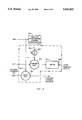
- FIG. 1 is a simplified block diagram of the control loop of an improved embodiment of the invention, with incremental and absolute compensation;
- FIG. 2 is a partial simplified schematic diagram of portions of FIG. 1;
- FIG. 3 is a partial simplified schematic diagram of other portions of FIG. 1;
- FIG. 4 is a partial simplified illustration of the internal structure of the absolute compensators, wherein the incremental feedforward compensator elements are shown in parentheses;
- FIG. 5 is a partial simplified illustration of the internal structure of the incremental compensators, wherein the incremental feedforward compensator elements are shown In parentheses;
- FIG. 6 is an abbreviated flow diagram illustrating the method and apparatus of FIGS. 2 and 3;
- FIG. 7 is a diagram illustrating the moments of a signal derivative.
- FIGS. 1, 2, and 3 The present embodiment of the invention is similar to the example previously described in U.S. patent application Ser. No. 07/355,026.
- An adaptive feedforward control method and apparatus provide a controller in which feedforward compensators tune for measured load variables.
- certain references are directed to a simplified flow diagram example, FIG. 6, illustrating the present improvements.
- the apparatus is shown schematically in FIGS. 1, 2, and 3.
- the present embodiment described includes several additional features not included in U.S. patent application Ser. No. 07/355,026. These include 1) absolute compensation; 2) detuning of feedforward compensation when feedforward and feedback would conflict; 3) adaptively tuned band-pass filtering instead of derivative filtering for identifier inputs; 4) using peak detection for sensing the end of a response to a measured load; 5) multiple stored sets of model coefficients, indexed according to conditions at the start of an isolated response, disturbance direction and subrange of a user specified variable; and 6) adapted noise threshold for each measured variable. These are described below.
- FIG. 1 A block diagram of the improved adaptive feedforward control apparatus is shown in FIG. 1.
- a secondary flow controller may adjust the manipulated flow in proportion to a measured load flow.
- the primary temperature or compensation controller adjusts the target ratio or difference of the manipulated flow to the load flow.
- FIG. 1 illustrates the use of the secondary measurement 907 (flow) for back calculation in the integral feedback path, used to avoid integrator windup when the secondary output is constrained.
- the combined controller output 938 may be used as the combined integral feedback signal 907 when a secondary controller is not used.
- blocks 902, 904, and 908 represent the feedback (primary) controller, the absolute feedforward compensator, and a process under feedforward control (such as a distillation process), respectively.
- the absolute elements are disposed above these elements, and the incremental elements are disposed below them.
- FIG. 2 A more detailed schematic representation of the PID (proportional, integral, derivative) feedback controller and incremental feedforward compensator portions of the primary controller are shown in FIG. 2, and portions of the absolute feedforward compensator are shown in FIG. 3.
- a set point signal 901 is supplied to the primary or feedback controller 902, and to the absolute adapter 926 and the incremental feedforward adapter 928.
- Primary controller 902 receives additional signals representing the controlled measurement on line 903, the incremental feedforward compensation signal on line 905, and the integral feedback signal on line 917, as will be described hereinafter.
- the absolute feedforward compensator block 904 receives the feedback and incremental feedforward controller output signal on line 918, an absolute feedforward compensation signal on line 934, an absolute feedforward measured load signal on line 942, and a secondary measurement signal or combined controller output 938 on combined integral feedback line 907, and provides a back-calculated integral feedback signal on line 917 to the feedback (primary) controller 902 and a combined controller output 938 with the set point of a secondary controller or the process manipulated variable included within process block 908.
- the secondary controller in process block 908 receives its set point input from the combined controller output on line 938 and its measurement 907 input from the process block 908. Either the secondary controller or the combined controller output on line 938 provides a control signal to the manipulated variable (valve input) of the process, also in block 908.
- the process 908 in turn provides measurement signals of the absolute feedforward measured load on line 942 and from each of possibly several incremental feedforward measured loads on a group of lines identified by 936. (The number of incremental load lines and incremental load signals is determined by the number of incremental loads in the particular configuration.)
- the process also provides the primary measurement on line 903 and the combined integral feedback on line 907.
- the internals of the primary controller 902 and absolute feedforward compensator 904 are shown generally in FIGS. 2 and 3.
- the set point signal 901 is received at the set point filter 954 (1+bIs)/(1+Is) and conveyed to summing junction block 944.
- s is the Laplace operator
- I is the controller integral time
- b is the lead-lag ratio, a tunable parameter which ranges from 0.2 to 1, depending on the process type.
- the controlled measurement signal 903 (see also FIG. 1) is similarly received at derivative filter 952 (1+1.1Ds )/(1+0.1Ds+0.5(0.1Ds ) 2 ) and conveyed to summing junction 944 where it is subtracted from the output signal from set point filter 954.
- D is the controller derivative time.
- the resultant sum signal is conveyed to the proportional band block 946 (100/P) to develop the proportional band signal 947, conveyed to summing junction 948, which junction 948 also receives an integral term 923 from integral lag block 919 (1/1+Is).
- P is the proportional band in per cent.
- the incremental feedforward compensation signal 905 is input to the integral feedback summing junction 915 which also receives the integral feedback signal present on line 917.
- the signal from summing junction 915 is the input to the integral lag block 919.
- the feedback and incremental feedforward controller output 918 is provided by summing signals on lines 947 and 923 in summer 948 and is supplied to the absolute feedforward compensator 904.
- absolute feedforward compensator 904 includes a summing junction 950, forward calculation block 913 and a back calculation block 921.
- the summing junction 950 receives the absolute feedforward measured load signal 942 and the absolute dynamic feedback compensation signal 934, the summed output of junction 950 is supplied as the denominator to back calculation block 921 via line 911 and also to forward calculation block 913.
- Forward calculation block 913 receives as its second input the feedback controller output signal 918 from junction 948. The product or sum of the two signals is limited in block 914 and output as the combined controller output signal 938.
- Back calculation block 921 also receives the combined integral feedback input 907. Its output, the integral feedback signal 917 supplied to the feedback controller 902, is either the ratio or difference of the signal on 907 and that on 911.
- the absolute feedforward dynamic compensator 910 shown in FIGS. 1, 3, and 4 receives signals from the absolute feedforward measured load 942 and the absolute feedforward adapter 926 on line 927.
- the absolute feedforward dynamic compensator 910 supplies the absolute feedforward compensation signal to the compensator 904 on line 934.
- Incremental feedforward compensator 912 receives signals from the incremental feedforward measured loads 936 and the incremental feedforward adapter 928 on line 929.
- the incremental feedforward adapter 928 supplies the incremental feedforward compensation on line 905 to the feedback (primary) controller 902 where it is accumulated with the controller integral action.
- the incremental compensation could be used to compensate for the inlet temperature or composition of a load stream, whose outlet temperature or composition is the primary controlled variable appearing on line 903.
- the absolute compensation can be used to compensate multiplicatively for the load stream flow.
- the forward calculation block 913 is a multiplier and the back calculation block 921 is a divider which divides signal 907 by signal 911.
- the moment calculating process (block 1190) of the incremental feedforward compensator 912 is triggered by sensing a significant change in an incremental feedforward measured load 936 or set point 901.
- Moments of the set of variables are related by the model equations involving unknown coefficients.
- the variables include incremental feedforward loads 936, the primary measured variable 903, and the integral feedback term 917.
- the moment calculating process (block 1190) of the absolute feedforward dynamic compensator 910 is triggered by sensing a significant change in the absolute feedforward measured load at 942 or set point 901 (start detect 1010).
- Moments of the model variables are related by model equations.
- the variables include the absolute feedforward measured load signal 942, the primary measured variable 903, and the combined integral feedback input 907, all of which are first subjected to bandpass filtering 1220 (FIG. 6).
- a set point signal 901 disturbance triggers an update for both models since this type of disturbance provides significant information for updating the model coefficients weighting the primary measurement 903.
- the closed loop characteristic time TF used to determine the expected end of an isolated response is also used to set bandpass filter parameters 1220 for each of the identified inputs, and to normalize the time scale for moment (1190) and model coefficient (projection) calculations (1200).
- the time TF is calculated (End Calculation block 1090) from the incremental model coefficients weighting the primary measurement according to equation 66 given in U.S. patent application Ser. No. 07/355,026 and equation 6 in the present embodiment.
- This feedforward detuning strategy has been selected to minimize integrated absolute error. When the feedforward contribution is reduced to zero, feedback alone is available to counter the load disturbance.
- the feedforward state is changed to "feedback (state) confirmed” 1170.
- the feedforward state is "feedback confirmed” and the feedback state changes to "state confirmed” ("quiet") or "locate peak 1" 1110
- the feedforward state is changed to "settle” 1120 pending a decision to update the feedforward adaptation. This indicates that the adaptive feedback controller considers the initial error response to be completed and a new overlapping response may be starting.
- the adaptive feedback controller state is "quiet” 1184 or if the state is "significant measured disturbance” and the time since the start of the response exceeds (for example) four times the closed-loop characteristic time at 1182, the response is considered to be completed and isolated 1080.
- the model parameters are then updated using the projection method 1200, the settled values of the measured variables are stored, and the feedforward state returned to "quiet" 1090 ("end calc”).
- model parameters 1210 are stored. Each set is indexed according to measured conditions existing at the start of a new disturbance response. When a new disturbance is detected, the conditions existing at that instant are used to select the most appropriate stored model parameter set. New values of the compensator parameters are based on these model parameters. The selected model parameters 1210 are updated at the completion of the response, provided the response is isolated.
- the conditions sensed at the beginning of each isolated response include the sign of the load change that triggered the response and the subrange of a user specified variable.
- the user specified variable range is preferably separated into three subranges using two user-specified thresholds.
- One of ordinary skill in the art will recognize that more or less subranges and user-variables could also be used.
- This approach provides a second level of adaptation for the feedforward compensators, a programmed adaptation which exploits successful past experience to cope with nonlinear process behavior.
- the set point, loads, controlled variable, and integral feedback input are converted to percent of full scale values and the state of the feedforward adapter is checked 1000.
- the state is "quiet” 1010
- the set point and measured loads are compared with their previous settled values to determine whether one has made an absolute change larger than its noise band value. See FIG. 6, block 1050. If one of these has made such an absolute change, then the changed variable and the sign of the change are noted, the state is changed to "measured disturbance", and the moment calculation is initialized, 1060.
- the noise value for each input is the sum of the user supplied noise threshold, converted to per cent of measurement range, and the signal's peak-to-peak (6 sigma in this illustrative example) noise band, which may be updated during quiet periods if desired.
- the noise update in this example is calculated as a first factor times the square root of half the average of squared-sample-to-sample differences over a second factor times the closed-loop characteristic time interval.
- the first factor is selected as six and the second factor is selected as three. This noise sigma estimate is based on the assumption that the noise components of successive sampled signal values are uncorrelated.
- the state is changed to "unmeasured disturbance", 1040. Otherwise the state remains “quiet” while waiting for the next computing interval.
- the "unmeasured disturbance” state 1040 may also be entered from other states if the error response is judged not to be isolated 1130 and 1135 or if any of the variables are out of range.
- one of six sets of stored model constants is selected based on the sign of the triggering measured-variable change and on the subrange of a user-selected variable.
- the sign index is chosen according to the predicted direction of the manipulated-variable change needed to counter the disturbance.
- the value of the user variable may fall in one of three subranges, separated by user-configured thresholds in this example.
- the user variable which could be the set point or one of the measured loads, should be selected as an indicator of the nonlinear behavior of the process. If the process is linear, the user may select a constant as the user variable, or set the thresholds to 0 and 100%.
- the model constants are used to calculate the feedforward-compensator parameters and, together with the values of the feedback controller P, I, and D tuning constants, the "closed-loop characteristic time" (TF).
- the closed-loop characteristic time (or the state of the adaptive feedback controller, if it is active) is used to estimate the time to the peak and the time to settle for an isolated error response. If the error response peak is less than the noise value or if the state is still "measured disturbance" when the time since the disturbance start exceeds 3 TF (three characteristic times) 1080, the model parameters are not updated 1090. A significant, isolated error response is needed to make a reliable model update 1200.
- the state is "measured disturbance” and the absolute error exceeds the noise threshold value NT 1140, the state is changed to "significant measured disturbance” 1150.
- Each of the feedforward compensators is a gain-delay approximated in this embodiment with a 2nd order Butterworth filter, see equation 3.
- the gain is the corresponding zero-order model parameter a10sb.
- the index, i signifies the associated load.
- the 0 index indicates zero order.
- the indices "s" and "b” indicate the particular set of stored constants associated with the disturbance sign and the user specified variable subrange.
- the delay is given by the ratio of first-order model parameter to the zero-order parameter times the scaling factor, T (see equation 5), used in the moment calculations, chosen in this example as 0.3 times TF.
- a negative delay is not physically realizable. If a negative delay is calculated, the gain is multiplied by a factor according to equation 1 which decreases linearly with negative delay, becoming zero when the negative of the calculated delay equals or exceeds half of the closed-loop characteristic time, and the delay is set to zero. This detunes the feedforward controller instead of the adaptive feedback controller, when the two otherwise would produce an overcorrection. Feedback is relied upon when nearly perfect feedforward compensation is not possible.
- the closed-loop characteristic time (TF) is the coefficient of the first order term in the closed-loop characteristic equation:
- D is the derivative time
- I is the integral time
- P is the proportional band
- N is the index for the controlled (primary measurement) variable 903.
- aN0 0. Otherwise it is the inverse gain of the process.
- feedforward compensation is calculated at each time step.
- the compensator for each variable is a gain-delay (Equation 3) with the delay approximated by a 0.7 damped quadratic (second order Butterworth), which are included in each of the compensators 910, 912,
- the quadratic is used in order to attenuate high-frequency corrections that might cause excessive valve activity with no noticeable improvement in control error. Also, the quadratic is easier to compute and requires less memory than a pure delay.
- each load signal is bandpass filtered, then compensated, and the result added together.
- the sum is then accummulated (integrated), preferably in the feedback controller, where the integrated sum is effectively added to the controller output. This allows the feedforward compensator gain terms to be updated while the process is in steady state, without ⁇ bumping ⁇ the process. Rate limiting or other internal feedback controller peculiarities may make it necessary to use a separate integrator.
- the adapter determines only the dynamic portion of the compensation. See FIG. 3.
- the adaptive dynamic term the quadratic-filtered load minus the load, is added to the measured load signal before it is applied to the feedback controller output.
- the compensation is structured in this way so that only dynamic compensation is lost when the adapter is turned off.
- the adapter-determined gain is not used. See FIGS. 2 and 3.
- Each of the measured signals used in the model-identification process, the loads, controlled variable, and integral feedback, should be subjected to band-pass filtering, 1220. This removes both low- and high-frequency components from the signals, helping to assure that time moments (weighted integrals) of isolated response signals converge to steady values in a finite time.
- a 0.7 damped filter is preferred for this purpose.
- the filter time constant in this example is adaptively programmed to be 30% of the closed-loop characteristic time, a value which may be empirically optimized.
- the zeroth and first moment integrals of the band-pass-filtered signals are updated 1190 each time step.
- the zeroth moment is the steady state signal change as shown in FIG. 7.
- the first moment is the net area under the filtered signal curve cross-hatched in FIG. 7. Filtering in the compensators 910 and 912 helps to make this area a definite finite value, since it makes the filtered signal final value approach zero.
- the first moment is weighted by the scaling factor, 1/T.
- This scaling factor may be empirically optimized: T is selected at 30% of the closed-loop characteristic time for this example. It scales and eliminates the time dimension from the model coefficients 1200, which are calculated from the moments 1190. Each coefficient is thereby made to have the same units and expected value range. This improves the convergence rate of the projection method.
- the moment integrals must converge to a finite value in a finite time in order for the moment values to be insensitive to the time of integral termination. Because noise is not completely removed by filtering, high-order moments are much more sensitive to the termination time because of heavy weighting (by time to the power of the moment order).
- Each of the measured process variables is characterized by zero and first order moments. These moments are directly related to Taylor series coefficients of the bandpass filtered signal's x ⁇ t ⁇ Laplace transform, X ⁇ s ⁇ , as in equation 7.
- the process output is related to the process inputs with a model.
- the form of the model equations is chosen to simplify the subsequent compensator design calculation, as in equation 8.
- N is the number of measured loads whose index i ranges from 0 to N-1
- N is the index of the controlled variable
- N+1 is the index of the integral feedback input (or controller output)
- N+2 is the index for the combined integral feedback (or combined controller output).
- Equating the terms multiplying the same powers of s yields two equations when only powers less than two are considered (equations 10 and 11):
- the projection method finds the new values of the model parameters that satisfy the two equations and minimize the sum of squared model-parameter changes. Only those model parameters that multiply nonzero moment values can influence the model equation errors. Constant load variables have zero moment values. Therefore, model parameters associated with constant load variables will not be updated. Typically, the parameters that will change the most are those that multiply the largest moment values.
- noise must be effectively removed from the process data so that it is reasonable to satisfy the model equations exactly. This is done by continuing the moment integrations of the filtered signals for an isolated response until the values no longer change significantly.
- the current set of model parameters can be represented by a point in a multidimensional parameter space. Along each of the orthogonal coordinate axes, all but one of the model parameters is zero. The locus of parameter combinations that satisfy the two model equations form a subspace. The projection method finds the point in the subspace that is closest to the point for the current model parameter set. For distance to be significant, the units and the expected range of all the model parameters should be the same.
- the parameter values are made dimensionless in this example by converting all of the signals from engineering units to percent of range and by normalizing the time scale with the factor, T, selected to equal 30% of the closed-loop characteristic time TF in the present illustrative example in order to achieve fast convergence.
- the first step in the projection calculation is to determine the errors in the model equations using the current model parameters, equations 12 and 13.
- the parameter see is introduced to reduce the model parameter correction when the error response is not much greater than the noise value. It represents an unmeasured and unmodeled load step at the start of the disturbance with magnitude equal to the noise value. Thus, see is the square of the noise value.
- model parameters are then updated (i ranges from 0 to N), equations 20 and 21.
Abstract
Description
Claims (51)
Priority Applications (1)
| Application Number | Priority Date | Filing Date | Title |
|---|---|---|---|
| US08/097,916 US5541833A (en) | 1987-03-30 | 1993-07-28 | Multivariable feedforward adaptive controller |
Applications Claiming Priority (4)
| Application Number | Priority Date | Filing Date | Title |
|---|---|---|---|
| US3196487A | 1987-03-30 | 1987-03-30 | |
| US07/355,026 US5043863A (en) | 1987-03-30 | 1989-05-02 | Multivariable adaptive feedforward controller |
| US75013391A | 1991-08-26 | 1991-08-26 | |
| US08/097,916 US5541833A (en) | 1987-03-30 | 1993-07-28 | Multivariable feedforward adaptive controller |
Related Parent Applications (1)
| Application Number | Title | Priority Date | Filing Date |
|---|---|---|---|
| US75013391A Continuation | 1987-03-30 | 1991-08-26 |
Publications (1)
| Publication Number | Publication Date |
|---|---|
| US5541833A true US5541833A (en) | 1996-07-30 |
Family
ID=27363997
Family Applications (1)
| Application Number | Title | Priority Date | Filing Date |
|---|---|---|---|
| US08/097,916 Expired - Lifetime US5541833A (en) | 1987-03-30 | 1993-07-28 | Multivariable feedforward adaptive controller |
Country Status (1)
| Country | Link |
|---|---|
| US (1) | US5541833A (en) |
Cited By (80)
| Publication number | Priority date | Publication date | Assignee | Title |
|---|---|---|---|---|
| US5848535A (en) * | 1997-03-24 | 1998-12-15 | Gas Research Institute | Control system having a binomial setpoint filter |
| EP0915301A2 (en) * | 1997-11-07 | 1999-05-12 | LANDIS & STAEFA, INC. | Room temperature control apparatus having feedforward and feedback control and method |
| EP0915300A2 (en) * | 1997-11-07 | 1999-05-12 | LANDIS & STAEFA, INC. | Room pressure control apparatus having feedforward and feedback control and method |
| DE19846447A1 (en) * | 1998-10-08 | 2000-04-13 | Siemens Ag | Control unit for control of segment with several coupled controlled variables |
| WO2000023856A1 (en) * | 1998-10-16 | 2000-04-27 | General Cybernation Group, Inc. | Model-free adaptive control for flexible production systems |
| US6155283A (en) * | 1999-09-10 | 2000-12-05 | The Foxboro Company | Intelligent valve positioner tuning |
| US6198246B1 (en) | 1999-08-19 | 2001-03-06 | Siemens Energy & Automation, Inc. | Method and apparatus for tuning control system parameters |
| FR2810695A1 (en) * | 2000-06-22 | 2001-12-28 | Sagem | METHOD FOR ORDERING A MOTORIZED BUTTERFLY SHUTTER |
| US6442445B1 (en) | 1999-03-19 | 2002-08-27 | International Business Machines Corporation, | User configurable multivariate time series reduction tool control method |
| US20020123856A1 (en) * | 2001-03-01 | 2002-09-05 | Evren Eryurek | Cavitation detection in a process plant |
| US20020147506A1 (en) * | 2001-03-01 | 2002-10-10 | Evren Eryurek | Fiducial technique for estimating and using degradation levels in a process plant |
| US6470225B1 (en) | 1999-04-16 | 2002-10-22 | Siemens Energy & Automation, Inc. | Method and apparatus for automatically tuning feedforward parameters |
| US20030014500A1 (en) * | 2001-07-10 | 2003-01-16 | Schleiss Trevor D. | Transactional data communications for process control systems |
| US6571135B2 (en) | 1998-10-08 | 2003-05-27 | Siemens Aktiengesellschaft | Control unit for controlling a system with several coupled variables |
| US20040054427A1 (en) * | 2000-11-15 | 2004-03-18 | Mikael Petersson | Method and a system for evaluating whether a signal is suitable for feed-forward control |
| US20040111499A1 (en) * | 2002-12-10 | 2004-06-10 | Dobrowski Patrick M. | Method for launching applications |
| US20040158474A1 (en) * | 2003-02-06 | 2004-08-12 | Karschnia Robert J. | Service facility for providing remote diagnostic and maintenance services to a process plant |
| US20040181364A1 (en) * | 2003-03-13 | 2004-09-16 | Csi Technology, Inc. | Generation of data indicative of machine operational condition |
| US6795798B2 (en) | 2001-03-01 | 2004-09-21 | Fisher-Rosemount Systems, Inc. | Remote analysis of process control plant data |
| US20040186927A1 (en) * | 2003-03-18 | 2004-09-23 | Evren Eryurek | Asset optimization reporting in a process plant |
| US20040230328A1 (en) * | 2003-03-21 | 2004-11-18 | Steve Armstrong | Remote data visualization within an asset data system for a process plant |
| US20040249481A1 (en) * | 2003-03-21 | 2004-12-09 | Qinsheng Zheng | Methods and articles for detecting, verifying, and repairing collinearity in a model or subsets of a model |
| US20040255057A1 (en) * | 2003-06-16 | 2004-12-16 | Greg Opheim | Method and apparatus for providing help information in multiple formats |
| US20050137721A1 (en) * | 2003-12-22 | 2005-06-23 | Attarwala Fakhruddin T. | Use of core process models in model predictive controller |
| US20050190054A1 (en) * | 2004-02-26 | 2005-09-01 | Cindy Scott | Method and system for integrated alarms in a process control system |
| US20050197806A1 (en) * | 2004-03-03 | 2005-09-08 | Fisher-Rosemount Systems, Inc. | Configuration system and method for abnormal situation prevention in a process plant |
| US20050197803A1 (en) * | 2004-03-03 | 2005-09-08 | Fisher-Rosemount Systems, Inc. | Abnormal situation prevention in a process plant |
| US20050197805A1 (en) * | 2001-03-01 | 2005-09-08 | Fisher-Rosemount Systems, Inc. | Data presentation system for abnormal situation prevention in a process plant |
| US20050209713A1 (en) * | 2004-03-16 | 2005-09-22 | Fuller James W | Model predictive controller with life extending control |
| US20050222698A1 (en) * | 2004-03-30 | 2005-10-06 | Fisher-Rosemount Systems, Inc. | Integrated configuration system for use in a process plant |
| US20050267709A1 (en) * | 2004-05-28 | 2005-12-01 | Fisher-Rosemount Systems, Inc. | System and method for detecting an abnormal situation associated with a heater |
| US20050267710A1 (en) * | 2004-05-28 | 2005-12-01 | Fisher-Rosemount Systems, Inc. | System and method for detecting an abnormal situation associated with a heater |
| US20050273204A1 (en) * | 2000-02-14 | 2005-12-08 | Invensys Systems, Inc., A Massachusetts Corporation | Intelligent valve flow linearization |
| US6975219B2 (en) | 2001-03-01 | 2005-12-13 | Fisher-Rosemount Systems, Inc. | Enhanced hart device alerts in a process control system |
| US20060064182A1 (en) * | 2004-09-17 | 2006-03-23 | Fisher-Rosemount Systems, Inc. | System and method for detecting an abnormal situation associated with a reactor |
| US20060126367A1 (en) * | 2004-12-14 | 2006-06-15 | Hesterman Bryce L | Power supply adaptive feedforward control circuit |
| US7103427B2 (en) | 2003-02-28 | 2006-09-05 | Fisher-Rosemont Systems, Inc. | Delivery of process plant notifications |
| US20060223451A1 (en) * | 2005-03-31 | 2006-10-05 | Joshua Posamentier | Transceiver with receive path overload protection and method |
| US7152072B2 (en) | 2003-01-08 | 2006-12-19 | Fisher-Rosemount Systems Inc. | Methods and apparatus for importing device data into a database system used in a process plant |
| US20080027678A1 (en) * | 2006-07-25 | 2008-01-31 | Fisher-Rosemount Systems, Inc. | Method and system for detecting abnormal operation in a process plant |
| US20080027677A1 (en) * | 2006-07-25 | 2008-01-31 | Fisher-Rosemount Systems, Inc. | Methods and systems for detecting deviation of a process variable from expected values |
| US20080077257A1 (en) * | 2006-09-22 | 2008-03-27 | Peterson Tod J | Model predictive controller solution analysis process |
| US20080082182A1 (en) * | 2006-09-29 | 2008-04-03 | Brother Kogyo Kabushiki Kaisha | Adaptive control device, image forming apparatus, and recording medium |
| US20080125879A1 (en) * | 2006-07-25 | 2008-05-29 | Fisher-Rosemount Systems, Inc. | Method and system for detecting abnormal operation of a level regulatory control loop |
| US20080167839A1 (en) * | 2007-01-04 | 2008-07-10 | Fisher-Rosemount Systems, Inc. | Method and System for Modeling a Process in a Process Plant |
| US20080188972A1 (en) * | 2006-10-11 | 2008-08-07 | Fisher-Rosemount Systems, Inc. | Method and System for Detecting Faults in a Process Plant |
| US20080288321A1 (en) * | 2007-05-15 | 2008-11-20 | Fisher-Rosemount Systems, Inc. | Automatic maintenance estimation in a plant environment |
| US7493310B2 (en) | 2002-12-30 | 2009-02-17 | Fisher-Rosemount Systems, Inc. | Data visualization within an integrated asset data system for a process plant |
| US20090224717A1 (en) * | 2008-03-07 | 2009-09-10 | Fuji Machine Mfg. Co., Ltd. | Operating apparatus |
| US20090299499A1 (en) * | 2001-06-05 | 2009-12-03 | Florentin Woergoetter | Correction Signals |
| US7660701B2 (en) | 2004-06-12 | 2010-02-09 | Fisher-Rosemount Systems, Inc. | System and method for detecting an abnormal situation associated with a process gain of a control loop |
| US7702401B2 (en) | 2007-09-05 | 2010-04-20 | Fisher-Rosemount Systems, Inc. | System for preserving and displaying process control data associated with an abnormal situation |
| US20100174512A1 (en) * | 2009-01-08 | 2010-07-08 | Jonas Berggren | Method and Apparatus for Creating a Generalized Response Model for a Sheet Forming Machine |
| US20100179791A1 (en) * | 2009-01-12 | 2010-07-15 | Andreas Zehnpfund | Method and Apparatus for Creating a Comprehensive Response Model for a Sheet Forming Machine |
| US20100198364A1 (en) * | 2009-02-05 | 2010-08-05 | Shih-Chin Chen | Configurable Multivariable Control System |
| US7827006B2 (en) | 2007-01-31 | 2010-11-02 | Fisher-Rosemount Systems, Inc. | Heat exchanger fouling detection |
| US7853339B2 (en) | 2006-09-29 | 2010-12-14 | Fisher-Rosemount Systems, Inc. | Statistical signatures used with multivariate analysis for steady-state detection in a process |
| US7953842B2 (en) | 2003-02-19 | 2011-05-31 | Fisher-Rosemount Systems, Inc. | Open network-based data acquisition, aggregation and optimization for use with process control systems |
| US8005647B2 (en) | 2005-04-08 | 2011-08-23 | Rosemount, Inc. | Method and apparatus for monitoring and performing corrective measures in a process plant using monitoring data with corrective measures data |
| US8032340B2 (en) | 2007-01-04 | 2011-10-04 | Fisher-Rosemount Systems, Inc. | Method and system for modeling a process variable in a process plant |
| US8044793B2 (en) | 2001-03-01 | 2011-10-25 | Fisher-Rosemount Systems, Inc. | Integrated device alerts in a process control system |
| US8055479B2 (en) | 2007-10-10 | 2011-11-08 | Fisher-Rosemount Systems, Inc. | Simplified algorithm for abnormal situation prevention in load following applications including plugged line diagnostics in a dynamic process |
| US8073967B2 (en) | 2002-04-15 | 2011-12-06 | Fisher-Rosemount Systems, Inc. | Web services-based communications for use with process control systems |
| US20110301724A1 (en) * | 2010-06-04 | 2011-12-08 | Flavio Tondolo | Modified proportional integral derivative controller |
| US8301676B2 (en) | 2007-08-23 | 2012-10-30 | Fisher-Rosemount Systems, Inc. | Field device with capability of calculating digital filter coefficients |
| US8417595B2 (en) | 2001-03-01 | 2013-04-09 | Fisher-Rosemount Systems, Inc. | Economic calculations in a process control system |
| US8606544B2 (en) | 2006-07-25 | 2013-12-10 | Fisher-Rosemount Systems, Inc. | Methods and systems for detecting deviation of a process variable from expected values |
| US20140088787A1 (en) * | 2012-09-24 | 2014-03-27 | Nestec S.A. | Methods and systems for energy balance control for feed flow and feed temperature disturbances |
| US8762106B2 (en) | 2006-09-28 | 2014-06-24 | Fisher-Rosemount Systems, Inc. | Abnormal situation prevention in a heat exchanger |
| US20140195013A1 (en) * | 2002-04-18 | 2014-07-10 | Cleveland State University | Extended active disturbance rejection controller |
| US8935298B2 (en) | 2002-12-30 | 2015-01-13 | Fisher-Rosemount Systems, Inc. | Integrated navigational tree importation and generation in a process plant |
| US9201420B2 (en) | 2005-04-08 | 2015-12-01 | Rosemount, Inc. | Method and apparatus for performing a function in a process plant using monitoring data with criticality evaluation data |
| US9323247B2 (en) | 2007-09-14 | 2016-04-26 | Fisher-Rosemount Systems, Inc. | Personalized plant asset data representation and search system |
| US9529348B2 (en) | 2012-01-24 | 2016-12-27 | Emerson Process Management Power & Water Solutions, Inc. | Method and apparatus for deploying industrial plant simulators using cloud computing technologies |
| US9582754B1 (en) | 2016-05-17 | 2017-02-28 | Roger Collins | Adaptive feed forward method for temperature control |
| US9715221B2 (en) | 2014-05-01 | 2017-07-25 | Aspen Technology, Inc. | Online control calculation for models containing near colinearity and uncertainty |
| US9927788B2 (en) | 2011-05-19 | 2018-03-27 | Fisher-Rosemount Systems, Inc. | Software lockout coordination between a process control system and an asset management system |
| CN113401366A (en) * | 2021-06-17 | 2021-09-17 | 北京控制工程研究所 | Strong anti-interference composite control method for overcoming influence of periodic moving parts |
| CN113717757A (en) * | 2021-11-03 | 2021-11-30 | 华能(天津)煤气化发电有限公司 | Variable proportion feedback adjustment method for pulverized coal pressurized conveying |
| CN115145337A (en) * | 2022-07-27 | 2022-10-04 | 沈阳农业大学 | Plant factory temperature and humidity control method and system |
Citations (25)
| Publication number | Priority date | Publication date | Assignee | Title |
|---|---|---|---|---|
| US3798426A (en) * | 1971-12-20 | 1974-03-19 | Foxboro Co | Pattern evaluation method and apparatus for adaptive control |
| US3934124A (en) * | 1974-06-24 | 1976-01-20 | Gabriel Edwin Z | Self-organizing controllers |
| US4006346A (en) * | 1975-11-13 | 1977-02-01 | Phillips Petroleum Company | Control method including feedforward signal |
| US4349869A (en) * | 1979-10-01 | 1982-09-14 | Shell Oil Company | Dynamic matrix control method |
| FR2524169A1 (en) * | 1982-03-26 | 1983-09-30 | Tokyo Shibaura Electric Co | METHOD AND SYSTEM FOR CONDUCTING PROCESSES |
| US4451878A (en) * | 1980-07-18 | 1984-05-29 | Tokyo Shibaura Denki Kabushiki Kaisha | Process control apparatus |
| US4489376A (en) * | 1982-04-12 | 1984-12-18 | Westinghouse Electric Corp. | Industrial process control apparatus and method |
| EP0152871A2 (en) * | 1984-02-07 | 1985-08-28 | Kabushiki Kaisha Toshiba | Process control apparatus |
| US4555757A (en) * | 1983-05-05 | 1985-11-26 | Westinghouse Electric Corp. | Interface system for hybrid control loops |
| JPS60263207A (en) * | 1984-06-12 | 1985-12-26 | Toshiba Corp | Process control device |
| US4602326A (en) * | 1983-12-12 | 1986-07-22 | The Foxboro Company | Pattern-recognizing self-tuning controller |
| US4651272A (en) * | 1985-06-03 | 1987-03-17 | Vickers, Incorporated | Power transmission |
| JPS6346502A (en) * | 1986-08-14 | 1988-02-27 | Yokogawa Electric Corp | Pid controller |
| US4754410A (en) * | 1986-02-06 | 1988-06-28 | Westinghouse Electric Corp. | Automated rule based process control method with feedback and apparatus therefor |
| WO1988007708A1 (en) * | 1987-03-30 | 1988-10-06 | The Foxboro Company | Multivariable adaptive feedforward controller |
| US4855897A (en) * | 1987-07-13 | 1989-08-08 | The Foxboro Company | Method and apparatus for statistical set point bias control |
| US4864490A (en) * | 1986-04-11 | 1989-09-05 | Mitsubishi Denki Kabushiki Kaisha | Auto-tuning controller using fuzzy reasoning to obtain optimum control parameters |
| JPH01239603A (en) * | 1988-03-18 | 1989-09-25 | Toshiba Corp | Process controller |
| US4903192A (en) * | 1987-04-03 | 1990-02-20 | Hitachi, Ltd. | Pid controller system |
| US4951191A (en) * | 1987-06-26 | 1990-08-21 | Kabushiki Kaisha Toshiba | Process control having improved combination of feedforward feedback control |
| US5043862A (en) * | 1988-04-07 | 1991-08-27 | Hitachi, Ltd. | Method and apparatus of automatically setting PID constants |
| US5079691A (en) * | 1988-05-14 | 1992-01-07 | Robert Bosch Gmbh | Control process and apparatus, in particular lambda control |
| WO1992007023A1 (en) * | 1990-10-22 | 1992-04-30 | Berol Nobel Ab | Hydrophilised solid surface, method for the production thereof, and agent therefor |
| US5153807A (en) * | 1988-09-21 | 1992-10-06 | Hitachi, Ltd. | Self-tuning controller apparatus and process control system |
| US5166873A (en) * | 1989-09-13 | 1992-11-24 | Yokogawa Electric Corporation | Process control device |
-
1993
- 1993-07-28 US US08/097,916 patent/US5541833A/en not_active Expired - Lifetime
Patent Citations (28)
| Publication number | Priority date | Publication date | Assignee | Title |
|---|---|---|---|---|
| US3798426A (en) * | 1971-12-20 | 1974-03-19 | Foxboro Co | Pattern evaluation method and apparatus for adaptive control |
| US3934124A (en) * | 1974-06-24 | 1976-01-20 | Gabriel Edwin Z | Self-organizing controllers |
| US4006346A (en) * | 1975-11-13 | 1977-02-01 | Phillips Petroleum Company | Control method including feedforward signal |
| US4349869A (en) * | 1979-10-01 | 1982-09-14 | Shell Oil Company | Dynamic matrix control method |
| US4451878A (en) * | 1980-07-18 | 1984-05-29 | Tokyo Shibaura Denki Kabushiki Kaisha | Process control apparatus |
| US4563735A (en) * | 1982-03-26 | 1986-01-07 | Tokyo Shibaura Denki Kabushiki Kaisha | Process controlling method and system involving separate determination of static and dynamic compensation components |
| FR2524169A1 (en) * | 1982-03-26 | 1983-09-30 | Tokyo Shibaura Electric Co | METHOD AND SYSTEM FOR CONDUCTING PROCESSES |
| US4489376A (en) * | 1982-04-12 | 1984-12-18 | Westinghouse Electric Corp. | Industrial process control apparatus and method |
| US4555757A (en) * | 1983-05-05 | 1985-11-26 | Westinghouse Electric Corp. | Interface system for hybrid control loops |
| US4602326A (en) * | 1983-12-12 | 1986-07-22 | The Foxboro Company | Pattern-recognizing self-tuning controller |
| US4698745A (en) * | 1984-02-07 | 1987-10-06 | Kabushiki Kaisha Toshiba | Process control apparatus for optimal adaptation to a disturbance |
| EP0152871A2 (en) * | 1984-02-07 | 1985-08-28 | Kabushiki Kaisha Toshiba | Process control apparatus |
| JPS60263207A (en) * | 1984-06-12 | 1985-12-26 | Toshiba Corp | Process control device |
| US4651272A (en) * | 1985-06-03 | 1987-03-17 | Vickers, Incorporated | Power transmission |
| US4754410A (en) * | 1986-02-06 | 1988-06-28 | Westinghouse Electric Corp. | Automated rule based process control method with feedback and apparatus therefor |
| US4864490A (en) * | 1986-04-11 | 1989-09-05 | Mitsubishi Denki Kabushiki Kaisha | Auto-tuning controller using fuzzy reasoning to obtain optimum control parameters |
| JPS6346502A (en) * | 1986-08-14 | 1988-02-27 | Yokogawa Electric Corp | Pid controller |
| WO1988007708A1 (en) * | 1987-03-30 | 1988-10-06 | The Foxboro Company | Multivariable adaptive feedforward controller |
| US4903192A (en) * | 1987-04-03 | 1990-02-20 | Hitachi, Ltd. | Pid controller system |
| US4951191A (en) * | 1987-06-26 | 1990-08-21 | Kabushiki Kaisha Toshiba | Process control having improved combination of feedforward feedback control |
| US4855897A (en) * | 1987-07-13 | 1989-08-08 | The Foxboro Company | Method and apparatus for statistical set point bias control |
| JPH01239603A (en) * | 1988-03-18 | 1989-09-25 | Toshiba Corp | Process controller |
| US5029066A (en) * | 1988-03-18 | 1991-07-02 | Kabushiki Kaisha Toshiba | Process control system |
| US5043862A (en) * | 1988-04-07 | 1991-08-27 | Hitachi, Ltd. | Method and apparatus of automatically setting PID constants |
| US5079691A (en) * | 1988-05-14 | 1992-01-07 | Robert Bosch Gmbh | Control process and apparatus, in particular lambda control |
| US5153807A (en) * | 1988-09-21 | 1992-10-06 | Hitachi, Ltd. | Self-tuning controller apparatus and process control system |
| US5166873A (en) * | 1989-09-13 | 1992-11-24 | Yokogawa Electric Corporation | Process control device |
| WO1992007023A1 (en) * | 1990-10-22 | 1992-04-30 | Berol Nobel Ab | Hydrophilised solid surface, method for the production thereof, and agent therefor |
Non-Patent Citations (8)
| Title |
|---|
| E. H. Bristol, et al., "Moment Projection Feedforward Control Adaptation", The Foxboro Company, Research Department, Foxbora, MA; (Date Unknown). |
| E. H. Bristol, et al., Moment Projection Feedforward Control Adaptation , The Foxboro Company, Research Department, Foxbora, MA; (Date Unknown). * |
| F. Radke, "Microprocessor-Based Adaptive Pid-Controllers", ISA Transactions, V 27n.2 (1988) pp. 43-50. |
| F. Radke, Microprocessor Based Adaptive Pid Controllers , ISA Transactions, V 27n.2 (1988) pp. 43 50. * |
| Katsuhiko Ogata, "Modern Control Engineering", Prentice-Hall Electrical Engineering Series, University of Minnesota, 1970. |
| Katsuhiko Ogata, Modern Control Engineering , Prentice Hall Electrical Engineering Series, University of Minnesota, 1970. * |
| Mauricio Alves da Silva, et al., "A Rule Based Procedure for Selftuning Pid Controllers", Pro. 27th IEEE Conf. on Decision and Control, vol. 313, pp. 1947-1951, 1988. |
| Mauricio Alves da Silva, et al., A Rule Based Procedure for Selftuning Pid Controllers , Pro. 27th IEEE Conf. on Decision and Control, vol. 313, pp. 1947 1951, 1988. * |
Cited By (140)
| Publication number | Priority date | Publication date | Assignee | Title |
|---|---|---|---|---|
| US5848535A (en) * | 1997-03-24 | 1998-12-15 | Gas Research Institute | Control system having a binomial setpoint filter |
| EP0915301A3 (en) * | 1997-11-07 | 2002-05-15 | Siemens Building Technologies, Inc. | Room temperature control apparatus having feedforward and feedback control and method |
| EP0915301A2 (en) * | 1997-11-07 | 1999-05-12 | LANDIS & STAEFA, INC. | Room temperature control apparatus having feedforward and feedback control and method |
| EP0915300A2 (en) * | 1997-11-07 | 1999-05-12 | LANDIS & STAEFA, INC. | Room pressure control apparatus having feedforward and feedback control and method |
| EP0915300A3 (en) * | 1997-11-07 | 2001-11-28 | Siemens Building Technologies, Inc. | Room pressure control apparatus having feedforward and feedback control and method |
| DE19846447A1 (en) * | 1998-10-08 | 2000-04-13 | Siemens Ag | Control unit for control of segment with several coupled controlled variables |
| US6571135B2 (en) | 1998-10-08 | 2003-05-27 | Siemens Aktiengesellschaft | Control unit for controlling a system with several coupled variables |
| WO2000023856A1 (en) * | 1998-10-16 | 2000-04-27 | General Cybernation Group, Inc. | Model-free adaptive control for flexible production systems |
| US6442445B1 (en) | 1999-03-19 | 2002-08-27 | International Business Machines Corporation, | User configurable multivariate time series reduction tool control method |
| US6584368B2 (en) | 1999-03-19 | 2003-06-24 | International Business Machines Corporation | User configurable multivariate time series reduction tool control method |
| US6678569B2 (en) | 1999-03-19 | 2004-01-13 | International Business Machines Corporation | User configurable multivariate time series reduction tool control method |
| US6470225B1 (en) | 1999-04-16 | 2002-10-22 | Siemens Energy & Automation, Inc. | Method and apparatus for automatically tuning feedforward parameters |
| US6198246B1 (en) | 1999-08-19 | 2001-03-06 | Siemens Energy & Automation, Inc. | Method and apparatus for tuning control system parameters |
| US6155283A (en) * | 1999-09-10 | 2000-12-05 | The Foxboro Company | Intelligent valve positioner tuning |
| US7096093B1 (en) | 2000-02-14 | 2006-08-22 | Invensys Systems, Inc. | Intelligent valve flow linearization |
| US7266427B2 (en) | 2000-02-14 | 2007-09-04 | Invensys Systems, Inc. | Intelligent valve flow linearization |
| US20050273204A1 (en) * | 2000-02-14 | 2005-12-08 | Invensys Systems, Inc., A Massachusetts Corporation | Intelligent valve flow linearization |
| FR2810695A1 (en) * | 2000-06-22 | 2001-12-28 | Sagem | METHOD FOR ORDERING A MOTORIZED BUTTERFLY SHUTTER |
| US20040054427A1 (en) * | 2000-11-15 | 2004-03-18 | Mikael Petersson | Method and a system for evaluating whether a signal is suitable for feed-forward control |
| US6937910B2 (en) * | 2000-11-15 | 2005-08-30 | Abb Ab | Method and a system for evaluating whether a signal is suitable for feed-forward control |
| US6813532B2 (en) | 2001-03-01 | 2004-11-02 | Fisher-Rosemount Systems, Inc. | Creation and display of indices within a process plant |
| US6965806B2 (en) | 2001-03-01 | 2005-11-15 | Fisher-Rosemount Systems Inc. | Automatic work order/parts order generation and tracking |
| US6795798B2 (en) | 2001-03-01 | 2004-09-21 | Fisher-Rosemount Systems, Inc. | Remote analysis of process control plant data |
| US8044793B2 (en) | 2001-03-01 | 2011-10-25 | Fisher-Rosemount Systems, Inc. | Integrated device alerts in a process control system |
| US8417595B2 (en) | 2001-03-01 | 2013-04-09 | Fisher-Rosemount Systems, Inc. | Economic calculations in a process control system |
| US20020123856A1 (en) * | 2001-03-01 | 2002-09-05 | Evren Eryurek | Cavitation detection in a process plant |
| US8620779B2 (en) | 2001-03-01 | 2013-12-31 | Fisher-Rosemount Systems, Inc. | Economic calculations in a process control system |
| US7957936B2 (en) | 2001-03-01 | 2011-06-07 | Fisher-Rosemount Systems, Inc. | Presentation system for abnormal situation prevention in a process plant |
| US7389204B2 (en) | 2001-03-01 | 2008-06-17 | Fisher-Rosemount Systems, Inc. | Data presentation system for abnormal situation prevention in a process plant |
| US20080168356A1 (en) * | 2001-03-01 | 2008-07-10 | Fisher-Rosemount System, Inc. | Presentation system for abnormal situation prevention in a process plant |
| US6925338B2 (en) | 2001-03-01 | 2005-08-02 | Fisher-Rosemount Systems, Inc. | Fiducial technique for estimating and using degradation levels in a process plant |
| US6975219B2 (en) | 2001-03-01 | 2005-12-13 | Fisher-Rosemount Systems, Inc. | Enhanced hart device alerts in a process control system |
| US20020147506A1 (en) * | 2001-03-01 | 2002-10-10 | Evren Eryurek | Fiducial technique for estimating and using degradation levels in a process plant |
| US6954713B2 (en) | 2001-03-01 | 2005-10-11 | Fisher-Rosemount Systems, Inc. | Cavitation detection in a process plant |
| US20050197805A1 (en) * | 2001-03-01 | 2005-09-08 | Fisher-Rosemount Systems, Inc. | Data presentation system for abnormal situation prevention in a process plant |
| US8032237B2 (en) * | 2001-06-05 | 2011-10-04 | Elverson Hopewell Llc | Correction signal capable of diminishing a future change to an output signal |
| US20090299499A1 (en) * | 2001-06-05 | 2009-12-03 | Florentin Woergoetter | Correction Signals |
| US20030014500A1 (en) * | 2001-07-10 | 2003-01-16 | Schleiss Trevor D. | Transactional data communications for process control systems |
| US7162534B2 (en) | 2001-07-10 | 2007-01-09 | Fisher-Rosemount Systems, Inc. | Transactional data communications for process control systems |
| US9760651B2 (en) | 2002-04-15 | 2017-09-12 | Fisher-Rosemount Systems, Inc. | Web services-based communications for use with process control systems |
| US8073967B2 (en) | 2002-04-15 | 2011-12-06 | Fisher-Rosemount Systems, Inc. | Web services-based communications for use with process control systems |
| US9094470B2 (en) | 2002-04-15 | 2015-07-28 | Fisher-Rosemount Systems, Inc. | Web services-based communications for use with process control systems |
| US20140195013A1 (en) * | 2002-04-18 | 2014-07-10 | Cleveland State University | Extended active disturbance rejection controller |
| US9268315B2 (en) * | 2002-04-18 | 2016-02-23 | Cleveland State University | Extended active disturbance rejection controller |
| US7600234B2 (en) | 2002-12-10 | 2009-10-06 | Fisher-Rosemount Systems, Inc. | Method for launching applications |
| US20040111499A1 (en) * | 2002-12-10 | 2004-06-10 | Dobrowski Patrick M. | Method for launching applications |
| US8935298B2 (en) | 2002-12-30 | 2015-01-13 | Fisher-Rosemount Systems, Inc. | Integrated navigational tree importation and generation in a process plant |
| US7493310B2 (en) | 2002-12-30 | 2009-02-17 | Fisher-Rosemount Systems, Inc. | Data visualization within an integrated asset data system for a process plant |
| US7152072B2 (en) | 2003-01-08 | 2006-12-19 | Fisher-Rosemount Systems Inc. | Methods and apparatus for importing device data into a database system used in a process plant |
| US20040158474A1 (en) * | 2003-02-06 | 2004-08-12 | Karschnia Robert J. | Service facility for providing remote diagnostic and maintenance services to a process plant |
| US7953842B2 (en) | 2003-02-19 | 2011-05-31 | Fisher-Rosemount Systems, Inc. | Open network-based data acquisition, aggregation and optimization for use with process control systems |
| US7103427B2 (en) | 2003-02-28 | 2006-09-05 | Fisher-Rosemont Systems, Inc. | Delivery of process plant notifications |
| US6915235B2 (en) | 2003-03-13 | 2005-07-05 | Csi Technology, Inc. | Generation of data indicative of machine operational condition |
| US20040181364A1 (en) * | 2003-03-13 | 2004-09-16 | Csi Technology, Inc. | Generation of data indicative of machine operational condition |
| US20040186927A1 (en) * | 2003-03-18 | 2004-09-23 | Evren Eryurek | Asset optimization reporting in a process plant |
| US8620618B2 (en) | 2003-03-18 | 2013-12-31 | Fisher-Rosemount Systems, Inc. | Asset optimization reporting in a process plant |
| US7634384B2 (en) | 2003-03-18 | 2009-12-15 | Fisher-Rosemount Systems, Inc. | Asset optimization reporting in a process plant |
| US20040249481A1 (en) * | 2003-03-21 | 2004-12-09 | Qinsheng Zheng | Methods and articles for detecting, verifying, and repairing collinearity in a model or subsets of a model |
| US7231264B2 (en) * | 2003-03-21 | 2007-06-12 | Aspen Technology, Inc. | Methods and articles for detecting, verifying, and repairing collinearity in a model or subsets of a model |
| US20070100477A9 (en) * | 2003-03-21 | 2007-05-03 | Qingsheng Zheng | Methods and articles for detecting, verifying, and repairing collinearity in a model or subsets of a model |
| US20040230328A1 (en) * | 2003-03-21 | 2004-11-18 | Steve Armstrong | Remote data visualization within an asset data system for a process plant |
| US20060015194A9 (en) * | 2003-03-21 | 2006-01-19 | Qingsheng Zheng | Methods and articles for detecting, verifying, and repairing collinearity in a model or subsets of a model |
| US7299415B2 (en) | 2003-06-16 | 2007-11-20 | Fisher-Rosemount Systems, Inc. | Method and apparatus for providing help information in multiple formats |
| US20040255057A1 (en) * | 2003-06-16 | 2004-12-16 | Greg Opheim | Method and apparatus for providing help information in multiple formats |
| US7187989B2 (en) * | 2003-12-22 | 2007-03-06 | Fakhruddin T Attarwala | Use of core process models in model predictive controller |
| US20050137721A1 (en) * | 2003-12-22 | 2005-06-23 | Attarwala Fakhruddin T. | Use of core process models in model predictive controller |
| US20050190054A1 (en) * | 2004-02-26 | 2005-09-01 | Cindy Scott | Method and system for integrated alarms in a process control system |
| US7030747B2 (en) | 2004-02-26 | 2006-04-18 | Fisher-Rosemount Systems, Inc. | Method and system for integrated alarms in a process control system |
| US7676287B2 (en) | 2004-03-03 | 2010-03-09 | Fisher-Rosemount Systems, Inc. | Configuration system and method for abnormal situation prevention in a process plant |
| US7079984B2 (en) | 2004-03-03 | 2006-07-18 | Fisher-Rosemount Systems, Inc. | Abnormal situation prevention in a process plant |
| US20050197803A1 (en) * | 2004-03-03 | 2005-09-08 | Fisher-Rosemount Systems, Inc. | Abnormal situation prevention in a process plant |
| US20050197806A1 (en) * | 2004-03-03 | 2005-09-08 | Fisher-Rosemount Systems, Inc. | Configuration system and method for abnormal situation prevention in a process plant |
| US20050209713A1 (en) * | 2004-03-16 | 2005-09-22 | Fuller James W | Model predictive controller with life extending control |
| US7203554B2 (en) * | 2004-03-16 | 2007-04-10 | United Technologies Corporation | Model predictive controller with life extending control |
| US20050222698A1 (en) * | 2004-03-30 | 2005-10-06 | Fisher-Rosemount Systems, Inc. | Integrated configuration system for use in a process plant |
| US7515977B2 (en) | 2004-03-30 | 2009-04-07 | Fisher-Rosemount Systems, Inc. | Integrated configuration system for use in a process plant |
| US20050267710A1 (en) * | 2004-05-28 | 2005-12-01 | Fisher-Rosemount Systems, Inc. | System and method for detecting an abnormal situation associated with a heater |
| US20050267709A1 (en) * | 2004-05-28 | 2005-12-01 | Fisher-Rosemount Systems, Inc. | System and method for detecting an abnormal situation associated with a heater |
| US7536274B2 (en) | 2004-05-28 | 2009-05-19 | Fisher-Rosemount Systems, Inc. | System and method for detecting an abnormal situation associated with a heater |
| US7660701B2 (en) | 2004-06-12 | 2010-02-09 | Fisher-Rosemount Systems, Inc. | System and method for detecting an abnormal situation associated with a process gain of a control loop |
| US20060064182A1 (en) * | 2004-09-17 | 2006-03-23 | Fisher-Rosemount Systems, Inc. | System and method for detecting an abnormal situation associated with a reactor |
| US7181654B2 (en) | 2004-09-17 | 2007-02-20 | Fisher-Rosemount Systems, Inc. | System and method for detecting an abnormal situation associated with a reactor |
| US7289341B2 (en) | 2004-12-14 | 2007-10-30 | Advanced Energy Industries, Inc. | Power supply adaptive feedforward control circuit |
| US20060126367A1 (en) * | 2004-12-14 | 2006-06-15 | Hesterman Bryce L | Power supply adaptive feedforward control circuit |
| US7409197B2 (en) * | 2005-03-31 | 2008-08-05 | Intel Corporation | Transceiver with receive path overload protection and method |
| US20060223451A1 (en) * | 2005-03-31 | 2006-10-05 | Joshua Posamentier | Transceiver with receive path overload protection and method |
| US8005647B2 (en) | 2005-04-08 | 2011-08-23 | Rosemount, Inc. | Method and apparatus for monitoring and performing corrective measures in a process plant using monitoring data with corrective measures data |
| US9201420B2 (en) | 2005-04-08 | 2015-12-01 | Rosemount, Inc. | Method and apparatus for performing a function in a process plant using monitoring data with criticality evaluation data |
| US20080027677A1 (en) * | 2006-07-25 | 2008-01-31 | Fisher-Rosemount Systems, Inc. | Methods and systems for detecting deviation of a process variable from expected values |
| US20080125879A1 (en) * | 2006-07-25 | 2008-05-29 | Fisher-Rosemount Systems, Inc. | Method and system for detecting abnormal operation of a level regulatory control loop |
| US8145358B2 (en) | 2006-07-25 | 2012-03-27 | Fisher-Rosemount Systems, Inc. | Method and system for detecting abnormal operation of a level regulatory control loop |
| US7912676B2 (en) | 2006-07-25 | 2011-03-22 | Fisher-Rosemount Systems, Inc. | Method and system for detecting abnormal operation in a process plant |
| US20080027678A1 (en) * | 2006-07-25 | 2008-01-31 | Fisher-Rosemount Systems, Inc. | Method and system for detecting abnormal operation in a process plant |
| US7657399B2 (en) | 2006-07-25 | 2010-02-02 | Fisher-Rosemount Systems, Inc. | Methods and systems for detecting deviation of a process variable from expected values |
| US8606544B2 (en) | 2006-07-25 | 2013-12-10 | Fisher-Rosemount Systems, Inc. | Methods and systems for detecting deviation of a process variable from expected values |
| US20080077257A1 (en) * | 2006-09-22 | 2008-03-27 | Peterson Tod J | Model predictive controller solution analysis process |
| US7949417B2 (en) | 2006-09-22 | 2011-05-24 | Exxonmobil Research And Engineering Company | Model predictive controller solution analysis process |
| US8762106B2 (en) | 2006-09-28 | 2014-06-24 | Fisher-Rosemount Systems, Inc. | Abnormal situation prevention in a heat exchanger |
| US7937164B2 (en) | 2006-09-29 | 2011-05-03 | Fisher-Rosemount Systems, Inc. | Multivariate detection of abnormal conditions in a process plant |
| US8014880B2 (en) | 2006-09-29 | 2011-09-06 | Fisher-Rosemount Systems, Inc. | On-line multivariate analysis in a distributed process control system |
| US7603187B2 (en) * | 2006-09-29 | 2009-10-13 | Brother Kogyo Kabushiki Kaisha | Adapative control device, image forming apparatus, and recording medium |
| US7966149B2 (en) | 2006-09-29 | 2011-06-21 | Fisher-Rosemount Systems, Inc. | Multivariate detection of transient regions in a process control system |
| US20080082182A1 (en) * | 2006-09-29 | 2008-04-03 | Brother Kogyo Kabushiki Kaisha | Adaptive control device, image forming apparatus, and recording medium |
| US7853339B2 (en) | 2006-09-29 | 2010-12-14 | Fisher-Rosemount Systems, Inc. | Statistical signatures used with multivariate analysis for steady-state detection in a process |
| US8489360B2 (en) | 2006-09-29 | 2013-07-16 | Fisher-Rosemount Systems, Inc. | Multivariate monitoring and diagnostics of process variable data |
| US7917240B2 (en) | 2006-09-29 | 2011-03-29 | Fisher-Rosemount Systems, Inc. | Univariate method for monitoring and analysis of multivariate data |
| US7853431B2 (en) | 2006-09-29 | 2010-12-14 | Fisher-Rosemount Systems, Inc. | On-line monitoring and diagnostics of a process using multivariate statistical analysis |
| US20080188972A1 (en) * | 2006-10-11 | 2008-08-07 | Fisher-Rosemount Systems, Inc. | Method and System for Detecting Faults in a Process Plant |
| US20080167839A1 (en) * | 2007-01-04 | 2008-07-10 | Fisher-Rosemount Systems, Inc. | Method and System for Modeling a Process in a Process Plant |
| US8032341B2 (en) | 2007-01-04 | 2011-10-04 | Fisher-Rosemount Systems, Inc. | Modeling a process using a composite model comprising a plurality of regression models |
| US8032340B2 (en) | 2007-01-04 | 2011-10-04 | Fisher-Rosemount Systems, Inc. | Method and system for modeling a process variable in a process plant |
| US7827006B2 (en) | 2007-01-31 | 2010-11-02 | Fisher-Rosemount Systems, Inc. | Heat exchanger fouling detection |
| US10410145B2 (en) | 2007-05-15 | 2019-09-10 | Fisher-Rosemount Systems, Inc. | Automatic maintenance estimation in a plant environment |
| US20080288321A1 (en) * | 2007-05-15 | 2008-11-20 | Fisher-Rosemount Systems, Inc. | Automatic maintenance estimation in a plant environment |
| US8301676B2 (en) | 2007-08-23 | 2012-10-30 | Fisher-Rosemount Systems, Inc. | Field device with capability of calculating digital filter coefficients |
| US7702401B2 (en) | 2007-09-05 | 2010-04-20 | Fisher-Rosemount Systems, Inc. | System for preserving and displaying process control data associated with an abnormal situation |
| US9323247B2 (en) | 2007-09-14 | 2016-04-26 | Fisher-Rosemount Systems, Inc. | Personalized plant asset data representation and search system |
| US8712731B2 (en) | 2007-10-10 | 2014-04-29 | Fisher-Rosemount Systems, Inc. | Simplified algorithm for abnormal situation prevention in load following applications including plugged line diagnostics in a dynamic process |
| US8055479B2 (en) | 2007-10-10 | 2011-11-08 | Fisher-Rosemount Systems, Inc. | Simplified algorithm for abnormal situation prevention in load following applications including plugged line diagnostics in a dynamic process |
| US20090224717A1 (en) * | 2008-03-07 | 2009-09-10 | Fuji Machine Mfg. Co., Ltd. | Operating apparatus |
| US8154226B2 (en) * | 2008-03-07 | 2012-04-10 | Fuji Machine Mfg. Co., Ltd. | Operating apparatus |
| US20100174512A1 (en) * | 2009-01-08 | 2010-07-08 | Jonas Berggren | Method and Apparatus for Creating a Generalized Response Model for a Sheet Forming Machine |
| US8155932B2 (en) | 2009-01-08 | 2012-04-10 | Jonas Berggren | Method and apparatus for creating a generalized response model for a sheet forming machine |
| US8209048B2 (en) | 2009-01-12 | 2012-06-26 | Abb Automation Gmbh | Method and apparatus for creating a comprehensive response model for a sheet forming machine |
| US20100179791A1 (en) * | 2009-01-12 | 2010-07-15 | Andreas Zehnpfund | Method and Apparatus for Creating a Comprehensive Response Model for a Sheet Forming Machine |
| US20100198364A1 (en) * | 2009-02-05 | 2010-08-05 | Shih-Chin Chen | Configurable Multivariable Control System |
| US20110301724A1 (en) * | 2010-06-04 | 2011-12-08 | Flavio Tondolo | Modified proportional integral derivative controller |
| US8301275B2 (en) * | 2010-06-04 | 2012-10-30 | Sti Srl | Modified proportional integral derivative controller |
| US9927788B2 (en) | 2011-05-19 | 2018-03-27 | Fisher-Rosemount Systems, Inc. | Software lockout coordination between a process control system and an asset management system |
| US10509870B2 (en) | 2012-01-24 | 2019-12-17 | Emerson Process Management Power & Water Solutions, Inc. | Method and apparatus for deploying industrial plant simulators using cloud computing technologies |
| US9529348B2 (en) | 2012-01-24 | 2016-12-27 | Emerson Process Management Power & Water Solutions, Inc. | Method and apparatus for deploying industrial plant simulators using cloud computing technologies |
| US20140088787A1 (en) * | 2012-09-24 | 2014-03-27 | Nestec S.A. | Methods and systems for energy balance control for feed flow and feed temperature disturbances |
| US9791870B2 (en) * | 2012-09-24 | 2017-10-17 | Nestec S.A. | Methods and systems for energy balance control for feed flow and feed temperature disturbances |
| US9715221B2 (en) | 2014-05-01 | 2017-07-25 | Aspen Technology, Inc. | Online control calculation for models containing near colinearity and uncertainty |
| US9582754B1 (en) | 2016-05-17 | 2017-02-28 | Roger Collins | Adaptive feed forward method for temperature control |
| CN113401366A (en) * | 2021-06-17 | 2021-09-17 | 北京控制工程研究所 | Strong anti-interference composite control method for overcoming influence of periodic moving parts |
| CN113401366B (en) * | 2021-06-17 | 2022-07-05 | 北京控制工程研究所 | Strong anti-interference composite control method for overcoming influence of periodic moving parts |
| CN113717757A (en) * | 2021-11-03 | 2021-11-30 | 华能(天津)煤气化发电有限公司 | Variable proportion feedback adjustment method for pulverized coal pressurized conveying |
| CN113717757B (en) * | 2021-11-03 | 2022-02-08 | 华能(天津)煤气化发电有限公司 | Variable proportion feedback adjustment method for pulverized coal pressurized conveying |
| CN115145337A (en) * | 2022-07-27 | 2022-10-04 | 沈阳农业大学 | Plant factory temperature and humidity control method and system |
Similar Documents
| Publication | Publication Date | Title |
|---|---|---|
| US5541833A (en) | Multivariable feedforward adaptive controller | |
| US5043863A (en) | Multivariable adaptive feedforward controller | |
| US5166873A (en) | Process control device | |
| US5406474A (en) | Self-tuning controller | |
| US5587896A (en) | Self-tuning controller | |
| US4602326A (en) | Pattern-recognizing self-tuning controller | |
| EP0159103B1 (en) | Process control apparatus | |
| US5506768A (en) | Pattern recognition adaptive controller and method used in HVAC control | |
| Panagopoulos et al. | Design of PID controllers based on constrained optimization | |
| Kristiansson et al. | Robust tuning of PI and PID controllers: using derivative action despite sensor noise | |
| US5394322A (en) | Self-tuning controller that extracts process model characteristics | |
| Persson et al. | Dominant pole design-a unified view of PID controller tuning | |
| USRE33267E (en) | Pattern-recognizing self-tuning controller | |
| JPH0774961B2 (en) | Auto tuning PID controller | |
| McDonald et al. | Optimal averaging level control | |
| US5488560A (en) | Apparatus for and method of controlling a process | |
| EP0554442B1 (en) | Multivariable adaptive feedforward controller | |
| Rice et al. | Design and tuning of PID controllers for integrating (non-self regulating) processes | |
| De Carli et al. | A fuzzy-PI control strategy | |
| Åström | Intelligent tuning | |
| EP0610189B1 (en) | An improved self-tuning controller | |
| CA1336447C (en) | Multivariable adaptive feedforward controller | |
| JP3470197B2 (en) | Self-adjusting controller | |
| Gude et al. | Simple tuning rules for fractional PI controllers | |
| JPS63165903A (en) | Adaptive controller |
Legal Events
| Date | Code | Title | Description |
|---|---|---|---|
| STPP | Information on status: patent application and granting procedure in general |
Free format text: APPLICATION UNDERGOING PREEXAM PROCESSING |
|
| FPAY | Fee payment |
Year of fee payment: 4 |
|
| FPAY | Fee payment |
Year of fee payment: 8 |
|
| AS | Assignment |
Owner name: INVENSYS SYSTEMS INC. (FORMERLY KNOWN AS THE FOXBO Free format text: CHANGE OF NAME;ASSIGNOR:FOXBORO COMPANY, THE;REEL/FRAME:015328/0762 Effective date: 20010330 |
|
| AS | Assignment |
Owner name: DEUTSCHE BANK AG, LONDON, UNITED KINGDOM Free format text: SECURITY INTEREST;ASSIGNOR:INVENSYS SYSTEMS, INC.;REEL/FRAME:015279/0874 Effective date: 20040401 Owner name: DEUTSCHE BANK AG, LONDON,UNITED KINGDOM Free format text: SECURITY INTEREST;ASSIGNOR:INVENSYS SYSTEMS, INC.;REEL/FRAME:015279/0874 Effective date: 20040401 |
|
| AS | Assignment |
Owner name: DEUTSCHE BANK AG, LONDON BRANCH,UNITED KINGDOM Free format text: SECURITY AGREEMENT;ASSIGNOR:INVENSYS SYSTEMS, INC.;REEL/FRAME:017921/0766 Effective date: 20060713 Owner name: DEUTSCHE BANK AG, LONDON BRANCH, UNITED KINGDOM Free format text: SECURITY AGREEMENT;ASSIGNOR:INVENSYS SYSTEMS, INC.;REEL/FRAME:017921/0766 Effective date: 20060713 |
|
| AS | Assignment |
Owner name: INVENSYS SYSTEMS, INC., MASSACHUSETTS Free format text: RELEASE AND TERMINATION OF SECURITY INTEREST IN PA;ASSIGNOR:DEUTSCHE BANK AG LONDON;REEL/FRAME:018367/0749 Effective date: 20060727 |
|
| FPAY | Fee payment |
Year of fee payment: 12 |
|
| AS | Assignment |
Owner name: INVENSYS SYSTEMS, INC., MASSACHUSETTS Free format text: RELEASE BY SECURED PARTY;ASSIGNOR:DEUTSCHE BANK AG, LONDON BRANCH;REEL/FRAME:030954/0394 Effective date: 20080723 |