US5545132A - Helically grooved balloon for dilatation catheter and method of using - Google Patents
Helically grooved balloon for dilatation catheter and method of using Download PDFInfo
- Publication number
- US5545132A US5545132A US08/171,061 US17106193A US5545132A US 5545132 A US5545132 A US 5545132A US 17106193 A US17106193 A US 17106193A US 5545132 A US5545132 A US 5545132A
- Authority
- US
- United States
- Prior art keywords
- balloon
- compliance
- dilatation
- dilatation catheter
- helical groove
- Prior art date
- Legal status (The legal status is an assumption and is not a legal conclusion. Google has not performed a legal analysis and makes no representation as to the accuracy of the status listed.)
- Expired - Fee Related
Links
Images


Classifications
-
- A—HUMAN NECESSITIES
- A61—MEDICAL OR VETERINARY SCIENCE; HYGIENE
- A61M—DEVICES FOR INTRODUCING MEDIA INTO, OR ONTO, THE BODY; DEVICES FOR TRANSDUCING BODY MEDIA OR FOR TAKING MEDIA FROM THE BODY; DEVICES FOR PRODUCING OR ENDING SLEEP OR STUPOR
- A61M25/00—Catheters; Hollow probes
- A61M25/10—Balloon catheters
- A61M25/1002—Balloon catheters characterised by balloon shape
-
- A—HUMAN NECESSITIES
- A61—MEDICAL OR VETERINARY SCIENCE; HYGIENE
- A61M—DEVICES FOR INTRODUCING MEDIA INTO, OR ONTO, THE BODY; DEVICES FOR TRANSDUCING BODY MEDIA OR FOR TAKING MEDIA FROM THE BODY; DEVICES FOR PRODUCING OR ENDING SLEEP OR STUPOR
- A61M25/00—Catheters; Hollow probes
- A61M25/10—Balloon catheters
- A61M25/104—Balloon catheters used for angioplasty
-
- A—HUMAN NECESSITIES
- A61—MEDICAL OR VETERINARY SCIENCE; HYGIENE
- A61M—DEVICES FOR INTRODUCING MEDIA INTO, OR ONTO, THE BODY; DEVICES FOR TRANSDUCING BODY MEDIA OR FOR TAKING MEDIA FROM THE BODY; DEVICES FOR PRODUCING OR ENDING SLEEP OR STUPOR
- A61M25/00—Catheters; Hollow probes
- A61M25/10—Balloon catheters
- A61M2025/1043—Balloon catheters with special features or adapted for special applications
- A61M2025/1086—Balloon catheters with special features or adapted for special applications having a special balloon surface topography, e.g. pores, protuberances, spikes or grooves
-
- A—HUMAN NECESSITIES
- A61—MEDICAL OR VETERINARY SCIENCE; HYGIENE
- A61M—DEVICES FOR INTRODUCING MEDIA INTO, OR ONTO, THE BODY; DEVICES FOR TRANSDUCING BODY MEDIA OR FOR TAKING MEDIA FROM THE BODY; DEVICES FOR PRODUCING OR ENDING SLEEP OR STUPOR
- A61M25/00—Catheters; Hollow probes
- A61M25/10—Balloon catheters
- A61M2025/1043—Balloon catheters with special features or adapted for special applications
- A61M2025/1097—Balloon catheters with special features or adapted for special applications with perfusion means for enabling blood circulation only while the balloon is in an inflated state, e.g. temporary by-pass within balloon
Definitions
- the present invention relates generally to a dilatation catheter having a dilatation balloon mounted on the distal end of the catheter.
- the balloon enables perfusion past the balloon, flexibility through circuitous blood vessels, and control of balloon diameter as a function of inflation pressure.
- the dilatation balloon does not conform to the curved shape of a blood vessel during inflation of the balloon.
- the body of the balloon becomes straight and rigid as the balloon is inflated under pressure of an inflation liquid introduced through an inflation lumen communicating between the balloon and the proximal end of the catheter. Consequently, when inflated, the balloon tends to straighten the blood vessel at the site of the lesion. That is not desirable because the dilatation balloon may not effectively open the blood vessel or may cause additional damage to the blood vessel walls as a result of the straightening.
- the dilatation balloon blocks blood flow through the blood vessel, thus limiting the length of time that the blood vessel may be dilated before chest pain requires the dilatation balloon to be deflated. Longer dilation times are desirable because conditions such as restenosis may tend to occur less frequently when longer dilation times are used.
- a dilatation balloon may contract in a manner that forms "wings.” That is, rather than maintaining a circular cross-section upon deflation, the dilatation balloon deflates to form flat portions called wings that extend radially outward from the balloon. This so-called “winging” phenomenon is undesirable because it results in a larger crossing profile when locating the balloon in a stenosis.
- dilatation balloons are designed to have diametrical compliance, that is, a change in diameter of the dilatation balloon as a function of inflation pressure.
- Dilatation balloon materials and designs are generally chosen to provide linear diametrical compliance, that is, a linear relationship between dilatation balloon diameter and inflation pressure.
- diametrical compliance is achieved by selecting a material for the balloon that stretches upon application of inflation pressure.
- conventional compliant dilatation balloons have no maximum size limitation and as a result increased inflation pressures cause the balloon to keep expanding, thereby risking injury to the blood vessel if overinflated.
- the invention overcomes the disadvantages of the prior art by providing perfusion of blood past the dilatation catheter and avoidance of straightening of the blood vessel when the dilatation balloon is inflated.
- the diametrical compliance can be controlled and the dilatation balloon can be deflated without winging.
- the invention provides a dilatation catheter including a catheter shaft having a dilatation balloon mounted on the distal end of the shaft including at least one-helical groove disposed in at least a portion of the dilating surface of the dilatation balloon. Multiple helical grooves may be provided in the dilatation balloon extending parallel to each other or opposite to each other in the dilating surface.
- Each helical groove has a pitch, width, and depth.
- the pitch, width, depth, as well as the number of grooves are selected to allow perfusion of blood past the balloon when the balloon is inflated in a blood vessel.
- the pitch, width and depth of the groove, as well as the number of grooves are selected so that the balloon is flexible longitudinally, even when inflated, so that it can conform to the curves in a blood vessel, to allow the blood vessel to retain most of its natural curvature during dilatation.
- the pitch, width and depth of the helical groove, as well as the number of grooves are chosen such that the diametrical compliance of the dilatation balloon can be controlled.
- the helical groove also permits the dilatation balloon to deflate without "winging", i.e. forming undesirable flat folds that extend outward from the rest of the catheter.
- the helical groove may extend over only a portion of the dilatation balloon to create zones of compliance (where the groove is located) and zones of non-compliance (where the groove is not located).
- the pitch, width and depth of the helical groove may vary over the dilating surface of the dilatation balloon. If multiple helical grooves are provided, the pitch, width and depth of each groove may vary over the dilating surface of the dilatation balloon.
- the diametrical compliance of the dilatation balloon is a linear function of inflation pressure up to a predetermined maximum balloon diameter. Even if inflation pressure is increased, the diameter of the dilatation balloon does not significantly increase above the maximum diameter.
- PET polyethylene terephthalate
- the pitch, width and depth of the helical groove, as well as the number of grooves, may be selected to provide both conformance to the shape of circuitous blood vessels and diametrical compliance.
- An object of the present invention is to provide an improved dilatation catheter balloon having a helical groove that allows the balloon to conform to the natural shape of tortuous blood vessels and avoids straightening the blood vessel during dilatation.
- Another object of the present invention is to provide a dilatation catheter balloon that allows blood to perfuse past the balloon during dilation, to allow for longer dilation times.
- Still another object of the present invention is to provide a dilatation catheter balloon that has linear diametrical compliance up to a predetermined maximum dilatation balloon diameter and no further diametrical compliance above the maximum diameter.
- FIG. 1 illustrates a dilatation balloon of the present invention incorporating a single helical groove
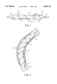
- FIG. 2 illustrates the dilatation balloon of FIG. 1 in place in a curved blood vessel showing how the dilatation balloon conforms to the shape of the blood vessel;
- FIG. 3 illustrates a dilatation catheter of the present invention having multiple helical grooves extending parallel to each other;
- FIG. 4 illustrates a dilatation balloon of the present invention incorporating criss-crossed helical grooves extending in opposite directions;
- FIGS. 5A and 5B illustrate a dilatation balloon of the present invention having a high degree of diametrical compliance
- FIG. 6 is a graph illustrating the relationship between pitch, width and depth of the helical groove, the number of helical grooves, and the degree of diametrical compliance imparted to the dilatation balloon;
- FIGS. 6A, 6B, 6C, 6D illustrate, in cross-section, the manner in which helical grooves provide diametrical compliance
- FIG. 7A and 7B illustrate dilatation balloons similar to FIGS. 1 and 5 except that the helical groove extends over only a portion of the dilating surface of the dilatation balloon.
- FIG. 1 illustrates a dilatation catheter 10 including a dilatation balloon 12 mounted on the distal end of a catheter shaft 14.
- a helical groove 16 extends the length of the balloon, preferably from a cone 18 to a cone 20. The groove 16 may extend into the cones 18 and 20.
- the helical groove 16 reduces the diameter of the dilatation balloon 12 in the grooved area and interrupts the diameter of a dilating surface 28 along the length of the balloon 12.
- the helical groove 16 is defined by a pitch, a width and a depth. The pitch refers to the longitudinal spacing 22 of the coils of the helical groove 16 in the dilating surface 28 of the dilatation balloon 12.
- the width refers to the distance 24 that the groove 16 interrupts the dilating surface 28.
- the depth 26 refers to how deeply the groove extends below the dilating surface 28 of the balloon 12.
- the helical groove 16 acts as a hinge, allowing the balloon 12 to bend and flex at any point along the length of the balloon regardless of inflation pressure. When dilating a lesion, the dilatation balloon 12 tends to conform to the natural curves of the blood vessel.
- FIG. 2 illustrates the dilatation balloon 12 of FIG. 1 in place in a curved blood vessel 32.
- the catheter has been advanced to a point where the balloon 12 has crossed a stenosis or lesion 30.
- the dilatation balloon 12 conforms to the shape of the blood vessel 32.
- the blood vessel 32 is also dilated with minimal straightening of the blood vessel due to the flexibility imparted by the helical groove 16.
- FIG. 3 illustrates multiple helical grooves in dilatation balloon 12.
- two grooves, 16, 16A are illustrated.
- the grooves extend generally parallel to each other in the same direction longitudinally in the dilating surface 28 of the balloon 12. Where the helical grooves are spaced closer together along the longitudinal direction of the catheter as in regions 34, the dilatation balloon 12 is more flexible than in the regions 36 where the grooves are spaced further apart.
- FIG. 4 illustrates a dilatation balloon 12 having multiple helical grooves wherein the multiple helical grooves 16, 16B extend generally opposite to one another in a criss-crossed fashion.
- the criss-crossed grooves help to reduce twisting of the dilatation balloon during inflation or deflation.
- the helical groove not only allows the balloon to bend and flex at any region of the balloon, but also permits blood to perfuse downstream of the balloon during dilatation.
- the dilatation time during an angioplasty procedure can be increased because blood flow is maintained during dilatation.
- the helical groove should extend into each end portion cone 18, 20 to allow blood to perfuse through groove 16 past dilatation balloon 12.
- the depth, width, and number of grooves may be increased.
- the present invention also overcomes the very significant problem of "winging” that occurs with most conventional dilatation balloons.
- Winging refers to the formation of undesirable flat folds (wings), which extend outward from the rest of the catheter.
- the helical groove permits the dilatation balloon 12 to deflate without winging.
- the helical groove resists the tendency of the balloon to flatten and instead the balloon folds down tightly along the catheter body, resulting in a lower deflated profile.
- This allows the dilatation balloon 12 to be placed or pass through a stenosis that may prevent passage of a conventional balloon.
- the tendency to reduce winging is characteristic of all embodiments of the invention.
- the helical groove may be used to impart diametrical compliance to the dilatation balloon 12.
- the balloon can be made to be diametrically compliant wherein the inflated diameter of the dilatation balloon is a linear function of the inflation pressure.
- This aspect of the present invention is particularly advantageous when the dilatation balloon is constructed from a material such as polyethylene terephthalate (PET) or various nylons. PET is widely used as a material for dilatation catheter balloons because, depending upon the particular balloon mold used, there is a predetermined maximum diameter that the inflated balloon will attain.
- PET polyethylene terephthalate
- a PET dilatation balloon becomes a "limited compliance balloon,” meaning that it has diametrical compliance until a predetermined maximum diameter is reached and further increases in inflation pressure do not increase the inflated balloon diameter.
- the concept of controlled compliance will be better understood with reference to FIG. 6.
- a number of small grooves disposed in a criss-crossed manner such as illustrated in FIG. 4 or in a parallel manner such as illustrated in FIG. 3 may be used to impart diametrical compliance or to construct a limited compliance balloon.
- the balloon when helical grooves such as illustrated in FIG. 5 are incorporated into a dilatation balloon constructed of substantially non-compliant material, such as PET, the balloon exhibits diametrical compliance up until a predetermined limiting or maximum diameter is reached. Inflation pressures above the level at which the limiting diameter is reached will not cause an increase in the diameter of the dilatation balloon.
- the dilatation balloon of the present invention has a linear diametrical compliance as illustrated by portions 50, 52, and 54 of respective curves 56, 58, and 60. Above a predetermined maximum diameter (points 62, 64, 66, respectively), increases in inflation pressure do not increase balloon diameter as illustrated by portions 68, 70, and 72 of curves 56, 58, and 60 respectively.
- any degree of diametrical compliance and any limiting diameter within the working range of the balloon material may be obtained by choosing the proper combination of pitch, depth, width of the groove and the number of grooves in the surface of the dilatation balloon.
- FIGS. 6A-6B illustrate how the helical grooves in the dilatation balloon 12 provide limited or controlled diametrical compliance.
- FIG. 6A illustrates, in cross-section, the dilatation balloon having a number of helical grooves 40 in the dilating surface 28.
- the dilatation balloon 12 is in an uninflated or low pressure state. As inflation pressure is increased, the helical grooves 40 begin to gradually disappear as illustrated in FIGS. 6B and 6C.
- FIG. 6D dilatation balloon 12 is fully inflated and further increases in inflation pressure do not increase the diameter of the dilatation balloon.
- FIGS. 6A-6C represent diametrical compliance along the portions 50, 52, and 54 of curves 56, 58, and 60, respectively.
- FIG. 6D represents the diameter of the dilatation balloon at points 62, 64, or 66 of curves 56, 58, and 60, respectively. Beyond these points, as illustrated in FIG. 6, an increase in inflation pressure does not substantially increase the diameter of the dilatation balloon.
- non-compliant PET or nylon balloon material perform like a compliant material, but with an upper limit on its size. This offers the clinical advantage of adjustable diameter without the risk of over-sizing or rupturing at high pressures.
- a helical groove in a non-compliant material has been described, but the invention is not so limited.
- a helical groove could also be used to further control diametrical compliance in a dilatation balloon constructed of compliant material.
- the helical groove provides another dimension of control and the resulting diametrical compliance is a function of both the chosen material and the groove design.
- the helical groove may be provided in only a portion of the dilating surface of the dilatation balloon. As illustrated in FIG. 7A, helical groove 16 extends only over portion 74 of the dilatation balloon 12. This single, relatively large helical groove allows the dilatation balloon 12 to conform to the shape of a circuitous blood vessel only in region 74.
- region 76 will provide a limited compliance type region whereas the remainder of the dilatation balloon 12 will provide essentially no diametrical compliance.
- Dilatation balloons may be provided with helical grooves in multiple portions of the balloon longitudinally separated from one another to create zones of conformance/compliance.
- a dilatation balloon can be constructed having zones that provide a combination of conformance and compliance depending upon overall catheter performance desired.
- dilatation balloons can be constructed to readily conform to curved blood vessels and perfuse blood past the dilatation balloon during dilation.
- a single helical groove at a 45° pitch angle may be used in a balloon having a maximum diameter of 3 mm.
- the groove may be one millimeter deep, have a radius of 0.5 mm at the bottom and provide a 60° included angle from the bottom of the groove to the dilation surface.
- a degree of diametrical compliance can be provided in a dilatation balloon constructed of a non-compliant material to provide a limited compliance dilatation balloon.
- a compliant balloon may be provided in a dilatation balloon having a maximum diameter of 3 mm by providing a number of helical grooves each having a 45° pitch angle. Each of the helical grooves is longitudinally separated from one another by approximately 0.005 inches. The grooves may be 0.005 inches wide by 0.005 inches deep. These grooves give the balloon a corrugated look. The grooves may be run in the opposite direction as well in a criss-crossed type fashion.
- these two features can be combined by choosing the pitch, width, and depth of the helical groove as well as the number of helical grooves to provide a dilatation balloon that has a combination of conformance capability and diametrical compliance with an upper limit to the balloon diameter.
- One particular advantage of the present invention is that it provides approximately 80% of the dilatation surface of a conventional straight dilatation balloon.
- prior art conforming type balloons such as those shown in U.S. Pat. No. 4,983,167 use discrete balloons spaced longitudinally adjacent on the catheter shaft or a single balloon having regions of restricted diameter alternating with regions capable of producing radial dilating forces. These types of balloons provide only approximately 30% of the dilating surface of a conventional straight dilatation balloon.
- the relatively low and non-continuous dilating surface of prior art balloons may not produce a smooth luminal surface when dilating a lesion or stenosis in a bend in the blood vessel.
- the present invention with its much higher total dilating surface tends to produce smoother and more uniform dilation of the blood vessel lumen.
- a helical groove in the dilatation surface of the dilatation balloon is the best way of achieving all of the advantages of the present invention.
- a helical groove provides uniform "hoop stress" around the perimeter of the fully inflated dilatation balloon.
- Hoop stress refers to the tangentially directed force created by the pressure and directed by the helical groove that maintains the circular cross-section of the balloon during inflation.
- the hoop stress controls the diameter of the dilatation balloon so that inflation pressure inside the balloon results in a uniform balloon diameter over the dilatation surface for any given inflation pressure.
- the invention thus provides perfusion of blood past the dilatation balloon and avoidance of straightening of the blood vessel when the dilatation balloon is inflated.
- the present invention allows diametrical compliance to be controlled and designed into the dilatation balloon. Another advantage is that the use of one or more helical grooves allows the dilatation balloon to be deflated without winging.
Abstract
Description
Claims (70)
Priority Applications (6)
| Application Number | Priority Date | Filing Date | Title |
|---|---|---|---|
| US08/171,061 US5545132A (en) | 1993-12-21 | 1993-12-21 | Helically grooved balloon for dilatation catheter and method of using |
| EP95905998A EP0735906B1 (en) | 1993-12-21 | 1994-12-21 | Helically grooved balloon for dilatation catheter |
| DE69430486T DE69430486T2 (en) | 1993-12-21 | 1994-12-21 | SCREW LINE GROOVED BALLOON FOR DILATATION CATHETER |
| JP7517533A JPH09506805A (en) | 1993-12-21 | 1994-12-21 | Balloon with spiral groove for use in expandable catheter |
| PCT/US1994/014604 WO1995017223A1 (en) | 1993-12-21 | 1994-12-21 | Helically grooved balloon for dilatation catheter |
| ES95905998T ES2176314T3 (en) | 1993-12-21 | 1994-12-21 | BALLOON WITH HELICOIDAL SLOTS FOR DILATATION CATHETER. |
Applications Claiming Priority (1)
| Application Number | Priority Date | Filing Date | Title |
|---|---|---|---|
| US08/171,061 US5545132A (en) | 1993-12-21 | 1993-12-21 | Helically grooved balloon for dilatation catheter and method of using |
Publications (1)
| Publication Number | Publication Date |
|---|---|
| US5545132A true US5545132A (en) | 1996-08-13 |
Family
ID=22622344
Family Applications (1)
| Application Number | Title | Priority Date | Filing Date |
|---|---|---|---|
| US08/171,061 Expired - Fee Related US5545132A (en) | 1993-12-21 | 1993-12-21 | Helically grooved balloon for dilatation catheter and method of using |
Country Status (6)
| Country | Link |
|---|---|
| US (1) | US5545132A (en) |
| EP (1) | EP0735906B1 (en) |
| JP (1) | JPH09506805A (en) |
| DE (1) | DE69430486T2 (en) |
| ES (1) | ES2176314T3 (en) |
| WO (1) | WO1995017223A1 (en) |
Cited By (166)
| Publication number | Priority date | Publication date | Assignee | Title |
|---|---|---|---|---|
| WO1997003716A1 (en) * | 1995-07-20 | 1997-02-06 | Navius Corporation | Distensible pet balloon and method of manufacture |
| US5797948A (en) * | 1996-10-03 | 1998-08-25 | Cordis Corporation | Centering balloon catheter |
| US5843050A (en) * | 1995-11-13 | 1998-12-01 | Micro Therapeutics, Inc. | Microcatheter |
| US5853389A (en) * | 1996-03-07 | 1998-12-29 | Cordis Corporation | Balloon catheter and method for manufacturing |
| US5855546A (en) * | 1996-02-29 | 1999-01-05 | Sci-Med Life Systems | Perfusion balloon and radioactive wire delivery system |
| US5865720A (en) * | 1997-03-06 | 1999-02-02 | Scimed Life Systems, Inc. | Expandable and retrievable radiation delivery system |
| US5873811A (en) * | 1997-01-10 | 1999-02-23 | Sci-Med Life Systems | Composition containing a radioactive component for treatment of vessel wall |
| US5882290A (en) * | 1996-02-29 | 1999-03-16 | Scimed Life Systems, Inc. | Intravascular radiation delivery system |
| US5910102A (en) * | 1997-01-10 | 1999-06-08 | Scimed Life Systems, Inc. | Conversion of beta radiation to gamma radiation for intravascular radiation therapy |
| US5913871A (en) * | 1996-09-25 | 1999-06-22 | Medtronic, Inc. | Balloon modification for improved stent fixation and deployment |
| US5951458A (en) * | 1996-02-29 | 1999-09-14 | Scimed Life Systems, Inc. | Local application of oxidizing agents to prevent restenosis |
| US5976155A (en) * | 1999-03-05 | 1999-11-02 | Advanced Cardiovascular Systems, Inc. | System for removably securing a stent on a catheter assembly and method of use |
| US6019718A (en) * | 1997-05-30 | 2000-02-01 | Scimed Life Systems, Inc. | Apparatus for intravascular radioactive treatment |
| US6048350A (en) * | 1999-06-14 | 2000-04-11 | Scimed Life Systems, Inc. | Segmented balloon delivery system |
| US6059713A (en) * | 1997-03-06 | 2000-05-09 | Scimed Life Systems, Inc. | Catheter system having tubular radiation source with movable guide wire |
| US6099454A (en) * | 1996-02-29 | 2000-08-08 | Scimed Life Systems, Inc. | Perfusion balloon and radioactive wire delivery system |
| US6110097A (en) * | 1997-03-06 | 2000-08-29 | Scimed Life Systems, Inc. | Perfusion balloon catheter with radioactive source |
| WO2000057815A1 (en) | 1999-03-31 | 2000-10-05 | Scimed Life Systems, Inc. | Stent security balloon catheter |
| US6129706A (en) * | 1998-12-10 | 2000-10-10 | Janacek; Jaroslav | Corrugated catheter balloon |
| US6264596B1 (en) | 1997-11-03 | 2001-07-24 | Meadox Medicals, Inc. | In-situ radioactive medical device |
| EP1009467A4 (en) * | 1997-02-19 | 2001-07-25 | Condado Med Devices Corp | Multi-purpose catheters, catheter systems, and radiation treatment |
| US6325826B1 (en) | 1998-01-14 | 2001-12-04 | Advanced Stent Technologies, Inc. | Extendible stent apparatus |
| US6432133B1 (en) | 1991-10-28 | 2002-08-13 | Advanced Cardiovascular Systems, Inc. | Expandable stents and method for making same |
| US6450988B1 (en) | 1999-12-29 | 2002-09-17 | Advanced Cardiovascular Systems, Inc. | Centering catheter with improved perfusion |
| US6468243B1 (en) * | 1999-08-25 | 2002-10-22 | Nipro Corporation | Balloon catheter |
| EP1256357A2 (en) * | 2001-05-08 | 2002-11-13 | Blue Medical Devices B.V. | Balloon catheter and method for manufacturing it |
| NL1018881C2 (en) * | 2001-05-08 | 2002-11-25 | Blue Medical Devices B V | Balloon catheter for dilating vessels and lumina comprise inflatable balloon with ends attached to it's catheter tube |
| US6522926B1 (en) | 2000-09-27 | 2003-02-18 | Cvrx, Inc. | Devices and methods for cardiovascular reflex control |
| US20030041047A1 (en) * | 2001-08-09 | 2003-02-27 | International Business Machines Corporation | Concept-based system for representing and processing multimedia objects with arbitrary constraints |
| US6527739B1 (en) | 2000-12-29 | 2003-03-04 | Advanced Cardiovascular Systems, Inc. | Spiraled balloon arrangement for treatment of a tortuous vessel |
| US20030060832A1 (en) * | 2001-09-26 | 2003-03-27 | Guinan Terry A. | Stent delivery catheter with grooved balloon and methods of making same |
| WO2003024362A1 (en) * | 2001-09-14 | 2003-03-27 | Scimed Life Systems, Inc. | Conformable balloons |
| US20030181923A1 (en) * | 1996-11-04 | 2003-09-25 | Gil Vardi | Methods for deploying stents in bifurcations |
| US20030191436A1 (en) * | 2002-04-05 | 2003-10-09 | Horvers Ronald Adrianus Maria | Balloon catheter |
| EP1352671A1 (en) * | 2002-04-08 | 2003-10-15 | Acrostak Corp. | PTCA and/or PTA balloon |
| US6652485B1 (en) | 2000-05-31 | 2003-11-25 | Advanced Cardiovascular Systems, Inc. | Balloon shoulder designs |
| EP1352672A3 (en) * | 2002-04-08 | 2004-01-07 | Acrostak Corp. | PTCA and/or PTA balloon |
| US6676590B1 (en) | 1997-03-06 | 2004-01-13 | Scimed Life Systems, Inc. | Catheter system having tubular radiation source |
| US6682536B2 (en) | 2000-03-22 | 2004-01-27 | Advanced Stent Technologies, Inc. | Guidewire introducer sheath |
| US6689156B1 (en) | 1999-09-23 | 2004-02-10 | Advanced Stent Technologies, Inc. | Stent range transducers and methods of use |
| US6692483B2 (en) | 1996-11-04 | 2004-02-17 | Advanced Stent Technologies, Inc. | Catheter with attached flexible side sheath |
| US20040059292A1 (en) * | 2002-06-26 | 2004-03-25 | Terumo Kabushiki Kaisha | Catheter and medical tube |
| US6716252B2 (en) | 2000-06-30 | 2004-04-06 | Wit Ip Corporation | Prostatic stent with localized tissue engaging anchoring means and methods for inhibiting obstruction of the prostatic urethra |
| US20040086674A1 (en) * | 2002-11-01 | 2004-05-06 | Holman Thomas J. | Laser sintering process and devices made therefrom |
| EP1417984A2 (en) * | 2002-11-08 | 2004-05-12 | Blue Medical Devices B.V. | Balloon catheter |
| US6736841B2 (en) | 1999-03-31 | 2004-05-18 | Scimed Life Systems, Inc. | Textured and/or marked balloon for stent delivery |
| US20040143287A1 (en) * | 2003-01-21 | 2004-07-22 | Angioscore, Inc. | Apparatus and methods for treating hardened vascular lesions |
| US20040215228A1 (en) * | 2003-04-28 | 2004-10-28 | Cardiac Pacemakers, Inc. | Compliant guiding catheter sheath system |
| US20040220607A1 (en) * | 2003-04-30 | 2004-11-04 | Donovan Maura G. | Method and systems for treating vulnerable plaque |
| US20040225318A1 (en) * | 2003-05-05 | 2004-11-11 | Tracee Eidenschink | Balloon catheter and method of making same |
| US20040230136A1 (en) * | 2003-05-14 | 2004-11-18 | Corrigan Richard F. | Guidewire having axially extending flow through passageways |
| US20040254616A1 (en) * | 2000-09-27 | 2004-12-16 | Cvrx, Inc. | Stimulus regimens for cardiovascular reflex control |
| US6835203B1 (en) | 1996-11-04 | 2004-12-28 | Advanced Stent Technologies, Inc. | Extendible stent apparatus |
| US20050021070A1 (en) * | 2003-01-21 | 2005-01-27 | Angioscore, Inc. | Methods and apparatus for manipulating vascular prostheses |
| US6850801B2 (en) | 2001-09-26 | 2005-02-01 | Cvrx, Inc. | Mapping methods for cardiovascular reflex control devices |
| US20050026462A1 (en) * | 2003-07-30 | 2005-02-03 | Theodis Johnson | Relative rotation signal transfer assembly |
| US6893430B2 (en) | 1998-02-04 | 2005-05-17 | Wit Ip Corporation | Urethral catheter and guide |
| US20050182361A1 (en) * | 1998-05-18 | 2005-08-18 | Boston Scientific Scimed, Inc. | Localized delivery of drug agents |
| US20050216047A1 (en) * | 2004-03-26 | 2005-09-29 | Terumo Kabushiki Kaisha | Catheter with expandable body and method of dilating a blood vessel with such catheter |
| WO2005094477A2 (en) | 2004-03-25 | 2005-10-13 | Angioscore, Inc. | Apparatus and methods for treating hardened vascular lesions |
| US6962602B2 (en) | 1996-11-04 | 2005-11-08 | Advanced Stent Tech Llc | Method for employing an extendible stent apparatus |
| US6985774B2 (en) | 2000-09-27 | 2006-01-10 | Cvrx, Inc. | Stimulus regimens for cardiovascular reflex control |
| US20060184112A1 (en) * | 2005-02-17 | 2006-08-17 | Horn Daniel J | Medical devices |
| WO2006088621A1 (en) * | 2005-02-11 | 2006-08-24 | Boston Scientific Limited | Cutting balloon catheter having increased flexibility regions |
| WO2006124398A2 (en) | 2005-05-11 | 2006-11-23 | Angioscore, Inc. | Methods and systems for delivering substances into luminal walls |
| US20060265051A1 (en) * | 2003-03-18 | 2006-11-23 | Veryan Medical Limited | Helical stent |
| US20060276820A1 (en) * | 2003-05-19 | 2006-12-07 | Youichi Yamaguchi | Balloon catheter and method of manufacturing the same |
| US7158832B2 (en) | 2000-09-27 | 2007-01-02 | Cvrx, Inc. | Electrode designs and methods of use for cardiovascular reflex control devices |
| US20070016278A1 (en) * | 2005-07-01 | 2007-01-18 | Shippy James L Iii | Medical devices |
| US20070016240A1 (en) * | 2005-06-17 | 2007-01-18 | Abbott Laboratories | Method of reducing rigidity of angioplasty balloon sections |
| US20070112407A1 (en) * | 2005-11-14 | 2007-05-17 | Boston Scientific Scimed, Inc. | Twisting bifurcation delivery system |
| US7220275B2 (en) | 1996-11-04 | 2007-05-22 | Advanced Stent Technologies, Inc. | Stent with protruding branch portion for bifurcated vessels |
| US20070156198A1 (en) * | 2004-06-30 | 2007-07-05 | Cvrx, Inc. | Coordinated therapy for disordered breathing including baroreflex modulation |
| US7344557B2 (en) | 2003-11-12 | 2008-03-18 | Advanced Stent Technologies, Inc. | Catheter balloon systems and methods |
| US20080114294A1 (en) * | 2006-11-14 | 2008-05-15 | Holman Thomas J | Medical balloon deflation |
| US20080167699A1 (en) * | 2000-09-27 | 2008-07-10 | Cvrx, Inc. | Method and Apparatus for Providing Complex Tissue Stimulation Parameters |
| US20080306440A1 (en) * | 2007-03-27 | 2008-12-11 | Eran Hirszowicz | Spiral balloon catheter |
| US20090227949A1 (en) * | 2008-03-06 | 2009-09-10 | Boston Scientific Scimed, Inc. | Balloon catheter devices with folded balloons |
| US7616997B2 (en) | 2000-09-27 | 2009-11-10 | Kieval Robert S | Devices and methods for cardiovascular reflex control via coupled electrodes |
| WO2009155141A2 (en) * | 2008-06-18 | 2009-12-23 | John Isham | Rectal balloon apparatus with radiation sensor and/or markers |
| US20100022976A1 (en) * | 2007-02-22 | 2010-01-28 | Convatec Technologies Inc. | Seal for a rectal or ostomy appliance |
| US7655030B2 (en) | 2003-07-18 | 2010-02-02 | Boston Scientific Scimed, Inc. | Catheter balloon systems and methods |
| US20100049292A1 (en) * | 2008-05-06 | 2010-02-25 | The Cleveland Clinic Foundation | Balloon for a body lumen and method of use |
| US20100087906A1 (en) * | 2005-06-16 | 2010-04-08 | Angiomed Gmbh & Co. Medizintechnik Ag | Catheter Device |
| US20100094403A1 (en) * | 2008-10-10 | 2010-04-15 | Kevin Heraty | Medical device |
| US20100145309A1 (en) * | 2008-12-03 | 2010-06-10 | C. R. Bard, Inc. | Retractable catheter |
| US7753950B2 (en) | 1997-08-13 | 2010-07-13 | Advanced Cardiovascular Systems, Inc. | Stent and catheter assembly and method for treating bifurcations |
| US7763198B2 (en) | 2005-04-12 | 2010-07-27 | Abbott Cardiovascular Systems Inc. | Method for retaining a vascular stent on a catheter |
| US7766955B2 (en) | 1996-11-04 | 2010-08-03 | Boston Scientific Scimed, Inc. | Extendible stent apparatus |
| US7813812B2 (en) | 2000-09-27 | 2010-10-12 | Cvrx, Inc. | Baroreflex stimulator with integrated pressure sensor |
| US20100286756A1 (en) * | 2005-06-16 | 2010-11-11 | C.R. Bard Inc. | Catheter Device |
| US7840271B2 (en) | 2000-09-27 | 2010-11-23 | Cvrx, Inc. | Stimulus regimens for cardiovascular reflex control |
| US20100331876A1 (en) * | 2008-09-02 | 2010-12-30 | Cedeno Jose Herrera | Method and a catheter device for the dynamic regulation of the venous return to the heart for the treatment of patients with heart failure |
| US20110054396A1 (en) * | 2009-08-27 | 2011-03-03 | Boston Scientific Scimed, Inc. | Balloon Catheter Devices With Drug-Coated Sheath |
| US7947207B2 (en) | 2005-04-12 | 2011-05-24 | Abbott Cardiovascular Systems Inc. | Method for retaining a vascular stent on a catheter |
| US7950393B2 (en) | 2006-09-29 | 2011-05-31 | Nellcor Puritan Bennett Llc | Endotracheal cuff and technique for using the same |
| EP2335768A2 (en) * | 2008-09-02 | 2011-06-22 | José Herrera Cedeño | Inflatable balloon catheter device and method for dynamic regulation of venous return |
| US20110230946A1 (en) * | 2010-03-16 | 2011-09-22 | Abbott Laboratories | Easy marker placement balloon mold |
| US8086314B1 (en) | 2000-09-27 | 2011-12-27 | Cvrx, Inc. | Devices and methods for cardiovascular reflex control |
| US20120022501A1 (en) * | 2006-06-05 | 2012-01-26 | Twincath, Llc | Multi-lumen catheter with protected tip |
| US8109879B2 (en) | 2006-01-10 | 2012-02-07 | Cardiac Pacemakers, Inc. | Assessing autonomic activity using baroreflex analysis |
| US20120053613A1 (en) * | 2007-04-05 | 2012-03-01 | Barry Weitzner | Gastric Filler Devices for Obesity Therapy |
| WO2011140456A3 (en) * | 2010-05-07 | 2012-04-05 | Carefusion 2200, Inc. | Improved catheter design for use in treating pleural diseases |
| US8196584B2 (en) | 2006-06-22 | 2012-06-12 | Nellcor Puritan Bennett Llc | Endotracheal cuff and technique for using the same |
| US8211167B2 (en) | 1999-12-06 | 2012-07-03 | Boston Scientific Scimed, Inc. | Method of using a catheter with attached flexible side sheath |
| US8216209B2 (en) | 2007-05-31 | 2012-07-10 | Abbott Cardiovascular Systems Inc. | Method and apparatus for delivering an agent to a kidney |
| US8224437B2 (en) | 2003-10-22 | 2012-07-17 | Cvrx, Inc. | Baroreflex activation for sedation and sleep |
| US8249705B1 (en) | 2007-03-20 | 2012-08-21 | Cvrx, Inc. | Devices, systems, and methods for improving left ventricular structure and function using baroreflex activation therapy |
| US8298280B2 (en) | 2003-08-21 | 2012-10-30 | Boston Scientific Scimed, Inc. | Stent with protruding branch portion for bifurcated vessels |
| US8307830B2 (en) | 2006-09-29 | 2012-11-13 | Nellcor Puritan Bennett Llc | Endotracheal cuff and technique for using the same |
| US8377108B2 (en) | 2008-06-02 | 2013-02-19 | Boston Scientific Scimed, Inc. | Staggered two balloon bifurcation catheter assembly and methods |
| US8413659B2 (en) | 2006-09-29 | 2013-04-09 | Covidien Lp | Self-sizing adjustable endotracheal tube |
| US20130110042A1 (en) * | 2008-05-12 | 2013-05-02 | Mayo Foundation For Medical Education And Research | Hemostatic Devices and Methods for Use Thereof |
| US8434487B2 (en) | 2006-06-22 | 2013-05-07 | Covidien Lp | Endotracheal cuff and technique for using the same |
| US8475518B2 (en) | 2003-12-22 | 2013-07-02 | Advanced Cardiovascular Systems, Inc. | Stent with anchors to prevent vulnerable plaque rupture during deployment |
| US8486134B2 (en) | 2007-08-01 | 2013-07-16 | Boston Scientific Scimed, Inc. | Bifurcation treatment system and methods |
| US8561614B2 (en) | 2006-09-28 | 2013-10-22 | Covidien Lp | Multi-layer cuffs for medical devices |
| US8590534B2 (en) | 2009-06-22 | 2013-11-26 | Covidien Lp | Cuff for use with medical tubing and method and apparatus for making the same |
| US8594794B2 (en) | 2007-07-24 | 2013-11-26 | Cvrx, Inc. | Baroreflex activation therapy with incrementally changing intensity |
| US8617231B2 (en) | 2001-05-18 | 2013-12-31 | Boston Scientific Scimed, Inc. | Dual guidewire exchange catheter system |
| US8684175B2 (en) | 2006-09-22 | 2014-04-01 | Covidien Lp | Method for shipping and protecting an endotracheal tube with an inflated cuff |
| US8708955B2 (en) | 2008-06-02 | 2014-04-29 | Loma Vista Medical, Inc. | Inflatable medical devices |
| US8747456B2 (en) | 2007-12-31 | 2014-06-10 | Boston Scientific Scimed, Inc. | Bifurcation stent delivery system and methods |
| US8750978B2 (en) | 2007-12-31 | 2014-06-10 | Covidien Lp | System and sensor for early detection of shock or perfusion failure and technique for using the same |
| US8807136B2 (en) | 2006-09-29 | 2014-08-19 | Covidien Lp | Self-sizing adjustable endotracheal tube |
| US8813750B2 (en) | 2006-09-29 | 2014-08-26 | Covidien Lp | Self-sizing adjustable endotracheal tube |
| US8821561B2 (en) | 2006-02-22 | 2014-09-02 | Boston Scientific Scimed, Inc. | Marker arrangement for bifurcation catheter |
| US8827954B2 (en) | 2008-06-05 | 2014-09-09 | Boston Scientific Scimed, Inc. | Deflatable bifurcated device |
| US8936567B2 (en) | 2007-11-14 | 2015-01-20 | Boston Scientific Scimed, Inc. | Balloon bifurcated lumen treatment |
| US20150209556A1 (en) * | 2014-01-30 | 2015-07-30 | Chuter A.M. Timothy | Flexible high-pressure angioplasty balloons |
| US9125667B2 (en) | 2004-09-10 | 2015-09-08 | Vessix Vascular, Inc. | System for inducing desirable temperature effects on body tissue |
| US9144509B2 (en) | 2007-05-31 | 2015-09-29 | Abbott Cardiovascular Systems Inc. | Method and apparatus for delivering an agent to a kidney |
| US9149610B2 (en) | 2007-05-31 | 2015-10-06 | Abbott Cardiovascular Systems Inc. | Method and apparatus for improving delivery of an agent to a kidney |
| US20150283360A1 (en) * | 2013-04-05 | 2015-10-08 | Sanford Health | Drug Delivery Balloon Apparatus and Methods for Use |
| US9173977B2 (en) | 2010-04-19 | 2015-11-03 | Angioscore, Inc. | Coating formulations for scoring or cutting balloon catheters |
| US20150367112A1 (en) * | 2014-06-20 | 2015-12-24 | Daniel Gelbart | Medical Balloon with Reduced Straightening Force |
| US9351756B2 (en) | 2010-09-21 | 2016-05-31 | Angioscore, Inc. | Method and system for treating valve stenosis |
| US9364586B2 (en) | 2007-05-31 | 2016-06-14 | Abbott Cardiovascular Systems Inc. | Method and apparatus for improving delivery of an agent to a kidney |
| US9375328B2 (en) | 2001-11-09 | 2016-06-28 | Angioscore, Inc. | Balloon catheter with non-deployable stent |
| CN106310499A (en) * | 2015-06-15 | 2017-01-11 | 易生科技(北京)有限公司 | Balloon dilatation catheter, bent balloon and manufacturing method thereof, and bent balloon forming mold |
| US9572694B2 (en) | 2003-03-18 | 2017-02-21 | Veryan Medical Limited | Helical graft |
| US9592119B2 (en) | 2010-07-13 | 2017-03-14 | C.R. Bard, Inc. | Inflatable medical devices |
| US9649156B2 (en) | 2010-12-15 | 2017-05-16 | Boston Scientific Scimed, Inc. | Bipolar off-wall electrode device for renal nerve ablation |
| US9669194B2 (en) | 2013-03-14 | 2017-06-06 | W. L. Gore & Associates, Inc. | Conformable balloon devices and methods |
| US9724121B2 (en) | 2014-02-02 | 2017-08-08 | TriReme Medical, LLC | Apparatus and methods for recannalization, valve repair and replacement |
| US9730726B2 (en) | 2011-10-07 | 2017-08-15 | W. L. Gore & Associates, Inc. | Balloon assemblies having controllably variable topographies |
| US9848946B2 (en) | 2010-11-15 | 2017-12-26 | Boston Scientific Scimed, Inc. | Self-expanding cooling electrode for renal nerve ablation |
| US20180014879A1 (en) * | 2014-12-23 | 2018-01-18 | Mark Steven Whiteley | Medical device for treating a vein |
| US9907609B2 (en) | 2014-02-04 | 2018-03-06 | Boston Scientific Scimed, Inc. | Alternative placement of thermal sensors on bipolar electrode |
| US20180200483A1 (en) * | 2016-02-17 | 2018-07-19 | Project Moray, Inc. | Local contraction of flexible bodies using balloon expansion for extension-contraction catheter articulation and other uses |
| US20180235743A1 (en) * | 2017-02-23 | 2018-08-23 | Boston Scientific Scimed, Inc. | Medical drain device |
| US10086178B2 (en) | 2001-11-09 | 2018-10-02 | Angioscore, Inc. | Balloon catheter with non-deployable stent |
| US10117668B2 (en) | 2013-10-08 | 2018-11-06 | The Spectranetics Corporation | Balloon catheter with non-deployable stent having improved stability |
| US10130465B2 (en) | 2016-02-23 | 2018-11-20 | Abbott Cardiovascular Systems Inc. | Bifurcated tubular graft for treating tricuspid regurgitation |
| US10188436B2 (en) | 2010-11-09 | 2019-01-29 | Loma Vista Medical, Inc. | Inflatable medical devices |
| US10188273B2 (en) | 2007-01-30 | 2019-01-29 | Loma Vista Medical, Inc. | Biological navigation device |
| US10307975B2 (en) * | 2015-07-17 | 2019-06-04 | Rohr, Inc. | Resin-infusion process for composites manufacturing |
| US10426483B2 (en) | 2008-05-12 | 2019-10-01 | Mitchell R. Humphreys | Hemostatic devices and methods for use thereof |
| US20190298518A1 (en) * | 2011-02-11 | 2019-10-03 | Edwards Lifesciences Corporation | Stability device for use with percutaneous delivery systems |
| US10575973B2 (en) | 2018-04-11 | 2020-03-03 | Abbott Cardiovascular Systems Inc. | Intravascular stent having high fatigue performance |
| CN111298274A (en) * | 2020-05-14 | 2020-06-19 | 上海脉全医疗器械有限公司 | Medicine balloon and using method thereof |
| CN112439122A (en) * | 2019-09-05 | 2021-03-05 | 尤东侠 | Balloon dilatation catheter |
| US11000679B2 (en) | 2014-02-04 | 2021-05-11 | Boston Scientific Scimed, Inc. | Balloon protection and rewrapping devices and related methods of use |
| US11202671B2 (en) | 2014-01-06 | 2021-12-21 | Boston Scientific Scimed, Inc. | Tear resistant flex circuit assembly |
| WO2023057057A1 (en) * | 2021-10-06 | 2023-04-13 | Clearstream Technologies Limited | A catheter system for forming a fistula |
| US11850385B2 (en) | 2020-04-03 | 2023-12-26 | Covidien Lp | Balloon catheter |
Families Citing this family (14)
| Publication number | Priority date | Publication date | Assignee | Title |
|---|---|---|---|---|
| US6875197B1 (en) * | 2000-11-14 | 2005-04-05 | Advanced Cardiovascular Systems, Inc. | Dimensionally stable and growth controlled inflatable member for a catheter |
| JP2003310762A (en) * | 2002-02-19 | 2003-11-05 | Kawasumi Lab Inc | Balloon adaptor and balloon catheter with the same |
| US8556851B2 (en) | 2005-07-05 | 2013-10-15 | Angioslide Ltd. | Balloon catheter |
| US9439662B2 (en) | 2005-07-05 | 2016-09-13 | Angioslide Ltd. | Balloon catheter |
| MX2009003994A (en) * | 2006-10-17 | 2009-05-25 | Bard Inc C R | Waste management system. |
| US9622888B2 (en) | 2006-11-16 | 2017-04-18 | W. L. Gore & Associates, Inc. | Stent having flexibly connected adjacent stent elements |
| US8926688B2 (en) | 2008-01-11 | 2015-01-06 | W. L. Gore & Assoc. Inc. | Stent having adjacent elements connected by flexible webs |
| JP2011526530A (en) * | 2008-07-02 | 2011-10-13 | アンジオスライド リミテッド | Bellows type balloon catheter system and method of use thereof |
| US10688278B2 (en) * | 2009-11-30 | 2020-06-23 | Biosense Webster (Israel), Ltd. | Catheter with pressure measuring tip |
| WO2011089599A1 (en) | 2010-01-19 | 2011-07-28 | Angioslide Ltd. | Balloon catheter system and methods of making and use thereof |
| DE102012001188A1 (en) * | 2012-01-24 | 2013-07-25 | Qualimed Innovative Medizinprodukte Gmbh | balloon catheter |
| CN105025968A (en) | 2012-12-04 | 2015-11-04 | 安乔斯里德公司 | Balloon catheter and methods of use thereof |
| US10299948B2 (en) | 2014-11-26 | 2019-05-28 | W. L. Gore & Associates, Inc. | Balloon expandable endoprosthesis |
| US10568752B2 (en) | 2016-05-25 | 2020-02-25 | W. L. Gore & Associates, Inc. | Controlled endoprosthesis balloon expansion |
Citations (7)
| Publication number | Priority date | Publication date | Assignee | Title |
|---|---|---|---|---|
| US4950232A (en) * | 1987-08-11 | 1990-08-21 | Surelab Superior Research Laboratories | Cerebrospinal fluid shunt system |
| WO1993017748A1 (en) * | 1992-03-13 | 1993-09-16 | Medtronic, Inc. | Autoperfusion dilatation catheter |
| US5250070A (en) * | 1991-05-28 | 1993-10-05 | Parodi Juan C | Less traumatic angioplasty balloon for arterial dilatation |
| US5295995A (en) * | 1992-08-27 | 1994-03-22 | Kleiman Jay H | Perfusion dilatation catheter |
| US5306246A (en) * | 1990-11-09 | 1994-04-26 | Boston Scientific Corporation | Balloon for medical catheter |
| US5308356A (en) * | 1993-02-25 | 1994-05-03 | Blackshear Jr Perry L | Passive perfusion angioplasty catheter |
| US5348538A (en) * | 1992-09-29 | 1994-09-20 | Scimed Life Systems, Inc. | Shrinking balloon catheter having nonlinear or hybrid compliance curve |
Family Cites Families (2)
| Publication number | Priority date | Publication date | Assignee | Title |
|---|---|---|---|---|
| US4983167A (en) * | 1988-11-23 | 1991-01-08 | Harvinder Sahota | Balloon catheters |
| US4941877A (en) * | 1989-01-26 | 1990-07-17 | Cordis Corporation | Balloon catheter |
-
1993
- 1993-12-21 US US08/171,061 patent/US5545132A/en not_active Expired - Fee Related
-
1994
- 1994-12-21 DE DE69430486T patent/DE69430486T2/en not_active Expired - Fee Related
- 1994-12-21 WO PCT/US1994/014604 patent/WO1995017223A1/en active IP Right Grant
- 1994-12-21 JP JP7517533A patent/JPH09506805A/en not_active Ceased
- 1994-12-21 EP EP95905998A patent/EP0735906B1/en not_active Expired - Lifetime
- 1994-12-21 ES ES95905998T patent/ES2176314T3/en not_active Expired - Lifetime
Patent Citations (9)
| Publication number | Priority date | Publication date | Assignee | Title |
|---|---|---|---|---|
| US4950232A (en) * | 1987-08-11 | 1990-08-21 | Surelab Superior Research Laboratories | Cerebrospinal fluid shunt system |
| US5306246A (en) * | 1990-11-09 | 1994-04-26 | Boston Scientific Corporation | Balloon for medical catheter |
| US5250070A (en) * | 1991-05-28 | 1993-10-05 | Parodi Juan C | Less traumatic angioplasty balloon for arterial dilatation |
| WO1993017748A1 (en) * | 1992-03-13 | 1993-09-16 | Medtronic, Inc. | Autoperfusion dilatation catheter |
| US5295959A (en) * | 1992-03-13 | 1994-03-22 | Medtronic, Inc. | Autoperfusion dilatation catheter having a bonded channel |
| US5295995A (en) * | 1992-08-27 | 1994-03-22 | Kleiman Jay H | Perfusion dilatation catheter |
| US5348538A (en) * | 1992-09-29 | 1994-09-20 | Scimed Life Systems, Inc. | Shrinking balloon catheter having nonlinear or hybrid compliance curve |
| US5403340A (en) * | 1992-09-29 | 1995-04-04 | Scimed Lifesystems Inc. | Shrinking balloon catheter having nonlinear compliance curve |
| US5308356A (en) * | 1993-02-25 | 1994-05-03 | Blackshear Jr Perry L | Passive perfusion angioplasty catheter |
Cited By (325)
| Publication number | Priority date | Publication date | Assignee | Title |
|---|---|---|---|---|
| US6620193B1 (en) | 1991-10-28 | 2003-09-16 | Advanced Cardiovascular Systems, Inc. | Method of deploying a stent in a body lumen |
| US6432133B1 (en) | 1991-10-28 | 2002-08-13 | Advanced Cardiovascular Systems, Inc. | Expandable stents and method for making same |
| US6626933B1 (en) | 1991-10-28 | 2003-09-30 | Advanced Cardiovascular Systems, Inc. | Expandable stents and method for making same stent delivery system |
| US6689159B2 (en) | 1991-10-28 | 2004-02-10 | Advanced Cardiovascular Systems, Inc. | Expandable stents and method for making same |
| US6629991B1 (en) | 1991-10-28 | 2003-10-07 | Advanced Cardiovascular Systems, Inc. | Expandable stents and method for making same |
| US6596022B2 (en) | 1991-10-28 | 2003-07-22 | Advanced Cardiovascular Systems, Inc. | Expandable stents and method for making same |
| WO1997003716A1 (en) * | 1995-07-20 | 1997-02-06 | Navius Corporation | Distensible pet balloon and method of manufacture |
| US5843050A (en) * | 1995-11-13 | 1998-12-01 | Micro Therapeutics, Inc. | Microcatheter |
| US6306124B1 (en) | 1995-11-13 | 2001-10-23 | Micro Therapeutics, Inc. | Microcatheter |
| US6254588B1 (en) | 1995-11-13 | 2001-07-03 | Micro Therapeutics, Inc. | Microcatheter |
| US5882290A (en) * | 1996-02-29 | 1999-03-16 | Scimed Life Systems, Inc. | Intravascular radiation delivery system |
| US5855546A (en) * | 1996-02-29 | 1999-01-05 | Sci-Med Life Systems | Perfusion balloon and radioactive wire delivery system |
| US5951458A (en) * | 1996-02-29 | 1999-09-14 | Scimed Life Systems, Inc. | Local application of oxidizing agents to prevent restenosis |
| US6099454A (en) * | 1996-02-29 | 2000-08-08 | Scimed Life Systems, Inc. | Perfusion balloon and radioactive wire delivery system |
| US6398708B1 (en) | 1996-02-29 | 2002-06-04 | Scimed Life Systems, Inc. | Perfusion balloon and radioactive wire delivery system |
| US5853389A (en) * | 1996-03-07 | 1998-12-29 | Cordis Corporation | Balloon catheter and method for manufacturing |
| US5913871A (en) * | 1996-09-25 | 1999-06-22 | Medtronic, Inc. | Balloon modification for improved stent fixation and deployment |
| US6056906A (en) * | 1996-09-25 | 2000-05-02 | Medtronic, Inc. | Method of making an intervascular catheter system for implanting a radially expandable stent within a body vessel |
| US5797948A (en) * | 1996-10-03 | 1998-08-25 | Cordis Corporation | Centering balloon catheter |
| US6835203B1 (en) | 1996-11-04 | 2004-12-28 | Advanced Stent Technologies, Inc. | Extendible stent apparatus |
| US7766955B2 (en) | 1996-11-04 | 2010-08-03 | Boston Scientific Scimed, Inc. | Extendible stent apparatus |
| US7220275B2 (en) | 1996-11-04 | 2007-05-22 | Advanced Stent Technologies, Inc. | Stent with protruding branch portion for bifurcated vessels |
| US8771342B2 (en) | 1996-11-04 | 2014-07-08 | Boston Scientific Scimed, Inc. | Methods for deploying stents in bifurcations |
| US20030181923A1 (en) * | 1996-11-04 | 2003-09-25 | Gil Vardi | Methods for deploying stents in bifurcations |
| US6692483B2 (en) | 1996-11-04 | 2004-02-17 | Advanced Stent Technologies, Inc. | Catheter with attached flexible side sheath |
| US7678142B2 (en) | 1996-11-04 | 2010-03-16 | Boston Scientific Scimed, Inc. | Extendible stent apparatus |
| US6962602B2 (en) | 1996-11-04 | 2005-11-08 | Advanced Stent Tech Llc | Method for employing an extendible stent apparatus |
| US9561126B2 (en) | 1996-11-04 | 2017-02-07 | Boston Scientific Scimed, Inc. | Catheter with attached flexible side sheath |
| US7850725B2 (en) | 1996-11-04 | 2010-12-14 | Boston Scientific Scimed, Inc. | Extendible stent apparatus |
| US5873811A (en) * | 1997-01-10 | 1999-02-23 | Sci-Med Life Systems | Composition containing a radioactive component for treatment of vessel wall |
| US5910102A (en) * | 1997-01-10 | 1999-06-08 | Scimed Life Systems, Inc. | Conversion of beta radiation to gamma radiation for intravascular radiation therapy |
| EP1009467A4 (en) * | 1997-02-19 | 2001-07-25 | Condado Med Devices Corp | Multi-purpose catheters, catheter systems, and radiation treatment |
| US6117065A (en) * | 1997-03-06 | 2000-09-12 | Scimed Life Systems, Inc. | Perfusion balloon catheter with radioactive source |
| US5865720A (en) * | 1997-03-06 | 1999-02-02 | Scimed Life Systems, Inc. | Expandable and retrievable radiation delivery system |
| US6059713A (en) * | 1997-03-06 | 2000-05-09 | Scimed Life Systems, Inc. | Catheter system having tubular radiation source with movable guide wire |
| US6110097A (en) * | 1997-03-06 | 2000-08-29 | Scimed Life Systems, Inc. | Perfusion balloon catheter with radioactive source |
| US6676590B1 (en) | 1997-03-06 | 2004-01-13 | Scimed Life Systems, Inc. | Catheter system having tubular radiation source |
| US6422989B1 (en) | 1997-05-30 | 2002-07-23 | Scimed Life Systems, Inc. | Method for intravascular radioactive treatment |
| US6019718A (en) * | 1997-05-30 | 2000-02-01 | Scimed Life Systems, Inc. | Apparatus for intravascular radioactive treatment |
| US7753950B2 (en) | 1997-08-13 | 2010-07-13 | Advanced Cardiovascular Systems, Inc. | Stent and catheter assembly and method for treating bifurcations |
| US7955379B2 (en) | 1997-08-13 | 2011-06-07 | Abbott Cardiovascular Systems Inc. | Stent and catheter assembly and method for treating bifurcations |
| US6264596B1 (en) | 1997-11-03 | 2001-07-24 | Meadox Medicals, Inc. | In-situ radioactive medical device |
| US6706062B2 (en) | 1998-01-14 | 2004-03-16 | Advanced Stent Technologies, Inc. | Extendible stent apparatus |
| US6325826B1 (en) | 1998-01-14 | 2001-12-04 | Advanced Stent Technologies, Inc. | Extendible stent apparatus |
| US8241349B2 (en) | 1998-01-14 | 2012-08-14 | Boston Scientific Scimed, Inc. | Extendible stent apparatus |
| US7892279B2 (en) | 1998-01-14 | 2011-02-22 | Boston Scientific Scimed, Inc. | Extendible stent apparatus |
| US7537609B2 (en) | 1998-01-14 | 2009-05-26 | Boston Scientific Scimed, Inc. | Extendible stent apparatus |
| US7118593B2 (en) | 1998-01-14 | 2006-10-10 | Advanced Stent Technologies, Inc. | Extendible stent apparatus |
| US20050165383A1 (en) * | 1998-02-04 | 2005-07-28 | Uzi Eshel | Urethral catheter and guide |
| US6893430B2 (en) | 1998-02-04 | 2005-05-17 | Wit Ip Corporation | Urethral catheter and guide |
| US8574191B2 (en) | 1998-05-18 | 2013-11-05 | Boston Scientific Scimed, Inc. | Localized delivery of drug agents |
| US8262613B2 (en) | 1998-05-18 | 2012-09-11 | Boston Scientific Scimed, Inc. | Localized delivery of drug agents |
| US20050182361A1 (en) * | 1998-05-18 | 2005-08-18 | Boston Scientific Scimed, Inc. | Localized delivery of drug agents |
| US8177743B2 (en) | 1998-05-18 | 2012-05-15 | Boston Scientific Scimed, Inc. | Localized delivery of drug agents |
| US6129706A (en) * | 1998-12-10 | 2000-10-10 | Janacek; Jaroslav | Corrugated catheter balloon |
| US5976155A (en) * | 1999-03-05 | 1999-11-02 | Advanced Cardiovascular Systems, Inc. | System for removably securing a stent on a catheter assembly and method of use |
| US20030114915A1 (en) * | 1999-03-31 | 2003-06-19 | Wayne Mareiro | Stent security balloon/balloon catheter |
| US6676667B2 (en) | 1999-03-31 | 2004-01-13 | Scimed Life Systems, Inc. | Stent security balloon/balloon catheter |
| US6786889B1 (en) | 1999-03-31 | 2004-09-07 | Scimed Life Systems, Inc | Textured and/or marked balloon for stent delivery |
| US7056323B2 (en) | 1999-03-31 | 2006-06-06 | Scimed Life Systems, Inc. | Stent security balloon/balloon catheter |
| US6258099B1 (en) | 1999-03-31 | 2001-07-10 | Scimed Life Systems, Inc. | Stent security balloon/balloon catheter |
| WO2000057815A1 (en) | 1999-03-31 | 2000-10-05 | Scimed Life Systems, Inc. | Stent security balloon catheter |
| US6736841B2 (en) | 1999-03-31 | 2004-05-18 | Scimed Life Systems, Inc. | Textured and/or marked balloon for stent delivery |
| US7771462B1 (en) | 1999-06-04 | 2010-08-10 | Boston Scientific Scimed, Inc. | Catheter with side sheath and methods |
| US6048350A (en) * | 1999-06-14 | 2000-04-11 | Scimed Life Systems, Inc. | Segmented balloon delivery system |
| US6530948B1 (en) | 1999-06-14 | 2003-03-11 | Scimed Life Systems, Inc. | Segmented balloon delivery system |
| US6468243B1 (en) * | 1999-08-25 | 2002-10-22 | Nipro Corporation | Balloon catheter |
| US6689156B1 (en) | 1999-09-23 | 2004-02-10 | Advanced Stent Technologies, Inc. | Stent range transducers and methods of use |
| US7585317B2 (en) | 1999-09-23 | 2009-09-08 | Boston Scientific Scimed, Inc. | Stent range transducers |
| US8211167B2 (en) | 1999-12-06 | 2012-07-03 | Boston Scientific Scimed, Inc. | Method of using a catheter with attached flexible side sheath |
| US6450988B1 (en) | 1999-12-29 | 2002-09-17 | Advanced Cardiovascular Systems, Inc. | Centering catheter with improved perfusion |
| US6682536B2 (en) | 2000-03-22 | 2004-01-27 | Advanced Stent Technologies, Inc. | Guidewire introducer sheath |
| US6652485B1 (en) | 2000-05-31 | 2003-11-25 | Advanced Cardiovascular Systems, Inc. | Balloon shoulder designs |
| US6716252B2 (en) | 2000-06-30 | 2004-04-06 | Wit Ip Corporation | Prostatic stent with localized tissue engaging anchoring means and methods for inhibiting obstruction of the prostatic urethra |
| US7158832B2 (en) | 2000-09-27 | 2007-01-02 | Cvrx, Inc. | Electrode designs and methods of use for cardiovascular reflex control devices |
| US7813812B2 (en) | 2000-09-27 | 2010-10-12 | Cvrx, Inc. | Baroreflex stimulator with integrated pressure sensor |
| US20040254616A1 (en) * | 2000-09-27 | 2004-12-16 | Cvrx, Inc. | Stimulus regimens for cardiovascular reflex control |
| US7623926B2 (en) | 2000-09-27 | 2009-11-24 | Cvrx, Inc. | Stimulus regimens for cardiovascular reflex control |
| US8583236B2 (en) | 2000-09-27 | 2013-11-12 | Cvrx, Inc. | Devices and methods for cardiovascular reflex control |
| US9427583B2 (en) | 2000-09-27 | 2016-08-30 | Cvrx, Inc. | Electrode structures and methods for their use in cardiovascular reflex control |
| US9044609B2 (en) | 2000-09-27 | 2015-06-02 | Cvrx, Inc. | Electrode structures and methods for their use in cardiovascular reflex control |
| US20080167699A1 (en) * | 2000-09-27 | 2008-07-10 | Cvrx, Inc. | Method and Apparatus for Providing Complex Tissue Stimulation Parameters |
| US8606359B2 (en) | 2000-09-27 | 2013-12-10 | Cvrx, Inc. | System and method for sustained baroreflex stimulation |
| US7616997B2 (en) | 2000-09-27 | 2009-11-10 | Kieval Robert S | Devices and methods for cardiovascular reflex control via coupled electrodes |
| US7801614B2 (en) | 2000-09-27 | 2010-09-21 | Cvrx, Inc. | Stimulus regimens for cardiovascular reflex control |
| US8290595B2 (en) | 2000-09-27 | 2012-10-16 | Cvrx, Inc. | Method and apparatus for stimulation of baroreceptors in pulmonary artery |
| US8712531B2 (en) | 2000-09-27 | 2014-04-29 | Cvrx, Inc. | Automatic baroreflex modulation responsive to adverse event |
| US7840271B2 (en) | 2000-09-27 | 2010-11-23 | Cvrx, Inc. | Stimulus regimens for cardiovascular reflex control |
| US6985774B2 (en) | 2000-09-27 | 2006-01-10 | Cvrx, Inc. | Stimulus regimens for cardiovascular reflex control |
| US8880190B2 (en) | 2000-09-27 | 2014-11-04 | Cvrx, Inc. | Electrode structures and methods for their use in cardiovascular reflex control |
| US8718789B2 (en) | 2000-09-27 | 2014-05-06 | Cvrx, Inc. | Electrode structures and methods for their use in cardiovascular reflex control |
| US6522926B1 (en) | 2000-09-27 | 2003-02-18 | Cvrx, Inc. | Devices and methods for cardiovascular reflex control |
| US8838246B2 (en) | 2000-09-27 | 2014-09-16 | Cvrx, Inc. | Devices and methods for cardiovascular reflex treatments |
| US8086314B1 (en) | 2000-09-27 | 2011-12-27 | Cvrx, Inc. | Devices and methods for cardiovascular reflex control |
| US7949400B2 (en) | 2000-09-27 | 2011-05-24 | Cvrx, Inc. | Devices and methods for cardiovascular reflex control via coupled electrodes |
| US8060206B2 (en) | 2000-09-27 | 2011-11-15 | Cvrx, Inc. | Baroreflex modulation to gradually decrease blood pressure |
| US6527739B1 (en) | 2000-12-29 | 2003-03-04 | Advanced Cardiovascular Systems, Inc. | Spiraled balloon arrangement for treatment of a tortuous vessel |
| NL1018881C2 (en) * | 2001-05-08 | 2002-11-25 | Blue Medical Devices B V | Balloon catheter for dilating vessels and lumina comprise inflatable balloon with ends attached to it's catheter tube |
| US20030014070A1 (en) * | 2001-05-08 | 2003-01-16 | Meens Hendrik Jozef Maria | Balloon catheter and method for manufacturing it |
| EP1270040A1 (en) * | 2001-05-08 | 2003-01-02 | Blue Medical Devices B.V. | Balloon catheter and method for manufacturing it |
| NL1018018C2 (en) * | 2001-05-08 | 2002-11-19 | Blue Medical Devices B V | Balloon catheter and method for manufacturing thereof. |
| US20070112408A1 (en) * | 2001-05-08 | 2007-05-17 | C.R. Bard | Balloon catheter with stent and method for manufacturing it |
| EP1256357A3 (en) * | 2001-05-08 | 2004-01-07 | Blue Medical Devices B.V. | Balloon catheter and method for manufacturing it |
| US8083761B2 (en) * | 2001-05-08 | 2011-12-27 | C.R. Bard, Inc. | Balloon catheter and method for manufacturing it |
| EP1256357A2 (en) * | 2001-05-08 | 2002-11-13 | Blue Medical Devices B.V. | Balloon catheter and method for manufacturing it |
| US20030014100A1 (en) * | 2001-05-08 | 2003-01-16 | Maria Meens Hendrik Jozef | Balloon catheter with stent and method for manufacturing it |
| US20140303707A1 (en) * | 2001-05-08 | 2014-10-09 | C.R. Bard, Inc. | Balloon catheter with stent and method for manufacturing it |
| EP2260899A1 (en) * | 2001-05-08 | 2010-12-15 | C.R. Bard, Inc. | Balloon catheter and method for manufacturing it |
| US8257418B2 (en) * | 2001-05-08 | 2012-09-04 | C.R. Bard, Inc. | Balloon catheter with stent and method for manufacturing it |
| US9993359B2 (en) * | 2001-05-08 | 2018-06-12 | C.R. Bard, Inc. | Balloon catheter with stent and method for manufacturing it |
| US8617231B2 (en) | 2001-05-18 | 2013-12-31 | Boston Scientific Scimed, Inc. | Dual guidewire exchange catheter system |
| US20030041047A1 (en) * | 2001-08-09 | 2003-02-27 | International Business Machines Corporation | Concept-based system for representing and processing multimedia objects with arbitrary constraints |
| US7004963B2 (en) | 2001-09-14 | 2006-02-28 | Scimed Life Systems, Inc. | Conformable balloons |
| JP2005502428A (en) * | 2001-09-14 | 2005-01-27 | ボストン サイエンティフィック リミテッド | Compatible balloon |
| WO2003024362A1 (en) * | 2001-09-14 | 2003-03-27 | Scimed Life Systems, Inc. | Conformable balloons |
| US6850801B2 (en) | 2001-09-26 | 2005-02-01 | Cvrx, Inc. | Mapping methods for cardiovascular reflex control devices |
| US7083639B2 (en) | 2001-09-26 | 2006-08-01 | Medtronic Vascular, Inc. | Stent delivery catheter with grooved balloon and methods of making same |
| US20030060832A1 (en) * | 2001-09-26 | 2003-03-27 | Guinan Terry A. | Stent delivery catheter with grooved balloon and methods of making same |
| US11571554B2 (en) | 2001-11-09 | 2023-02-07 | Angioscore, Inc. | Balloon catheter with non-deployable stent |
| US9375328B2 (en) | 2001-11-09 | 2016-06-28 | Angioscore, Inc. | Balloon catheter with non-deployable stent |
| US10086178B2 (en) | 2001-11-09 | 2018-10-02 | Angioscore, Inc. | Balloon catheter with non-deployable stent |
| US20030191436A1 (en) * | 2002-04-05 | 2003-10-09 | Horvers Ronald Adrianus Maria | Balloon catheter |
| EP1352672A3 (en) * | 2002-04-08 | 2004-01-07 | Acrostak Corp. | PTCA and/or PTA balloon |
| EP1352671A1 (en) * | 2002-04-08 | 2003-10-15 | Acrostak Corp. | PTCA and/or PTA balloon |
| WO2003084594A3 (en) * | 2002-04-08 | 2004-07-29 | Acrostak Corp | Ptca and/or pta balloon |
| US20040059292A1 (en) * | 2002-06-26 | 2004-03-25 | Terumo Kabushiki Kaisha | Catheter and medical tube |
| US8043279B2 (en) | 2002-06-26 | 2011-10-25 | Terumo Kabushiki Kaisha | Catheter and medical tube |
| US20040086674A1 (en) * | 2002-11-01 | 2004-05-06 | Holman Thomas J. | Laser sintering process and devices made therefrom |
| EP1417984A2 (en) * | 2002-11-08 | 2004-05-12 | Blue Medical Devices B.V. | Balloon catheter |
| EP1417984A3 (en) * | 2002-11-08 | 2004-11-03 | Blue Medical Devices B.V. | Balloon catheter |
| US10722694B2 (en) | 2003-01-21 | 2020-07-28 | Angioscore, Inc. | Apparatus and methods for treating hardened vascular lesions |
| US9962529B2 (en) | 2003-01-21 | 2018-05-08 | Angioscore, Inc. | Apparatus and methods for treating hardened vascular lesions |
| US8721667B2 (en) | 2003-01-21 | 2014-05-13 | Angioscore, Inc. | Apparatus and methods for treating hardened vascular lesions |
| US20050021070A1 (en) * | 2003-01-21 | 2005-01-27 | Angioscore, Inc. | Methods and apparatus for manipulating vascular prostheses |
| US20040143287A1 (en) * | 2003-01-21 | 2004-07-22 | Angioscore, Inc. | Apparatus and methods for treating hardened vascular lesions |
| WO2004066852A2 (en) | 2003-01-21 | 2004-08-12 | Angioscore Inc. | Apparatus for treating hardened vascular lesions |
| US8080026B2 (en) | 2003-01-21 | 2011-12-20 | Angioscore, Inc. | Apparatus and methods for treating hardened vascular lesions |
| US8454636B2 (en) | 2003-01-21 | 2013-06-04 | Angioscore, Inc. | Apparatus and methods for treating hardened vascular lesions |
| US7686824B2 (en) * | 2003-01-21 | 2010-03-30 | Angioscore, Inc. | Apparatus and methods for treating hardened vascular lesions |
| US7955350B2 (en) | 2003-01-21 | 2011-06-07 | Angioscore, Inc. | Apparatus and methods for treating hardened vascular lesions |
| US20090276029A1 (en) * | 2003-03-18 | 2009-11-05 | Caro Colin G | Helical stent |
| US8226704B2 (en) | 2003-03-18 | 2012-07-24 | Veryan Medical Limited | Helical stent |
| US8784476B2 (en) * | 2003-03-18 | 2014-07-22 | Veryan Medical Limited | Helical stent |
| US9572694B2 (en) | 2003-03-18 | 2017-02-21 | Veryan Medical Limited | Helical graft |
| US20060265051A1 (en) * | 2003-03-18 | 2006-11-23 | Veryan Medical Limited | Helical stent |
| US8852207B2 (en) | 2003-04-28 | 2014-10-07 | Cardiac Pacemakers, Inc. | Compliant guiding catheter sheath system |
| US20040215228A1 (en) * | 2003-04-28 | 2004-10-28 | Cardiac Pacemakers, Inc. | Compliant guiding catheter sheath system |
| US20100121346A1 (en) * | 2003-04-28 | 2010-05-13 | Simpson John A | Compliant Guiding Catheter Sheath System |
| US7655022B2 (en) * | 2003-04-28 | 2010-02-02 | Cardiac Pacemakers, Inc. | Compliant guiding catheter sheath system |
| US20040220607A1 (en) * | 2003-04-30 | 2004-11-04 | Donovan Maura G. | Method and systems for treating vulnerable plaque |
| US7473242B2 (en) * | 2003-04-30 | 2009-01-06 | Medtronic Vascular, Inc. | Method and systems for treating vulnerable plaque |
| US20040225318A1 (en) * | 2003-05-05 | 2004-11-11 | Tracee Eidenschink | Balloon catheter and method of making same |
| US7306616B2 (en) * | 2003-05-05 | 2007-12-11 | Boston Scientific Scimed, Inc. | Balloon catheter and method of making same |
| US20040230136A1 (en) * | 2003-05-14 | 2004-11-18 | Corrigan Richard F. | Guidewire having axially extending flow through passageways |
| US20060276820A1 (en) * | 2003-05-19 | 2006-12-07 | Youichi Yamaguchi | Balloon catheter and method of manufacturing the same |
| US7655030B2 (en) | 2003-07-18 | 2010-02-02 | Boston Scientific Scimed, Inc. | Catheter balloon systems and methods |
| US8771334B2 (en) | 2003-07-18 | 2014-07-08 | Boston Scientific Scimed, Inc. | Catheter balloon systems and methods |
| US20050026462A1 (en) * | 2003-07-30 | 2005-02-03 | Theodis Johnson | Relative rotation signal transfer assembly |
| US8298280B2 (en) | 2003-08-21 | 2012-10-30 | Boston Scientific Scimed, Inc. | Stent with protruding branch portion for bifurcated vessels |
| US8755907B2 (en) | 2003-10-22 | 2014-06-17 | Cvrx, Inc. | Devices and methods for electrode implantation |
| US8478414B2 (en) | 2003-10-22 | 2013-07-02 | Cvrx, Inc. | Baroreflex activation for pain control, sedation and sleep |
| US8560076B2 (en) | 2003-10-22 | 2013-10-15 | Cvrx, Inc. | Devices and methods for electrode implantation |
| US8224437B2 (en) | 2003-10-22 | 2012-07-17 | Cvrx, Inc. | Baroreflex activation for sedation and sleep |
| US7344557B2 (en) | 2003-11-12 | 2008-03-18 | Advanced Stent Technologies, Inc. | Catheter balloon systems and methods |
| US8702779B2 (en) | 2003-11-12 | 2014-04-22 | Boston Scientific Scimed, Inc. | Catheter balloon systems and methods |
| US8475518B2 (en) | 2003-12-22 | 2013-07-02 | Advanced Cardiovascular Systems, Inc. | Stent with anchors to prevent vulnerable plaque rupture during deployment |
| WO2005094477A2 (en) | 2004-03-25 | 2005-10-13 | Angioscore, Inc. | Apparatus and methods for treating hardened vascular lesions |
| US20050216047A1 (en) * | 2004-03-26 | 2005-09-29 | Terumo Kabushiki Kaisha | Catheter with expandable body and method of dilating a blood vessel with such catheter |
| US20070156198A1 (en) * | 2004-06-30 | 2007-07-05 | Cvrx, Inc. | Coordinated therapy for disordered breathing including baroreflex modulation |
| US9125667B2 (en) | 2004-09-10 | 2015-09-08 | Vessix Vascular, Inc. | System for inducing desirable temperature effects on body tissue |
| WO2006088621A1 (en) * | 2005-02-11 | 2006-08-24 | Boston Scientific Limited | Cutting balloon catheter having increased flexibility regions |
| US7993358B2 (en) | 2005-02-11 | 2011-08-09 | Boston Scientific Scimed, Inc. | Cutting balloon catheter having increased flexibility regions |
| US8852146B2 (en) | 2005-02-17 | 2014-10-07 | Boston Scientific Scimed, Inc. | Reinforced medical balloon |
| US20060184112A1 (en) * | 2005-02-17 | 2006-08-17 | Horn Daniel J | Medical devices |
| US8048028B2 (en) * | 2005-02-17 | 2011-11-01 | Boston Scientific Scimed, Inc. | Reinforced medical balloon |
| US7947207B2 (en) | 2005-04-12 | 2011-05-24 | Abbott Cardiovascular Systems Inc. | Method for retaining a vascular stent on a catheter |
| US8221112B2 (en) | 2005-04-12 | 2012-07-17 | Abbott Cardiovascular Systems, Inc. | Method for retaining a vascular stent on a catheter |
| US7763198B2 (en) | 2005-04-12 | 2010-07-27 | Abbott Cardiovascular Systems Inc. | Method for retaining a vascular stent on a catheter |
| US9586031B2 (en) | 2005-05-11 | 2017-03-07 | Angioscore, Inc. | Methods and systems for delivering substances into luminal walls |
| US11420030B2 (en) | 2005-05-11 | 2022-08-23 | Angioscore, Inc. | Methods and systems for delivering substances into luminal walls |
| WO2006124398A2 (en) | 2005-05-11 | 2006-11-23 | Angioscore, Inc. | Methods and systems for delivering substances into luminal walls |
| US10342960B2 (en) | 2005-05-11 | 2019-07-09 | Angioscore, Inc. | Methods and systems for delivering substances into luminal walls |
| US10076641B2 (en) | 2005-05-11 | 2018-09-18 | The Spectranetics Corporation | Methods and systems for delivering substances into luminal walls |
| US8864743B2 (en) | 2005-05-11 | 2014-10-21 | Angioscore, Inc. | Methods and systems for delivering substances into luminal walls |
| US9615950B2 (en) | 2005-06-16 | 2017-04-11 | Angiomed Gmbh & Co. Medizintechnik Kg | Catheter device |
| US20100286756A1 (en) * | 2005-06-16 | 2010-11-11 | C.R. Bard Inc. | Catheter Device |
| US20100087906A1 (en) * | 2005-06-16 | 2010-04-08 | Angiomed Gmbh & Co. Medizintechnik Ag | Catheter Device |
| US8758420B2 (en) | 2005-06-16 | 2014-06-24 | Angiomed Gmbh & Co. Medizintechnik Kg | Catheter device |
| US10596020B2 (en) | 2005-06-16 | 2020-03-24 | Angiomed Gmbh & Co. Medizintechnik Kg | Catheter device |
| US9872785B2 (en) * | 2005-06-16 | 2018-01-23 | Angiomed Gmbh & Co. Medizintechnik Kg | Catheter device |
| US8292913B2 (en) | 2005-06-17 | 2012-10-23 | Abbott Laboratories | Method of reducing rigidity of angioplasty balloon sections |
| US8986339B2 (en) | 2005-06-17 | 2015-03-24 | Abbott Laboratories | Method of reducing rigidity of angioplasty balloon sections |
| US7967836B2 (en) | 2005-06-17 | 2011-06-28 | Abbott Laboratories | Dilatation balloon having reduced rigidity |
| US20070016240A1 (en) * | 2005-06-17 | 2007-01-18 | Abbott Laboratories | Method of reducing rigidity of angioplasty balloon sections |
| US20070016278A1 (en) * | 2005-07-01 | 2007-01-18 | Shippy James L Iii | Medical devices |
| US7691082B2 (en) * | 2005-07-01 | 2010-04-06 | Boston Scientific Scimed, Inc. | Medical devices |
| US8192477B2 (en) * | 2005-11-14 | 2012-06-05 | Boston Scientific Scimed, Inc. | Twisting bifurcation delivery system |
| US9119737B2 (en) | 2005-11-14 | 2015-09-01 | Boston Scientific Scimed, Inc. | Twisting bifurcation delivery system |
| US20070112407A1 (en) * | 2005-11-14 | 2007-05-17 | Boston Scientific Scimed, Inc. | Twisting bifurcation delivery system |
| US8109879B2 (en) | 2006-01-10 | 2012-02-07 | Cardiac Pacemakers, Inc. | Assessing autonomic activity using baroreflex analysis |
| US9949668B2 (en) | 2006-01-10 | 2018-04-24 | Cardiac Pacemakers, Inc. | Assessing autonomic activity using baroreflex analysis |
| US8821561B2 (en) | 2006-02-22 | 2014-09-02 | Boston Scientific Scimed, Inc. | Marker arrangement for bifurcation catheter |
| US8708956B2 (en) * | 2006-06-05 | 2014-04-29 | Twincath Llc | Multi-lumen catheter with protected tip |
| US20120022501A1 (en) * | 2006-06-05 | 2012-01-26 | Twincath, Llc | Multi-lumen catheter with protected tip |
| US8434487B2 (en) | 2006-06-22 | 2013-05-07 | Covidien Lp | Endotracheal cuff and technique for using the same |
| US8636010B2 (en) | 2006-06-22 | 2014-01-28 | Covidien Lp | Endotracheal cuff and technique for using the same |
| US9289567B2 (en) | 2006-06-22 | 2016-03-22 | Covidien Lp | Endotracheal cuff and technique for using the same |
| US10888677B2 (en) | 2006-06-22 | 2021-01-12 | Covidien Lp | Endotracheal cuff and technique for using the same |
| US10485942B2 (en) | 2006-06-22 | 2019-11-26 | Covidien Lp | Endotracheal cuff and technique for using the same |
| US8196584B2 (en) | 2006-06-22 | 2012-06-12 | Nellcor Puritan Bennett Llc | Endotracheal cuff and technique for using the same |
| US10076623B2 (en) | 2006-06-22 | 2018-09-18 | Covidien Lp | Endotracheal cuff and technique for using the same |
| US9032957B2 (en) | 2006-06-22 | 2015-05-19 | Covidien Lp | Endotracheal cuff and technique for using the same |
| US8684175B2 (en) | 2006-09-22 | 2014-04-01 | Covidien Lp | Method for shipping and protecting an endotracheal tube with an inflated cuff |
| US8561614B2 (en) | 2006-09-28 | 2013-10-22 | Covidien Lp | Multi-layer cuffs for medical devices |
| US8413659B2 (en) | 2006-09-29 | 2013-04-09 | Covidien Lp | Self-sizing adjustable endotracheal tube |
| US8807136B2 (en) | 2006-09-29 | 2014-08-19 | Covidien Lp | Self-sizing adjustable endotracheal tube |
| US7950393B2 (en) | 2006-09-29 | 2011-05-31 | Nellcor Puritan Bennett Llc | Endotracheal cuff and technique for using the same |
| US8813750B2 (en) | 2006-09-29 | 2014-08-26 | Covidien Lp | Self-sizing adjustable endotracheal tube |
| US8307830B2 (en) | 2006-09-29 | 2012-11-13 | Nellcor Puritan Bennett Llc | Endotracheal cuff and technique for using the same |
| US10413356B2 (en) | 2006-10-18 | 2019-09-17 | Boston Scientific Scimed, Inc. | System for inducing desirable temperature effects on body tissue |
| US20080114294A1 (en) * | 2006-11-14 | 2008-05-15 | Holman Thomas J | Medical balloon deflation |
| US8845581B2 (en) | 2006-11-14 | 2014-09-30 | Boston Scientific Scimed, Inc. | Medical balloon deflation |
| US10188273B2 (en) | 2007-01-30 | 2019-01-29 | Loma Vista Medical, Inc. | Biological navigation device |
| US20100022976A1 (en) * | 2007-02-22 | 2010-01-28 | Convatec Technologies Inc. | Seal for a rectal or ostomy appliance |
| US8939952B2 (en) * | 2007-02-22 | 2015-01-27 | Convatec Technologies Inc. | Seal for a rectal or ostomy appliance |
| US20100069859A1 (en) * | 2007-02-22 | 2010-03-18 | Convatec Technologies Inc. | Seal for an ostomy appliance |
| US8388586B2 (en) * | 2007-02-22 | 2013-03-05 | Convatec Technologies, Inc. | Seal for an ostomy appliance |
| US8249705B1 (en) | 2007-03-20 | 2012-08-21 | Cvrx, Inc. | Devices, systems, and methods for improving left ventricular structure and function using baroreflex activation therapy |
| US20100262124A1 (en) * | 2007-03-27 | 2010-10-14 | Intratech Medical Ltd. | Spiral balloon catheter |
| US20080306440A1 (en) * | 2007-03-27 | 2008-12-11 | Eran Hirszowicz | Spiral balloon catheter |
| US8079978B2 (en) | 2007-03-27 | 2011-12-20 | Intratech Medical Ltd. | Spiral balloon catheter |
| US7766871B2 (en) | 2007-03-27 | 2010-08-03 | Intratech Medical Ltd. | Spiral balloon catheter |
| US8992559B2 (en) * | 2007-04-05 | 2015-03-31 | Boston Scientific Scimed, Inc. | Gastric filler devices for obesity therapy |
| US20120053613A1 (en) * | 2007-04-05 | 2012-03-01 | Barry Weitzner | Gastric Filler Devices for Obesity Therapy |
| US9149610B2 (en) | 2007-05-31 | 2015-10-06 | Abbott Cardiovascular Systems Inc. | Method and apparatus for improving delivery of an agent to a kidney |
| US8216209B2 (en) | 2007-05-31 | 2012-07-10 | Abbott Cardiovascular Systems Inc. | Method and apparatus for delivering an agent to a kidney |
| US9364586B2 (en) | 2007-05-31 | 2016-06-14 | Abbott Cardiovascular Systems Inc. | Method and apparatus for improving delivery of an agent to a kidney |
| US9108028B2 (en) | 2007-05-31 | 2015-08-18 | Abbott Cardivascular Systems Inc. | Method and apparatus for delivering an agent to a kidney |
| US8496615B2 (en) | 2007-05-31 | 2013-07-30 | Abbott Cardiovascular Systems, Inc. | Method and apparatus for delivering an agent to a kidney |
| US9144509B2 (en) | 2007-05-31 | 2015-09-29 | Abbott Cardiovascular Systems Inc. | Method and apparatus for delivering an agent to a kidney |
| US8594794B2 (en) | 2007-07-24 | 2013-11-26 | Cvrx, Inc. | Baroreflex activation therapy with incrementally changing intensity |
| US8486134B2 (en) | 2007-08-01 | 2013-07-16 | Boston Scientific Scimed, Inc. | Bifurcation treatment system and methods |
| US8936567B2 (en) | 2007-11-14 | 2015-01-20 | Boston Scientific Scimed, Inc. | Balloon bifurcated lumen treatment |
| US8747456B2 (en) | 2007-12-31 | 2014-06-10 | Boston Scientific Scimed, Inc. | Bifurcation stent delivery system and methods |
| US8750978B2 (en) | 2007-12-31 | 2014-06-10 | Covidien Lp | System and sensor for early detection of shock or perfusion failure and technique for using the same |
| US8114049B2 (en) | 2008-03-06 | 2012-02-14 | Boston Scientific Scimed, Inc. | Balloon catheter devices with folded balloons |
| US20090227949A1 (en) * | 2008-03-06 | 2009-09-10 | Boston Scientific Scimed, Inc. | Balloon catheter devices with folded balloons |
| US20090227948A1 (en) * | 2008-03-06 | 2009-09-10 | Boston Scientific Scimed, Inc. | Balloon catheter devices with sheath covering |
| US20090226502A1 (en) * | 2008-03-06 | 2009-09-10 | Boston Scientific Scimed, Inc. | Balloon catheter devices with solvent-swellable polymer |
| US20100049292A1 (en) * | 2008-05-06 | 2010-02-25 | The Cleveland Clinic Foundation | Balloon for a body lumen and method of use |
| US20130110042A1 (en) * | 2008-05-12 | 2013-05-02 | Mayo Foundation For Medical Education And Research | Hemostatic Devices and Methods for Use Thereof |
| US10426483B2 (en) | 2008-05-12 | 2019-10-01 | Mitchell R. Humphreys | Hemostatic devices and methods for use thereof |
| US9511174B2 (en) | 2008-05-12 | 2016-12-06 | Humparkull, Llc | Hemostatic devices and methods for use thereof |
| US9539381B2 (en) * | 2008-05-12 | 2017-01-10 | Humparkull, Llc | Hemostatic devices and methods for use thereof |
| US8377108B2 (en) | 2008-06-02 | 2013-02-19 | Boston Scientific Scimed, Inc. | Staggered two balloon bifurcation catheter assembly and methods |
| US9186488B2 (en) | 2008-06-02 | 2015-11-17 | Loma Vista Medical, Inc. | Method of making inflatable medical devices |
| US8708955B2 (en) | 2008-06-02 | 2014-04-29 | Loma Vista Medical, Inc. | Inflatable medical devices |
| US9504811B2 (en) | 2008-06-02 | 2016-11-29 | Loma Vista Medical, Inc. | Inflatable medical devices |
| US8827954B2 (en) | 2008-06-05 | 2014-09-09 | Boston Scientific Scimed, Inc. | Deflatable bifurcated device |
| WO2009155141A3 (en) * | 2008-06-18 | 2010-03-04 | John Isham | Rectal balloon apparatus with radiation sensor and/or markers |
| WO2009155141A2 (en) * | 2008-06-18 | 2009-12-23 | John Isham | Rectal balloon apparatus with radiation sensor and/or markers |
| US8968239B2 (en) | 2008-09-02 | 2015-03-03 | Jose E. Herrera | Catheter device for the dynamic regulation of the venous return to the heart for the treatment of patients with heart failure |
| US20100331876A1 (en) * | 2008-09-02 | 2010-12-30 | Cedeno Jose Herrera | Method and a catheter device for the dynamic regulation of the venous return to the heart for the treatment of patients with heart failure |
| EP2335768A2 (en) * | 2008-09-02 | 2011-06-22 | José Herrera Cedeño | Inflatable balloon catheter device and method for dynamic regulation of venous return |
| EP2335768A4 (en) * | 2008-09-02 | 2012-01-18 | Cedeno Jose Herrera | Inflatable balloon catheter device and method for dynamic regulation of venous return |
| US20100094403A1 (en) * | 2008-10-10 | 2010-04-15 | Kevin Heraty | Medical device |
| US9597214B2 (en) | 2008-10-10 | 2017-03-21 | Kevin Heraty | Medical device |
| US9883961B2 (en) | 2008-10-10 | 2018-02-06 | Veryan Medical Limited | Medical device |
| US20100145309A1 (en) * | 2008-12-03 | 2010-06-10 | C. R. Bard, Inc. | Retractable catheter |
| US8535292B2 (en) | 2008-12-03 | 2013-09-17 | C. R. Bard, Inc. | Retractable catheter |
| US8590534B2 (en) | 2009-06-22 | 2013-11-26 | Covidien Lp | Cuff for use with medical tubing and method and apparatus for making the same |
| US20110054396A1 (en) * | 2009-08-27 | 2011-03-03 | Boston Scientific Scimed, Inc. | Balloon Catheter Devices With Drug-Coated Sheath |
| US20110230946A1 (en) * | 2010-03-16 | 2011-09-22 | Abbott Laboratories | Easy marker placement balloon mold |
| US10314947B2 (en) | 2010-04-19 | 2019-06-11 | Angioscore, Inc. | Coating formulations for scoring or cutting balloon catheters |
| US10471184B2 (en) | 2010-04-19 | 2019-11-12 | Angioscore, Inc. | Coating formulations for scoring or cutting balloon catheters |
| US9173977B2 (en) | 2010-04-19 | 2015-11-03 | Angioscore, Inc. | Coating formulations for scoring or cutting balloon catheters |
| WO2011140456A3 (en) * | 2010-05-07 | 2012-04-05 | Carefusion 2200, Inc. | Improved catheter design for use in treating pleural diseases |
| AU2011247918B2 (en) * | 2010-05-07 | 2015-03-26 | Carefusion 2200, Inc. | Improved catheter design for use in treating pleural diseases |
| US10799263B2 (en) | 2010-05-07 | 2020-10-13 | Carefusion 2200, Inc. | Catheter design for use in treating pleural diseases |
| US9592119B2 (en) | 2010-07-13 | 2017-03-14 | C.R. Bard, Inc. | Inflatable medical devices |
| US9351756B2 (en) | 2010-09-21 | 2016-05-31 | Angioscore, Inc. | Method and system for treating valve stenosis |
| US10736652B2 (en) | 2010-09-21 | 2020-08-11 | Angioscore, Inc. | Method and system for treating valve stenosis |
| US9364254B2 (en) | 2010-09-21 | 2016-06-14 | Angioscore, Inc. | Method and system for treating valve stenosis |
| US10188436B2 (en) | 2010-11-09 | 2019-01-29 | Loma Vista Medical, Inc. | Inflatable medical devices |
| US9848946B2 (en) | 2010-11-15 | 2017-12-26 | Boston Scientific Scimed, Inc. | Self-expanding cooling electrode for renal nerve ablation |
| US9649156B2 (en) | 2010-12-15 | 2017-05-16 | Boston Scientific Scimed, Inc. | Bipolar off-wall electrode device for renal nerve ablation |
| US11717403B2 (en) * | 2011-02-11 | 2023-08-08 | Edwards Lifesciences Corporation | Stability device for use with percutaneous delivery systems |
| US20190298518A1 (en) * | 2011-02-11 | 2019-10-03 | Edwards Lifesciences Corporation | Stability device for use with percutaneous delivery systems |
| US10881426B2 (en) | 2011-10-07 | 2021-01-05 | W. L. Gore & Associates, Inc. | Balloon assemblies having controllably variable topographies |
| US9730726B2 (en) | 2011-10-07 | 2017-08-15 | W. L. Gore & Associates, Inc. | Balloon assemblies having controllably variable topographies |
| US10617853B2 (en) | 2013-03-14 | 2020-04-14 | W. L. Gore & Associates, Inc. | Comformable balloon devices and methods |
| US9669194B2 (en) | 2013-03-14 | 2017-06-06 | W. L. Gore & Associates, Inc. | Conformable balloon devices and methods |
| US10076642B2 (en) | 2013-03-14 | 2018-09-18 | W. L. Gore & Associates, Inc. | Conformable balloon devices |
| US11690984B2 (en) | 2013-03-14 | 2023-07-04 | W. L. Gore & Associates, Inc. | Conformable balloon devices and methods |
| US9629985B2 (en) * | 2013-04-05 | 2017-04-25 | Sanford Health | Drug delivery balloon apparatus and methods for use |
| US20150283360A1 (en) * | 2013-04-05 | 2015-10-08 | Sanford Health | Drug Delivery Balloon Apparatus and Methods for Use |
| US10905862B2 (en) * | 2013-04-05 | 2021-02-02 | Sanford Health | Drug delivery balloon apparatus and methods for use |
| US20160151612A9 (en) * | 2013-04-05 | 2016-06-02 | Sanford Health | Drug Delivery Balloon Apparatus and Methods for Use |
| US10258775B2 (en) | 2013-04-05 | 2019-04-16 | Sanford Health | Drug delivery balloon apparatus and methods for use |
| US10485571B2 (en) | 2013-10-08 | 2019-11-26 | Angioscore, Inc. | Balloon catheter with non-deployable stent having improved stability |
| US10117668B2 (en) | 2013-10-08 | 2018-11-06 | The Spectranetics Corporation | Balloon catheter with non-deployable stent having improved stability |
| US11202671B2 (en) | 2014-01-06 | 2021-12-21 | Boston Scientific Scimed, Inc. | Tear resistant flex circuit assembly |
| US20150209556A1 (en) * | 2014-01-30 | 2015-07-30 | Chuter A.M. Timothy | Flexible high-pressure angioplasty balloons |
| US9782571B2 (en) * | 2014-01-30 | 2017-10-10 | Chuter A. M. Timothy | Flexible high-pressure angioplasty balloons |
| US9724121B2 (en) | 2014-02-02 | 2017-08-08 | TriReme Medical, LLC | Apparatus and methods for recannalization, valve repair and replacement |
| US9907609B2 (en) | 2014-02-04 | 2018-03-06 | Boston Scientific Scimed, Inc. | Alternative placement of thermal sensors on bipolar electrode |
| US11000679B2 (en) | 2014-02-04 | 2021-05-11 | Boston Scientific Scimed, Inc. | Balloon protection and rewrapping devices and related methods of use |
| US20150367112A1 (en) * | 2014-06-20 | 2015-12-24 | Daniel Gelbart | Medical Balloon with Reduced Straightening Force |
| US20210085391A1 (en) * | 2014-12-23 | 2021-03-25 | Mark Whiteley | Medical device for treating a vein |
| US11039881B2 (en) * | 2014-12-23 | 2021-06-22 | Mark Steven Whiteley | Medical device for treating a vein |
| US20180014879A1 (en) * | 2014-12-23 | 2018-01-18 | Mark Steven Whiteley | Medical device for treating a vein |
| US11596473B2 (en) * | 2014-12-23 | 2023-03-07 | Mark Steven Whiteley | Medical device for treating a vein |
| CN106310499A (en) * | 2015-06-15 | 2017-01-11 | 易生科技(北京)有限公司 | Balloon dilatation catheter, bent balloon and manufacturing method thereof, and bent balloon forming mold |
| US10307975B2 (en) * | 2015-07-17 | 2019-06-04 | Rohr, Inc. | Resin-infusion process for composites manufacturing |
| US10806899B2 (en) * | 2016-02-17 | 2020-10-20 | Project Moray, Inc. | Local contraction of flexible bodies using balloon expansion for extension-contraction catheter articulation and other uses |
| US20180200483A1 (en) * | 2016-02-17 | 2018-07-19 | Project Moray, Inc. | Local contraction of flexible bodies using balloon expansion for extension-contraction catheter articulation and other uses |
| US10130465B2 (en) | 2016-02-23 | 2018-11-20 | Abbott Cardiovascular Systems Inc. | Bifurcated tubular graft for treating tricuspid regurgitation |
| US11583399B2 (en) | 2016-02-23 | 2023-02-21 | Abbott Cardiovascular Systems Inc. | Bifurcated tubular graft for treating tricuspid regurgitation |
| US20180235743A1 (en) * | 2017-02-23 | 2018-08-23 | Boston Scientific Scimed, Inc. | Medical drain device |
| US11744692B2 (en) * | 2017-02-23 | 2023-09-05 | Boston Scientific Scimed, Inc. | Medical drain device |
| US10575973B2 (en) | 2018-04-11 | 2020-03-03 | Abbott Cardiovascular Systems Inc. | Intravascular stent having high fatigue performance |
| CN112439122A (en) * | 2019-09-05 | 2021-03-05 | 尤东侠 | Balloon dilatation catheter |
| US11850385B2 (en) | 2020-04-03 | 2023-12-26 | Covidien Lp | Balloon catheter |
| CN111298274A (en) * | 2020-05-14 | 2020-06-19 | 上海脉全医疗器械有限公司 | Medicine balloon and using method thereof |
| WO2023057057A1 (en) * | 2021-10-06 | 2023-04-13 | Clearstream Technologies Limited | A catheter system for forming a fistula |
Also Published As
| Publication number | Publication date |
|---|---|
| ES2176314T3 (en) | 2002-12-01 |
| EP0735906A1 (en) | 1996-10-09 |
| DE69430486D1 (en) | 2002-05-29 |
| EP0735906B1 (en) | 2002-04-24 |
| WO1995017223A1 (en) | 1995-06-29 |
| JPH09506805A (en) | 1997-07-08 |
| DE69430486T2 (en) | 2002-11-21 |
Similar Documents
| Publication | Publication Date | Title |
|---|---|---|
| US5545132A (en) | Helically grooved balloon for dilatation catheter and method of using | |
| US11529500B2 (en) | Device and method for compartmental vessel treatment | |
| US6527739B1 (en) | Spiraled balloon arrangement for treatment of a tortuous vessel | |
| US5954740A (en) | Catheter balloon having raised radial segments | |
| US6013055A (en) | Catheter balloon having selected folding characteristics | |
| US4941877A (en) | Balloon catheter | |
| US6849062B2 (en) | Catheter having a low-friction guidewire lumen and method of manufacture | |
| US5308356A (en) | Passive perfusion angioplasty catheter | |
| US5338298A (en) | Double-tapered balloon | |
| US6117106A (en) | Perfusion catheter with coil supported inner tubular member | |
| JP5053631B2 (en) | Balloon catheter and manufacturing method thereof | |
| US7708753B2 (en) | Balloon catheter with extendable dilation wire | |
| US6187034B1 (en) | Segmented stent for flexible stent delivery system | |
| CA2100091A1 (en) | Low profile balloon catheter and method for making same | |
| EP3295989B1 (en) | Balloon catheter | |
| US20140277062A1 (en) | Medical balloon having tapered or stepped profile | |
| US6652485B1 (en) | Balloon shoulder designs | |
| EP1256357B1 (en) | Balloon catheter and method for manufacturing it | |
| US5700242A (en) | Balloon catheter and method for facilitating increased radial expansion | |
| WO2003039628A2 (en) | Balloon catheter with non-slip balloon | |
| WO2003074118A1 (en) | Catheters with bifurcations and an inflatable balloon on each branch | |
| US20220096804A1 (en) | Balloon catheter | |
| EP4338766A1 (en) | Balloon for balloon catheter and method for manufacturing balloon catheter | |
| JP7100666B2 (en) | Balloon catheter and its manufacturing method | |
| EP4268881A1 (en) | Balloon for balloon catheter |
Legal Events
| Date | Code | Title | Description |
|---|---|---|---|
| AS | Assignment |
Owner name: C. R. BARD, INC., NEW JERSEY Free format text: ASSIGNMENT OF ASSIGNORS INTEREST;ASSIGNORS:FAGAN, JOHN R.;KLING, JEFFREY;REEL/FRAME:006893/0277;SIGNING DATES FROM 19940219 TO 19940302 |
|
| FEPP | Fee payment procedure |
Free format text: PAYOR NUMBER ASSIGNED (ORIGINAL EVENT CODE: ASPN); ENTITY STATUS OF PATENT OWNER: LARGE ENTITY |
|
| AS | Assignment |
Owner name: MEDTRONIC AVE, INC., CALIFORNIA Free format text: MERGER;ASSIGNORS:MAV MERGER CORPORATION;ARTERIAL VASCULAR ENGINEERING, INC.;REEL/FRAME:010144/0720 Effective date: 19990128 Owner name: ARTERIAL VASCULAR ENGINEERING, INC., CALIFORNIA Free format text: ASSIGNMENT OF ASSIGNORS INTEREST;ASSIGNOR:C.R. BARD, INC.;REEL/FRAME:010144/0691 Effective date: 19981001 |
|
| FEPP | Fee payment procedure |
Free format text: PAYOR NUMBER ASSIGNED (ORIGINAL EVENT CODE: ASPN); ENTITY STATUS OF PATENT OWNER: LARGE ENTITY Free format text: PAYER NUMBER DE-ASSIGNED (ORIGINAL EVENT CODE: RMPN); ENTITY STATUS OF PATENT OWNER: LARGE ENTITY |
|
| FPAY | Fee payment |
Year of fee payment: 4 |
|
| REMI | Maintenance fee reminder mailed | ||
| LAPS | Lapse for failure to pay maintenance fees | ||
| FP | Lapsed due to failure to pay maintenance fee |
Effective date: 20040813 |
|
| STCH | Information on status: patent discontinuation |
Free format text: PATENT EXPIRED DUE TO NONPAYMENT OF MAINTENANCE FEES UNDER 37 CFR 1.362 |