US5559550A - Apparatus and methods for synchronizing a clock to a network clock - Google Patents
Apparatus and methods for synchronizing a clock to a network clock Download PDFInfo
- Publication number
- US5559550A US5559550A US08/421,385 US42138595A US5559550A US 5559550 A US5559550 A US 5559550A US 42138595 A US42138595 A US 42138595A US 5559550 A US5559550 A US 5559550A
- Authority
- US
- United States
- Prior art keywords
- time
- day
- channel
- program
- length
- Prior art date
- Legal status (The legal status is an assumption and is not a legal conclusion. Google has not performed a legal analysis and makes no representation as to the accuracy of the status listed.)
- Expired - Lifetime
Links
Images


Classifications
-
- H—ELECTRICITY
- H04—ELECTRIC COMMUNICATION TECHNIQUE
- H04N—PICTORIAL COMMUNICATION, e.g. TELEVISION
- H04N21/00—Selective content distribution, e.g. interactive television or video on demand [VOD]
- H04N21/40—Client devices specifically adapted for the reception of or interaction with content, e.g. set-top-box [STB]; Operations thereof
- H04N21/41—Structure of client; Structure of client peripherals
- H04N21/422—Input-only peripherals, i.e. input devices connected to specially adapted client devices, e.g. global positioning system [GPS]
- H04N21/42204—User interfaces specially adapted for controlling a client device through a remote control device; Remote control devices therefor
-
- H—ELECTRICITY
- H04—ELECTRIC COMMUNICATION TECHNIQUE
- H04N—PICTORIAL COMMUNICATION, e.g. TELEVISION
- H04N21/00—Selective content distribution, e.g. interactive television or video on demand [VOD]
- H04N21/40—Client devices specifically adapted for the reception of or interaction with content, e.g. set-top-box [STB]; Operations thereof
- H04N21/43—Processing of content or additional data, e.g. demultiplexing additional data from a digital video stream; Elementary client operations, e.g. monitoring of home network or synchronising decoder's clock; Client middleware
- H04N21/433—Content storage operation, e.g. storage operation in response to a pause request, caching operations
- H04N21/4334—Recording operations
-
- H—ELECTRICITY
- H04—ELECTRIC COMMUNICATION TECHNIQUE
- H04N—PICTORIAL COMMUNICATION, e.g. TELEVISION
- H04N21/00—Selective content distribution, e.g. interactive television or video on demand [VOD]
- H04N21/40—Client devices specifically adapted for the reception of or interaction with content, e.g. set-top-box [STB]; Operations thereof
- H04N21/45—Management operations performed by the client for facilitating the reception of or the interaction with the content or administrating data related to the end-user or to the client device itself, e.g. learning user preferences for recommending movies, resolving scheduling conflicts
- H04N21/4508—Management of client data or end-user data
- H04N21/4532—Management of client data or end-user data involving end-user characteristics, e.g. viewer profile, preferences
-
- H—ELECTRICITY
- H04—ELECTRIC COMMUNICATION TECHNIQUE
- H04N—PICTORIAL COMMUNICATION, e.g. TELEVISION
- H04N21/00—Selective content distribution, e.g. interactive television or video on demand [VOD]
- H04N21/40—Client devices specifically adapted for the reception of or interaction with content, e.g. set-top-box [STB]; Operations thereof
- H04N21/45—Management operations performed by the client for facilitating the reception of or the interaction with the content or administrating data related to the end-user or to the client device itself, e.g. learning user preferences for recommending movies, resolving scheduling conflicts
- H04N21/454—Content or additional data filtering, e.g. blocking advertisements
-
- H—ELECTRICITY
- H04—ELECTRIC COMMUNICATION TECHNIQUE
- H04N—PICTORIAL COMMUNICATION, e.g. TELEVISION
- H04N21/00—Selective content distribution, e.g. interactive television or video on demand [VOD]
- H04N21/40—Client devices specifically adapted for the reception of or interaction with content, e.g. set-top-box [STB]; Operations thereof
- H04N21/47—End-user applications
- H04N21/472—End-user interface for requesting content, additional data or services; End-user interface for interacting with content, e.g. for content reservation or setting reminders, for requesting event notification, for manipulating displayed content
- H04N21/47214—End-user interface for requesting content, additional data or services; End-user interface for interacting with content, e.g. for content reservation or setting reminders, for requesting event notification, for manipulating displayed content for content reservation or setting reminders; for requesting event notification, e.g. of sport results or stock market
-
- H—ELECTRICITY
- H04—ELECTRIC COMMUNICATION TECHNIQUE
- H04N—PICTORIAL COMMUNICATION, e.g. TELEVISION
- H04N21/00—Selective content distribution, e.g. interactive television or video on demand [VOD]
- H04N21/40—Client devices specifically adapted for the reception of or interaction with content, e.g. set-top-box [STB]; Operations thereof
- H04N21/47—End-user applications
- H04N21/482—End-user interface for program selection
-
- H—ELECTRICITY
- H04—ELECTRIC COMMUNICATION TECHNIQUE
- H04N—PICTORIAL COMMUNICATION, e.g. TELEVISION
- H04N21/00—Selective content distribution, e.g. interactive television or video on demand [VOD]
- H04N21/80—Generation or processing of content or additional data by content creator independently of the distribution process; Content per se
- H04N21/83—Generation or processing of protective or descriptive data associated with content; Content structuring
- H04N21/84—Generation or processing of descriptive data, e.g. content descriptors
-
- H—ELECTRICITY
- H04—ELECTRIC COMMUNICATION TECHNIQUE
- H04N—PICTORIAL COMMUNICATION, e.g. TELEVISION
- H04N5/00—Details of television systems
- H04N5/76—Television signal recording
- H04N5/765—Interface circuits between an apparatus for recording and another apparatus
- H04N5/775—Interface circuits between an apparatus for recording and another apparatus between a recording apparatus and a television receiver
-
- H—ELECTRICITY
- H04—ELECTRIC COMMUNICATION TECHNIQUE
- H04N—PICTORIAL COMMUNICATION, e.g. TELEVISION
- H04N5/00—Details of television systems
- H04N5/76—Television signal recording
- H04N5/78—Television signal recording using magnetic recording
- H04N5/782—Television signal recording using magnetic recording on tape
-
- H—ELECTRICITY
- H04—ELECTRIC COMMUNICATION TECHNIQUE
- H04N—PICTORIAL COMMUNICATION, e.g. TELEVISION
- H04N7/00—Television systems
- H04N7/08—Systems for the simultaneous or sequential transmission of more than one television signal, e.g. additional information signals, the signals occupying wholly or partially the same frequency band, e.g. by time division
- H04N7/087—Systems for the simultaneous or sequential transmission of more than one television signal, e.g. additional information signals, the signals occupying wholly or partially the same frequency band, e.g. by time division with signal insertion during the vertical blanking interval only
- H04N7/088—Systems for the simultaneous or sequential transmission of more than one television signal, e.g. additional information signals, the signals occupying wholly or partially the same frequency band, e.g. by time division with signal insertion during the vertical blanking interval only the inserted signal being digital
- H04N7/0887—Systems for the simultaneous or sequential transmission of more than one television signal, e.g. additional information signals, the signals occupying wholly or partially the same frequency band, e.g. by time division with signal insertion during the vertical blanking interval only the inserted signal being digital for the transmission of programme or channel identifying signals
-
- H—ELECTRICITY
- H01—ELECTRIC ELEMENTS
- H01H—ELECTRIC SWITCHES; RELAYS; SELECTORS; EMERGENCY PROTECTIVE DEVICES
- H01H9/00—Details of switching devices, not covered by groups H01H1/00 - H01H7/00
- H01H9/02—Bases, casings, or covers
- H01H9/0214—Hand-held casings
- H01H9/0235—Hand-held casings specially adapted for remote control, e.g. of audio or video apparatus
-
- H—ELECTRICITY
- H04—ELECTRIC COMMUNICATION TECHNIQUE
- H04N—PICTORIAL COMMUNICATION, e.g. TELEVISION
- H04N21/00—Selective content distribution, e.g. interactive television or video on demand [VOD]
- H04N21/40—Client devices specifically adapted for the reception of or interaction with content, e.g. set-top-box [STB]; Operations thereof
- H04N21/43—Processing of content or additional data, e.g. demultiplexing additional data from a digital video stream; Elementary client operations, e.g. monitoring of home network or synchronising decoder's clock; Client middleware
- H04N21/431—Generation of visual interfaces for content selection or interaction; Content or additional data rendering
- H04N21/4312—Generation of visual interfaces for content selection or interaction; Content or additional data rendering involving specific graphical features, e.g. screen layout, special fonts or colors, blinking icons, highlights or animations
- H04N21/4316—Generation of visual interfaces for content selection or interaction; Content or additional data rendering involving specific graphical features, e.g. screen layout, special fonts or colors, blinking icons, highlights or animations for displaying supplemental content in a region of the screen, e.g. an advertisement in a separate window
-
- H—ELECTRICITY
- H04—ELECTRIC COMMUNICATION TECHNIQUE
- H04N—PICTORIAL COMMUNICATION, e.g. TELEVISION
- H04N5/00—Details of television systems
- H04N5/44—Receiver circuitry for the reception of television signals according to analogue transmission standards
- H04N5/445—Receiver circuitry for the reception of television signals according to analogue transmission standards for displaying additional information
- H04N5/45—Picture in picture, e.g. displaying simultaneously another television channel in a region of the screen
Definitions
- This invention relates to televisions, video cassette recorders and remote controllers for controlling televisions and video cassette recorders and to clock setting for clocks in televisions, video cassette recorders and remote controllers.
- Cable channel systems and satellite television channel transmission systems are providing an increasing number of television channels. As the number of channels available to a viewer increases, the burden on the television user increases. For example, viewers previously were able to switch between less than 10 channels to determine the programs that are playing and to select a channel for viewing. In today's systems, this form of review is a difficult task.
- clocks in the appliances are set to an arbitrary date and time, such as Jan. 1, 1995 at 8 o'clock.
- a purchaser of a new appliance must set the clock in the device to the correct year, month, day of the month and time-of-day. This is particularly necessary for a clock that is used to determine when to record a program, when to allow program viewing or when to switch channels, for example.
- the user before compressd codes can be decoded, the user must set a clock in the device used for decoding the compressed codes. In general, it is best to have the clock synchronized to the network clock.
- An object of the present invention is to provide a user with a convenient method of setting a clock in a television, video cassette recorder, and/or remote controller, to the correct year, month, day of the month and time-of-day. Another object of the invention is to synchronize a clock to a network clock.
- the apparatus includes a device for receiving a first compressed code representative of, and compressed in length from, the combination of a channel, a time-of-day, and a length of time for a first program being displayed on a first channel on a television on a first day.
- a user looks up the first compressed code for the first program in a published guide and enters the compressed code.
- a decoder decodes the first compressed code into the first channel, the first time-of-day, and the first length of time.
- a device is provided for receiving an end of program indication for the program. The end of program indication is entered by a user, who presses a button or similar entry device when the first program ends. The sum of the first time-of-day and the first length of time is loaded into the clock calendar in response to receiving the end of program indication. This synchronizes the clock calendar to the network clock, which is synchronous to the end of the program.
- a specific embodiment includes a device for receiving a second compressed code representative of, and compressed in length from, the combination of a channel, a time-of-day, and a length of time for a second program immediately following the first program on the first channel and on the same day as the first program.
- a decoder decodes the second compressed code into a second channel, a second time-of-day, and a second length of time. To determine whether the entered compressed codes are valid, it is then determined whether the decoded first channel equals the decoded second channel and whether a sum of the first time-of-day and the first length of time equals the second time-of-day.
- an apparatus for synchronizing a clock to a network clock includes a picture in picture device for displaying a reduced video display of a program currently being received on a tuned to channel on a first portion of a television screen.
- Program schedules are stored, the program schedules including for each program a compressed code for the program, the compressed code representative of, and compressed in length from, the combination of a channel, a time-of-day, and a length of time for the program.
- a clock calendar is included for providing a current day and a time. The time on the clock calendar may be inaccurate before the clock calendar is synchronized to the network clock.
- On a second portion of the television screen a program schedule for the current day for the tuned to channel is displayed.
- a device for selecting a program entry in the program schedule corresponding to the program on the tuned to channel currently being received and displayed on the first portion of the television screen.
- the stored program schedules are read to access a first compressed code corresponding to the selected program entry.
- a decoder decodes the first compressed code into a first channel, a first time-of-day, and a first length of time.
- a device is provided for receiving an end of program indication for the program on the tuned to channel. The sum of the first time-of-day and the first length of time is loaded into the clock calendar in response to receiving the end of program indication, which synchronizes the clock calendar to the network clock.
- FIG. 1 is a diagram of a system for controlling a video system according to the present invention
- FIG. 2A is a perspective view of an apparatus for using compressed codes for recorder preprogramming
- FIG. 2B is a perspective view of a custom programmer having the features of the apparatus of FIG. 2A and a universal remote controller;
- FIG. 3 is a schematic of the circuitry for implementing the apparatus of FIGS. 2A or 2B;
- FIG. 4 is an illustration of part of a television calendar showing compressed codes for preprogramming a recorder for recording programs
- FIG. 5 is a flow graph for encoding program channel, date, time and length information into decimal compressed codes
- FIG. 6 is a flow graph for decoding decimal compressed code into program channel, date, time and length information
- FIGS. 7A, 7B and 7C are flow diagrams of a method for synchronizing a clock to a network clock according to the present invention.
- FIG. 8A is a schematic block diagram of a television receiver according to the present invention.
- FIG. 8B is a view of a remote controller for providing a viewer input device according to the present invention.
- FIG. 9 is a television screen formatted according to the present invention.
- FIG. 10 is a diagram illustrating a portion of a program schedule according to the present invention.
- FIGS. 11A and 11B are television screens formatted according to the present invention.
- FIGS. 12A, 12B and 12C are flow diagrams of a method for synchronizing a clock to a network clock according to the present invention.
- FIG. 13A is a timing diagram illustrating an end of program indication according to the present invention.
- FIG. 13B is a flow diagram of a method for determining if an end of program indication has been detected according to the present invention.
- FIG. 14 is a schematic diagram illustrating an interlaced raster scanning pattern of a conventional television
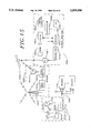
- FIG. 15 is a functional block diagram of a television video and data transmission system.
- FIG. 16 is a timing diagram showing the vertical blanking interval (VBI) lines of field 1 and field 2 of an interlaced raster scanning pattern of a conventional television and data in the VBI according to the present invention.
- VBI vertical blanking interval
- a video system which includes a cable box 14, a VCR 12, and a television (TV) 10.
- the television 10 includes a tuner 20 and monitor 22 and in addition includes a command controller 24, compressed code decoder 26, clock 28, IR detector 30, and IR emitter 32.
- a remote controller 18 with an IR emitter 19 can be used to send commands to TV 10 via IR detector 30.
- the TV 10 can then control the VCR 12 and the cable box 14 via command controller 24 and IR emitter 32 or an infrared transmitter on mouse 100.
- the mouse emits infrared signals and can be placed adjacent to the VCR 12 and/or the cable box 14. Both the cable box and the VCR have IR detectors 13 and 11, respectively.
- the input to the cable box is a television signal source 34, which can be, for example, a cable input.
- the command controller 24 can consist of a microcomputer including a CPU, a ROM, a RAM, IO ports, timers, and counters.
- the compressed decoder 26 can be used to decode compressed codes, as described in U.S. Pat. No. 5,335,079.
- the compressed codes can be input from remote controller 18 to the television 10, and used to control recording of programs by VCR 12, or used by television 10 to control tuner 20.
- the tuner 20 can be controlled to enable only certain programs or certain channels to be displayed on monitor 22. Other channels not enabled are blocked from monitor 22.
- the remote controller 18 can also be used to directly control VCR 12.
- the remote controller 18 can be an instant programmer for using compressed codes for recorder programming, as shown in FIG. 2A, or a custom programmer 500 as shown in FIG. 2B that performs all of the functions of the instant programmer while also performing the functions of a universal remote controller.
- the operation of the instant programmer 300 is described in U.S. Pat. No. 5,335,079.
- the instant programmer 300 has number keys 302, which are numbered 0 through 9, a CANCEL key 304, a REVIEW key 306, a WEEKLY key 308, a ONCE key 310 and a DAILY (M-F) key 312.
- a lid normally covers other keys, which are used to setup the instant programmer 300.
- the instant programmer has a display 350.
- the custom programmer 500 has additional keys for performing the universal remote controller function, including TV key 506, cable key 508, VCR key 510, channel up/down keys 504 and volume up/down keys 505.
- the instant programmer 300 or custom programmer 500 can transmit signals to control the television and to control program recording by VCR 12.
- FIG. 3 is a schematic of the circuitry needed to implement the instant programmer 300 or the custom programmer 500.
- the circuity consists of microcomputer 380, oscillator 382, liquid crystal display 384, key pad 386, IR transmitters 390 and red warning light emitting diode 332.
- the microcomputer 380 consists of a CPU, ROM, RAM, I/O ports, timers, counters and clock.
- the ROM is used for program storage and the RAM is used among other purposes for stack storage of the programs to be recorded.
- the liquid crystal display 384 is display 350 of FIG. 2A.
- the key pad 386 implements all the previously discussed keys.
- the IR transmitters 390 consists of front infrared (IR) diode 340, left IR diode 342, down IR diode 344, two back IR diodes 346 and right IR diode 348, or another arrangement of IR diodes, which can communicate to the television, VCR, and cable box.
- IR infrared
- the user performs a setup sequence for the instant programmer 300 or the custom programmer 500. Since different VCRs and cable boxes have different infrared codes, the remote controller must be set up to work with the user's equipment.
- the user looks up the number corresponding to the model/brand of VCR to be programmed in a table, which lists the VCR brand name and a two digit code. Then with the VCR tuned to Channel 3 or Channel 4, whichever is normally used, the user turns the VCR "OFF”. Then the user presses the VCR key 326. When the display shows VCR, the user presses the two-digit code looked up in the VCR model/brand table (for example 01 for RCA).
- the user points the instant programmer 300 at the VCR and then presses ENTER key 318.
- the red warning light emitting diode 332 will flash while it is sending a test signal to the VCR. If the VCR turned “ON” and changed to Channel 09, the user presses the SAVE key 316 and proceeds to the set clock step. If the VCR did not turn “ON” or turned “ON” but did not change to Channel 09 the user presses ENTER key 318 again and waits until red warning light emitting diode 332 stops flashing.
- the instant programmer 300 sends the next possible VCR code, while the red warning light emitting diode 332 is flashing.
- VCR turns "ON” and changed to Channel 09
- SAVE key 316 otherwise the user presses ENTER key 318 again until the VCR code is found that works for the VCR.
- the display shows "END” if all possible VCR codes for that brand are tried. If so, the user presses VCR key 326 code 00 and then ENTER key 318 to try all possible codes, for all brands, one at a time.
- the next setup step is to set the clock on instant programmer 300.
- the user presses the CLOCK key 320.
- the display shows: "YR:”
- ENTER key 318 Then the display shows "MO:”, and the user presses the month (for example 07 is July), and then presses ENTER key 318.
- This is repeated for "DA:” date (for example 01 for the 1st), "Hr:” hour (for example 02 for 2 o'clock), "Mn:” minute (for example 05 for 5 minutes), and "AM/PM:” 1 for AM or 2 for PM.
- the display will show "SAVE” for a few seconds and then the display will show the current time and date that have been entered.
- the setup steps are as follows. First, the number corresponding to the model/brand of cable box (converter) to be controlled is looked up in a cable box model brand table, that lists cable box brands and corresponding two digit codes. The VCR is tuned to Channel 03 or 04 and turned “OFF”. Then the cable box is tuned to Channel 02 or 03, whichever is normal, and left "ON”. Then the CABLE key 328 is pressed. When the display shows: "CA B-:” the user enters the two digit code looked up in cable box model brand table, points the instant programmer 300 at the cable box (converter) and presses ENTER key 318.
- the red warning light emitting diode 332 will flash while it is sending a test signal to the cable box. If the cable box changed to Channel 09: then the user presses SAVE key 316; however, if the cable box did not change to Channel 09 the user presses ENTER key 318 again and waits until red warning light emitting diode 332 stops flashing, while the next possible code is sent. This is repeated until the cable box changes to Channel 09 and when it does the user presses SAVE key 316. If the display shows "END" then the user has tried all possible cable box codes for that brand. If so, the user presses cable code 00 and then ENTER key 318 to try all possible brand's codes, one at a time.
- the VCR should be left OFF and the cable box ON.
- the user looks up in the television guide the compressed code for the program, which he/she wishes to record.
- the compressed code 212 is listed in the television guide, as shown in FIG. 4.
- the compressed code 212 for the program selected by the user is entered into the instant programmer 300 or the custom programmer 500 by using the number keys 302 and then the user selects how often to record the program.
- the instant programmer 300 will immediately decode the compressed code and display the date, channel and start time of the program entered by the user.
- the length of the entered program is also displayed by time bars that run across the bottom of the display. Each bar represents one hour (or less) of program.
- the user just needs to leave the instant programmer 300 near the VCR and cable box so that commands can be transmitted, and at the right time, the instant programmer 300 will turn “ON” the VCR, change to the correct channel and record the program and then turn the VCR "OFF".
- the user must just make sure to insert a blank tape.
- the display will look like this: "Guide CH TV CH”.
- ENTER key 318 For example, HBO may have assigned channel 33.
- the local channel for HBO may be 40.
- SAVE key 316 the user presses SAVE key 316.
- the user may review the settings by pressing CH key 322 and then REVIEW key 306. By repeated pressing of the REVIEW key 306 each of the set channels will scroll onto the display, one at a time.
- apparatus and methods are provided for setting a clock to the correct time.
- Apparatus and methods are also provided for synchronizing a clock to a network clock.
- FIG. 5 is a flowchart of a method for encoding a channel, date, time-of-day and length (CDTL) into a decimal compressed code 550.
- This process is done "offline” and can be implemented on a general purpose computer and is done to obtain the compressed codes 212 that are included in the program guide or calendar of FIG. 4.
- the encoding method is described in U.S. Pat. No. 5,335,079.
- One preferred embodiment uses five bits for D, which can be denoted as D 5 D 4 D 3 D 2 D 1 , and provides for 31 days in a month.
- the last encoding step is the permutate decimal number step 546, which permutes the decimal number according to permutation function 544 that is dependent on the date 548 and in particular the month and year and provides a security feature for the codes.
- the result is the decimal compressed code G 8 . . . G 2 G 1 550, which is then included in a program guide or calendar in the same manner as compressed code 212 of FIG. 4.
- FIG. 6 is a flowchart of the method for decoding a decimal compressed code 562 into channel, date, time and length 618.
- This process can be performed by compressed code decoder 26 of FIG. 1 or by microcomputer 380 of FIG. 3 in instant programmer 300 or custom programmer 500 or by a VCR.
- the decoding is described in U.S. Pat. No. 5,335,079.
- the decimal compressed code G 8 . . . G 2 G 1 564 is entered in step 562, it is necessary to invert the permutation function of steps 544 and 546 of FIG. 5.
- the first step is to extract the day from the compressed code in step 566, which extracts the day for the program in the decimal compressed code.
- step 568 The day is an input to step 568, which also receives the current day 574 from the clock 576, which is implemented by microcomputer 380.
- the clock 576 also sends the current month and year to the permutation function 570, which is dependent on the month and year.
- step 568 performs the function: if day code is same or greater than the current day from the clock, then use permutation function for the month/year on clock, otherwise use the permutation function for next month after the month on the clock and use the next year if the month on the clock is December.
- the day for the program since there is provision for preprogramming recording for one month or 31 days ahead, if the day for the program is equal to or greater than the current day of the month, then it refers to a day in the present month; otherwise, if the day for the program is less than the current day of the month, it must refer to a program in the next month.
- the extract day code step 566 which must be performed before the invert permutation of decimal compressed code step 580, is accomplished by apriori knowledge of how the permutate decimal number step 546 of FIG. 5 is performed relative to the day code information.
- the selected permutation method 578 is used in the invert permutation of decimal compressed code step 580.
- FIGS. 7A, 7B and 7C are flow diagrams of a method for synchronizing a clock to a network clock using compressed codes.
- step 1500 it is assumed that when an instant programmer or an equivalent device is manufactured that a clock calendar in the instant programmer is set to a date equal to or earlier than the date of manufacture. For example, if the instant programmer is manufactured on Mar. 1, 1995, then the clock calendar might be set to Jan. 1, 1995 at 1:00.
- step 1502 it is stated that before the instant programmer device can be used for recorder programming using compressed codes, the clock must be set to the current date and time of day.
- a user in step 1504 While viewing a program on a television, a user in step 1504 enters a first compressed code for the program currently being viewed on a channel on the television.
- This program is the so-called first program and the channel is the so-called first channel.
- the user can find the compressed code in a published television guide that contains compressed codes for programs.
- step 1506 the user enters a second compressed code for a second program immediately following the first program on the same date and on the same first channel as the first program. Then in step 1508, a first day of the month is extracted from the first compressed code. The day of the month can be extracted from the first compressed code by using step 566 shown in FIG. 6. Then in step 1510, a second day of month is extracted from the second compressed code using the same extract day code step 566.
- step 1512 it is determined whether the extracted first and second days of the month are equivalent.
- the extracted first and second days of the month should be equivalent because the compressed codes are both for programs on the same day. If in step 1512, the extracted first and second days are not equivalent, then in step 1514, the user is requested to reenter the compressed codes. If in step 1512, the extracted first and second days of the month are equivalent, then in step 1516, the day of the month and the clock calendar is replaced with the extracted day of month.
- the first compressed code is decoded into a channel (C1), a day (D1), a time of day (T1) and a length of program (L1).
- the second compressed code is decoded into a channel (C2), a day (D2), a time of day (T2), and a length of program (L2).
- the compressed codes are decoded according to the method of FIG. 6.
- C1 should equal C2 because the first and second compressed codes are for programs on the same channel.
- T2 should equal to T1 plus L1 because the second program starts immediately following the first program.
- step 1524 If in step 1524 is determined that C1 does not equal C2 or that T2 does not equal T1 plus L1, then the month on the clock calendar is incremented by one month. For example, if the month on the clock calendar is February, then the month is changed to March.
- step 1526 it is determined whether all months (January through December) for the year on the clock calendar, have been cycled through. The purpose of changing the clock calendar month and for attempting decoding of the compressed codes and performing step 1522 for different months of the year in the clock calendar, is to determine the correct month that should be set into the clock calendar. As shown in FIG. 6, steps 567, 576 and 570, the method for decoding a compressed code is a function of the month and year entered into the clock 576.
- step 524 and 526 the months for a particular year are cycled through and the compressed codes are decoded for each month entered into the clock calendar.
- step 1524 if all months have not been cycled through as determined in step 1526, then step 1518 is repeated. If all of the months have been cycled through as determined in step 1526, then the year on the clock calendar is increased by one year in step 1528 and step 1518 is repeated. Eventually, the correct month and year are entered into the clock calendar.
- the first and second compressed codes decode properly and C1 equals C2 and T2 equals T1 plus L1.
- the user is prompted to press a key when the first program ends.
- the key that the user presses can be the enter key 318 on FIG. 2A or a similar key on the controller shown in FIG. 2B.
- the user must watch the program and when it ends, the user presses the key in step 1531.
- the time T1 plus L1 is entered into the clock calendar.
- the time T1 plus L1 includes the hour and the minutes, including AM or PM.
- the time can also include seconds.
- the clock calendar is now set to the correct year, month, day of the month, and time.
- the clock calendar is also synchronized to the network clock.
- a disadvantage of the foregoing method is that it depends upon the user pressing a key at the proper time in step 1531.
- an electronic program guide is displayed on a television and can be used for synchronizing a clock to a network clock.
- a source of television signals 1270 such as a terrestrial antenna, a cable or a satellite receiver is connected to a television tuner 1272.
- the output of tuner 1272 contains video and audio television information and is connected to a picture detector (PICTURE DET) 1273 and a sound detector (SOUND DET) 1274, which produce base band video and audio signals, respectively.
- PICTURE DET picture detector
- SOUND DET sound detector
- the audio signal is coupled by a sound amplifier (SOUND AMP) 1275 to a loudspeaker 1276.
- the video signal is coupled by a video amplifier (not shown) to one input of a conventional picture-in-picture (PIP) integrated circuit chip 1279.
- PIP picture-in-picture
- An updatable data base of the schedule of program listings of all the available channels for a prescribed period of time, e.g. a day or a week, is electronically stored in a program schedule memory 1282.
- the program schedule can be periodically loaded into program schedule memory 1282 via a media (not shown), such as a floppy disk, that is read into the memory via the microprocessor 1284.
- the program schedule can be periodically sent embedded in the television signals 1270.
- the program schedule can be embedded in the vertical blanking interval lines of the television signals and retrieved by vertical blanking interval (VBI) decoder 1294, which is coupled to the output of tuner 1272 and to microprocessor 1284.
- VBI vertical blanking interval
- the program schedule can be organized in a number of different formats.
- One format is to list the program schedule in order of date and time-of-day and channel for each program, as shown in FIG. 10.
- Each program in the program schedule 1270, as shown for program 1272 in FIG. 10 contains the day 1274, the time-of-day 1276 for the start of the program, length of the program 1278, the channel number 1280 for the program, the channel call letters 1282, the compressed code 1284 for the program, the program title 1286, and a brief description 1288 of the program.
- the program listing 1292 for channel 11 (1294) on FOX 1296 has a title 1298 (MARRIED WITH CHILDREN), and a brief description 1300, which is "Married with Children-A1 scoffs at suggestion to hire professional for leak, 6 PM, 30 min.” Since the listings are in time order, listing 1302 for 2/24 at 1900 is listed after the listings for 2/24 at 1800.
- An operating program for microprocessor 1284 is stored in a read only memory (ROM) 1286.
- ROM read only memory
- a viewer input device 1288 preferably in the form of a remote controller 1310, as shown in FIG. 8B, is coupled to microprocessor 1284 to provide commands from the viewer.
- a video processor 1296 is coupled to microprocessor 1284.
- GUIDE/TV button 1312 on remote controller 1310 When the viewer wishes to see television program listings, the viewer presses GUIDE/TV button 1312 on remote controller 1310 and the microprocessor 1284 recalls a portion of the program schedule data base from memory 1282 and couples it to video processor 1296, where the program listings are formatted for display.
- the information stored in video processor 1296 is a bit map of what is displayed on the screen of television monitor 1280.
- Video processor 1296 is connected to another input of PIP chip 1279.
- input device 1288 controls microprocessor 1284 by cursor movement on the screen of television monitor 1280.
- microprocessor 1284 and video processor 1296 are coupled to a cursor position register 1298.
- the viewer can select items of information displayed on the screen by keying numbers assigned to these items into viewer input device 1288.
- Microprocessor 1284 is also coupled to tuner 1272 for changing channels and to PIP chip 1279 for selection of the mode of PIP operation.
- the microprocessor is also connected to IR transmitter 1285 for sending commands to a VCR, cable box, and/or satellite receiver.
- the commands can be channel timing commands.
- the format of an electronic program guide according to the present invention is shown in FIG. 9.
- the format has a background area 1250 and an overlayed PIP window 1252 in the upper left-hand corner of the screen.
- the real time i.e., 6:16 p.m.
- Background area 1250 includes a banner and message prompting area 1253 at the top of the screen, a program description area 1254 in the upper right-hand corner of the screen adjacent to PIP window 1252, and a program schedule area 1255 below areas 1252 and 1254.
- Program description area 1254 includes the start time and length (duration) of the program being described, as shown by program description 1300 for program 1292 in FIG. 10.
- the viewer can move a cursor 1258 vertically to highlight one of the program listings displayed in area 1255.
- the highlighted background of cursor 1258 and the background of program description area 1254 are the same color or shade.
- the real time moving images of a currently broadcast television program and the current time are displayed in PIP window 1252 and the audio portion of the television program displayed in PIP window 1252 is reproduced by the television sound system.
- Program schedule area 1255 has a column for channel name or call letters, a column for channel number, and a column for program title. Each line of area 1255 represents a separate program listing.
- All four areas of background 1250 are formatted in video processor 1296.
- the memory space of video processor 1296 corresponding to the area in which PIP window 1252 appears on the screen is left blank; i.e., although overlaid on background area 1250, PIP window 1252 does not cover up any of the information of background area 1250.
- the viewer can move cursor 1258 vertically to highlight the listing of one of the currently playing television programs displayed in area 1255.
- all the program listings for the particular screen format are stored in video processor 1296, even though only a fraction of them are displayed at the same time.
- microprocessor 1284 recalls further program listings from video processor 1296 for display on the screen of television monitor 1280.
- the PIP display, the sound reproduction, and the program description in area 1254 enable the viewer to assess better whether or not to watch the highlighted program.
- a program selection mode as the viewer moves cursor 1258 vertically from program listing to program listing in area 1255 of FIG. 9, the current television program displayed in window 1252 and the program description displayed in area 1254 automatically change accordingly to match the highlighted program in area 1255.
- tuner 1272 is set to the channel for the highlighted program listing and/or commands are sent to a cable box, VCR or satellite receiver to change channels, so that the program can be displayed in PIP window 1272.
- the microprocessor 1284 recalls the program description for the highlighted listing from program schedule memory 1282, and video processor 1296 formats this program description so it can be displayed in area 1254.
- the viewer input device 1288 preferably takes the form of a hand-held remote infrared (IR) transmitter which communicates with an infrared receiver connected to microprocessor 1284.
- the remote 1310 has a housing on which a number of control buttons are mounted.
- a GUIDE/TV button 1312, an INFO button 1314, and a VCR PLUS+ button 1316 are located above up and down arrow buttons 1318 and 1320.
- a row of buttons 1322, 1324, 1326 and 1328 which are marked with the colors red (R), green (G), yellow (Y), and blue (B), respectively, underlie down arrow button 1320. Red, green, yellow, and blue prompts are displayed in area 1253 of the electronic guides.
- the button of the IR transmitter having the corresponding color is pressed, i.e., to select the blue prompt on the screen, blue button 1328 is pressed.
- a channel specific program guide (CSPG) screen format is shown, which is another format of the electronic program guide that can be provided with the apparatus of FIG. 8A.
- All the program listings for a selected channel i.e., FOX Channel 7, are displayed in area 1255, from the currently broadcast program 1259 into the future for a specified time period, e.g., 24 hours or until the end of the day.
- Area 1255 has a column for time and a column for program title. Each line of area 1255 represents a separate program listing.
- the moving, real time images of the current television program are displayed in PIP window 1252. If the cursor also highlights the current program, a brief program description of the current program is displayed in area 1254. If the cursor highlights another program listing, such as listing 1258, a brief program description of the highlighted program is displayed in area 1254 and the current program is identified in banner 1259 by time and title.
- FIG. 11B shows a clock setting screen format, which is another format of the electronic program guide that can be provided with the apparatus of FIG. 8A.
- the user can enter a clock setting mode by selecting CHOICE 1256 by pressing a corresponding color coded key on remote 1310, such as green button 1324, which will cause video processor 1296 to display on the television monitor 1280 mode selections (not shown), one of which is a clock setting mode.
- One way of displaying mode selections is to use banner area 1253 to display color coded subareas for each mode.
- the television screen is formatted to appear as shown on FIG. 11B and the banner area 1253 indicates the mode by CLOCK SETTING 1257.
- the program schedule for the correct day can be accessed from memory and displayed in area 1255. If the user tunes to channel 7, then all the program listings for the selected channel, e.g., FOX Channel 7, are displayed in area 1255. Area 1255 has a column for time and a column for program title and each line of area 1255 represents a separate program listing.
- the moving, real time images of the current television program on the selected channel are displayed in PIP window 1252. Since the time on clock 1292 may be incorrect, the time displayed in subarea 1252a may be incorrect. Suppose for example, that the real time is 6:16 P.M., but that the time on clock 1292 is 5:10 P.M.
- the time shown in subarea 1252a, which is read from clock 1292, is displayed as 5:10 P.M., as shown in FIG. 11B.
- the goal of the clock setting mode is to properly set clock 1292 and to synchronize the clock 1292 setting to the network clock.
- the network clock is the clock used by FOX channel 7 for starting and stopping programs.
- the user When in the clock setting mode, the user is requested via banner 1262, shown in FIG. 11B, to position the cursor at the listing in area 1255 corresponding to the currently displayed program in area 1252.
- the user can do this by looking at his/her wristwatch, for example, and looking up the current program in a published program guide or the user can just select the correct program listing by watching the program shown in area 1252 until the user "knows" the correct program. For example, the user probably knows in general that it is 5 to 7 o'clock in the evening and so can position the cursor so that programs in that time frame are displayed in area 1255. Then by watching the video in area 1252, the user may be able to determine that the program being displayed in area 1252 is Married with Children.
- the brief program description in area 1254 is for the program listing selected by the cursor, shown by highlighted area 1258.
- the user moves the cursor to the correct program listing, which in this case is the 6:00 P.M. listing for Married with Children.
- the user presses the yellow button 1326 on remote controller 1310, as instructed in banner area 1262, thereby indicating that the program currently being broadcast and displayed in area 1252 corresponds to selected program listing.
- the program schedule in program schedule memory 1282 is accessed and the compressed code for the selected program is accessed. For example, as shown in FIG. 10, the compressed code for Married with Children is 25133. Then the program schedule is again read to access the program listing for the next program on channel 11. In this case the next program, as shown in FIG. 11B, is the program COPS at 6:30 P.M. The program schedule memory 1282 is read to access the compressed code for the program COPS, which as shown in FIG. 10 element 1303, is 345629.
- the compressed codes for Married with Children (25133) and for the program COPS (345629) are accessed, the compressed codes are decoded into: channel (C1), day (D1), time-of-day (T1) and length of program (L1); and C2, D2, T2 and L2, respectively.
- C1 channel
- D1 day
- T1 time-of-day
- L1 length of program
- C2 D2, T2 and L2
- a check can be performed to verify that C1 equals C2. Since the programs follow one another on the same channel, the sum of T1 plus L1 should equal T2. If C1 does not equal C2 or if the sum of T1 plus L1 does not equal T2, then the user is warned that a mistake has occurred.
- FIGS. 12A, 12B and 12C are flow diagrams of a method for synchronizing a clock to a network clock according the present invention.
- the user selects a clock setting mode.
- the currently tuned channel is displayed in a first area in the monitor as a picture in picture (PIP) reduced video.
- a program schedule for the currently tune channel is access from memory for the current date and displayed on a second area of the monitor.
- the monitor is assumed to be a television or an equivalent display device.
- a brief description for a program is displayed in a third area of the monitor.
- step 1606 a display message requests the user to position a cursor on the program listing in the second area of the monitor that corresponds to the program being displayed in the first area.
- the user is then requested to press a first button to select the program listing that the user believes corresponds to the program displayed in the first area of the monitor.
- step 1608 the user positions the cursor to a program listing and presses the first button.
- step 1610 the program schedule is accessed and a first compressed code for the selected program listing is read from memory.
- a second compressed code for the next in time program listing for the same channel is also accessed from the memory.
- the first compressed code is decoded into channel (C1), day (D1), time of day (T1) and length of program (L1).
- the second compressed code is decoded into C2, D2, T2, and L2.
- the decoding can be performed according to the method of FIG. 6.
- step 1614 it is determined whether C1 is equal to the currently tuned to channel. This can be determined by microprocessor 1284, which controls the tuner 1272 and also receives the decoded compressed codes from compressed code decoder 1290. If C1 does not equal the currently tuned to channel, then in step 1616, the user is informed that the selected program listing is incorrect and step 1606 is repeated. If C1 does equal the currently tuned to channel then in step 1618, it is determined whether C1 equals C2. C1 should equal C2, because C2 has been decoded from a compressed code that is the next in time program listing for the same channel as C1. If C1 does not equal C2, then an error has occurred and the user is warned to start again in step 1620. Then in step 1622 it is determined whether T1 plus L1 equals T2. If not, an error has occurred and the user is warned to start again in step 1624.
- step 1626 the user is requested to press a second button at the end of the current program being displayed in the first area.
- step 1628 the user presses the second button at the end of the program.
- step 1630 the time T1 plus L1 is entered into the clock calendar.
- the time T1 plus L1 includes the hour and the minutes, including AM or PM. Seconds can also be included in the time.
- step 1632 the clock calendar is now synchronized to the network clock.
- a disadvantage of the foregoing method is that although the time setting for the clock is automatically determined by decoding the compressed code, the user must press a button at the end of the program. Thus, the user must pay attention to the program to detect the end of the program and press the button at the correct time so that T1 plus L1 can entered into the clock calendar to synchronize the clock calendar to the network clock.
- Another embodiment of the present invention is to embed in a video signal for the program, an end of program indication 1652, as shown in FIG. 13A.
- the first program 1650 is followed by the second program 1654.
- the end of program indication 1652 is sent embedded in the video signal.
- a common way of embedding auxiliary information in a video signal is to embed the auxiliary information into the vertical blanking interval of the video signal. If an end of program indication 1652 is embedded in the video signal at the end of the first program, then it is not necessary for a user to press a button at the end of the first program.
- Steps 1626 and 1628 in FIG. 12C can be replaced with step 1666 shown in FIG. 13B. In step 1666, it is determined whether an end of program indication has been detected.
- FIG. 14 is a schematic diagram illustrating the interlaced scanning pattern 10100 on a screen of a conventional television receiver.
- a video display scans the beam from the top left hand corner and scans across the screen (line 22, field 1 in FIG. 14). After it finishes scanning the first line, the beam returns to the left hand side during a period known as a horizontal blanking interval and repeats scanning along another line which is parallel to but lower than the previous line (line 23, field 1 in FIG. 14). The scanning continues along the lines until the beam reaches the center of the bottom part of the screen (line 263, field 1) to complete field 1, which is comprised of lines 10102.
- each field contains 262.5 horizontal lines and a pair of fields constitute a single 525 line video frame and creates one video picture at one instant in time on the video display.
- VBI vertical blanking interval
- Apparatus and methods using the NTSC standard with 21 lines in each VBI are well known in the art and therefore are not discussed in detail herein.
- the VBI can be used for conveying auxiliary information from a television network or station to an audience.
- closed caption data associated with the television program are transmitted as encoded composite data signals in VBI line 21, field 1 of the standard NTSC video signal, as shown in FIG. 16.
- Lines 1 through 9 of the VBI of each field are generally used for vertical synchronization and post equalizing pulses.
- lines 10 through 21 are available for auxiliary information.
- FIG. 15 is a functional block diagram of a data transmission system.
- the terms “broadcast” and “transmit” are used interchangeably for the transmission of signals over cable or fiber optics, to or from satellites, over the air, and the like.
- a network head end 10001 transmits a composite television signal containing inserted information in a portion thereof, typically the vertical blanking interval, to a satellite 10002 which rebroadcasts the same to a local affiliate 10003.
- the affiliate 10003 may further insert data into the vertical blanking interval of the received television signal and transmit the same to a local cable head end 10004.
- the cable head end 10004 receives television signals from a plurality of sources (including satellites) and may further insert data into the vertical blanking interval of any of the television signals.
- the signals from the plurality of sources are combined into a composite television signal, amplified, and provided over a cable to a plurality of individual receivers 10005, which can include televisions, cable boxes, VCRs and satellite receivers.
- the individual receivers 10005 may receive signals directly from the local affiliate 10003 by air, which may include the use of a satellite 10002, or by cable.
- Each receiver 10005 includes a VBI decoder, which can include a VBI slicer and closed caption decoder, that scans VBI lines 10-21 of both fields 1 and 2.
- VBI decoder can include a VBI slicer and closed caption decoder, that scans VBI lines 10-21 of both fields 1 and 2.
- Closed captioning and text mode data are generally transmitted on VBI line 21, field 1 of the standard NTSC video signal, at a rate of 2 bytes for each VBI line 21, field 1, as shown by closed caption data 10112 in FIG. 16.
- Extended data services (EDS) data can be transmitted on VBI line 21, field 2, as shown by EDS data 10116 in FIG. 16, at a rate of 2 bytes per VBI line 21, field 2.
- EDS Extended data services
- Caption data decoding is further described in the following specifications, which are hereby incorporated by reference herein: Title 47, Code of Federal Regulations, Part 15 as amended by GEN. Docket No. 91-1; FCC 91-119; "CLOSED CAPTION DECODER REQUIREMENTS FOR THE TELEVISION RECEIVERS”; Title 47, C.F.R., Part 73.682(a)(22), Caption Transmission format; Title 47, C.F.R. Part 73.699, FIG. 6; "TELEVISION SYNCHRONIZING WAVE FORM"; Title 47, C.F.R., Part 73.699, FIG. 17a; "LINE 21, FIELD 1 DATA SIGNAL FORMAT”; and PBS Engineering Report No.
- Extended data services are further described in Recommended Practice for Line 21 Data Service, Electronics Industries Association, EIA-608 (drafts Oct. 12, 1992 and Jun. 17, 1993), the subject matter of which is incorporated herein by reference.
- the extended data includes, among other information, program name, program length, length into show, channel number, network affiliation, station call letters, UCT (universal coordinated time) time, time zone, and daylight savings time usage.
- the inserter can insert data other than closed captioning data and EDS data into the television signal.
- the inserted data 10114 can include an end of program indication, which is inserted into either or both fields in any VBI line between 10 and 21.
- the end of program indication can be inserted and sent at the end of a program, as shown in FIG. 13A.
- the end of program indication which can be a special code, can be transmitted at 2 or 4 bytes/line.
Abstract
Description
Claims (35)
Priority Applications (1)
| Application Number | Priority Date | Filing Date | Title |
|---|---|---|---|
| US08/421,385 US5559550A (en) | 1995-03-01 | 1995-04-13 | Apparatus and methods for synchronizing a clock to a network clock |
Applications Claiming Priority (3)
| Application Number | Priority Date | Filing Date | Title |
|---|---|---|---|
| US08/396,559 US5552837A (en) | 1995-03-01 | 1995-03-01 | Remote controller for scanning data and controlling a video system |
| US40404695A | 1995-03-14 | 1995-03-14 | |
| US08/421,385 US5559550A (en) | 1995-03-01 | 1995-04-13 | Apparatus and methods for synchronizing a clock to a network clock |
Related Parent Applications (1)
| Application Number | Title | Priority Date | Filing Date |
|---|---|---|---|
| US40404695A Continuation-In-Part | 1995-03-01 | 1995-03-14 |
Publications (1)
| Publication Number | Publication Date |
|---|---|
| US5559550A true US5559550A (en) | 1996-09-24 |
Family
ID=27015556
Family Applications (1)
| Application Number | Title | Priority Date | Filing Date |
|---|---|---|---|
| US08/421,385 Expired - Lifetime US5559550A (en) | 1995-03-01 | 1995-04-13 | Apparatus and methods for synchronizing a clock to a network clock |
Country Status (1)
| Country | Link |
|---|---|
| US (1) | US5559550A (en) |
Cited By (248)
| Publication number | Priority date | Publication date | Assignee | Title |
|---|---|---|---|---|
| WO1997018670A1 (en) * | 1995-11-13 | 1997-05-22 | Hyundai Electronics America, Inc. | Electronic program guide with enhanced presentation |
| WO1998006219A1 (en) * | 1996-08-06 | 1998-02-12 | Starsight Telecast, Incorporated | Electronic program guide with interactive areas |
| US5754258A (en) * | 1994-08-16 | 1998-05-19 | Sony Corporation | Program switching device and method |
| US5801747A (en) * | 1996-11-15 | 1998-09-01 | Hyundai Electronics America | Method and apparatus for creating a television viewer profile |
| US5812205A (en) * | 1994-05-04 | 1998-09-22 | Starsight Telecast Incorporated | Automatic time set in a television system |
| US5815145A (en) * | 1995-08-21 | 1998-09-29 | Microsoft Corporation | System and method for displaying a program guide for an interactive televideo system |
| US5850218A (en) | 1997-02-19 | 1998-12-15 | Time Warner Entertainment Company L.P. | Inter-active program guide with default selection control |
| US5903262A (en) * | 1995-07-31 | 1999-05-11 | Kabushiki Kaisha Toshiba | Interactive television system with script interpreter |
| US5907323A (en) * | 1995-05-05 | 1999-05-25 | Microsoft Corporation | Interactive program summary panel |
| EP0944252A1 (en) * | 1998-03-17 | 1999-09-22 | Sony Corporation | Information processing apparatus and method, digital signal demodulation apparatus and method, and providing medium |
| EP0944253A1 (en) * | 1998-03-17 | 1999-09-22 | Sony Corporation | Epg receiving apparatus and method and providing medium |
| EP0947093A1 (en) * | 1996-12-19 | 1999-10-06 | Index Systems, Inc. | Epg with advertising inserts |
| USD415161S (en) * | 1998-03-12 | 1999-10-12 | Corporate Media Partners | Three sided remote control |
| US5966187A (en) * | 1995-03-31 | 1999-10-12 | Samsung Electronics Co., Ltd. | Program guide signal receiver and method thereof |
| US5973682A (en) * | 1997-10-17 | 1999-10-26 | Sony Corporation | Method and apparatus for indicating functional areas of a graphical user interface |
| US6020930A (en) * | 1997-08-28 | 2000-02-01 | Sony Corporation | Method and apparatus for generating and displaying a broadcast system program guide |
| US6025869A (en) * | 1995-01-05 | 2000-02-15 | Music Corporation | Video viewing supervision system |
| US6034677A (en) * | 1997-10-17 | 2000-03-07 | Sony Corporation | Method and apparatus for displaying an electronic program guide |
| WO2000021285A1 (en) * | 1998-10-05 | 2000-04-13 | Thomson Multimedia | Method and device for service data management in a television system |
| EP1010319A1 (en) * | 1997-03-10 | 2000-06-21 | Joseph Enterprises, Inc | Simplified vcr programmer |
| US6111614A (en) * | 1997-10-17 | 2000-08-29 | Sony Corporation | Method and apparatus for displaying an electronic menu having components with differing levels of transparency |
| WO2000056072A1 (en) * | 1999-03-15 | 2000-09-21 | Index Systems, Inc. | System and method for miniguide implementation |
| US6130720A (en) * | 1997-02-10 | 2000-10-10 | Matsushita Electric Industrial Co., Ltd. | Method and apparatus for providing a variety of information from an information server |
| US6157413A (en) * | 1995-11-20 | 2000-12-05 | United Video Properties, Inc. | Interactive special events video signal navigation system |
| US6160545A (en) * | 1997-10-24 | 2000-12-12 | General Instrument Corporation | Multi-regional interactive program guide for television |
| US6163345A (en) * | 1995-01-04 | 2000-12-19 | Sony Corportion | Method and apparatus for providing station and programming information in a multiple station broadcast system |
| US6177931B1 (en) | 1996-12-19 | 2001-01-23 | Index Systems, Inc. | Systems and methods for displaying and recording control interface with television programs, video, advertising information and program scheduling information |
| US6204841B1 (en) * | 1996-07-19 | 2001-03-20 | Samsung Electronics Co., Ltd. | Programmed recording device and method of cable television broadcasting signal |
| US6205485B1 (en) | 1997-03-27 | 2001-03-20 | Lextron Systems, Inc | Simulcast WEB page delivery using a 3D user interface system |
| US6239794B1 (en) * | 1994-08-31 | 2001-05-29 | E Guide, Inc. | Method and system for simultaneously displaying a television program and information about the program |
| US6243142B1 (en) | 1997-10-17 | 2001-06-05 | Sony Corporation | Method and apparatus for displaying time and program status in an electronic program guide |
| US20010016946A1 (en) * | 2000-02-23 | 2001-08-23 | Tatsu Inoue | Program guide displaying apparatus and method |
| US6282152B1 (en) * | 1999-03-09 | 2001-08-28 | Timex Corporation | Learning security control device |
| WO2002011517A2 (en) * | 2000-08-09 | 2002-02-14 | Diva Systems Corporation | Method and apparatus for transitioning between interactive program guide (ipg) pages |
| US20020021309A1 (en) * | 2000-06-30 | 2002-02-21 | Tara Burnhouse | Future program action indication display |
| US20020056104A1 (en) * | 2000-06-30 | 2002-05-09 | Tara Burnhouse | Folder-style program guide with categories and sub-categories |
| US20020059599A1 (en) * | 1995-10-02 | 2002-05-16 | Starsight Telecast Incorporated | Interactive computer system for providing television schedule information |
| US20020088004A1 (en) * | 2000-08-28 | 2002-07-04 | Sony Corporation | System and method for interactive television |
| US6424791B1 (en) | 1998-03-27 | 2002-07-23 | Sony Corporation | System and method for providing selection of timer recording |
| US6426779B1 (en) | 1995-01-04 | 2002-07-30 | Sony Electronics, Inc. | Method and apparatus for providing favorite station and programming information in a multiple station broadcast system |
| US20020120933A1 (en) * | 1998-04-30 | 2002-08-29 | United Video Properties, Inc | Program guide system with flip and browse advertisements |
| US6445398B1 (en) | 1998-02-04 | 2002-09-03 | Corporate Media Partners | Method and system for providing user interface for electronic program guide |
| US20020129376A1 (en) * | 2000-09-08 | 2002-09-12 | Tadamasa Kitsukawa | Virtual channel system for web appliance, including interactive television |
| US20020144288A1 (en) * | 2001-03-09 | 2002-10-03 | Tadamasa Kitsukawa | System and method for allowing access to web sites using interactive television |
| US20020144258A1 (en) * | 2001-03-09 | 2002-10-03 | Tadamasa Kitsukawa | System and method for billing for interactive television |
| US20020157092A1 (en) * | 2001-04-23 | 2002-10-24 | Sony Corporation | System and method for pulling internet content onto interactive television |
| US20020157107A1 (en) * | 2001-04-23 | 2002-10-24 | Sony Corporation | Interactive television system |
| US20020157109A1 (en) * | 2001-04-21 | 2002-10-24 | Sony Corporation | System and method for interactive television |
| US20020157100A1 (en) * | 2001-04-23 | 2002-10-24 | Sony Corporation | Electronic program guide including virtual channels for interactive television |
| US20020157108A1 (en) * | 2001-04-23 | 2002-10-24 | Sony Corporation | Gateway screen for interactive television |
| US6476825B1 (en) | 1998-05-13 | 2002-11-05 | Clemens Croy | Hand-held video viewer and remote control device |
| US6481012B1 (en) | 1999-10-27 | 2002-11-12 | Diva Systems Corporation | Picture-in-picture and multiple video streams using slice-based encoding |
| US20020172095A1 (en) * | 2001-03-14 | 2002-11-21 | Pandipati Radha K.C. | Electric clocks and remote controller |
| US20020184627A1 (en) * | 1997-02-28 | 2002-12-05 | Alba Theresa A. | Television control interface with electronic guide |
| US6499138B1 (en) | 1998-09-10 | 2002-12-24 | Bellsouth Intellectual Property Corporation | Methods and systems for providing information about programs available for viewing |
| US20020199195A1 (en) * | 1995-12-22 | 2002-12-26 | Christopher Townsend | Receivers for television signals |
| US6505348B1 (en) | 1998-07-29 | 2003-01-07 | Starsight Telecast, Inc. | Multiple interactive electronic program guide system and methods |
| US20030009758A1 (en) * | 1995-12-22 | 2003-01-09 | Christopher Townsend | Receivers for television signals |
| US6509908B1 (en) | 1998-05-13 | 2003-01-21 | Clemens Croy | Personal navigator system |
| US6518986B1 (en) | 1997-10-17 | 2003-02-11 | Sony Corporation | Method and apparatus for providing an on-screen guide for a multiple channel broadcasting system |
| KR100376171B1 (en) * | 1998-01-26 | 2003-03-15 | 인덱스 시스템즈, 인코포레이티드 | Picture-in-guide generator |
| US6539212B1 (en) * | 1995-10-24 | 2003-03-25 | Koninklijke Philips Electronics N.V. | Radio broadcasting service, a transmitter and a receiver for use in such a system, a radio broadcasting method and a radio broadcasting signal, in which a data signal accompanying a program signal includes data of a data service and information pertaining to the data service |
| US6539210B1 (en) | 1999-10-13 | 2003-03-25 | Openglobe, Inc. | Automatic assignment and tuning of radio call letters to radio presets |
| US20030105803A1 (en) * | 2000-08-25 | 2003-06-05 | Wolfgang Daum | Arbitrating clock synchronization system |
| US6577350B1 (en) | 1998-12-21 | 2003-06-10 | Sony Corporation | Method and apparatus for displaying an electronic program guide |
| US20030110499A1 (en) * | 1998-03-04 | 2003-06-12 | United Video Properties, Inc. | Program guide system with targeted advertising |
| US6584153B1 (en) | 1998-07-23 | 2003-06-24 | Diva Systems Corporation | Data structure and methods for providing an interactive program guide |
| US20030131356A1 (en) * | 1998-12-21 | 2003-07-10 | Andrew M. Proehl | Method and apparatus for notification on a broadcast device |
| US6614843B1 (en) | 1999-04-15 | 2003-09-02 | Diva Systems Corporation | Stream indexing for delivery of interactive program guide |
| US20030164858A1 (en) * | 1996-05-03 | 2003-09-04 | Starsight Telecast, Inc. | Method and system for displaying banner advertisements in an electronic program guide |
| US6621870B1 (en) | 1999-04-15 | 2003-09-16 | Diva Systems Corporation | Method and apparatus for compressing video sequences |
| US20030220835A1 (en) * | 2002-05-23 | 2003-11-27 | Barnes Melvin L. | System, method, and computer program product for providing location based services and mobile e-commerce |
| US20040027485A1 (en) * | 2002-08-08 | 2004-02-12 | Pioneer Corporation | Broadcast receiver |
| US20040034866A1 (en) * | 1996-03-15 | 2004-02-19 | Index Systems, Inc. | System and method for grazing television channels from an electronic program guide |
| US6704359B1 (en) | 1999-04-15 | 2004-03-09 | Diva Systems Corp. | Efficient encoding algorithms for delivery of server-centric interactive program guide |
| US20040103439A1 (en) * | 1996-10-16 | 2004-05-27 | Gemstar Development Corporation | Access to internet data through a television system |
| US6754905B2 (en) | 1998-07-23 | 2004-06-22 | Diva Systems Corporation | Data structure and methods for providing an interactive program guide |
| US20040128699A1 (en) * | 2002-08-30 | 2004-07-01 | Alain Delpuch | Carousel proxy |
| US20040143845A1 (en) * | 2003-01-17 | 2004-07-22 | Chi-Tai Lin | Remote control video recording and playing system and its method |
| US20040230992A1 (en) * | 1993-05-27 | 2004-11-18 | Gemstar Development Corporation | Method and apparatus for displaying video clips |
| US20040261108A1 (en) * | 1996-03-15 | 2004-12-23 | Index Systems, Inc. | Combination of VCR index and EPG |
| US6868551B1 (en) | 1995-05-05 | 2005-03-15 | Microsoft Corporation | Interactive program summary panel |
| US20050158030A1 (en) * | 1999-12-10 | 2005-07-21 | Nishikawa Yuko S. | Auto title frames generation method and apparatus |
| US20050193337A1 (en) * | 1997-10-17 | 2005-09-01 | Fujio Noguchi | Method and apparatus for adjusting font size in an electronic program guide display |
| US20050229210A1 (en) * | 1999-07-28 | 2005-10-13 | Sharp Laboratories Of America, Inc. | System for displaying programming guide information |
| US6968567B1 (en) | 1999-04-15 | 2005-11-22 | Sedna Patent Services, Llc | Latency reduction in providing interactive program guide |
| US20060037040A1 (en) * | 2004-08-12 | 2006-02-16 | Mahalick Scott G | Method of transmitting audio and video signals over radio and television channels |
| US7028327B1 (en) | 2000-02-02 | 2006-04-11 | Wink Communication | Using the electronic program guide to synchronize interactivity with broadcast programs |
| US20060130093A1 (en) * | 2004-12-15 | 2006-06-15 | Liangkui Feng | Electronic program guide display and cursor control |
| US7065287B1 (en) | 1999-12-02 | 2006-06-20 | Digital Networks North America, Inc. | Apparatus, method and database for control of audio/video equipment |
| US7069571B1 (en) | 1999-06-15 | 2006-06-27 | Wink Communications, Inc. | Automated retirement of interactive applications using retirement instructions for events and program states |
| US7091968B1 (en) * | 1998-07-23 | 2006-08-15 | Sedna Patent Services, Llc | Method and apparatus for encoding a user interface |
| US7096487B1 (en) | 1999-10-27 | 2006-08-22 | Sedna Patent Services, Llc | Apparatus and method for combining realtime and non-realtime encoded content |
| US20060190966A1 (en) * | 1998-08-26 | 2006-08-24 | Mckissick Pamela L | Systems and methods for providing a program as a gift using an interactive application |
| US7222155B1 (en) | 1999-06-15 | 2007-05-22 | Wink Communications, Inc. | Synchronous updating of dynamic interactive applications |
| US20070130581A1 (en) * | 2000-02-02 | 2007-06-07 | Del Sesto Eric E | Interactive content delivery methods and apparatus |
| US20070162936A1 (en) * | 2006-01-06 | 2007-07-12 | Verizon Data Services Inc. | Interactive main menu graphical user interface systems and methods |
| US7254824B1 (en) | 1999-04-15 | 2007-08-07 | Sedna Patent Services, Llc | Encoding optimization techniques for encoding program grid section of server-centric interactive programming guide |
| US7263711B1 (en) * | 2000-09-18 | 2007-08-28 | Intel Corporation | Terminating enhanced television broadcasts |
| US20070250861A1 (en) * | 2006-03-30 | 2007-10-25 | Verizon Services Corp. | On-screen program guide with interactive programming recommendations |
| EP1734752A3 (en) * | 1996-12-19 | 2007-11-21 | Index System, Inc. | EPG with advertising inserts |
| US20070300269A1 (en) * | 2006-06-27 | 2007-12-27 | Verizon Data Services Inc. | Snippet access systems and methods |
| EP1887799A1 (en) * | 2005-05-11 | 2008-02-13 | Sharp Kabushiki Kaisha | Video preproduction limiting method and video player |
| US20080052624A1 (en) * | 2006-08-25 | 2008-02-28 | Verizon Data Services Inc. | Systems and methods for modifying content based on a positional relationship |
| US20080060038A1 (en) * | 2006-09-06 | 2008-03-06 | Verizon Data Services Inc. | Systems and methods for accessing media content |
| US20080092171A1 (en) * | 2006-10-03 | 2008-04-17 | Verizon Data Services Inc. | Control tools for media content access systems and methods |
| US20080120665A1 (en) * | 2006-11-22 | 2008-05-22 | Verizon Data Services Inc. | Audio processing for media content access systems and methods |
| US20080148317A1 (en) * | 2006-12-18 | 2008-06-19 | Verizon Services Corp. | Systems and methods for presentation of preferred program selections |
| US20080151125A1 (en) * | 2006-12-20 | 2008-06-26 | Verizon Laboratories Inc. | Systems And Methods For Controlling A Display |
| US20080155600A1 (en) * | 2006-12-20 | 2008-06-26 | United Video Properties, Inc. | Systems and methods for providing remote access to interactive media guidance applications |
| US20080155607A1 (en) * | 2006-12-20 | 2008-06-26 | United Video Properties, Inc. | Systems and methods for providing remote access to interactive media guidance applications |
| US20080155595A1 (en) * | 2006-12-21 | 2008-06-26 | Verizon Data Services Inc. | Linear program guide for media content access systems and methods |
| US20080163328A1 (en) * | 2006-12-29 | 2008-07-03 | Verizon Services Organization Inc. | Method and system for providing attribute browsing of video assets |
| US20080168377A1 (en) * | 2007-01-05 | 2008-07-10 | Verizon Data Services Inc. | Content level navigation systems and methods |
| US20080184319A1 (en) * | 1997-04-21 | 2008-07-31 | Gemstar Development Corporation | Method and apparatus for time-shifting video and text in a text-enhanced television program |
| KR100788624B1 (en) * | 1997-11-25 | 2008-08-13 | 소니 가부시끼 가이샤 | Information processing device and information processing method and broadcasting system and broadcasting method |
| US20080244654A1 (en) * | 2007-03-29 | 2008-10-02 | Verizon Laboratories Inc. | System and Method for Providing a Directory of Advertisements |
| US20080244659A1 (en) * | 2006-12-21 | 2008-10-02 | Verizon Data Services Inc. | Program guide navigation tools for media content access systems and methods |
| US20080244643A1 (en) * | 2007-03-30 | 2008-10-02 | Verizon Laboratories Inc. | System and Method for Alphanumeric Channel-Changing |
| US20080275987A1 (en) * | 1996-11-08 | 2008-11-06 | Verizon Corporate Group Services Inc. | Methods and apparatus for integrating services for accessing the world wide web |
| US20080301053A1 (en) * | 2007-05-29 | 2008-12-04 | Verizon Services Organization Inc. | Service broker |
| US20080320393A1 (en) * | 2007-06-19 | 2008-12-25 | Verizon Data Services Inc. | Program guide 3d zoom |
| US20090007179A1 (en) * | 2007-06-29 | 2009-01-01 | Verizon Laboratories, Inc. | System and method for providing an interactive program guide for past current and future programming |
| US20090003796A1 (en) * | 2007-06-29 | 2009-01-01 | Verizon Laboratories Inc. | Apparatus, method, and computer program product for receiving a command during a commercial |
| US20090006999A1 (en) * | 2007-06-28 | 2009-01-01 | Verizon Data Services Inc. | Media content recording and healing statuses |
| US20090007173A1 (en) * | 2007-06-28 | 2009-01-01 | Verizon Laboratories Inc. | Apparatus, method, and computer program product for presenting an interactive programming guide |
| US20090019488A1 (en) * | 2007-07-10 | 2009-01-15 | Verizon Data Services, Inc. | System and method for providing personal content recommendations |
| US20090069038A1 (en) * | 2007-09-07 | 2009-03-12 | United Video Properties, Inc. | Cross-platform messaging |
| US20090144624A1 (en) * | 2000-06-29 | 2009-06-04 | Barnes Jr Melvin L | System, Method, and Computer Program Product for Video Based Services and Commerce |
| US20090164906A1 (en) * | 2007-12-19 | 2009-06-25 | Verizon Data Services Inc. | Vertically oriented program guide for media content access systems and methods |
| US20090165045A1 (en) * | 2007-12-19 | 2009-06-25 | Verizon Data Services Inc. | Condensed program guide for media content access systems and methods |
| US20090205009A1 (en) * | 2008-02-13 | 2009-08-13 | Samsung Electronics Co., Ltd. | Apparatus and method for displaying channel information in digital broadcasting receiver |
| US7634787B1 (en) | 1999-06-15 | 2009-12-15 | Wink Communications, Inc. | Automatic control of broadcast and execution of interactive applications to maintain synchronous operation with broadcast programs |
| US7634788B2 (en) | 1998-11-30 | 2009-12-15 | Comcast Ip Holdings I, Llc | Service provider side interactive program guide encoder |
| US20100064320A1 (en) * | 2006-03-13 | 2010-03-11 | Verizon Services Corp. | Integrating data on program popularity into an on-screen program guide |
| US20100088725A1 (en) * | 1999-09-10 | 2010-04-08 | At&T Intellectual Property I, L.P. | Methods And Systems For Providing Information About Programs Available For Viewing |
| US20100110286A1 (en) * | 1998-02-04 | 2010-05-06 | Masuo Oku | Decoder Device And Receiver Using The Same |
| US20100157742A1 (en) * | 2008-12-19 | 2010-06-24 | Verizon Data Services, Llc | Systems and methods for radial display of time based information |
| US20100162170A1 (en) * | 2008-12-19 | 2010-06-24 | Verizon Data Services, Llc | Systems and methods for radial display of time based information |
| US7779445B2 (en) | 2003-01-30 | 2010-08-17 | United Video Properties, Inc. | Interactive television systems with digital video recording and adjustable reminders |
| US20100222090A1 (en) * | 2000-06-29 | 2010-09-02 | Barnes Jr Melvin L | Portable Communication Device and Method of Use |
| US20100235861A1 (en) * | 1995-10-02 | 2010-09-16 | Starsight Telecast, Inc. | Systems and methods for linking television viewers with advertisers and broadcasters |
| US20100251162A1 (en) * | 2006-10-03 | 2010-09-30 | Verizon Data Services Inc. | Interactive search graphical user interface systems and methods |
| US7814421B2 (en) | 1998-05-19 | 2010-10-12 | United Video Properties, Inc. | Program guide system with video window browsing |
| US7836467B2 (en) | 1998-07-23 | 2010-11-16 | Comcast Ip Holdings I, Llc | Interactive user interface |
| US20100333139A1 (en) * | 2009-06-29 | 2010-12-30 | Verizon Patent And Licensing Inc | Search-based media program guide systems and methods |
| US20100333025A1 (en) * | 2009-06-30 | 2010-12-30 | Verizon Patent And Licensing Inc. | Media Content Instance Search Methods and Systems |
| US20100333142A1 (en) * | 2009-06-29 | 2010-12-30 | Verizon Patent And Licensing Inc. | Method and apparatus for creating a personalized programming guide |
| US7895624B1 (en) | 2000-04-10 | 2011-02-22 | United Video Properties, Inc. | Interactive media guide with media guidance interface |
| US7913278B2 (en) | 1998-07-17 | 2011-03-22 | United Video Properties, Inc. | Interactive television program guide with remote access |
| US20110093893A1 (en) * | 2009-10-15 | 2011-04-21 | Verizon Patent and Licencing, Inc. | Data distribution |
| US20110107374A1 (en) * | 2009-10-30 | 2011-05-05 | Verizon Patent And Licensing, Inc. | Media content watch list systems and methods |
| US7941818B2 (en) | 1999-06-28 | 2011-05-10 | Index Systems, Inc. | System and method for utilizing EPG database for modifying advertisements |
| US20110131594A1 (en) * | 2009-11-30 | 2011-06-02 | Verizon Patent And Licensing, Inc. | Boosting factor for television content |
| US20110154399A1 (en) * | 2009-12-22 | 2011-06-23 | Verizon Patent And Licensing, Inc. | Content recommendation engine |
| US20110154403A1 (en) * | 2009-12-18 | 2011-06-23 | Rovi Technologies Corporation | Systems and methods for navigating program listings simultaneously displayed with a program in a media guidance application |
| US20110162008A1 (en) * | 2009-12-28 | 2011-06-30 | Verizon Patent And Licensing, Inc. | Dynamic program guide information |
| US20110167448A1 (en) * | 1995-10-02 | 2011-07-07 | Starsight Telecast, Inc. | Method and system for displaying advertising, video, and program schedule listing |
| US7984468B2 (en) | 2003-11-06 | 2011-07-19 | United Video Properties, Inc. | Systems and methods for providing program suggestions in an interactive television program guide |
| US8010979B2 (en) | 1998-07-07 | 2011-08-30 | United Video Properties, Inc. | Electronic program guide using markup language |
| US8032906B2 (en) | 1999-10-27 | 2011-10-04 | Comcast Ip Holdings I, Llc | Method and system for providing a program guide and multiple video streams using slice-based encoding |
| US8087047B2 (en) | 2007-04-20 | 2011-12-27 | United Video Properties, Inc. | Systems and methods for providing remote access to interactive media guidance applications |
| US8117564B2 (en) | 2009-04-10 | 2012-02-14 | United Video Properties, Inc. | Systems and methods for generating a media guidance application with multiple perspective views |
| US8255956B2 (en) | 1999-06-28 | 2012-08-28 | Cox Communications, Inc. | System and method for delivery of short-time duration video segments |
| US8265458B2 (en) | 1998-12-07 | 2012-09-11 | Index Systems, Inc. | System and method for generating video taping reminders |
| US8272011B2 (en) | 1996-12-19 | 2012-09-18 | Index Systems, Inc. | Method and system for displaying advertisements between schedule listings |
| US8286207B1 (en) * | 1998-07-13 | 2012-10-09 | Thomson Licensing | System for processing programs and system timing information derived from multiple broadcast sources |
| US8316320B2 (en) | 2006-10-03 | 2012-11-20 | Verizon Patent And Licensing Inc. | Expandable history tab in interactive graphical user interface systems and methods |
| US8327403B1 (en) | 2007-09-07 | 2012-12-04 | United Video Properties, Inc. | Systems and methods for providing remote program ordering on a user device via a web server |
| US8336071B2 (en) | 1996-12-19 | 2012-12-18 | Gemstar Development Corporation | System and method for modifying advertisement responsive to EPG information |
| US8352978B2 (en) | 1998-05-15 | 2013-01-08 | United Video Properties, Inc. | Systems and methods for advertising television networks, channels, and programs |
| US8359616B2 (en) | 2009-09-30 | 2013-01-22 | United Video Properties, Inc. | Systems and methods for automatically generating advertisements using a media guidance application |
| US8429688B1 (en) | 2001-09-19 | 2013-04-23 | At&T Intellectual Property I, L.P. | Broadcast programming guide |
| US8438601B2 (en) | 2003-07-02 | 2013-05-07 | Rovi Solutions Corporation | Resource management for a networked personal video recording system |
| US8499030B1 (en) | 1994-05-31 | 2013-07-30 | Intellectual Ventures I Llc | Software and method that enables selection of one of a plurality of network communications service providers |
| US8528032B2 (en) | 1998-07-14 | 2013-09-03 | United Video Properties, Inc. | Client-server based interactive television program guide system with remote server recording |
| US8578419B2 (en) | 1999-04-15 | 2013-11-05 | Comcast Ip Holdings I, Llc | Server-centric customized interactive program guide in an interactive television environment |
| US8578403B2 (en) | 2000-03-31 | 2013-11-05 | United Video Properties, Inc. | Systems and methods for improved audience measuring |
| US8582946B2 (en) | 2005-11-04 | 2013-11-12 | Rovi Guides, Inc. | Systems and methods for recording programs using a network recording device as supplemental storage |
| US8595778B2 (en) | 2008-11-12 | 2013-11-26 | Level 3 Communications, Llc | User authentication in a content delivery network |
| US8601526B2 (en) | 2008-06-13 | 2013-12-03 | United Video Properties, Inc. | Systems and methods for displaying media content and media guidance information |
| US8612310B2 (en) | 2005-12-29 | 2013-12-17 | United Video Properties, Inc. | Method and system for commerce in media program related merchandise |
| US8613024B2 (en) | 2005-12-13 | 2013-12-17 | United Video Properties, Inc. | Cross-platform predictive popularity ratings for use in interactive television applications |
| US8640052B2 (en) | 2009-12-31 | 2014-01-28 | Verizon Patent And Licensing Inc. | User interface enhancements for media content access systems and methods |
| US8737801B2 (en) | 2003-07-02 | 2014-05-27 | Rovi Solutions Corporation | Methods and apparatus for client aggregation of television programming in a networked personal video recording system |
| US8762492B2 (en) | 1997-09-18 | 2014-06-24 | United Video Properties, Inc. | Electronic mail reminder for an internet television program guide |
| US8761584B2 (en) | 1993-03-05 | 2014-06-24 | Gemstar Development Corporation | System and method for searching a database of television schedule information |
| US8793738B2 (en) | 1994-05-04 | 2014-07-29 | Starsight Telecast Incorporated | Television system with downloadable features |
| US8806533B1 (en) | 2004-10-08 | 2014-08-12 | United Video Properties, Inc. | System and method for using television information codes |
| US8806536B2 (en) | 1998-03-04 | 2014-08-12 | United Video Properties, Inc. | Program guide system with preference profiles |
| US8832742B2 (en) | 2006-10-06 | 2014-09-09 | United Video Properties, Inc. | Systems and methods for acquiring, categorizing and delivering media in interactive media guidance applications |
| US8856844B2 (en) | 2007-11-16 | 2014-10-07 | United Video Properties, Inc. | Systems and methods for automatically purchasing and recording popular pay programs in an interactive media delivery system |
| US8863170B2 (en) | 2000-03-31 | 2014-10-14 | United Video Properties, Inc. | System and method for metadata-linked advertisements |
| US8892495B2 (en) | 1991-12-23 | 2014-11-18 | Blanding Hovenweep, Llc | Adaptive pattern recognition based controller apparatus and method and human-interface therefore |
| US8918807B2 (en) | 1997-07-21 | 2014-12-23 | Gemstar Development Corporation | System and method for modifying advertisement responsive to EPG information |
| US8931008B2 (en) | 1999-06-29 | 2015-01-06 | United Video Properties, Inc. | Promotional philosophy for a video-on-demand-related interactive display within an interactive television application |
| US8949901B2 (en) | 2011-06-29 | 2015-02-03 | Rovi Guides, Inc. | Methods and systems for customizing viewing environment preferences in a viewing environment control application |
| US9003451B2 (en) | 1996-12-10 | 2015-04-07 | Rovi Guides, Inc. | Internet television program guide system |
| US9014546B2 (en) | 2009-09-23 | 2015-04-21 | Rovi Guides, Inc. | Systems and methods for automatically detecting users within detection regions of media devices |
| US9015750B2 (en) | 1998-05-15 | 2015-04-21 | Rovi Guides, Inc. | Interactive television program guide system for determining user values for demographic categories |
| US9042446B2 (en) | 1999-04-15 | 2015-05-26 | Comcast Ip Holdings I, Llc | Temporal slice persistence method and apparatus for delivery of interactive program guide |
| US9071372B2 (en) | 2007-12-19 | 2015-06-30 | Rovi Guides, Inc. | Methods and devices for presenting an interactive media guidance application |
| US9075861B2 (en) | 2006-03-06 | 2015-07-07 | Veveo, Inc. | Methods and systems for segmenting relative user preferences into fine-grain and coarse-grain collections |
| US9084006B2 (en) | 1998-07-17 | 2015-07-14 | Rovi Guides, Inc. | Interactive television program guide system having multiple devices within a household |
| US9094727B1 (en) | 1999-10-27 | 2015-07-28 | Cox Communications, Inc. | Multi-functional user interface using slice-based encoding |
| US9113107B2 (en) | 2005-11-08 | 2015-08-18 | Rovi Guides, Inc. | Interactive advertising and program promotion in an interactive television system |
| US9113207B2 (en) | 1995-10-02 | 2015-08-18 | Rovi Guides, Inc. | Systems and methods for contextually linking television program information |
| US9118958B2 (en) | 1999-12-10 | 2015-08-25 | Rovi Guides, Inc. | Systems and methods for coordinating interactive and passive advertisement and merchandising opportunities |
| US9125169B2 (en) | 2011-12-23 | 2015-09-01 | Rovi Guides, Inc. | Methods and systems for performing actions based on location-based rules |
| US9137491B2 (en) | 2000-02-01 | 2015-09-15 | Rovi Guides, Inc. | Methods and systems for forced advertising |
| US9143737B2 (en) | 2009-10-15 | 2015-09-22 | Verizon Patent And Licensing Inc. | Data distribution |
| US9147198B2 (en) | 2013-01-10 | 2015-09-29 | Rovi Technologies Corporation | Systems and methods for providing an interface for data driven media placement |
| US9154813B2 (en) | 2011-06-09 | 2015-10-06 | Comcast Cable Communications, Llc | Multiple video content in a composite video stream |
| US9167196B2 (en) | 2010-05-19 | 2015-10-20 | Rovi Guides, Inc. | Systems and methods for trimming recorded content using a media guidance application |
| US9166714B2 (en) | 2009-09-11 | 2015-10-20 | Veveo, Inc. | Method of and system for presenting enriched video viewing analytics |
| US9173001B1 (en) | 2006-06-27 | 2015-10-27 | Verizon Patent And Licensing Inc. | Media content access systems and methods |
| US9177081B2 (en) | 2005-08-26 | 2015-11-03 | Veveo, Inc. | Method and system for processing ambiguous, multi-term search queries |
| US9197943B2 (en) | 1998-12-03 | 2015-11-24 | Rovi Guides, Inc. | Electronic program guide with related-program search feature |
| US9204193B2 (en) | 2010-05-14 | 2015-12-01 | Rovi Guides, Inc. | Systems and methods for media detection and filtering using a parental control logging application |
| US9201627B2 (en) | 2010-01-05 | 2015-12-01 | Rovi Guides, Inc. | Systems and methods for transferring content between user equipment and a wireless communications device |
| US9218122B2 (en) | 2011-12-29 | 2015-12-22 | Rovi Guides, Inc. | Systems and methods for transferring settings across devices based on user gestures |
| US9253262B2 (en) | 2013-01-24 | 2016-02-02 | Rovi Guides, Inc. | Systems and methods for connecting media devices through web sockets |
| US9286294B2 (en) | 1992-12-09 | 2016-03-15 | Comcast Ip Holdings I, Llc | Video and digital multimedia aggregator content suggestion engine |
| US9288521B2 (en) | 2014-05-28 | 2016-03-15 | Rovi Guides, Inc. | Systems and methods for updating media asset data based on pause point in the media asset |
| US9294799B2 (en) | 2000-10-11 | 2016-03-22 | Rovi Guides, Inc. | Systems and methods for providing storage of data on servers in an on-demand media delivery system |
| US9307281B2 (en) | 2007-03-22 | 2016-04-05 | Rovi Guides, Inc. | User defined rules for assigning destinations of content |
| US9305590B2 (en) | 2007-10-16 | 2016-04-05 | Seagate Technology Llc | Prevent data storage device circuitry swap |
| US9319735B2 (en) | 1995-06-07 | 2016-04-19 | Rovi Guides, Inc. | Electronic television program guide schedule system and method with data feed access |
| US9326025B2 (en) | 2007-03-09 | 2016-04-26 | Rovi Technologies Corporation | Media content search results ranked by popularity |
| US9426509B2 (en) | 1998-08-21 | 2016-08-23 | Rovi Guides, Inc. | Client-server electronic program guide |
| US9521451B2 (en) | 1998-08-26 | 2016-12-13 | Rovi Guides, Inc. | Television chat system |
| US9535563B2 (en) | 1999-02-01 | 2017-01-03 | Blanding Hovenweep, Llc | Internet appliance system and method |
| US9591251B2 (en) | 1997-10-06 | 2017-03-07 | Rovi Guides, Inc. | Interactive television program guide system with operator showcase |
| US9674563B2 (en) | 2013-11-04 | 2017-06-06 | Rovi Guides, Inc. | Systems and methods for recommending content |
| US9679602B2 (en) | 2006-06-14 | 2017-06-13 | Seagate Technology Llc | Disc drive circuitry swap |
| US9736524B2 (en) | 2011-01-06 | 2017-08-15 | Veveo, Inc. | Methods of and systems for content search based on environment sampling |
| US9749693B2 (en) | 2006-03-24 | 2017-08-29 | Rovi Guides, Inc. | Interactive media guidance application with intelligent navigation and display features |
| US9813641B2 (en) | 2000-06-19 | 2017-11-07 | Comcast Ip Holdings I, Llc | Method and apparatus for targeting of interactive virtual objects |
| US9848276B2 (en) | 2013-03-11 | 2017-12-19 | Rovi Guides, Inc. | Systems and methods for auto-configuring a user equipment device with content consumption material |
| US9924234B2 (en) | 1998-07-23 | 2018-03-20 | Comcast Ip Holdings I, Llc | Data structure and methods for providing an interactive program |
| US9948962B2 (en) | 2014-11-13 | 2018-04-17 | Time Warner Cable Enterprises Llc | Apparatus and methods for efficient delivery of electronic program guide data |
| US10063934B2 (en) | 2008-11-25 | 2018-08-28 | Rovi Technologies Corporation | Reducing unicast session duration with restart TV |
| US10140433B2 (en) | 2001-08-03 | 2018-11-27 | Comcast Ip Holdings I, Llc | Video and digital multimedia aggregator |
| US10242376B2 (en) | 2012-09-26 | 2019-03-26 | Paypal, Inc. | Dynamic mobile seller routing |
| US10349096B2 (en) | 2001-08-03 | 2019-07-09 | Comcast Ip Holdings I, Llc | Video and digital multimedia aggregator content coding and formatting |
| US10489449B2 (en) | 2002-05-23 | 2019-11-26 | Gula Consulting Limited Liability Company | Computer accepting voice input and/or generating audible output |
| US11310555B2 (en) * | 2015-08-14 | 2022-04-19 | DISH Technologies L.L.C. | Apparatus, systems and methods for electronic program guide information presented on a display |
| US11375276B2 (en) | 2017-03-30 | 2022-06-28 | Rovi Guides, Inc. | Methods and systems for recommending media assets based on the geographic location at which the media assets are frequently consumed |
Citations (64)
| Publication number | Priority date | Publication date | Assignee | Title |
|---|---|---|---|---|
| US2188145A (en) * | 1932-09-21 | 1940-01-23 | Rca Corp | Remote indicating system |
| US2671131A (en) * | 1951-01-25 | 1954-03-02 | Clarence R Johnson | Television system for remote time indication |
| US2700065A (en) * | 1950-09-15 | 1955-01-18 | Martin E Evans | Television receiving apparatus |
| US2851550A (en) * | 1957-03-04 | 1958-09-09 | Luther A Searcy | Remote control switch for electrical appliances |
| US2856474A (en) * | 1957-10-07 | 1958-10-14 | Norris Willard Ivan | Key controlled switch box for electrical appliances |
| US3881310A (en) * | 1971-03-02 | 1975-05-06 | Diehl | Clock adapted to be synchronized by alternating current in a wireless manner |
| US4012583A (en) * | 1975-03-03 | 1977-03-15 | Motorola, Inc. | Pay TV control system |
| US4023344A (en) * | 1975-09-03 | 1977-05-17 | Kabushiki Kaisha Suwa Seikosha | Automatically corrected electronic timepiece |
| US4087958A (en) * | 1976-01-22 | 1978-05-09 | Citizen Watch Company, Limited | Timepiece apparatus |
| US4247743A (en) * | 1979-10-10 | 1981-01-27 | Hinton David O | Device for preventing unauthorized usage of appliance |
| US4321593A (en) * | 1980-02-21 | 1982-03-23 | Ho Chi C | Television set with supervisory functions of alarming burglary and safe watching distance |
| US4348696A (en) * | 1980-09-08 | 1982-09-07 | Beier Galen C | Television viewing control device |
| US4390901A (en) * | 1979-12-14 | 1983-06-28 | Edmond Keiser | Method and apparatus for controlling the operation of a television signal receiver |
| JPS58139532A (en) * | 1982-02-13 | 1983-08-18 | Akiyoshi Kinoshita | Program reservation system |
| US4475153A (en) * | 1980-05-29 | 1984-10-02 | Sony Corporation | Method and apparatus for automatic control of electronic equipment |
| US4501502A (en) * | 1983-07-21 | 1985-02-26 | James Van Orsdel | Apparatus and method for timekeeping and time correction for analog timepiece |
| US4510623A (en) * | 1982-07-23 | 1985-04-09 | General Electric Company | Television channel lockout |
| US4566033A (en) * | 1983-08-11 | 1986-01-21 | Reidenouer Linda L | Television viewing time regulator |
| US4604708A (en) * | 1981-12-07 | 1986-08-05 | Lewis Gainer R | Electronic security system for externally powered devices |
| US4605964A (en) * | 1981-12-19 | 1986-08-12 | Chard Frederick W | Method and apparatus for editing the output of a television set |
| US4620229A (en) * | 1984-04-28 | 1986-10-28 | Sony Corporation | Picture display device |
| US4623887A (en) * | 1984-05-15 | 1986-11-18 | General Electric Company | Reconfigurable remote control |
| US4647735A (en) * | 1985-05-03 | 1987-03-03 | Unimax Switch Corporation | Electrical security device |
| US4648667A (en) * | 1985-07-19 | 1987-03-10 | Baumgart Herbert P | Security device for electrical plug |
| US4718107A (en) * | 1986-02-14 | 1988-01-05 | Rca Corporation | Parental control for CATV converters |
| US4718112A (en) * | 1984-10-02 | 1988-01-05 | Sony Corporation | Remote control apparatus |
| US4768229A (en) * | 1986-07-21 | 1988-08-30 | Zenith Electronics Corporation | Restrictive access control system |
| JPS6417578A (en) * | 1987-07-13 | 1989-01-20 | Hitachi Ltd | Image pickup device |
| US4823385A (en) * | 1986-12-13 | 1989-04-18 | U.S. Philips Corporation | System for processing coded information |
| US4825200A (en) * | 1987-06-25 | 1989-04-25 | Tandy Corporation | Reconfigurable remote control transmitter |
| US4841132A (en) * | 1986-07-21 | 1989-06-20 | Matsushita Electric Industrial Co., Ltd. | Program recording scheduling apparatus using an optical reader |
| JPH01200791A (en) * | 1988-02-05 | 1989-08-11 | Toshiba Corp | Teletext receiver |
| EP0328440A1 (en) * | 1988-02-05 | 1989-08-16 | STMicroelectronics S.A. | Selection system for receiving radio or television broadcasts |
| US4866542A (en) * | 1985-12-27 | 1989-09-12 | Sony Corporation | Remote-controlling commander with multi-function rotary dial |
| US4888796A (en) * | 1987-08-31 | 1989-12-19 | Olivo Jr John W | Program material screening device |
| US4899370A (en) * | 1987-06-12 | 1990-02-06 | Matsushita Electric Industrial Co., Ltd. | Remote control apparatus for electronic equipment |
| US4903031A (en) * | 1985-03-26 | 1990-02-20 | Trio Kabushiki Kaisha | Satellite receiver |
| US4930158A (en) * | 1987-09-02 | 1990-05-29 | Vogel Peter S | Selective video playing system |
| US4965557A (en) * | 1982-07-29 | 1990-10-23 | Nokia Unterhaltungselektronik | Interactive control of entertainment electronics apparatus |
| US5001554A (en) * | 1988-12-23 | 1991-03-19 | Scientific-Atlanta, Inc. | Terminal authorization method |
| JPH0383243A (en) * | 1989-08-25 | 1991-04-09 | Nec Eng Ltd | Video tape recorder |
| EP0424725A2 (en) * | 1989-10-23 | 1991-05-02 | Societa Italiana Per Lo Sviluppo Dell'elettronica S.I.Sv.El S.P.A. | System for the automatic recording of a television programme |
| US5021916A (en) * | 1989-03-02 | 1991-06-04 | Ultimate Security, Inc. | Theft deterring security system for attachment to powered appliances |
| US5033085A (en) * | 1987-06-30 | 1991-07-16 | Goldstar Co., Ltd. | Method for controlling video and audio of a television set |
| US5046125A (en) * | 1989-07-28 | 1991-09-03 | Nec Corporation | Lock control method for on-board terminal equipment of a mobile telecommunications system |
| US5051837A (en) * | 1990-06-06 | 1991-09-24 | Mcjunkin Thomas N | Home entertainment equipment control apparatus |
| US5053797A (en) * | 1990-04-04 | 1991-10-01 | Eastman Kodak Company | System for updating software in automatic film processor |
| US5056070A (en) * | 1988-06-06 | 1991-10-08 | Sony Corporation | Timer programming apparatus |
| US5056139A (en) * | 1990-05-22 | 1991-10-08 | Texas Instruments Incorporated | Methods and apparatus for electronically limiting broadcast communication |
| US5089814A (en) * | 1989-04-28 | 1992-02-18 | Motorola, Inc. | Automatic time zone adjustment of portable receiver |
| US5166911A (en) * | 1990-01-18 | 1992-11-24 | Sony Corporation | Timer reservation recording system |
| DE4129571A1 (en) * | 1991-09-06 | 1993-03-11 | Clemens Croy | DEVICE AND METHOD FOR PROGRAMMING VIDEO RECORDERS |
| US5226090A (en) * | 1989-12-29 | 1993-07-06 | Pioneer Electronic Corporation | Voice-operated remote control system |
| US5228077A (en) * | 1987-12-02 | 1993-07-13 | Universal Electronics Inc. | Remotely upgradable universal remote control |
| US5251191A (en) * | 1989-10-26 | 1993-10-05 | Diehl Gmbh & Co. | Remotely-synchronizable time display |
| US5255313A (en) * | 1987-12-02 | 1993-10-19 | Universal Electronics Inc. | Universal remote control system |
| US5258964A (en) * | 1990-09-07 | 1993-11-02 | Nec Corporation | Apparatus for displaying time-of-day data adaptively to different time zones |
| US5265070A (en) * | 1989-11-08 | 1993-11-23 | Seiko Epson Corporation | Receiving device with timekeeping function |
| US5303063A (en) * | 1991-12-13 | 1994-04-12 | Thomson Consumer Electronics, Inc. | VCR control of a cable converter unit |
| US5307173A (en) * | 1988-12-23 | 1994-04-26 | Gemstar Development Corporation | Apparatus and method using compressed codes for television program record scheduling |
| US5319374A (en) * | 1993-02-02 | 1994-06-07 | Trimble Navigation Limited | Precise universal time for vehicles |
| US5335079A (en) * | 1988-12-23 | 1994-08-02 | Gemstar Development Corporation | Apparatus and method using compressed codes for recorder preprogramming |
| JPH0757334A (en) * | 1993-08-09 | 1995-03-03 | Toshiba Corp | Video recording reserving device |
| US5414756A (en) * | 1992-06-26 | 1995-05-09 | Smart Vcr Limited Partnership | Telephonically programmable apparatus |
-
1995
- 1995-04-13 US US08/421,385 patent/US5559550A/en not_active Expired - Lifetime
Patent Citations (66)
| Publication number | Priority date | Publication date | Assignee | Title |
|---|---|---|---|---|
| US2188145A (en) * | 1932-09-21 | 1940-01-23 | Rca Corp | Remote indicating system |
| US2700065A (en) * | 1950-09-15 | 1955-01-18 | Martin E Evans | Television receiving apparatus |
| US2671131A (en) * | 1951-01-25 | 1954-03-02 | Clarence R Johnson | Television system for remote time indication |
| US2851550A (en) * | 1957-03-04 | 1958-09-09 | Luther A Searcy | Remote control switch for electrical appliances |
| US2856474A (en) * | 1957-10-07 | 1958-10-14 | Norris Willard Ivan | Key controlled switch box for electrical appliances |
| US3881310A (en) * | 1971-03-02 | 1975-05-06 | Diehl | Clock adapted to be synchronized by alternating current in a wireless manner |
| US4012583A (en) * | 1975-03-03 | 1977-03-15 | Motorola, Inc. | Pay TV control system |
| US4023344A (en) * | 1975-09-03 | 1977-05-17 | Kabushiki Kaisha Suwa Seikosha | Automatically corrected electronic timepiece |
| US4087958A (en) * | 1976-01-22 | 1978-05-09 | Citizen Watch Company, Limited | Timepiece apparatus |
| US4247743A (en) * | 1979-10-10 | 1981-01-27 | Hinton David O | Device for preventing unauthorized usage of appliance |
| US4390901A (en) * | 1979-12-14 | 1983-06-28 | Edmond Keiser | Method and apparatus for controlling the operation of a television signal receiver |
| US4321593A (en) * | 1980-02-21 | 1982-03-23 | Ho Chi C | Television set with supervisory functions of alarming burglary and safe watching distance |
| US4475153A (en) * | 1980-05-29 | 1984-10-02 | Sony Corporation | Method and apparatus for automatic control of electronic equipment |
| US4348696A (en) * | 1980-09-08 | 1982-09-07 | Beier Galen C | Television viewing control device |
| US4604708A (en) * | 1981-12-07 | 1986-08-05 | Lewis Gainer R | Electronic security system for externally powered devices |
| US4604708B1 (en) * | 1981-12-07 | 1997-10-14 | Gainer R Lewis | Electronic security system for externally powered devices |
| US4605964A (en) * | 1981-12-19 | 1986-08-12 | Chard Frederick W | Method and apparatus for editing the output of a television set |
| JPS58139532A (en) * | 1982-02-13 | 1983-08-18 | Akiyoshi Kinoshita | Program reservation system |
| US4510623A (en) * | 1982-07-23 | 1985-04-09 | General Electric Company | Television channel lockout |
| US4965557A (en) * | 1982-07-29 | 1990-10-23 | Nokia Unterhaltungselektronik | Interactive control of entertainment electronics apparatus |
| US4501502A (en) * | 1983-07-21 | 1985-02-26 | James Van Orsdel | Apparatus and method for timekeeping and time correction for analog timepiece |
| US4566033A (en) * | 1983-08-11 | 1986-01-21 | Reidenouer Linda L | Television viewing time regulator |
| US4620229A (en) * | 1984-04-28 | 1986-10-28 | Sony Corporation | Picture display device |
| US4623887A (en) * | 1984-05-15 | 1986-11-18 | General Electric Company | Reconfigurable remote control |
| US4718112A (en) * | 1984-10-02 | 1988-01-05 | Sony Corporation | Remote control apparatus |
| US4903031A (en) * | 1985-03-26 | 1990-02-20 | Trio Kabushiki Kaisha | Satellite receiver |
| US4647735A (en) * | 1985-05-03 | 1987-03-03 | Unimax Switch Corporation | Electrical security device |
| US4648667A (en) * | 1985-07-19 | 1987-03-10 | Baumgart Herbert P | Security device for electrical plug |
| US4866542A (en) * | 1985-12-27 | 1989-09-12 | Sony Corporation | Remote-controlling commander with multi-function rotary dial |
| US4718107A (en) * | 1986-02-14 | 1988-01-05 | Rca Corporation | Parental control for CATV converters |
| US4768229A (en) * | 1986-07-21 | 1988-08-30 | Zenith Electronics Corporation | Restrictive access control system |
| US4841132A (en) * | 1986-07-21 | 1989-06-20 | Matsushita Electric Industrial Co., Ltd. | Program recording scheduling apparatus using an optical reader |
| US4823385A (en) * | 1986-12-13 | 1989-04-18 | U.S. Philips Corporation | System for processing coded information |
| US4899370A (en) * | 1987-06-12 | 1990-02-06 | Matsushita Electric Industrial Co., Ltd. | Remote control apparatus for electronic equipment |
| US4825200A (en) * | 1987-06-25 | 1989-04-25 | Tandy Corporation | Reconfigurable remote control transmitter |
| US5033085A (en) * | 1987-06-30 | 1991-07-16 | Goldstar Co., Ltd. | Method for controlling video and audio of a television set |
| JPS6417578A (en) * | 1987-07-13 | 1989-01-20 | Hitachi Ltd | Image pickup device |
| US4888796A (en) * | 1987-08-31 | 1989-12-19 | Olivo Jr John W | Program material screening device |
| US4930158A (en) * | 1987-09-02 | 1990-05-29 | Vogel Peter S | Selective video playing system |
| US5255313A (en) * | 1987-12-02 | 1993-10-19 | Universal Electronics Inc. | Universal remote control system |
| US5228077A (en) * | 1987-12-02 | 1993-07-13 | Universal Electronics Inc. | Remotely upgradable universal remote control |
| JPH01200791A (en) * | 1988-02-05 | 1989-08-11 | Toshiba Corp | Teletext receiver |
| EP0328440A1 (en) * | 1988-02-05 | 1989-08-16 | STMicroelectronics S.A. | Selection system for receiving radio or television broadcasts |
| US5056070A (en) * | 1988-06-06 | 1991-10-08 | Sony Corporation | Timer programming apparatus |
| US5063543A (en) * | 1988-06-06 | 1991-11-05 | Sony Corporation | Timer programming apparatus |
| US5335079A (en) * | 1988-12-23 | 1994-08-02 | Gemstar Development Corporation | Apparatus and method using compressed codes for recorder preprogramming |
| US5307173A (en) * | 1988-12-23 | 1994-04-26 | Gemstar Development Corporation | Apparatus and method using compressed codes for television program record scheduling |
| US5001554A (en) * | 1988-12-23 | 1991-03-19 | Scientific-Atlanta, Inc. | Terminal authorization method |
| US5021916A (en) * | 1989-03-02 | 1991-06-04 | Ultimate Security, Inc. | Theft deterring security system for attachment to powered appliances |
| US5089814A (en) * | 1989-04-28 | 1992-02-18 | Motorola, Inc. | Automatic time zone adjustment of portable receiver |
| US5046125A (en) * | 1989-07-28 | 1991-09-03 | Nec Corporation | Lock control method for on-board terminal equipment of a mobile telecommunications system |
| JPH0383243A (en) * | 1989-08-25 | 1991-04-09 | Nec Eng Ltd | Video tape recorder |
| EP0424725A2 (en) * | 1989-10-23 | 1991-05-02 | Societa Italiana Per Lo Sviluppo Dell'elettronica S.I.Sv.El S.P.A. | System for the automatic recording of a television programme |
| US5251191A (en) * | 1989-10-26 | 1993-10-05 | Diehl Gmbh & Co. | Remotely-synchronizable time display |
| US5265070A (en) * | 1989-11-08 | 1993-11-23 | Seiko Epson Corporation | Receiving device with timekeeping function |
| US5226090A (en) * | 1989-12-29 | 1993-07-06 | Pioneer Electronic Corporation | Voice-operated remote control system |
| US5166911A (en) * | 1990-01-18 | 1992-11-24 | Sony Corporation | Timer reservation recording system |
| US5053797A (en) * | 1990-04-04 | 1991-10-01 | Eastman Kodak Company | System for updating software in automatic film processor |
| US5056139A (en) * | 1990-05-22 | 1991-10-08 | Texas Instruments Incorporated | Methods and apparatus for electronically limiting broadcast communication |
| US5051837A (en) * | 1990-06-06 | 1991-09-24 | Mcjunkin Thomas N | Home entertainment equipment control apparatus |
| US5258964A (en) * | 1990-09-07 | 1993-11-02 | Nec Corporation | Apparatus for displaying time-of-day data adaptively to different time zones |
| DE4129571A1 (en) * | 1991-09-06 | 1993-03-11 | Clemens Croy | DEVICE AND METHOD FOR PROGRAMMING VIDEO RECORDERS |
| US5303063A (en) * | 1991-12-13 | 1994-04-12 | Thomson Consumer Electronics, Inc. | VCR control of a cable converter unit |
| US5414756A (en) * | 1992-06-26 | 1995-05-09 | Smart Vcr Limited Partnership | Telephonically programmable apparatus |
| US5319374A (en) * | 1993-02-02 | 1994-06-07 | Trimble Navigation Limited | Precise universal time for vehicles |
| JPH0757334A (en) * | 1993-08-09 | 1995-03-03 | Toshiba Corp | Video recording reserving device |
Non-Patent Citations (14)
| Title |
|---|
| Daniel F. Walsh Jr., Timing Considerations In RF Two Way Data Collection And Polling, Jerrold Applied Media Lab , 1989 NCTA Technical Papers, pp. 47 56. * |
| Daniel F. Walsh Jr., Timing Considerations In RF Two Way Data Collection And Polling, Jerrold-Applied Media Lab, 1989 NCTA Technical Papers, pp. 47-56. |
| Daniel H. Smart, Innovative Aspects Of A Switched Star Cabled Television Distribution System, British Cable Services Limited , 1987 NCTA Technical Papers, pp. 26 35. * |
| Daniel H. Smart, Innovative Aspects Of A Switched Star Cabled Television Distribution System, British Cable Services Limited, 1987 NCTA Technical Papers, pp. 26-35. |
| Gary Libman, Times Staff Writer Chaining The Channels, A New Generation of Television Blocking Systems Allows More Options for Parents Seeking to Control Kids Viewing, Los Angeles Times Aug. 9, 1993. * |
| Gary Libman, Times Staff Writer Chaining The Channels, A New Generation of Television Blocking Systems Allows More Options for Parents Seeking to Control Kids' Viewing, Los Angeles Times Aug. 9, 1993. |
| Gregory F. Vaeth, John Feras, Enertec, Inc., The Addressable Controller Of The Future, General Instrument/Jerrold Communication , 1990 NCTA Technical Papers, pp. 274 279. * |
| Gregory F. Vaeth, John Feras, Enertec, Inc., The Addressable Controller Of The Future, General Instrument/Jerrold Communication, 1990 NCTA Technical Papers, pp. 274-279. |
| James A. Chiddix, David M. Pangrac, Off Premises Broadband Addressability: A CATV Industry Challenge, American Television and Communications Corporation , Stamford Connecticut, 1989 NCTA Technical Papers, pp. 57 64. * |
| James A. Chiddix, David M. Pangrac, Off-Premises Broadband Addressability: A CATV Industry Challenge, American Television and Communications Corporation, Stamford Connecticut, 1989 NCTA Technical Papers, pp. 57-64. |
| Lamar West, Himanshu Parikh, Neil Robertson, Allen Childers, Mark Doremus, Off Premises Technology Comparisons, Scientific Atlanta 1989 NCTA Technical Papers, pp. 39 56. * |
| Lamar West, Himanshu Parikh, Neil Robertson, Allen Childers, Mark Doremus, Off Premises Technology Comparisons, Scientific-Atlanta 1989 NCTA Technical Papers, pp. 39-56. |
| Richard G. Merrell, Mack S. Daily, An Auto Dialer Approach To Pay Per View Purchasing, Zenith Electronics Corporation , Glenview, Illinois, 1989 NCTA Technical Papers, pp. 34 38. * |
| Richard G. Merrell, Mack S. Daily, An Auto-Dialer Approach To Pay-Per-View Purchasing, Zenith Electronics Corporation, Glenview, Illinois, 1989 NCTA Technical Papers, pp. 34-38. |
Cited By (494)
| Publication number | Priority date | Publication date | Assignee | Title |
|---|---|---|---|---|
| US8892495B2 (en) | 1991-12-23 | 2014-11-18 | Blanding Hovenweep, Llc | Adaptive pattern recognition based controller apparatus and method and human-interface therefore |
| US9286294B2 (en) | 1992-12-09 | 2016-03-15 | Comcast Ip Holdings I, Llc | Video and digital multimedia aggregator content suggestion engine |
| US8761584B2 (en) | 1993-03-05 | 2014-06-24 | Gemstar Development Corporation | System and method for searching a database of television schedule information |
| US20040230992A1 (en) * | 1993-05-27 | 2004-11-18 | Gemstar Development Corporation | Method and apparatus for displaying video clips |
| US20100115556A1 (en) * | 1993-05-27 | 2010-05-06 | Yuen Henry C | Method and apparatus for displaying video clips |
| US20110138419A1 (en) * | 1993-05-27 | 2011-06-09 | Yuen Henry C | Method and apparatus for displaying video clips |
| US5812205A (en) * | 1994-05-04 | 1998-09-22 | Starsight Telecast Incorporated | Automatic time set in a television system |
| US8793738B2 (en) | 1994-05-04 | 2014-07-29 | Starsight Telecast Incorporated | Television system with downloadable features |
| US9484078B2 (en) | 1994-05-31 | 2016-11-01 | Intellectual Ventures I Llc | Providing services from a remote computer system to a user station over a communications network |
| US9484077B2 (en) | 1994-05-31 | 2016-11-01 | Intellectual Ventures I Llc | Providing services from a remote computer system to a user station over a communications network |
| US8812620B2 (en) | 1994-05-31 | 2014-08-19 | Intellectual Property I LLC | Software and method that enables selection of one of a plurality of online service providers |
| US8719339B2 (en) | 1994-05-31 | 2014-05-06 | Intellectual Ventures I Llc | Software and method that enables selection of one of a plurality of online service providers |
| US8635272B2 (en) | 1994-05-31 | 2014-01-21 | Intellectual Ventures I Llc | Method for distributing a list of updated content to a user station from a distribution server wherein the user station may defer installing the update |
| US8499030B1 (en) | 1994-05-31 | 2013-07-30 | Intellectual Ventures I Llc | Software and method that enables selection of one of a plurality of network communications service providers |
| US9111604B2 (en) | 1994-05-31 | 2015-08-18 | Intellectual Ventures I Llc | Software and method that enables selection of on-line content from one of a plurality of network content service providers in a single action |
| US5754258A (en) * | 1994-08-16 | 1998-05-19 | Sony Corporation | Program switching device and method |
| US6239794B1 (en) * | 1994-08-31 | 2001-05-29 | E Guide, Inc. | Method and system for simultaneously displaying a television program and information about the program |
| US7996864B2 (en) * | 1994-08-31 | 2011-08-09 | Gemstar Development Corporation | Method and apparatus for displaying television programs and related text |
| US6477705B1 (en) * | 1994-08-31 | 2002-11-05 | Gemstar Development Corporation | Method and apparatus for transmitting, storing, and processing electronic program guide data for on-screen display |
| US20020147976A1 (en) * | 1994-08-31 | 2002-10-10 | Yuen Henry C. | Method and apparatus for transmitting, storing, and processing electronic program guide data for on-screen display |
| US6426779B1 (en) | 1995-01-04 | 2002-07-30 | Sony Electronics, Inc. | Method and apparatus for providing favorite station and programming information in a multiple station broadcast system |
| US6163345A (en) * | 1995-01-04 | 2000-12-19 | Sony Corportion | Method and apparatus for providing station and programming information in a multiple station broadcast system |
| US6025869A (en) * | 1995-01-05 | 2000-02-15 | Music Corporation | Video viewing supervision system |
| US5966187A (en) * | 1995-03-31 | 1999-10-12 | Samsung Electronics Co., Ltd. | Program guide signal receiver and method thereof |
| US20050160452A1 (en) * | 1995-05-05 | 2005-07-21 | Microsoft Corporation | Interactive program summary panel |
| US7493639B2 (en) | 1995-05-05 | 2009-02-17 | Microsoft Corporation | Interactive program summary panel |
| US5907323A (en) * | 1995-05-05 | 1999-05-25 | Microsoft Corporation | Interactive program summary panel |
| US6868551B1 (en) | 1995-05-05 | 2005-03-15 | Microsoft Corporation | Interactive program summary panel |
| US9319735B2 (en) | 1995-06-07 | 2016-04-19 | Rovi Guides, Inc. | Electronic television program guide schedule system and method with data feed access |
| US6075527A (en) * | 1995-07-31 | 2000-06-13 | Kabushiki Kaisha Toshiba | Interactive television system |
| US5903262A (en) * | 1995-07-31 | 1999-05-11 | Kabushiki Kaisha Toshiba | Interactive television system with script interpreter |
| US5815145A (en) * | 1995-08-21 | 1998-09-29 | Microsoft Corporation | System and method for displaying a program guide for an interactive televideo system |
| US9124932B2 (en) | 1995-10-02 | 2015-09-01 | Rovi Guides, Inc. | Systems and methods for contextually linking television program information |
| US8181200B2 (en) | 1995-10-02 | 2012-05-15 | Starsight Telecast, Inc. | Method and system for displaying advertising, video, and program schedule listing |
| US8112776B2 (en) | 1995-10-02 | 2012-02-07 | Starsight Telecast, Inc. | Interactive computer system for providing television schedule information |
| US9918035B2 (en) | 1995-10-02 | 2018-03-13 | Rovi Guides, Inc. | Interactive computer system for providing television schedule information |
| US9113207B2 (en) | 1995-10-02 | 2015-08-18 | Rovi Guides, Inc. | Systems and methods for contextually linking television program information |
| US20100235861A1 (en) * | 1995-10-02 | 2010-09-16 | Starsight Telecast, Inc. | Systems and methods for linking television viewers with advertisers and broadcasters |
| US20110167448A1 (en) * | 1995-10-02 | 2011-07-07 | Starsight Telecast, Inc. | Method and system for displaying advertising, video, and program schedule listing |
| US9667903B2 (en) | 1995-10-02 | 2017-05-30 | Rovi Guides, Inc. | Interactive computer system for providing television schedule information |
| US9402102B2 (en) | 1995-10-02 | 2016-07-26 | Rovi Guides, Inc. | System and method for using television schedule information |
| US20020059599A1 (en) * | 1995-10-02 | 2002-05-16 | Starsight Telecast Incorporated | Interactive computer system for providing television schedule information |
| US8453174B2 (en) | 1995-10-02 | 2013-05-28 | Starsight Telecast, Inc. | Method and system for displaying advertising, video, and program schedule listing |
| US8205232B2 (en) | 1995-10-02 | 2012-06-19 | Starsight Telecast, Inc. | Interactive computer system for providing television schedule information |
| US20040210935A1 (en) * | 1995-10-02 | 2004-10-21 | Starsight Telecast, Inc. | Interactive computer system for providing television schedule information |
| US8918809B2 (en) | 1995-10-02 | 2014-12-23 | Starsight Telecast, Inc. | Method and system for displaying advertising, video, and program schedule listing |
| US6754477B2 (en) | 1995-10-24 | 2004-06-22 | Koninklijke Philips Electronics N.V. | Radio broadcasting service, a transmitter and a receiver for use in such a system, a radio broadcasting method and a radio broadcasting signal, in which a data signal accompanying a program signal includes data of a data service and information pertaining to the data service |
| US6539212B1 (en) * | 1995-10-24 | 2003-03-25 | Koninklijke Philips Electronics N.V. | Radio broadcasting service, a transmitter and a receiver for use in such a system, a radio broadcasting method and a radio broadcasting signal, in which a data signal accompanying a program signal includes data of a data service and information pertaining to the data service |
| US5793438A (en) * | 1995-11-13 | 1998-08-11 | Hyundai Electronics America | Electronic program guide with enhanced presentation |
| WO1997018670A1 (en) * | 1995-11-13 | 1997-05-22 | Hyundai Electronics America, Inc. | Electronic program guide with enhanced presentation |
| US6342926B1 (en) | 1995-11-20 | 2002-01-29 | United Video Properties, Inc. | Interactive special events video signal navigation system |
| US20100115546A1 (en) * | 1995-11-20 | 2010-05-06 | Hanafee Michael T | Interactive special events video signal navigation system |
| US6606128B2 (en) | 1995-11-20 | 2003-08-12 | United Video Properties, Inc. | Interactive special events video signal navigation system |
| US6157413A (en) * | 1995-11-20 | 2000-12-05 | United Video Properties, Inc. | Interactive special events video signal navigation system |
| US20040003407A1 (en) * | 1995-11-20 | 2004-01-01 | Hanafee Michael T. | Interactive special events video signal navigation system |
| US20030009758A1 (en) * | 1995-12-22 | 2003-01-09 | Christopher Townsend | Receivers for television signals |
| US8572650B2 (en) | 1995-12-22 | 2013-10-29 | British Sky Broadcasting Limited | Receivers for television signals |
| US20020199195A1 (en) * | 1995-12-22 | 2002-12-26 | Christopher Townsend | Receivers for television signals |
| US7389253B2 (en) * | 1995-12-22 | 2008-06-17 | British Sky Broadcasting Limited | Television broadcast receiver comprising a processor to provide an interactive services interface |
| US20090049483A1 (en) * | 1995-12-22 | 2009-02-19 | British Sky Broadcasting Limited | Receivers for television signals |
| US9055341B2 (en) | 1996-03-15 | 2015-06-09 | Henry C. Yuen | Combination of recorded program index and EPG |
| US20040261108A1 (en) * | 1996-03-15 | 2004-12-23 | Index Systems, Inc. | Combination of VCR index and EPG |
| US8134645B2 (en) | 1996-03-15 | 2012-03-13 | Index Systems, Inc. | Combination of recorded program index and EPG |
| US8914828B2 (en) | 1996-03-15 | 2014-12-16 | Index Systems, Inc. | System and method for grazing television channels from an electronic program guide |
| US7594243B2 (en) * | 1996-03-15 | 2009-09-22 | Index Systems, Inc. | System and method for grazing television channels from an electronic program guide |
| US20040034866A1 (en) * | 1996-03-15 | 2004-02-19 | Index Systems, Inc. | System and method for grazing television channels from an electronic program guide |
| US7663700B2 (en) | 1996-03-15 | 2010-02-16 | Index Systems, Inc. | Combination of recorded program index and EPG |
| US8869204B2 (en) | 1996-05-03 | 2014-10-21 | Starsight Telecast, Inc. | Method and system for displaying advertisements in an electronic program guide |
| US7552459B2 (en) | 1996-05-03 | 2009-06-23 | Starsight Telecast, Inc. | Information system |
| US9423936B2 (en) | 1996-05-03 | 2016-08-23 | Rovi Guides, Inc. | Information system |
| US20030164858A1 (en) * | 1996-05-03 | 2003-09-04 | Starsight Telecast, Inc. | Method and system for displaying banner advertisements in an electronic program guide |
| US8776125B2 (en) | 1996-05-03 | 2014-07-08 | Starsight Telecast Inc. | Method and system for displaying advertisements in an electronic program guide |
| US8806538B2 (en) | 1996-05-03 | 2014-08-12 | Starsight Telecast, Inc. | Information system |
| US20050028201A1 (en) * | 1996-05-03 | 2005-02-03 | Starsight Telecast, Inc. | Information system |
| US9027058B2 (en) | 1996-05-03 | 2015-05-05 | Rovi Guides, Inc. | Information system |
| US8646005B2 (en) | 1996-05-03 | 2014-02-04 | Starsight Telecast, Inc. | Information system |
| US6204841B1 (en) * | 1996-07-19 | 2001-03-20 | Samsung Electronics Co., Ltd. | Programmed recording device and method of cable television broadcasting signal |
| US6151059A (en) * | 1996-08-06 | 2000-11-21 | Starsight Telecast, Inc. | Electronic program guide with interactive areas |
| US20020129366A1 (en) * | 1996-08-06 | 2002-09-12 | Schein Steven Michael | Electronic program guide with interactive areas |
| US7137135B2 (en) | 1996-08-06 | 2006-11-14 | Starsight Telecast, Inc. | Electronic program guide with interactive areas |
| US6412110B1 (en) | 1996-08-06 | 2002-06-25 | Starsight Telecast, Inc. | Electronic program guide with interactive areas |
| WO1998006219A1 (en) * | 1996-08-06 | 1998-02-12 | Starsight Telecast, Incorporated | Electronic program guide with interactive areas |
| US20040103439A1 (en) * | 1996-10-16 | 2004-05-27 | Gemstar Development Corporation | Access to internet data through a television system |
| US20080275987A1 (en) * | 1996-11-08 | 2008-11-06 | Verizon Corporate Group Services Inc. | Methods and apparatus for integrating services for accessing the world wide web |
| US5801747A (en) * | 1996-11-15 | 1998-09-01 | Hyundai Electronics America | Method and apparatus for creating a television viewer profile |
| US9003451B2 (en) | 1996-12-10 | 2015-04-07 | Rovi Guides, Inc. | Internet television program guide system |
| EP1734752A3 (en) * | 1996-12-19 | 2007-11-21 | Index System, Inc. | EPG with advertising inserts |
| US8635649B2 (en) | 1996-12-19 | 2014-01-21 | Gemstar Development Corporation | System and method for modifying advertisement responsive to EPG information |
| US20030208756A1 (en) * | 1996-12-19 | 2003-11-06 | Index Systems, Inc. | Method and system for displaying targeted advertisements in an electronic program guide |
| US6177931B1 (en) | 1996-12-19 | 2001-01-23 | Index Systems, Inc. | Systems and methods for displaying and recording control interface with television programs, video, advertising information and program scheduling information |
| EP0947093A1 (en) * | 1996-12-19 | 1999-10-06 | Index Systems, Inc. | Epg with advertising inserts |
| US8726311B2 (en) | 1996-12-19 | 2014-05-13 | Gemstar Development Corporation | System and method for modifying advertisement responsive to EPG information |
| US8732757B2 (en) | 1996-12-19 | 2014-05-20 | Gemstar Development Corporation | System and method for targeted advertisement display responsive to user characteristics |
| US8448209B2 (en) | 1996-12-19 | 2013-05-21 | Gemstar Development Corporation | System and method for displaying advertisements responsive to EPG information |
| US8336071B2 (en) | 1996-12-19 | 2012-12-18 | Gemstar Development Corporation | System and method for modifying advertisement responsive to EPG information |
| US7328450B2 (en) | 1996-12-19 | 2008-02-05 | Index Systems, Inc. | Method and system for displaying targeted advertisements in an electronic program guide |
| US8272011B2 (en) | 1996-12-19 | 2012-09-18 | Index Systems, Inc. | Method and system for displaying advertisements between schedule listings |
| US6756997B1 (en) | 1996-12-19 | 2004-06-29 | Gemstar Development Corporation | Systems and methods for displaying and recording control interface with television programs, video, advertising information and program scheduling information |
| US6130720A (en) * | 1997-02-10 | 2000-10-10 | Matsushita Electric Industrial Co., Ltd. | Method and apparatus for providing a variety of information from an information server |
| US20090241144A1 (en) * | 1997-02-19 | 2009-09-24 | Time Warner Entertainment Company, L.P. D/B/A Time Warner Cable | Interactive television system with one-touch recording and conflict detection features |
| US6772433B1 (en) | 1997-02-19 | 2004-08-03 | Time Warner Entertainment Company, L.P. | Interactive program guide for designating information on an interactive program guide display |
| US6493876B1 (en) | 1997-02-19 | 2002-12-10 | Time Warner Entertainment Company, L.P. | System and method for providing a full service television system |
| US5850218A (en) | 1997-02-19 | 1998-12-15 | Time Warner Entertainment Company L.P. | Inter-active program guide with default selection control |
| US8925018B2 (en) | 1997-02-28 | 2014-12-30 | Starsight Telecast, Inc. | Television control interface with electronic guide |
| US7062777B2 (en) | 1997-02-28 | 2006-06-13 | Starsight Telecast, Inc. | Television control interface with electronic guide |
| US20020184627A1 (en) * | 1997-02-28 | 2002-12-05 | Alba Theresa A. | Television control interface with electronic guide |
| US9191715B2 (en) | 1997-02-28 | 2015-11-17 | Rovi Guides, Inc. | Television control interface with electronic guide |
| US20060242666A1 (en) * | 1997-02-28 | 2006-10-26 | Starsight Telecast, Inc. | Television control interface with electronic guide |
| US20080184295A1 (en) * | 1997-02-28 | 2008-07-31 | United Video Properties, Inc. | Television control interface with electronic guide |
| US20100186037A1 (en) * | 1997-02-28 | 2010-07-22 | Starsight Telecast, Inc. | Television control interface with electronic guide |
| US8578414B2 (en) | 1997-02-28 | 2013-11-05 | Starsight Telecast, Inc. | Television control interface with electronic guide |
| EP1010319A1 (en) * | 1997-03-10 | 2000-06-21 | Joseph Enterprises, Inc | Simplified vcr programmer |
| EP1010319A4 (en) * | 1997-03-10 | 2003-01-02 | Joseph Entpr Inc | Simplified vcr programmer |
| US6205485B1 (en) | 1997-03-27 | 2001-03-20 | Lextron Systems, Inc | Simulcast WEB page delivery using a 3D user interface system |
| US20080184319A1 (en) * | 1997-04-21 | 2008-07-31 | Gemstar Development Corporation | Method and apparatus for time-shifting video and text in a text-enhanced television program |
| US9113122B2 (en) | 1997-04-21 | 2015-08-18 | Rovi Guides, Inc. | Method and apparatus for time-shifting video and text in a text-enhanced television program |
| US8918807B2 (en) | 1997-07-21 | 2014-12-23 | Gemstar Development Corporation | System and method for modifying advertisement responsive to EPG information |
| US9191722B2 (en) | 1997-07-21 | 2015-11-17 | Rovi Guides, Inc. | System and method for modifying advertisement responsive to EPG information |
| US9015749B2 (en) | 1997-07-21 | 2015-04-21 | Rovi Guides, Inc. | System and method for modifying advertisement responsive to EPG information |
| US6020930A (en) * | 1997-08-28 | 2000-02-01 | Sony Corporation | Method and apparatus for generating and displaying a broadcast system program guide |
| US8762492B2 (en) | 1997-09-18 | 2014-06-24 | United Video Properties, Inc. | Electronic mail reminder for an internet television program guide |
| US9591251B2 (en) | 1997-10-06 | 2017-03-07 | Rovi Guides, Inc. | Interactive television program guide system with operator showcase |
| US6954897B1 (en) | 1997-10-17 | 2005-10-11 | Sony Corporation | Method and apparatus for adjusting font size in an electronic program guide display |
| US6111614A (en) * | 1997-10-17 | 2000-08-29 | Sony Corporation | Method and apparatus for displaying an electronic menu having components with differing levels of transparency |
| US20050193337A1 (en) * | 1997-10-17 | 2005-09-01 | Fujio Noguchi | Method and apparatus for adjusting font size in an electronic program guide display |
| US6518986B1 (en) | 1997-10-17 | 2003-02-11 | Sony Corporation | Method and apparatus for providing an on-screen guide for a multiple channel broadcasting system |
| US5973682A (en) * | 1997-10-17 | 1999-10-26 | Sony Corporation | Method and apparatus for indicating functional areas of a graphical user interface |
| US6243142B1 (en) | 1997-10-17 | 2001-06-05 | Sony Corporation | Method and apparatus for displaying time and program status in an electronic program guide |
| US6034677A (en) * | 1997-10-17 | 2000-03-07 | Sony Corporation | Method and apparatus for displaying an electronic program guide |
| US6401242B1 (en) | 1997-10-24 | 2002-06-04 | General Instrument Corporation | Method and apparatus for designating a preferred source to avoid duplicative programming services |
| US6160545A (en) * | 1997-10-24 | 2000-12-12 | General Instrument Corporation | Multi-regional interactive program guide for television |
| KR100788624B1 (en) * | 1997-11-25 | 2008-08-13 | 소니 가부시끼 가이샤 | Information processing device and information processing method and broadcasting system and broadcasting method |
| KR100376171B1 (en) * | 1998-01-26 | 2003-03-15 | 인덱스 시스템즈, 인코포레이티드 | Picture-in-guide generator |
| US6445398B1 (en) | 1998-02-04 | 2002-09-03 | Corporate Media Partners | Method and system for providing user interface for electronic program guide |
| US20100110286A1 (en) * | 1998-02-04 | 2010-05-06 | Masuo Oku | Decoder Device And Receiver Using The Same |
| US8806536B2 (en) | 1998-03-04 | 2014-08-12 | United Video Properties, Inc. | Program guide system with preference profiles |
| US20030110499A1 (en) * | 1998-03-04 | 2003-06-12 | United Video Properties, Inc. | Program guide system with targeted advertising |
| USD415161S (en) * | 1998-03-12 | 1999-10-12 | Corporate Media Partners | Three sided remote control |
| EP0944253A1 (en) * | 1998-03-17 | 1999-09-22 | Sony Corporation | Epg receiving apparatus and method and providing medium |
| EP0944252A1 (en) * | 1998-03-17 | 1999-09-22 | Sony Corporation | Information processing apparatus and method, digital signal demodulation apparatus and method, and providing medium |
| US6424791B1 (en) | 1998-03-27 | 2002-07-23 | Sony Corporation | System and method for providing selection of timer recording |
| US7039935B2 (en) | 1998-04-30 | 2006-05-02 | United Video Properties, Inc. | Program guide system with flip and browse advertisements |
| US6564379B1 (en) | 1998-04-30 | 2003-05-13 | United Video Properties, Inc. | Program guide system with flip and browse advertisements |
| US20020120933A1 (en) * | 1998-04-30 | 2002-08-29 | United Video Properties, Inc | Program guide system with flip and browse advertisements |
| US8613020B2 (en) | 1998-04-30 | 2013-12-17 | United Video Properties, Inc. | Program guide system with flip and browse advertisements |
| US6476825B1 (en) | 1998-05-13 | 2002-11-05 | Clemens Croy | Hand-held video viewer and remote control device |
| US6509908B1 (en) | 1998-05-13 | 2003-01-21 | Clemens Croy | Personal navigator system |
| US8352978B2 (en) | 1998-05-15 | 2013-01-08 | United Video Properties, Inc. | Systems and methods for advertising television networks, channels, and programs |
| US9635406B2 (en) | 1998-05-15 | 2017-04-25 | Rovi Guides, Inc. | Interactive television program guide system for determining user values for demographic categories |
| US9015750B2 (en) | 1998-05-15 | 2015-04-21 | Rovi Guides, Inc. | Interactive television program guide system for determining user values for demographic categories |
| US7814421B2 (en) | 1998-05-19 | 2010-10-12 | United Video Properties, Inc. | Program guide system with video window browsing |
| US9172987B2 (en) | 1998-07-07 | 2015-10-27 | Rovi Guides, Inc. | Methods and systems for updating functionality of a set-top box using markup language |
| US8010979B2 (en) | 1998-07-07 | 2011-08-30 | United Video Properties, Inc. | Electronic program guide using markup language |
| US8286207B1 (en) * | 1998-07-13 | 2012-10-09 | Thomson Licensing | System for processing programs and system timing information derived from multiple broadcast sources |
| US10075746B2 (en) | 1998-07-14 | 2018-09-11 | Rovi Guides, Inc. | Client-server based interactive television guide with server recording |
| US9154843B2 (en) | 1998-07-14 | 2015-10-06 | Rovi Guides, Inc. | Client-server based interactive guide with server recording |
| US8528032B2 (en) | 1998-07-14 | 2013-09-03 | United Video Properties, Inc. | Client-server based interactive television program guide system with remote server recording |
| US9118948B2 (en) | 1998-07-14 | 2015-08-25 | Rovi Guides, Inc. | Client-server based interactive guide with server recording |
| US9055318B2 (en) | 1998-07-14 | 2015-06-09 | Rovi Guides, Inc. | Client-server based interactive guide with server storage |
| US9232254B2 (en) | 1998-07-14 | 2016-01-05 | Rovi Guides, Inc. | Client-server based interactive television guide with server recording |
| US9055319B2 (en) | 1998-07-14 | 2015-06-09 | Rovi Guides, Inc. | Interactive guide with recording |
| US9021538B2 (en) | 1998-07-14 | 2015-04-28 | Rovi Guides, Inc. | Client-server based interactive guide with server recording |
| US8776126B2 (en) | 1998-07-14 | 2014-07-08 | United Video Properties, Inc. | Client-server based interactive television guide with server recording |
| US9226006B2 (en) | 1998-07-14 | 2015-12-29 | Rovi Guides, Inc. | Client-server based interactive guide with server recording |
| US8584172B2 (en) | 1998-07-17 | 2013-11-12 | United Video Properties, Inc. | Interactive television program guide with remote access |
| US9204184B2 (en) | 1998-07-17 | 2015-12-01 | Rovi Guides, Inc. | Interactive television program guide with remote access |
| US8755666B2 (en) | 1998-07-17 | 2014-06-17 | United Video Properties, Inc. | Interactive television program guide with remote access |
| US9185449B2 (en) | 1998-07-17 | 2015-11-10 | Rovi Guides, Inc. | Interactive television program guide system having multiple devices within a household |
| US10271088B2 (en) | 1998-07-17 | 2019-04-23 | Rovi Guides, Inc. | Interactive television program guide with remote access |
| US9237369B2 (en) | 1998-07-17 | 2016-01-12 | Rovi Guides, Inc. | Interactive television program guide system having multiple devices within a household |
| US8768148B2 (en) | 1998-07-17 | 2014-07-01 | United Video Properties, Inc. | Interactive television program guide with remote access |
| US9706245B2 (en) | 1998-07-17 | 2017-07-11 | Rovi Guides, Inc. | Interactive television program guide system having multiple devices within a household |
| US8046801B2 (en) | 1998-07-17 | 2011-10-25 | United Video Properties, Inc. | Interactive television program guide with remote access |
| US8578423B2 (en) | 1998-07-17 | 2013-11-05 | United Video Properties, Inc. | Interactive television program guide with remote access |
| US8006263B2 (en) | 1998-07-17 | 2011-08-23 | United Video Properties, Inc. | Interactive television program guide with remote access |
| US8578413B2 (en) | 1998-07-17 | 2013-11-05 | United Video Properties, Inc. | Interactive television program guide with remote access |
| US9084006B2 (en) | 1998-07-17 | 2015-07-14 | Rovi Guides, Inc. | Interactive television program guide system having multiple devices within a household |
| US7913278B2 (en) | 1998-07-17 | 2011-03-22 | United Video Properties, Inc. | Interactive television program guide with remote access |
| US8522277B2 (en) | 1998-07-23 | 2013-08-27 | Comcast Ip Holdings I, Llc | Interactive user interface |
| US9674586B2 (en) | 1998-07-23 | 2017-06-06 | Comcast Ip Holdings I, Llc | Data structure and methods for providing an interactive program guide |
| US7836467B2 (en) | 1998-07-23 | 2010-11-16 | Comcast Ip Holdings I, Llc | Interactive user interface |
| US9924234B2 (en) | 1998-07-23 | 2018-03-20 | Comcast Ip Holdings I, Llc | Data structure and methods for providing an interactive program |
| US6584153B1 (en) | 1998-07-23 | 2003-06-24 | Diva Systems Corporation | Data structure and methods for providing an interactive program guide |
| US6754905B2 (en) | 1998-07-23 | 2004-06-22 | Diva Systems Corporation | Data structure and methods for providing an interactive program guide |
| US7091968B1 (en) * | 1998-07-23 | 2006-08-15 | Sedna Patent Services, Llc | Method and apparatus for encoding a user interface |
| US8739218B2 (en) | 1998-07-23 | 2014-05-27 | Comcast Ip Holdings I, Llc | Data structure and methods for providing an interactive program guide |
| US8566871B2 (en) | 1998-07-29 | 2013-10-22 | Starsight Telecast, Inc. | Multiple interactive electronic program guide system and methods |
| US6505348B1 (en) | 1998-07-29 | 2003-01-07 | Starsight Telecast, Inc. | Multiple interactive electronic program guide system and methods |
| US9426509B2 (en) | 1998-08-21 | 2016-08-23 | Rovi Guides, Inc. | Client-server electronic program guide |
| US20060190966A1 (en) * | 1998-08-26 | 2006-08-24 | Mckissick Pamela L | Systems and methods for providing a program as a gift using an interactive application |
| US9226012B2 (en) | 1998-08-26 | 2015-12-29 | Rovi Guides, Inc. | Systems and methods for providing a program as a gift using an interactive application |
| US9521451B2 (en) | 1998-08-26 | 2016-12-13 | Rovi Guides, Inc. | Television chat system |
| US8739220B2 (en) | 1998-09-10 | 2014-05-27 | At&T Intellectual Property I, L.P. | Method and systems for providing information about programs available for viewing |
| US20030088869A1 (en) * | 1998-09-10 | 2003-05-08 | Swix Scott R. | Methods and systems for providing information about programs available for viewing |
| US6499138B1 (en) | 1998-09-10 | 2002-12-24 | Bellsouth Intellectual Property Corporation | Methods and systems for providing information about programs available for viewing |
| US9712883B2 (en) | 1998-09-10 | 2017-07-18 | At&T Intellectual Property I, L.P. | Methods and systems for providing information about programs available for viewing |
| US7650618B2 (en) | 1998-09-10 | 2010-01-19 | At&T Intellectual Property, I, L.P. | Methods and systems for providing information about programs available for viewing |
| WO2000021285A1 (en) * | 1998-10-05 | 2000-04-13 | Thomson Multimedia | Method and device for service data management in a television system |
| US7634788B2 (en) | 1998-11-30 | 2009-12-15 | Comcast Ip Holdings I, Llc | Service provider side interactive program guide encoder |
| US9197943B2 (en) | 1998-12-03 | 2015-11-24 | Rovi Guides, Inc. | Electronic program guide with related-program search feature |
| US8792776B2 (en) | 1998-12-07 | 2014-07-29 | Index Systems, Inc. | System and method for generating video taping reminders |
| US8265458B2 (en) | 1998-12-07 | 2012-09-11 | Index Systems, Inc. | System and method for generating video taping reminders |
| US20030131356A1 (en) * | 1998-12-21 | 2003-07-10 | Andrew M. Proehl | Method and apparatus for notification on a broadcast device |
| US6577350B1 (en) | 1998-12-21 | 2003-06-10 | Sony Corporation | Method and apparatus for displaying an electronic program guide |
| US9535563B2 (en) | 1999-02-01 | 2017-01-03 | Blanding Hovenweep, Llc | Internet appliance system and method |
| US6282152B1 (en) * | 1999-03-09 | 2001-08-28 | Timex Corporation | Learning security control device |
| WO2000056072A1 (en) * | 1999-03-15 | 2000-09-21 | Index Systems, Inc. | System and method for miniguide implementation |
| US6968567B1 (en) | 1999-04-15 | 2005-11-22 | Sedna Patent Services, Llc | Latency reduction in providing interactive program guide |
| US20090175355A1 (en) * | 1999-04-15 | 2009-07-09 | Comcast Ip Holdings I, Llc | Method and Apparatus for Compressing Video Sequences |
| US6614843B1 (en) | 1999-04-15 | 2003-09-02 | Diva Systems Corporation | Stream indexing for delivery of interactive program guide |
| US9456241B2 (en) | 1999-04-15 | 2016-09-27 | Comcast Ip Holdings I, Llc | Server-centric customized interactive program guide in an interactive television environment |
| US9042446B2 (en) | 1999-04-15 | 2015-05-26 | Comcast Ip Holdings I, Llc | Temporal slice persistence method and apparatus for delivery of interactive program guide |
| US8578419B2 (en) | 1999-04-15 | 2013-11-05 | Comcast Ip Holdings I, Llc | Server-centric customized interactive program guide in an interactive television environment |
| US7953160B2 (en) | 1999-04-15 | 2011-05-31 | Comcast Ip Holdings I, Llc | Method and apparatus for compressing video sequences |
| US6621870B1 (en) | 1999-04-15 | 2003-09-16 | Diva Systems Corporation | Method and apparatus for compressing video sequences |
| US6704359B1 (en) | 1999-04-15 | 2004-03-09 | Diva Systems Corp. | Efficient encoding algorithms for delivery of server-centric interactive program guide |
| US7254824B1 (en) | 1999-04-15 | 2007-08-07 | Sedna Patent Services, Llc | Encoding optimization techniques for encoding program grid section of server-centric interactive programming guide |
| US7222155B1 (en) | 1999-06-15 | 2007-05-22 | Wink Communications, Inc. | Synchronous updating of dynamic interactive applications |
| US7634787B1 (en) | 1999-06-15 | 2009-12-15 | Wink Communications, Inc. | Automatic control of broadcast and execution of interactive applications to maintain synchronous operation with broadcast programs |
| US7069571B1 (en) | 1999-06-15 | 2006-06-27 | Wink Communications, Inc. | Automated retirement of interactive applications using retirement instructions for events and program states |
| US7941818B2 (en) | 1999-06-28 | 2011-05-10 | Index Systems, Inc. | System and method for utilizing EPG database for modifying advertisements |
| US8255956B2 (en) | 1999-06-28 | 2012-08-28 | Cox Communications, Inc. | System and method for delivery of short-time duration video segments |
| US8931008B2 (en) | 1999-06-29 | 2015-01-06 | United Video Properties, Inc. | Promotional philosophy for a video-on-demand-related interactive display within an interactive television application |
| US7530087B2 (en) | 1999-07-28 | 2009-05-05 | Sharp Laboratories Of America, Inc. | System for displaying programming guide information |
| US20050229210A1 (en) * | 1999-07-28 | 2005-10-13 | Sharp Laboratories Of America, Inc. | System for displaying programming guide information |
| US8291450B2 (en) | 1999-09-10 | 2012-10-16 | At&T Intellectual Property I, L.P. | Methods and systems for providing information about programs available for viewing |
| US20100088725A1 (en) * | 1999-09-10 | 2010-04-08 | At&T Intellectual Property I, L.P. | Methods And Systems For Providing Information About Programs Available For Viewing |
| US6539210B1 (en) | 1999-10-13 | 2003-03-25 | Openglobe, Inc. | Automatic assignment and tuning of radio call letters to radio presets |
| US9264711B2 (en) | 1999-10-27 | 2016-02-16 | Comcast Ip Holdings I, Llc | Apparatus and method for combining realtime and non-realtime encoded content |
| US6651252B1 (en) | 1999-10-27 | 2003-11-18 | Diva Systems Corporation | Method and apparatus for transmitting video and graphics in a compressed form |
| US7810116B2 (en) | 1999-10-27 | 2010-10-05 | Comcast Ip Holdings I, Llc | Apparatus and method for combining realtime and non-realtime encoded content |
| US6481012B1 (en) | 1999-10-27 | 2002-11-12 | Diva Systems Corporation | Picture-in-picture and multiple video streams using slice-based encoding |
| US8032906B2 (en) | 1999-10-27 | 2011-10-04 | Comcast Ip Holdings I, Llc | Method and system for providing a program guide and multiple video streams using slice-based encoding |
| US8930998B2 (en) | 1999-10-27 | 2015-01-06 | Comcast Ip Holdings I, Llc | Method and system for providing a program guide and multiple video streams using slice-based encoding |
| US9094727B1 (en) | 1999-10-27 | 2015-07-28 | Cox Communications, Inc. | Multi-functional user interface using slice-based encoding |
| US7096487B1 (en) | 1999-10-27 | 2006-08-22 | Sedna Patent Services, Llc | Apparatus and method for combining realtime and non-realtime encoded content |
| US8661465B2 (en) | 1999-10-27 | 2014-02-25 | Comcast Ip Holdings I, Llc | Apparatus and method for combining realtime and non-realtime encoded content |
| US20060239650A1 (en) * | 1999-12-02 | 2006-10-26 | Digital Networks North America, Inc. | Apparatus, method and database for control of audio/video equipment |
| US7065287B1 (en) | 1999-12-02 | 2006-06-20 | Digital Networks North America, Inc. | Apparatus, method and database for control of audio/video equipment |
| US7995899B2 (en) | 1999-12-02 | 2011-08-09 | Digital Networks North America, Inc. | Apparatus, method and database for control of audio/video equipment |
| US7415189B2 (en) | 1999-12-10 | 2008-08-19 | Sony Corporation | Auto title frames generation method and apparatus |
| US9118958B2 (en) | 1999-12-10 | 2015-08-25 | Rovi Guides, Inc. | Systems and methods for coordinating interactive and passive advertisement and merchandising opportunities |
| US20050158030A1 (en) * | 1999-12-10 | 2005-07-21 | Nishikawa Yuko S. | Auto title frames generation method and apparatus |
| US9137491B2 (en) | 2000-02-01 | 2015-09-15 | Rovi Guides, Inc. | Methods and systems for forced advertising |
| US7631338B2 (en) | 2000-02-02 | 2009-12-08 | Wink Communications, Inc. | Interactive content delivery methods and apparatus |
| US7028327B1 (en) | 2000-02-02 | 2006-04-11 | Wink Communication | Using the electronic program guide to synchronize interactivity with broadcast programs |
| US20070130581A1 (en) * | 2000-02-02 | 2007-06-07 | Del Sesto Eric E | Interactive content delivery methods and apparatus |
| US20010016946A1 (en) * | 2000-02-23 | 2001-08-23 | Tatsu Inoue | Program guide displaying apparatus and method |
| US8863170B2 (en) | 2000-03-31 | 2014-10-14 | United Video Properties, Inc. | System and method for metadata-linked advertisements |
| US10743064B2 (en) | 2000-03-31 | 2020-08-11 | Rovi Guides, Inc. | Systems and methods for improved audience measuring |
| US10015562B2 (en) | 2000-03-31 | 2018-07-03 | Rovi Guides, Inc. | System and method for metadata-linked advertisements |
| US9015739B2 (en) | 2000-03-31 | 2015-04-21 | Rovi Guides, Inc. | Systems and methods for improved audience measuring |
| US8578403B2 (en) | 2000-03-31 | 2013-11-05 | United Video Properties, Inc. | Systems and methods for improved audience measuring |
| US8732756B2 (en) | 2000-04-10 | 2014-05-20 | United Video Properties, Inc. | Interactive media guide with media guidance interface |
| US8424038B2 (en) | 2000-04-10 | 2013-04-16 | United Video Properties, Inc. | Interactive media guide with media guidance interface |
| US9191716B2 (en) | 2000-04-10 | 2015-11-17 | Rovi Guides, Inc. | Interactive media guide with media guidance interface |
| US7895624B1 (en) | 2000-04-10 | 2011-02-22 | United Video Properties, Inc. | Interactive media guide with media guidance interface |
| US9813641B2 (en) | 2000-06-19 | 2017-11-07 | Comcast Ip Holdings I, Llc | Method and apparatus for targeting of interactive virtual objects |
| US9864958B2 (en) | 2000-06-29 | 2018-01-09 | Gula Consulting Limited Liability Company | System, method, and computer program product for video based services and commerce |
| US8799097B2 (en) | 2000-06-29 | 2014-08-05 | Wounder Gmbh., Llc | Accessing remote systems using image content |
| US7917439B2 (en) * | 2000-06-29 | 2011-03-29 | Barnes Jr Melvin L | System, method, and computer program product for video based services and commerce |
| US20110170837A1 (en) * | 2000-06-29 | 2011-07-14 | Barnes Jr Melvin L | System, method, and computer program product for video based services and commerce |
| US20100222090A1 (en) * | 2000-06-29 | 2010-09-02 | Barnes Jr Melvin L | Portable Communication Device and Method of Use |
| US8204793B2 (en) | 2000-06-29 | 2012-06-19 | Wounder Gmbh., Llc | Portable communication device and method of use |
| US20090144624A1 (en) * | 2000-06-29 | 2009-06-04 | Barnes Jr Melvin L | System, Method, and Computer Program Product for Video Based Services and Commerce |
| US20020021309A1 (en) * | 2000-06-30 | 2002-02-21 | Tara Burnhouse | Future program action indication display |
| US20020056104A1 (en) * | 2000-06-30 | 2002-05-09 | Tara Burnhouse | Folder-style program guide with categories and sub-categories |
| WO2002011517A2 (en) * | 2000-08-09 | 2002-02-14 | Diva Systems Corporation | Method and apparatus for transitioning between interactive program guide (ipg) pages |
| WO2002011517A3 (en) * | 2000-08-09 | 2002-04-25 | Diva Systems Corp | Method and apparatus for transitioning between interactive program guide (ipg) pages |
| US6968471B2 (en) * | 2000-08-25 | 2005-11-22 | General Electric Company | System for arbitrating clock synchronization among networked devices |
| US20030105803A1 (en) * | 2000-08-25 | 2003-06-05 | Wolfgang Daum | Arbitrating clock synchronization system |
| US7096489B2 (en) | 2000-08-28 | 2006-08-22 | Sony Corporation | System and method for interactive television |
| US20020088004A1 (en) * | 2000-08-28 | 2002-07-04 | Sony Corporation | System and method for interactive television |
| US7406704B2 (en) | 2000-09-08 | 2008-07-29 | Sony Corporation | Virtual channel system for web appliance, including interactive television |
| US20020129376A1 (en) * | 2000-09-08 | 2002-09-12 | Tadamasa Kitsukawa | Virtual channel system for web appliance, including interactive television |
| US8443402B2 (en) | 2000-09-18 | 2013-05-14 | Intel Corporation | Terminating enhanced television broadcasts |
| US20070266405A1 (en) * | 2000-09-18 | 2007-11-15 | Estipona Jim B | Terminating enhanced television broadcasts |
| US9009759B2 (en) | 2000-09-18 | 2015-04-14 | Intel Corporation | Terminating enhanced television broadcasts |
| US7895628B2 (en) * | 2000-09-18 | 2011-02-22 | Intel Corporation | Terminating enhanced television broadcasts |
| US7263711B1 (en) * | 2000-09-18 | 2007-08-28 | Intel Corporation | Terminating enhanced television broadcasts |
| US9294799B2 (en) | 2000-10-11 | 2016-03-22 | Rovi Guides, Inc. | Systems and methods for providing storage of data on servers in an on-demand media delivery system |
| US8095948B2 (en) | 2001-03-09 | 2012-01-10 | Sony Corporation | System and method for billing for interactive television |
| US20020144288A1 (en) * | 2001-03-09 | 2002-10-03 | Tadamasa Kitsukawa | System and method for allowing access to web sites using interactive television |
| US20020144258A1 (en) * | 2001-03-09 | 2002-10-03 | Tadamasa Kitsukawa | System and method for billing for interactive television |
| US20020172095A1 (en) * | 2001-03-14 | 2002-11-21 | Pandipati Radha K.C. | Electric clocks and remote controller |
| US20020157109A1 (en) * | 2001-04-21 | 2002-10-24 | Sony Corporation | System and method for interactive television |
| US7225456B2 (en) | 2001-04-23 | 2007-05-29 | Sony Corporation | Gateway screen for interactive television |
| US20020157107A1 (en) * | 2001-04-23 | 2002-10-24 | Sony Corporation | Interactive television system |
| US20020157092A1 (en) * | 2001-04-23 | 2002-10-24 | Sony Corporation | System and method for pulling internet content onto interactive television |
| US20020157108A1 (en) * | 2001-04-23 | 2002-10-24 | Sony Corporation | Gateway screen for interactive television |
| US20020157100A1 (en) * | 2001-04-23 | 2002-10-24 | Sony Corporation | Electronic program guide including virtual channels for interactive television |
| US10140433B2 (en) | 2001-08-03 | 2018-11-27 | Comcast Ip Holdings I, Llc | Video and digital multimedia aggregator |
| US10349096B2 (en) | 2001-08-03 | 2019-07-09 | Comcast Ip Holdings I, Llc | Video and digital multimedia aggregator content coding and formatting |
| US9084024B2 (en) | 2001-09-19 | 2015-07-14 | At&T Intellectual Property I, L.P. | Suggestive content based on habit |
| US8739221B2 (en) | 2001-09-19 | 2014-05-27 | At&T Intellectual Property I, L.P. | Electronic programming guide |
| US8429688B1 (en) | 2001-09-19 | 2013-04-23 | At&T Intellectual Property I, L.P. | Broadcast programming guide |
| US10750244B2 (en) | 2001-09-19 | 2020-08-18 | At&T Intellectual Property I, L.P. | Suggestive content based on habit |
| US9432743B2 (en) | 2001-09-19 | 2016-08-30 | At&T Intellectual Property I, L.P. | Suggestive content based on habit |
| US20030220835A1 (en) * | 2002-05-23 | 2003-11-27 | Barnes Melvin L. | System, method, and computer program product for providing location based services and mobile e-commerce |
| US8606314B2 (en) | 2002-05-23 | 2013-12-10 | Wounder Gmbh., Llc | Portable communications device and method |
| US9311656B2 (en) | 2002-05-23 | 2016-04-12 | Gula Consulting Limited Liability Company | Facilitating entry into an access-controlled location using a mobile communication device |
| US8417258B2 (en) | 2002-05-23 | 2013-04-09 | Wounder Gmbh., Llc | Portable communications device and method |
| US9996315B2 (en) | 2002-05-23 | 2018-06-12 | Gula Consulting Limited Liability Company | Systems and methods using audio input with a mobile device |
| US9858595B2 (en) | 2002-05-23 | 2018-01-02 | Gula Consulting Limited Liability Company | Location-based transmissions using a mobile communication device |
| US11182121B2 (en) | 2002-05-23 | 2021-11-23 | Gula Consulting Limited Liability Company | Navigating an information hierarchy using a mobile communication device |
| US8611919B2 (en) | 2002-05-23 | 2013-12-17 | Wounder Gmbh., Llc | System, method, and computer program product for providing location based services and mobile e-commerce |
| US8666804B2 (en) | 2002-05-23 | 2014-03-04 | Wounder Gmbh., Llc | Obtaining information from multiple service-provider computer systems using an agent |
| US10489449B2 (en) | 2002-05-23 | 2019-11-26 | Gula Consulting Limited Liability Company | Computer accepting voice input and/or generating audible output |
| US8694366B2 (en) | 2002-05-23 | 2014-04-08 | Wounder Gmbh., Llc | Locating a product or a vender using a mobile communication device |
| US20070118426A1 (en) * | 2002-05-23 | 2007-05-24 | Barnes Jr Melvin L | Portable Communications Device and Method |
| EP1392057A1 (en) * | 2002-08-08 | 2004-02-25 | Pioneer Corporation | Broadcast receiver |
| US7239356B2 (en) | 2002-08-08 | 2007-07-03 | Pioneer Corporation | Broadcast receiver for displaying video information of a program transmitted by broadcast waves |
| US20070153140A1 (en) * | 2002-08-08 | 2007-07-05 | Pioneer Corporation | Broadcast receiver |
| US20040027485A1 (en) * | 2002-08-08 | 2004-02-12 | Pioneer Corporation | Broadcast receiver |
| US8201208B2 (en) | 2002-08-30 | 2012-06-12 | Opentv, Inc. | Carousel proxy |
| US20040128699A1 (en) * | 2002-08-30 | 2004-07-01 | Alain Delpuch | Carousel proxy |
| US20040143845A1 (en) * | 2003-01-17 | 2004-07-22 | Chi-Tai Lin | Remote control video recording and playing system and its method |
| US8806546B2 (en) | 2003-01-30 | 2014-08-12 | United Video Properties, Inc. | Interactive television systems with digital video recording and adjustable reminders |
| US9071872B2 (en) | 2003-01-30 | 2015-06-30 | Rovi Guides, Inc. | Interactive television systems with digital video recording and adjustable reminders |
| US8370884B2 (en) | 2003-01-30 | 2013-02-05 | United Video Properties, Inc. | Interactive television systems with digital video recording and adjustable reminders |
| US7779445B2 (en) | 2003-01-30 | 2010-08-17 | United Video Properties, Inc. | Interactive television systems with digital video recording and adjustable reminders |
| US9369741B2 (en) | 2003-01-30 | 2016-06-14 | Rovi Guides, Inc. | Interactive television systems with digital video recording and adjustable reminders |
| US7971222B2 (en) | 2003-01-30 | 2011-06-28 | United Video Properties, Inc. | Interactive television systems with digital video recording and adjustable reminders |
| US8799971B2 (en) | 2003-01-30 | 2014-08-05 | United Video Properties, Inc. | Interactive television systems with digital video recording and adjustable reminders |
| US8737801B2 (en) | 2003-07-02 | 2014-05-27 | Rovi Solutions Corporation | Methods and apparatus for client aggregation of television programming in a networked personal video recording system |
| US8438601B2 (en) | 2003-07-02 | 2013-05-07 | Rovi Solutions Corporation | Resource management for a networked personal video recording system |
| US7984468B2 (en) | 2003-11-06 | 2011-07-19 | United Video Properties, Inc. | Systems and methods for providing program suggestions in an interactive television program guide |
| US8904441B2 (en) | 2003-11-06 | 2014-12-02 | United Video Properties, Inc. | Systems and methods for providing program suggestions in an interactive television program guide |
| US9191719B2 (en) | 2003-11-06 | 2015-11-17 | Rovi Guides, Inc. | Systems and methods for providing program suggestions in an interactive television program guide |
| US20060037040A1 (en) * | 2004-08-12 | 2006-02-16 | Mahalick Scott G | Method of transmitting audio and video signals over radio and television channels |
| US8806533B1 (en) | 2004-10-08 | 2014-08-12 | United Video Properties, Inc. | System and method for using television information codes |
| US20060130093A1 (en) * | 2004-12-15 | 2006-06-15 | Liangkui Feng | Electronic program guide display and cursor control |
| US8625963B2 (en) | 2005-05-11 | 2014-01-07 | Sharp Kabushiki Kaisha | Video reproduction limiting method and video reproducing apparatus |
| EP1887799A1 (en) * | 2005-05-11 | 2008-02-13 | Sharp Kabushiki Kaisha | Video preproduction limiting method and video player |
| EP1887799A4 (en) * | 2005-05-11 | 2011-09-28 | Sharp Kk | Video preproduction limiting method and video player |
| US20090092373A1 (en) * | 2005-05-11 | 2009-04-09 | Takashi Hiyama | Video reproduction limiting method and video reproducing apparatus |
| US9177081B2 (en) | 2005-08-26 | 2015-11-03 | Veveo, Inc. | Method and system for processing ambiguous, multi-term search queries |
| US8582946B2 (en) | 2005-11-04 | 2013-11-12 | Rovi Guides, Inc. | Systems and methods for recording programs using a network recording device as supplemental storage |
| US9113107B2 (en) | 2005-11-08 | 2015-08-18 | Rovi Guides, Inc. | Interactive advertising and program promotion in an interactive television system |
| US8613024B2 (en) | 2005-12-13 | 2013-12-17 | United Video Properties, Inc. | Cross-platform predictive popularity ratings for use in interactive television applications |
| US8612310B2 (en) | 2005-12-29 | 2013-12-17 | United Video Properties, Inc. | Method and system for commerce in media program related merchandise |
| US8620769B2 (en) | 2005-12-29 | 2013-12-31 | United Video Properties, Inc. | Method and systems for checking that purchasable items are compatible with user equipment |
| US20070162936A1 (en) * | 2006-01-06 | 2007-07-12 | Verizon Data Services Inc. | Interactive main menu graphical user interface systems and methods |
| US10984037B2 (en) | 2006-03-06 | 2021-04-20 | Veveo, Inc. | Methods and systems for selecting and presenting content on a first system based on user preferences learned on a second system |
| US9128987B2 (en) | 2006-03-06 | 2015-09-08 | Veveo, Inc. | Methods and systems for selecting and presenting content based on a comparison of preference signatures from multiple users |
| US9075861B2 (en) | 2006-03-06 | 2015-07-07 | Veveo, Inc. | Methods and systems for segmenting relative user preferences into fine-grain and coarse-grain collections |
| US9092503B2 (en) | 2006-03-06 | 2015-07-28 | Veveo, Inc. | Methods and systems for selecting and presenting content based on dynamically identifying microgenres associated with the content |
| US20100064320A1 (en) * | 2006-03-13 | 2010-03-11 | Verizon Services Corp. | Integrating data on program popularity into an on-screen program guide |
| US9749693B2 (en) | 2006-03-24 | 2017-08-29 | Rovi Guides, Inc. | Interactive media guidance application with intelligent navigation and display features |
| US20070250861A1 (en) * | 2006-03-30 | 2007-10-25 | Verizon Services Corp. | On-screen program guide with interactive programming recommendations |
| US8677415B2 (en) | 2006-03-30 | 2014-03-18 | Verizon Services Corp. | On-screen program guide with interactive programming recommendations |
| US9084029B2 (en) | 2006-03-30 | 2015-07-14 | Verizon Patent And Licensing Inc. | On-screen program guide with interactive programming recommendations |
| US8069461B2 (en) | 2006-03-30 | 2011-11-29 | Verizon Services Corp. | On-screen program guide with interactive programming recommendations |
| US9679602B2 (en) | 2006-06-14 | 2017-06-13 | Seagate Technology Llc | Disc drive circuitry swap |
| US9918043B2 (en) | 2006-06-27 | 2018-03-13 | Verizon Patent And Licensing Inc. | Snippet access systems and methods |
| US9173001B1 (en) | 2006-06-27 | 2015-10-27 | Verizon Patent And Licensing Inc. | Media content access systems and methods |
| US20070300269A1 (en) * | 2006-06-27 | 2007-12-27 | Verizon Data Services Inc. | Snippet access systems and methods |
| US20080052624A1 (en) * | 2006-08-25 | 2008-02-28 | Verizon Data Services Inc. | Systems and methods for modifying content based on a positional relationship |
| US9021404B2 (en) | 2006-08-25 | 2015-04-28 | Verizon Patent And Licensing Inc. | Systems and methods for modifying content based on a positional relationship |
| US20080060038A1 (en) * | 2006-09-06 | 2008-03-06 | Verizon Data Services Inc. | Systems and methods for accessing media content |
| US8418217B2 (en) | 2006-09-06 | 2013-04-09 | Verizon Patent And Licensing Inc. | Systems and methods for accessing media content |
| US8881217B2 (en) | 2006-09-06 | 2014-11-04 | Verizon Patent And Licensing Inc. | Systems and methods for accessing media content |
| US20100251162A1 (en) * | 2006-10-03 | 2010-09-30 | Verizon Data Services Inc. | Interactive search graphical user interface systems and methods |
| US8973040B2 (en) | 2006-10-03 | 2015-03-03 | Verizon Patent And Licensing Inc. | Control tools for media content access systems and methods |
| US8464295B2 (en) | 2006-10-03 | 2013-06-11 | Verizon Patent And Licensing Inc. | Interactive search graphical user interface systems and methods |
| US8566874B2 (en) | 2006-10-03 | 2013-10-22 | Verizon Patent And Licensing Inc. | Control tools for media content access systems and methods |
| US20080092171A1 (en) * | 2006-10-03 | 2008-04-17 | Verizon Data Services Inc. | Control tools for media content access systems and methods |
| US8316320B2 (en) | 2006-10-03 | 2012-11-20 | Verizon Patent And Licensing Inc. | Expandable history tab in interactive graphical user interface systems and methods |
| US8832742B2 (en) | 2006-10-06 | 2014-09-09 | United Video Properties, Inc. | Systems and methods for acquiring, categorizing and delivering media in interactive media guidance applications |
| US20080120665A1 (en) * | 2006-11-22 | 2008-05-22 | Verizon Data Services Inc. | Audio processing for media content access systems and methods |
| US8316408B2 (en) | 2006-11-22 | 2012-11-20 | Verizon Patent And Licensing Inc. | Audio processing for media content access systems and methods |
| US8250605B2 (en) | 2006-12-18 | 2012-08-21 | Verizon Services Corp. | Systems and methods for presentation of preferred program selections |
| US20080148317A1 (en) * | 2006-12-18 | 2008-06-19 | Verizon Services Corp. | Systems and methods for presentation of preferred program selections |
| US8887184B2 (en) | 2006-12-20 | 2014-11-11 | United Video Properties, Inc. | Systems and methods for providing remote access to interactive media guidance applications |
| US8194034B2 (en) | 2006-12-20 | 2012-06-05 | Verizon Patent And Licensing Inc. | Systems and methods for controlling a display |
| US9197936B2 (en) | 2006-12-20 | 2015-11-24 | Rovi Guides, Inc. | Systems and methods for providing remote access to interactive media guidance applications |
| US20100333138A1 (en) * | 2006-12-20 | 2010-12-30 | United Video Properties | Systems and methods for providing remote access to interactive media guidance applications |
| US8209424B2 (en) | 2006-12-20 | 2012-06-26 | United Video Properties, Inc. | Systems and methods for providing remote access to interactive media guidance applications |
| US20080151125A1 (en) * | 2006-12-20 | 2008-06-26 | Verizon Laboratories Inc. | Systems And Methods For Controlling A Display |
| US20080155600A1 (en) * | 2006-12-20 | 2008-06-26 | United Video Properties, Inc. | Systems and methods for providing remote access to interactive media guidance applications |
| US20080155607A1 (en) * | 2006-12-20 | 2008-06-26 | United Video Properties, Inc. | Systems and methods for providing remote access to interactive media guidance applications |
| US20110202958A1 (en) * | 2006-12-20 | 2011-08-18 | United Video Properties, Inc. | Systems and methods for providing remote access to interactive media guidance applications |
| US8028313B2 (en) | 2006-12-21 | 2011-09-27 | Verizon Patent And Licensing Inc. | Linear program guide for media content access systems and methods |
| US8935728B2 (en) | 2006-12-21 | 2015-01-13 | Verizon Patent And Licensing Inc. | Program guide navigation tools for media content access systems and methods |
| US20080155595A1 (en) * | 2006-12-21 | 2008-06-26 | Verizon Data Services Inc. | Linear program guide for media content access systems and methods |
| US20080244659A1 (en) * | 2006-12-21 | 2008-10-02 | Verizon Data Services Inc. | Program guide navigation tools for media content access systems and methods |
| US9167190B2 (en) | 2006-12-21 | 2015-10-20 | Verizon Patent And Licensing Inc. | Program guide navigation tools for media content access systems and methods |
| US8510780B2 (en) | 2006-12-21 | 2013-08-13 | Verizon Patent And Licensing Inc. | Program guide navigation tools for media content access systems and methods |
| US8898701B2 (en) | 2006-12-29 | 2014-11-25 | Verizon Patent And Licensing Inc. | Method and system for providing attribute browsing of video assets |
| US20080163328A1 (en) * | 2006-12-29 | 2008-07-03 | Verizon Services Organization Inc. | Method and system for providing attribute browsing of video assets |
| US8726159B2 (en) | 2007-01-05 | 2014-05-13 | Verizon Patent And Licensing Inc. | Content level navigation systems and methods |
| US20080168377A1 (en) * | 2007-01-05 | 2008-07-10 | Verizon Data Services Inc. | Content level navigation systems and methods |
| US9578000B2 (en) | 2007-01-05 | 2017-02-21 | Verizon Patent And Licensing Inc. | Content level navigation systems and methods |
| US10694256B2 (en) | 2007-03-09 | 2020-06-23 | Rovi Technologies Corporation | Media content search results ranked by popularity |
| US9326025B2 (en) | 2007-03-09 | 2016-04-26 | Rovi Technologies Corporation | Media content search results ranked by popularity |
| US9307281B2 (en) | 2007-03-22 | 2016-04-05 | Rovi Guides, Inc. | User defined rules for assigning destinations of content |
| US20080244654A1 (en) * | 2007-03-29 | 2008-10-02 | Verizon Laboratories Inc. | System and Method for Providing a Directory of Advertisements |
| US20080244643A1 (en) * | 2007-03-30 | 2008-10-02 | Verizon Laboratories Inc. | System and Method for Alphanumeric Channel-Changing |
| US8959547B2 (en) | 2007-04-20 | 2015-02-17 | Rovi Guides, Inc. | Systems and methods for providing remote access to interactive media guidance applications |
| US8087047B2 (en) | 2007-04-20 | 2011-12-27 | United Video Properties, Inc. | Systems and methods for providing remote access to interactive media guidance applications |
| US10034054B2 (en) | 2007-04-20 | 2018-07-24 | Rovi Guides, Inc. | Systems and methods for providing remote access to interactive media guidance applications |
| US20080301053A1 (en) * | 2007-05-29 | 2008-12-04 | Verizon Services Organization Inc. | Service broker |
| US8832553B2 (en) | 2007-06-19 | 2014-09-09 | Verizon Patent And Licensing Inc. | Program guide 3D zoom |
| US20080320393A1 (en) * | 2007-06-19 | 2008-12-25 | Verizon Data Services Inc. | Program guide 3d zoom |
| US8103965B2 (en) | 2007-06-28 | 2012-01-24 | Verizon Patent And Licensing Inc. | Media content recording and healing statuses |
| US20090006999A1 (en) * | 2007-06-28 | 2009-01-01 | Verizon Data Services Inc. | Media content recording and healing statuses |
| US9826189B2 (en) | 2007-06-28 | 2017-11-21 | Verizon Patent And Licensing Inc. | Apparatus, method, and computer program product for presenting an interactive programming guide |
| US9959908B2 (en) | 2007-06-28 | 2018-05-01 | Verizon Patent And Licensing Inc. | Media content recording and healing statuses |
| US20090007173A1 (en) * | 2007-06-28 | 2009-01-01 | Verizon Laboratories Inc. | Apparatus, method, and computer program product for presenting an interactive programming guide |
| US20090007179A1 (en) * | 2007-06-29 | 2009-01-01 | Verizon Laboratories, Inc. | System and method for providing an interactive program guide for past current and future programming |
| US8483546B2 (en) | 2007-06-29 | 2013-07-09 | Verizon Patent And Licensing Inc. | Apparatus, method, and computer program product for receiving a command during a commercial |
| US20090003796A1 (en) * | 2007-06-29 | 2009-01-01 | Verizon Laboratories Inc. | Apparatus, method, and computer program product for receiving a command during a commercial |
| US9038104B2 (en) | 2007-06-29 | 2015-05-19 | Verizon Patent And Licensing Inc. | System and method for providing an interactive program guide for past, current, and future programming |
| US8739213B2 (en) | 2007-06-29 | 2014-05-27 | Verizon Patent And Licensing Inc. | System and method for providing an interactive program guide for past current and future programming |
| US9654721B2 (en) | 2007-07-10 | 2017-05-16 | Verizon Patent And Licensing Inc. | System and method for providing personal content recommendations |
| US20090019488A1 (en) * | 2007-07-10 | 2009-01-15 | Verizon Data Services, Inc. | System and method for providing personal content recommendations |
| US8107977B2 (en) | 2007-09-07 | 2012-01-31 | United Video Properties, Inc. | Cross-platform messaging |
| US8565797B2 (en) | 2007-09-07 | 2013-10-22 | United Video Properties, Inc. | Cross-platform messaging |
| US9838747B2 (en) | 2007-09-07 | 2017-12-05 | Rovi Guides, Inc. | Cross-platform messaging |
| US20090069038A1 (en) * | 2007-09-07 | 2009-03-12 | United Video Properties, Inc. | Cross-platform messaging |
| US8327403B1 (en) | 2007-09-07 | 2012-12-04 | United Video Properties, Inc. | Systems and methods for providing remote program ordering on a user device via a web server |
| US9456252B2 (en) | 2007-09-07 | 2016-09-27 | Rovi Guides, Inc. | Cross-platform messaging |
| US9305590B2 (en) | 2007-10-16 | 2016-04-05 | Seagate Technology Llc | Prevent data storage device circuitry swap |
| US8856844B2 (en) | 2007-11-16 | 2014-10-07 | United Video Properties, Inc. | Systems and methods for automatically purchasing and recording popular pay programs in an interactive media delivery system |
| US8051447B2 (en) | 2007-12-19 | 2011-11-01 | Verizon Patent And Licensing Inc. | Condensed program guide for media content access systems and methods |
| US9071372B2 (en) | 2007-12-19 | 2015-06-30 | Rovi Guides, Inc. | Methods and devices for presenting an interactive media guidance application |
| US9118869B2 (en) | 2007-12-19 | 2015-08-25 | Verizon Patent And Licensing Inc. | Vertically oriented program guide for media content access systems and methods |
| US10222934B2 (en) | 2007-12-19 | 2019-03-05 | Verizon Patent And Licensing Inc. | Condensed program guide for media content access systems and methods |
| US20090165045A1 (en) * | 2007-12-19 | 2009-06-25 | Verizon Data Services Inc. | Condensed program guide for media content access systems and methods |
| US20090164906A1 (en) * | 2007-12-19 | 2009-06-25 | Verizon Data Services Inc. | Vertically oriented program guide for media content access systems and methods |
| US8572652B2 (en) * | 2008-02-13 | 2013-10-29 | Samsung Electronics Co., Ltd. | Apparatus and method for displaying channel information in digital broadcasting receiver |
| US20090205009A1 (en) * | 2008-02-13 | 2009-08-13 | Samsung Electronics Co., Ltd. | Apparatus and method for displaying channel information in digital broadcasting receiver |
| US9414120B2 (en) | 2008-06-13 | 2016-08-09 | Rovi Guides, Inc. | Systems and methods for displaying media content and media guidance information |
| US8601526B2 (en) | 2008-06-13 | 2013-12-03 | United Video Properties, Inc. | Systems and methods for displaying media content and media guidance information |
| US11533529B2 (en) | 2008-06-13 | 2022-12-20 | Rovi Guides, Inc. | Systems and methods for displaying media content and media guidance information |
| US8978088B2 (en) | 2008-06-13 | 2015-03-10 | Rovi Guides, Inc. | Systems and methods for displaying media content and media guidance information |
| US11153623B2 (en) * | 2008-06-13 | 2021-10-19 | Rovi Guides, Inc. | Systems and methods for displaying media content and media guidance information |
| US8719886B2 (en) | 2008-11-12 | 2014-05-06 | Level 3 Communications, Llc | Dynamic processing of streamed content |
| US8595778B2 (en) | 2008-11-12 | 2013-11-26 | Level 3 Communications, Llc | User authentication in a content delivery network |
| US10063934B2 (en) | 2008-11-25 | 2018-08-28 | Rovi Technologies Corporation | Reducing unicast session duration with restart TV |
| US20100162170A1 (en) * | 2008-12-19 | 2010-06-24 | Verizon Data Services, Llc | Systems and methods for radial display of time based information |
| US20100157742A1 (en) * | 2008-12-19 | 2010-06-24 | Verizon Data Services, Llc | Systems and methods for radial display of time based information |
| US9274505B2 (en) | 2008-12-19 | 2016-03-01 | Verizon Patent And Licensing Inc. | Systems and methods for radial display of time based information |
| US8522163B2 (en) | 2008-12-19 | 2013-08-27 | Verizon Patent And Licensing Inc. | Systems and methods for radial display of time based information |
| US8117564B2 (en) | 2009-04-10 | 2012-02-14 | United Video Properties, Inc. | Systems and methods for generating a media guidance application with multiple perspective views |
| US8555315B2 (en) | 2009-04-10 | 2013-10-08 | United Video Properties, Inc. | Systems and methods for navigating a media guidance application with multiple perspective views |
| US8990858B2 (en) | 2009-06-29 | 2015-03-24 | Verizon Patent And Licensing Inc. | Search-based media program guide systems and methods |
| US9241136B2 (en) | 2009-06-29 | 2016-01-19 | Verizon Patent And Licensing Inc. | Method and apparatus for creating a personalized programming guide |
| US20100333139A1 (en) * | 2009-06-29 | 2010-12-30 | Verizon Patent And Licensing Inc | Search-based media program guide systems and methods |
| US20100333142A1 (en) * | 2009-06-29 | 2010-12-30 | Verizon Patent And Licensing Inc. | Method and apparatus for creating a personalized programming guide |
| US9009622B2 (en) | 2009-06-30 | 2015-04-14 | Verizon Patent And Licensing Inc. | Media content instance search methods and systems |
| US20100333025A1 (en) * | 2009-06-30 | 2010-12-30 | Verizon Patent And Licensing Inc. | Media Content Instance Search Methods and Systems |
| US9166714B2 (en) | 2009-09-11 | 2015-10-20 | Veveo, Inc. | Method of and system for presenting enriched video viewing analytics |
| US10085072B2 (en) | 2009-09-23 | 2018-09-25 | Rovi Guides, Inc. | Systems and methods for automatically detecting users within detection regions of media devices |
| US10631066B2 (en) | 2009-09-23 | 2020-04-21 | Rovi Guides, Inc. | Systems and method for automatically detecting users within detection regions of media devices |
| US11252480B2 (en) | 2009-09-23 | 2022-02-15 | Rovi Guides, Inc. | Systems and methods for automatically detecting users within detection regions of media devices |
| US11800197B2 (en) | 2009-09-23 | 2023-10-24 | Rovi Guides, Inc. | Systems and methods for automatically detecting users within detection regions of media devices |
| US9014546B2 (en) | 2009-09-23 | 2015-04-21 | Rovi Guides, Inc. | Systems and methods for automatically detecting users within detection regions of media devices |
| US8359616B2 (en) | 2009-09-30 | 2013-01-22 | United Video Properties, Inc. | Systems and methods for automatically generating advertisements using a media guidance application |
| US20110093893A1 (en) * | 2009-10-15 | 2011-04-21 | Verizon Patent and Licencing, Inc. | Data distribution |
| US9258529B2 (en) | 2009-10-15 | 2016-02-09 | Verizon Patent And Licensing Inc. | Data distribution |
| US9143737B2 (en) | 2009-10-15 | 2015-09-22 | Verizon Patent And Licensing Inc. | Data distribution |
| US9571784B2 (en) | 2009-10-30 | 2017-02-14 | Verizon Patent And Licensing Inc. | Media content watch list systems and methods |
| US20110107374A1 (en) * | 2009-10-30 | 2011-05-05 | Verizon Patent And Licensing, Inc. | Media content watch list systems and methods |
| US8327394B2 (en) | 2009-11-30 | 2012-12-04 | Verizon Patent And Licensing Inc. | Boosting factor for television content |
| US20110131594A1 (en) * | 2009-11-30 | 2011-06-02 | Verizon Patent And Licensing, Inc. | Boosting factor for television content |
| US9113108B2 (en) | 2009-12-18 | 2015-08-18 | Rovi Guides, Inc. | Systems and methods for navigating program listings simultaneously displayed with a program in a media guidance application |
| US20110154402A1 (en) * | 2009-12-18 | 2011-06-23 | Rovi Technologies Corporation | Systems and methods for navigating program listings in a media guidance application |
| US20110154403A1 (en) * | 2009-12-18 | 2011-06-23 | Rovi Technologies Corporation | Systems and methods for navigating program listings simultaneously displayed with a program in a media guidance application |
| US20110154399A1 (en) * | 2009-12-22 | 2011-06-23 | Verizon Patent And Licensing, Inc. | Content recommendation engine |
| US20110162008A1 (en) * | 2009-12-28 | 2011-06-30 | Verizon Patent And Licensing, Inc. | Dynamic program guide information |
| US8528016B2 (en) | 2009-12-28 | 2013-09-03 | Verizon Patent And Licensing Inc. | Dynamic program guide information |
| US8640052B2 (en) | 2009-12-31 | 2014-01-28 | Verizon Patent And Licensing Inc. | User interface enhancements for media content access systems and methods |
| US9201627B2 (en) | 2010-01-05 | 2015-12-01 | Rovi Guides, Inc. | Systems and methods for transferring content between user equipment and a wireless communications device |
| US9204193B2 (en) | 2010-05-14 | 2015-12-01 | Rovi Guides, Inc. | Systems and methods for media detection and filtering using a parental control logging application |
| US9167196B2 (en) | 2010-05-19 | 2015-10-20 | Rovi Guides, Inc. | Systems and methods for trimming recorded content using a media guidance application |
| US9736524B2 (en) | 2011-01-06 | 2017-08-15 | Veveo, Inc. | Methods of and systems for content search based on environment sampling |
| US9154813B2 (en) | 2011-06-09 | 2015-10-06 | Comcast Cable Communications, Llc | Multiple video content in a composite video stream |
| US8949901B2 (en) | 2011-06-29 | 2015-02-03 | Rovi Guides, Inc. | Methods and systems for customizing viewing environment preferences in a viewing environment control application |
| US9125169B2 (en) | 2011-12-23 | 2015-09-01 | Rovi Guides, Inc. | Methods and systems for performing actions based on location-based rules |
| US9218122B2 (en) | 2011-12-29 | 2015-12-22 | Rovi Guides, Inc. | Systems and methods for transferring settings across devices based on user gestures |
| US10242376B2 (en) | 2012-09-26 | 2019-03-26 | Paypal, Inc. | Dynamic mobile seller routing |
| US9147198B2 (en) | 2013-01-10 | 2015-09-29 | Rovi Technologies Corporation | Systems and methods for providing an interface for data driven media placement |
| US9253262B2 (en) | 2013-01-24 | 2016-02-02 | Rovi Guides, Inc. | Systems and methods for connecting media devices through web sockets |
| US9848276B2 (en) | 2013-03-11 | 2017-12-19 | Rovi Guides, Inc. | Systems and methods for auto-configuring a user equipment device with content consumption material |
| US9674563B2 (en) | 2013-11-04 | 2017-06-06 | Rovi Guides, Inc. | Systems and methods for recommending content |
| US9288521B2 (en) | 2014-05-28 | 2016-03-15 | Rovi Guides, Inc. | Systems and methods for updating media asset data based on pause point in the media asset |
| US10567814B2 (en) | 2014-11-13 | 2020-02-18 | Time Warner Cable Enterprises Llc | Apparatus and methods for efficient delivery of electronic program guide data |
| US11212561B2 (en) | 2014-11-13 | 2021-12-28 | Time Warner Cable Enterprises Llc | Apparatus and methods for efficient delivery of electronic program guide data |
| US9948962B2 (en) | 2014-11-13 | 2018-04-17 | Time Warner Cable Enterprises Llc | Apparatus and methods for efficient delivery of electronic program guide data |
| US11310555B2 (en) * | 2015-08-14 | 2022-04-19 | DISH Technologies L.L.C. | Apparatus, systems and methods for electronic program guide information presented on a display |
| US11671648B2 (en) | 2015-08-14 | 2023-06-06 | DISH Technologies L.L.C. | Apparatus, systems and methods for electronic program guide information presented on a display |
| US11375276B2 (en) | 2017-03-30 | 2022-06-28 | Rovi Guides, Inc. | Methods and systems for recommending media assets based on the geographic location at which the media assets are frequently consumed |
| US11622151B2 (en) | 2017-03-30 | 2023-04-04 | Rovi Guides, Inc. | Methods and systems for recommending media assets based on the geographic location at which the media assets are frequently consumed |
Similar Documents
| Publication | Publication Date | Title |
|---|---|---|
| US5559550A (en) | Apparatus and methods for synchronizing a clock to a network clock | |
| US7996864B2 (en) | Method and apparatus for displaying television programs and related text | |
| US5886691A (en) | Display control method for display having buttons representing selectable voting items in which only marks assigned to selected items continue to be displayed upon selection | |
| US5552837A (en) | Remote controller for scanning data and controlling a video system | |
| EP0577283B1 (en) | Magnetic video recording apparatus | |
| US5585865A (en) | Television broadcast receiver which selects programs by genre and past viewing habits | |
| US4641205A (en) | Television system scheduler with on-screen menu type programming prompting apparatus | |
| US20080184286A1 (en) | Method and apparatus for displaying television programs and related text | |
| WO1995007003A1 (en) | Transmission of data using full frame video | |
| US20100115556A1 (en) | Method and apparatus for displaying video clips | |
| EP0773682B1 (en) | Automatic title or description captioning for a VCR recording | |
| MXPA96005481A (en) | Title or subtitulation of automatic description for a recording of a reproductor of tapes of vi | |
| US20120167136A1 (en) | Method and apparatus for displaying television programs and related text | |
| JPH0965267A (en) | Television system and magnetic recording and reproducing device | |
| CA2346300C (en) | Apparatus and method for preventing unauthorized circumvention of television program blocking function | |
| KR100477658B1 (en) | Reversation recording method and apparatus therefor | |
| KR100619677B1 (en) | Broadcasting program state display method | |
| KR0165265B1 (en) | Method of cord installation for advanced telerecording | |
| KR19980030741U (en) | European VSI System with Reservation Recording Update Registration | |
| GB2317762A (en) | TV receiver with means for time control of viewing and of recording on a separate VCR | |
| JPH05292567A (en) | Remote controller | |
| KR19990042627A (en) | How to control reservation recording of VSI system | |
| JPH11284921A (en) | Program recording/reserving device/method |
Legal Events
| Date | Code | Title | Description |
|---|---|---|---|
| AS | Assignment |
Owner name: GEMSTAR DEVELOPMENT CORPORATION, CALIFORNIA Free format text: ASSIGNMENT OF ASSIGNORS INTEREST;ASSIGNOR:MANKOVITZ, ROY J.;REEL/FRAME:007641/0882 Effective date: 19950726 |
|
| STCF | Information on status: patent grant |
Free format text: PATENTED CASE |
|
| FEPP | Fee payment procedure |
Free format text: PAYOR NUMBER ASSIGNED (ORIGINAL EVENT CODE: ASPN); ENTITY STATUS OF PATENT OWNER: LARGE ENTITY |
|
| FPAY | Fee payment |
Year of fee payment: 4 |
|
| FPAY | Fee payment |
Year of fee payment: 8 |
|
| FEPP | Fee payment procedure |
Free format text: PAYER NUMBER DE-ASSIGNED (ORIGINAL EVENT CODE: RMPN); ENTITY STATUS OF PATENT OWNER: LARGE ENTITY Free format text: PAYOR NUMBER ASSIGNED (ORIGINAL EVENT CODE: ASPN); ENTITY STATUS OF PATENT OWNER: LARGE ENTITY |
|
| FPAY | Fee payment |
Year of fee payment: 12 |
|
| REMI | Maintenance fee reminder mailed | ||
| AS | Assignment |
Owner name: JPMORGAN CHASE BANK, N.A., NEW YORK Free format text: SECURITY AGREEMENT;ASSIGNORS:APTIV DIGITAL, INC.;GEMSTAR DEVELOPMENT CORPORATION;GEMSTAR-TV GUIDE INTERNATIONAL, INC.;AND OTHERS;REEL/FRAME:020986/0074 Effective date: 20080502 Owner name: JPMORGAN CHASE BANK, N.A.,NEW YORK Free format text: SECURITY AGREEMENT;ASSIGNORS:APTIV DIGITAL, INC.;GEMSTAR DEVELOPMENT CORPORATION;GEMSTAR-TV GUIDE INTERNATIONAL, INC.;AND OTHERS;REEL/FRAME:020986/0074 Effective date: 20080502 |
|
| AS | Assignment |
Owner name: ROVI DATA SOLUTIONS, INC. (FORMERLY KNOWN AS TV GU Free format text: RELEASE BY SECURED PARTY;ASSIGNOR:JPMORGAN CHASE BANK, N.A. (A NATIONAL ASSOCIATION);REEL/FRAME:025222/0731 Effective date: 20100317 Owner name: APTIV DIGITAL, INC., CALIFORNIA Free format text: RELEASE BY SECURED PARTY;ASSIGNOR:JPMORGAN CHASE BANK, N.A. (A NATIONAL ASSOCIATION);REEL/FRAME:025222/0731 Effective date: 20100317 Owner name: ALL MEDIA GUIDE, LLC, CALIFORNIA Free format text: RELEASE BY SECURED PARTY;ASSIGNOR:JPMORGAN CHASE BANK, N.A. (A NATIONAL ASSOCIATION);REEL/FRAME:025222/0731 Effective date: 20100317 Owner name: INDEX SYSTEMS INC., CALIFORNIA Free format text: RELEASE BY SECURED PARTY;ASSIGNOR:JPMORGAN CHASE BANK, N.A. (A NATIONAL ASSOCIATION);REEL/FRAME:025222/0731 Effective date: 20100317 Owner name: ROVI SOLUTIONS CORPORATION (FORMERLY KNOWN AS MACR Free format text: RELEASE BY SECURED PARTY;ASSIGNOR:JPMORGAN CHASE BANK, N.A. (A NATIONAL ASSOCIATION);REEL/FRAME:025222/0731 Effective date: 20100317 Owner name: ROVI SOLUTIONS LIMITED (FORMERLY KNOWN AS MACROVIS Free format text: RELEASE BY SECURED PARTY;ASSIGNOR:JPMORGAN CHASE BANK, N.A. (A NATIONAL ASSOCIATION);REEL/FRAME:025222/0731 Effective date: 20100317 Owner name: UNITED VIDEO PROPERTIES, INC., CALIFORNIA Free format text: RELEASE BY SECURED PARTY;ASSIGNOR:JPMORGAN CHASE BANK, N.A. (A NATIONAL ASSOCIATION);REEL/FRAME:025222/0731 Effective date: 20100317 Owner name: ROVI GUIDES, INC. (FORMERLY KNOWN AS GEMSTAR-TV GU Free format text: RELEASE BY SECURED PARTY;ASSIGNOR:JPMORGAN CHASE BANK, N.A. (A NATIONAL ASSOCIATION);REEL/FRAME:025222/0731 Effective date: 20100317 Owner name: TV GUIDE, INC., CALIFORNIA Free format text: RELEASE BY SECURED PARTY;ASSIGNOR:JPMORGAN CHASE BANK, N.A. (A NATIONAL ASSOCIATION);REEL/FRAME:025222/0731 Effective date: 20100317 Owner name: ODS PROPERTIES, INC., CALIFORNIA Free format text: RELEASE BY SECURED PARTY;ASSIGNOR:JPMORGAN CHASE BANK, N.A. (A NATIONAL ASSOCIATION);REEL/FRAME:025222/0731 Effective date: 20100317 Owner name: ROVI TECHNOLOGIES CORPORATION, CALIFORNIA Free format text: RELEASE BY SECURED PARTY;ASSIGNOR:JPMORGAN CHASE BANK, N.A. (A NATIONAL ASSOCIATION);REEL/FRAME:025222/0731 Effective date: 20100317 Owner name: STARSIGHT TELECAST, INC., CALIFORNIA Free format text: RELEASE BY SECURED PARTY;ASSIGNOR:JPMORGAN CHASE BANK, N.A. (A NATIONAL ASSOCIATION);REEL/FRAME:025222/0731 Effective date: 20100317 Owner name: TV GUIDE ONLINE, LLC, CALIFORNIA Free format text: RELEASE BY SECURED PARTY;ASSIGNOR:JPMORGAN CHASE BANK, N.A. (A NATIONAL ASSOCIATION);REEL/FRAME:025222/0731 Effective date: 20100317 Owner name: GEMSTAR DEVELOPMENT CORPORATION, CALIFORNIA Free format text: RELEASE BY SECURED PARTY;ASSIGNOR:JPMORGAN CHASE BANK, N.A. (A NATIONAL ASSOCIATION);REEL/FRAME:025222/0731 Effective date: 20100317 |
|
| AS | Assignment |
Owner name: JPMORGAN CHASE BANK, N.A., AS COLLATERAL AGENT, NE Free format text: SECURITY INTEREST;ASSIGNORS:APTIV DIGITAL, INC., A DELAWARE CORPORATION;GEMSTAR DEVELOPMENT CORPORATION, A CALIFORNIA CORPORATION;INDEX SYSTEMS INC, A BRITISH VIRGIN ISLANDS COMPANY;AND OTHERS;REEL/FRAME:027039/0168 Effective date: 20110913 |
|
| AS | Assignment |
Owner name: ALL MEDIA GUIDE, LLC, CALIFORNIA Free format text: PATENT RELEASE;ASSIGNOR:JPMORGAN CHASE BANK, N.A., AS COLLATERAL AGENT;REEL/FRAME:033396/0001 Effective date: 20140702 Owner name: MORGAN STANLEY SENIOR FUNDING, INC., AS COLLATERAL AGENT, MARYLAND Free format text: PATENT SECURITY AGREEMENT;ASSIGNORS:APTIV DIGITAL, INC.;GEMSTAR DEVELOPMENT CORPORATION;INDEX SYSTEMS INC.;AND OTHERS;REEL/FRAME:033407/0035 Effective date: 20140702 Owner name: ROVI SOLUTIONS CORPORATION, CALIFORNIA Free format text: PATENT RELEASE;ASSIGNOR:JPMORGAN CHASE BANK, N.A., AS COLLATERAL AGENT;REEL/FRAME:033396/0001 Effective date: 20140702 Owner name: GEMSTAR DEVELOPMENT CORPORATION, CALIFORNIA Free format text: PATENT RELEASE;ASSIGNOR:JPMORGAN CHASE BANK, N.A., AS COLLATERAL AGENT;REEL/FRAME:033396/0001 Effective date: 20140702 Owner name: UNITED VIDEO PROPERTIES, INC., CALIFORNIA Free format text: PATENT RELEASE;ASSIGNOR:JPMORGAN CHASE BANK, N.A., AS COLLATERAL AGENT;REEL/FRAME:033396/0001 Effective date: 20140702 Owner name: APTIV DIGITAL, INC., CALIFORNIA Free format text: PATENT RELEASE;ASSIGNOR:JPMORGAN CHASE BANK, N.A., AS COLLATERAL AGENT;REEL/FRAME:033396/0001 Effective date: 20140702 Owner name: TV GUIDE INTERNATIONAL, INC., CALIFORNIA Free format text: PATENT RELEASE;ASSIGNOR:JPMORGAN CHASE BANK, N.A., AS COLLATERAL AGENT;REEL/FRAME:033396/0001 Effective date: 20140702 Owner name: MORGAN STANLEY SENIOR FUNDING, INC., AS COLLATERAL Free format text: PATENT SECURITY AGREEMENT;ASSIGNORS:APTIV DIGITAL, INC.;GEMSTAR DEVELOPMENT CORPORATION;INDEX SYSTEMS INC.;AND OTHERS;REEL/FRAME:033407/0035 Effective date: 20140702 Owner name: ROVI TECHNOLOGIES CORPORATION, CALIFORNIA Free format text: PATENT RELEASE;ASSIGNOR:JPMORGAN CHASE BANK, N.A., AS COLLATERAL AGENT;REEL/FRAME:033396/0001 Effective date: 20140702 Owner name: ROVI CORPORATION, CALIFORNIA Free format text: PATENT RELEASE;ASSIGNOR:JPMORGAN CHASE BANK, N.A., AS COLLATERAL AGENT;REEL/FRAME:033396/0001 Effective date: 20140702 Owner name: STARSIGHT TELECAST, INC., CALIFORNIA Free format text: PATENT RELEASE;ASSIGNOR:JPMORGAN CHASE BANK, N.A., AS COLLATERAL AGENT;REEL/FRAME:033396/0001 Effective date: 20140702 Owner name: INDEX SYSTEMS INC., CALIFORNIA Free format text: PATENT RELEASE;ASSIGNOR:JPMORGAN CHASE BANK, N.A., AS COLLATERAL AGENT;REEL/FRAME:033396/0001 Effective date: 20140702 Owner name: ROVI GUIDES, INC., CALIFORNIA Free format text: PATENT RELEASE;ASSIGNOR:JPMORGAN CHASE BANK, N.A., AS COLLATERAL AGENT;REEL/FRAME:033396/0001 Effective date: 20140702 |
|
| AS | Assignment |
Owner name: ROVI GUIDES, INC., CALIFORNIA Free format text: ASSIGNMENT OF ASSIGNORS INTEREST;ASSIGNOR:GEMSTAR DEVELOPMENT CORPORATION;REEL/FRAME:034501/0207 Effective date: 20141125 |
|
| AS | Assignment |
Owner name: VEVEO, INC., CALIFORNIA Free format text: RELEASE OF SECURITY INTEREST IN PATENT RIGHTS;ASSIGNOR:MORGAN STANLEY SENIOR FUNDING, INC., AS COLLATERAL AGENT;REEL/FRAME:051145/0090 Effective date: 20191122 Owner name: ROVI SOLUTIONS CORPORATION, CALIFORNIA Free format text: RELEASE OF SECURITY INTEREST IN PATENT RIGHTS;ASSIGNOR:MORGAN STANLEY SENIOR FUNDING, INC., AS COLLATERAL AGENT;REEL/FRAME:051145/0090 Effective date: 20191122 Owner name: GEMSTAR DEVELOPMENT CORPORATION, CALIFORNIA Free format text: RELEASE OF SECURITY INTEREST IN PATENT RIGHTS;ASSIGNOR:MORGAN STANLEY SENIOR FUNDING, INC., AS COLLATERAL AGENT;REEL/FRAME:051145/0090 Effective date: 20191122 Owner name: ROVI TECHNOLOGIES CORPORATION, CALIFORNIA Free format text: RELEASE OF SECURITY INTEREST IN PATENT RIGHTS;ASSIGNOR:MORGAN STANLEY SENIOR FUNDING, INC., AS COLLATERAL AGENT;REEL/FRAME:051145/0090 Effective date: 20191122 Owner name: ROVI GUIDES, INC., CALIFORNIA Free format text: RELEASE OF SECURITY INTEREST IN PATENT RIGHTS;ASSIGNOR:MORGAN STANLEY SENIOR FUNDING, INC., AS COLLATERAL AGENT;REEL/FRAME:051145/0090 Effective date: 20191122 Owner name: INDEX SYSTEMS INC., CALIFORNIA Free format text: RELEASE OF SECURITY INTEREST IN PATENT RIGHTS;ASSIGNOR:MORGAN STANLEY SENIOR FUNDING, INC., AS COLLATERAL AGENT;REEL/FRAME:051145/0090 Effective date: 20191122 Owner name: APTIV DIGITAL INC., CALIFORNIA Free format text: RELEASE OF SECURITY INTEREST IN PATENT RIGHTS;ASSIGNOR:MORGAN STANLEY SENIOR FUNDING, INC., AS COLLATERAL AGENT;REEL/FRAME:051145/0090 Effective date: 20191122 Owner name: STARSIGHT TELECAST, INC., CALIFORNIA Free format text: RELEASE OF SECURITY INTEREST IN PATENT RIGHTS;ASSIGNOR:MORGAN STANLEY SENIOR FUNDING, INC., AS COLLATERAL AGENT;REEL/FRAME:051145/0090 Effective date: 20191122 Owner name: SONIC SOLUTIONS LLC, CALIFORNIA Free format text: RELEASE OF SECURITY INTEREST IN PATENT RIGHTS;ASSIGNOR:MORGAN STANLEY SENIOR FUNDING, INC., AS COLLATERAL AGENT;REEL/FRAME:051145/0090 Effective date: 20191122 Owner name: UNITED VIDEO PROPERTIES, INC., CALIFORNIA Free format text: RELEASE OF SECURITY INTEREST IN PATENT RIGHTS;ASSIGNOR:MORGAN STANLEY SENIOR FUNDING, INC., AS COLLATERAL AGENT;REEL/FRAME:051145/0090 Effective date: 20191122 |